HOLIDAY DONATION DRIVE - SUPPORT MSW - DO YOUR PART TO KEEP THIS GREAT FORUM GOING! (89 donations so far out of 49,000 members - C'mon guys!)
×


AON
-
Posts
2,866 -
Joined
-
Last visited
Content Type
Profiles
Forums
Gallery
Events
Everything posted by AON
-
What a fascinating read! Thank you for posting this.
-
what happened to the trees? ah.. . they became ships. if this is high tide what happened in a full force gale wind and rain storm?
-
 Yes Druxey...... I'll be sanding once again tomorrow.
 -
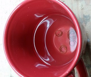
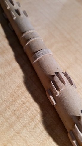
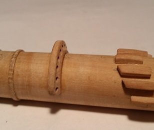
Although TFFM suggests making the Woolding Hoops with paper or card I decided to try making them from wood. I determined the greatest circumference of my mast at the hoop locations and found a piece of scrap about three times this length. I sanded one side to get about 3" (0.05" to scale) thickness, clamped it in my vise, adjusted the blade on my hand plane to get about 0.03" thickness and went to it. The pieces were placed (floating) in a cup of boiling hot water. Once they sank to the bottom they were removed, wrapped around the mast at the hoop locations, clamped and left to dry overnight. The woolding rope is 1" diameter and there are 13 to 15 turns. Each set are spaced adequately to accommodate these. The next day the clamps were removed and the curls of wood were carefully cut with a scalpel to provide a butt joint. They were removed, coated on the inside with yellow wood glue, put back in position on the mast with the butt joint on the bottom (6 o'clock) and re-clamped. The next day the clamps were removed and the hoops were slightly sanded. (There will be more sanding to be done)
-
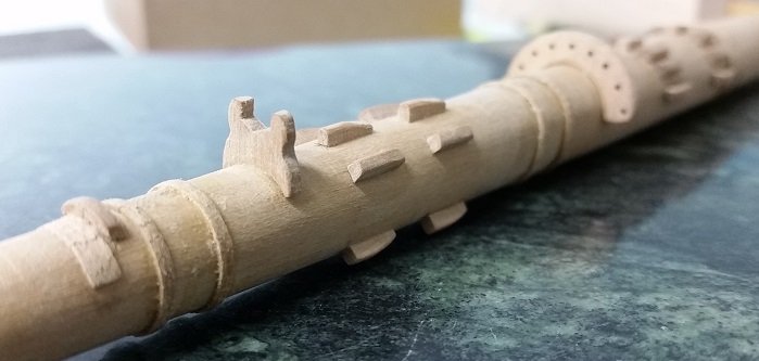
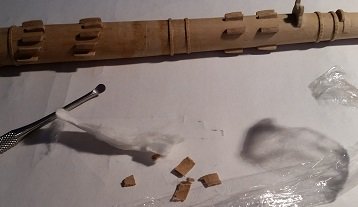
Then was the spritsail yard sling saddle. It is located under the jib boom, between the jib boom saddle and the Bees. This is comprised of a small stop block with a sheet of lead nailed to the top half of the mast as a wear plate. I simulated the lead sheet with a shaving of wood... using a hand plane. This will be painted to look like lead. While dry fitting the stop piece it fell to the floor twice. Each time it bounced out of sight and was lost... I had made it three times!
-
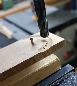
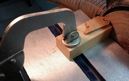
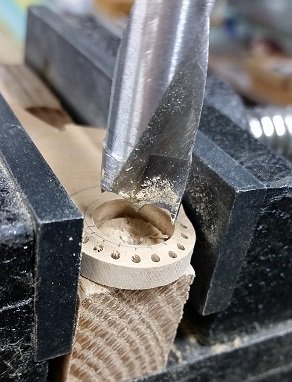
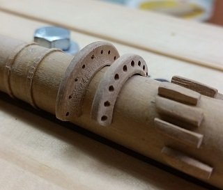
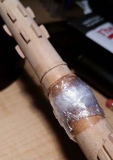
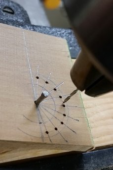
After finishing the cleats I made the nine hole fairlead. Full disclosure: I did this twice. It took a few days of chewing on it before I decided the first was just too tall to step over, and the rope holes were just too small. The process for both was the same. I scribed the Inside and Outside Diameter and then the Hole Circle with my compass, then laid out the radial lines for the holes. I found a finishing nail to use as a pin, and drill a centre hole to pin the piece to a base board. The piece could now be spun about on the centre pin. I first drilled the rope holes, then machined the aft face profile with a bull nosed cutter, and finally sanded the Outside radius into the piece before removing the pin. The last act was to drill a hole for the Inside Diameter and sand the flat face to the final thickness of 7-1/2" (0.12" to scale). The piece was cut off and the work was sanded to fit the mast. Above you can see the original one glued on and the new one placed beside it. I sanded the old one down to near the mast, soaked some cotton in rubbing alcohol, wrapped it around the remnant of the old saddle and wrapped that in plastic wrap. This was left overnight. This morning I removed the old bits quite easily, let things dry, sanded again, and glued the new fairlead in place.
-
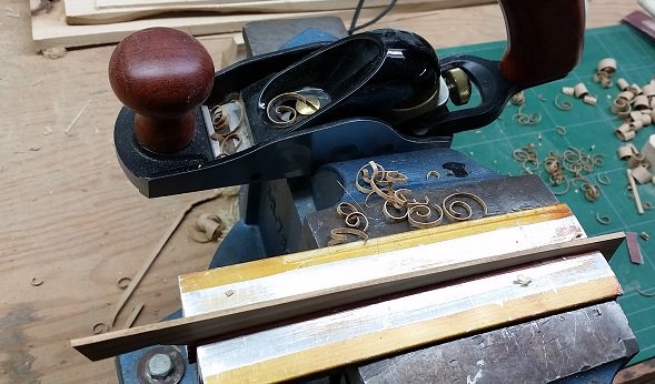
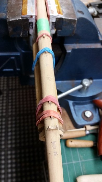
The cleat profile was sanded (yes that ugly word) into a long strip of wood. Each cleat was cut off the strip with a fine tooth saw The faces were cleaned up with more sanding Each cleat was (yellow wood) glued to the mast and clamped in place with elastic (rubber?) bands... and there is my second jib boom saddle but there was something about it that bothered me so a few days later I made a third and final one.
-
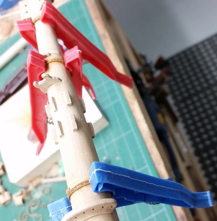
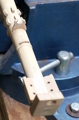
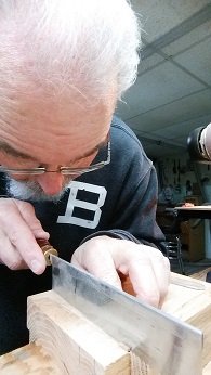
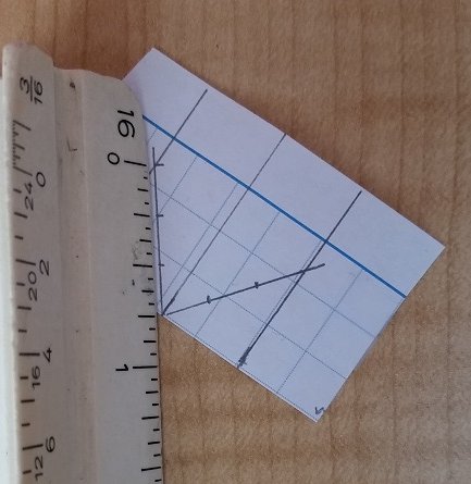
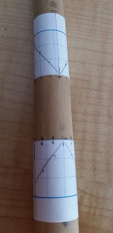
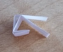
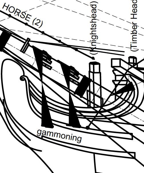
Marking off the cleat locations After having drawn it up, placed the bowsprit on the build and double checked the gammoning cleat locations to the gammoning holes (which I discovered were too short a slot for the minimum number of turns in the gammoning rope) I needed to mark the cleat locations along the circumference of the bowsprit. There are seven gammoning cleats in a set of two rows above and forward of the gammoning slots in the stem of the build, and five thumb cleats in a set of two rows abaft the jib boom saddle. they wrap around the bowsprit for 180° with the middle cleat of each row at 12:00 (straight up), and the last at 3:00 and 9:00. I needed to establish 12:00 (up) on the bowsprit, and marked at each cleat location along the top of the bowsprit with a pencil. To get the locations of all other cleats in a set correct I used strips of paper. The individual strips of paper were wrapped around the bowsprit and marked with a pencil to indicate where they overlapped themselves to get the circumference exact. The paper was cut at the mark, then folded in half to indicate 12:00 and then folded in quarters to indicate 3:00 and 9:00. Pencil marks were made at these locations. The gammoning strips, as there are seven in a set, needed to be further divided into three equal spaces between 3:00 and 12:00 and between 12:00 and 9:00. This was done with a scale, using 3/4" as it was greater than the spacing and is easily divide in three (1/4" - 1/2" - 3/4"). These marks were made and transposed to the cleat edge of the paper. The thumb cleats on this build are located abaft the jib boom saddle, not forward of it. They are also radially spaced differently, and to confuse things, sources do not agree. There are five in a set but in this build they are unequally spaced. One is at 12 o'clock, a set at 45° off that (1:30 and 10:30?), none at 3 or 9 o'clock, a set at 45° off of those points (4:30 and 7:30?), and none at 6 o'clock. The strip of paper was cut to the length of the circumference of the mast at the specific locations. It need to be divided into quarters, so one additional fold was made in each half, from halves to quarters, this created the equal spaces for the circumference at that cleat set location. I simply needed to remember which locations to skip... and should have marked it on the strips of paper! The strips of paper were wrapped and taped back onto the bowsprit and the sets of marks were transposed onto the mast. The last step was to mark the set back location for each of the gammoning cleats. As the bowsprit is set at 30° rising incline the cleats fall back on each side to accommodate the change in angle. First I drew lines from the forward set to the aft set and extended the line aft of that. I set the bowsprit at 30° and with a 90° flexible plastic square (made with any plastic sheet) I set one edge to the table, back to the mast, gently wrapped it around the mast and marked off the set back amount with a pencil. It was right about here that I knocked my jib boom saddle off... it was in two pieces so I had to make another .
-
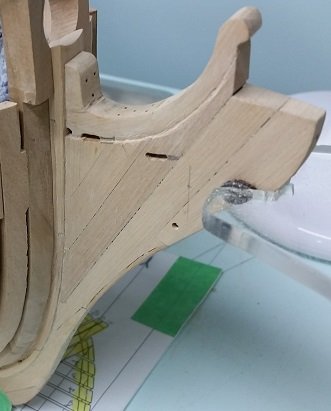
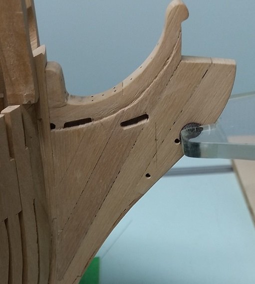
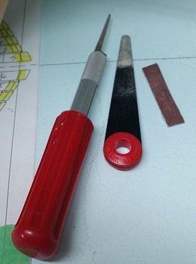
Having determined the locations of the gammoning rope cleats on a drawing I needed to confirm the locations by fitting the bowsprit I had previously made and lining things up with a weighted string. The forward face of my cleats must be aligned with the forward end of the slots. Also, my cleats and woolding hoop locations at 3 and 9 o'clock needed to be forward of the knights head. I discovered that the gammoning slots I had made per the Admiralty drawings were incorrect in length. Luckily the aft most locations of the slots were okay. They need to be elongated forward almost twice the amount of their present length. I marked off the spots with a pencil, double and then triple checked it. I fretted over how to accomplish this for a couple days, and finally decided to use my new long narrow nosed X-Acto saw blade to cut these slots longer, and then clean up with my flexible Japanese micro files u Of course I had quadruple checked the locations just before starting... the feat was easier than I had imagined.
-
So ... sanding is boring work. thank goodness I have many diversions. Having added all the features to my bowsprit I will add to my build log... starting with an update to the drawing and document I posted earlier. I found a few corrections were in order. Here is the complete package $ bowsprit rigging doc pkg- rev3.pdf
-
Craig Thank you very much for the confirmation and links. Fasinating reading as I've spent some time now transcribing post relating to the convict hulk Captivity, formerly the Bellerophon. Life on board the hulk was quite terrible but dear Sarah Island must have been hell on earth.
-
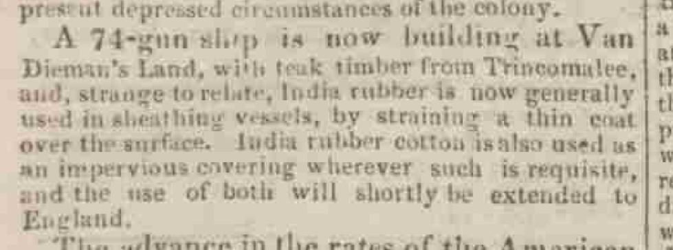
Sherborne Mercury- 14 Sept 1829
-
More improvements? - 1829 Are these being built by transported convicts?
-
I have issue 1 through 4 of Volume 31 Issue 1 pg 22 - table of small cordage from 3/4 to 8 inch and blocks dated 1711 (John Davis) Issue 1 pgs 31 - 41 Table of Blocks for American warships (Table No. 3 pgs 18-22) USN Table of Allowances dated 1826 Issue 2 pgs 72 - 97 Continued table of blocks (Table No. 3 pgs 23 -35) USN Table of Allowances dated 1826 Issue 3 pgs 146 - 159 Continued (Table No.4 pgs 38 -46) USN Table of Allowances dated 1826 Issue 4 - nothing Is anyone interested in any of these? Am I allowed to scan and copy the single page 1711 table here... or the multiple pages of USN tables? It is not the detailed book requested.
-
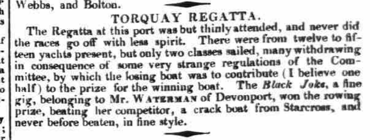
a strange sailing regatta rule indeed - 1831
-
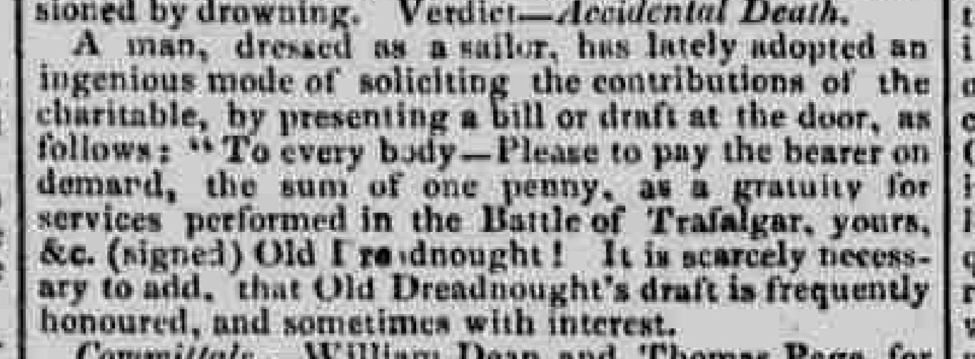
The perfect scam in 1831.
-
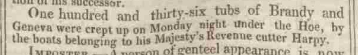
1829 - I'm trying to imagine this (Ssssssssssssssh! I'm hunting waskily wabbits)
-
okay, that's it for me. I will never drink another glass of water again. - 1828
.JPG.4a58e319b00765bfe5288a08f04e6f53.JPG)
-
Let's take a relaxing cruise... it'll be fun! - 1828
.JPG.487ad7a469e57fc9a1e2d2d26fda969b.JPG)
-
and once yet again... the more things change - 1828
.JPG.edf032b3b4b09e8ea386b58b967f8605.JPG)
-
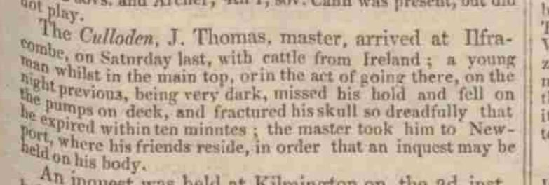
Terrible accident at sea - no safety harnesses back then - real men didn't need them (I guess that rules me out) - 1828
-
quite possibly the same fellow!
-
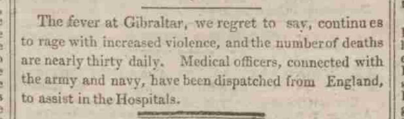
A medical emergency - a google search proved it to be Yellow Fever - 1828 Once again, the more things change... the more they stay the same
-
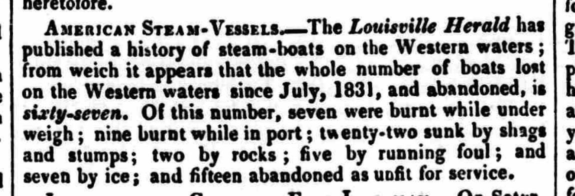
A talley of the loss of American steam ships - 1834
-
I suppose nothing much became of this as I cannot find the fellow in a web search - 1832