
HOLIDAY DONATION DRIVE - SUPPORT MSW - DO YOUR PART TO KEEP THIS GREAT FORUM GOING! (89 donations so far out of 49,000 members - C'mon guys!)
×


AON
-
Posts
2,866 -
Joined
-
Last visited
Content Type
Profiles
Forums
Gallery
Events
Everything posted by AON
-
This one I can, in a way, relate to. I've worked with particular entitled persons that had claimed, and attempted to claim, co-workers papers for publication.
-
thirty-eleven works for me. That makes me thirty-thirty-plus!
-
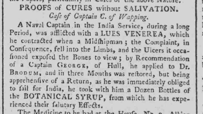
A bad case of "the sailor's itch" cured! - 1804 (I double dog dare you to pick "like")
-
Americans. (Canadians would have grabbed beer and chicken wings)
-
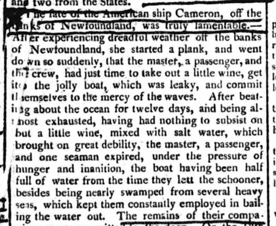
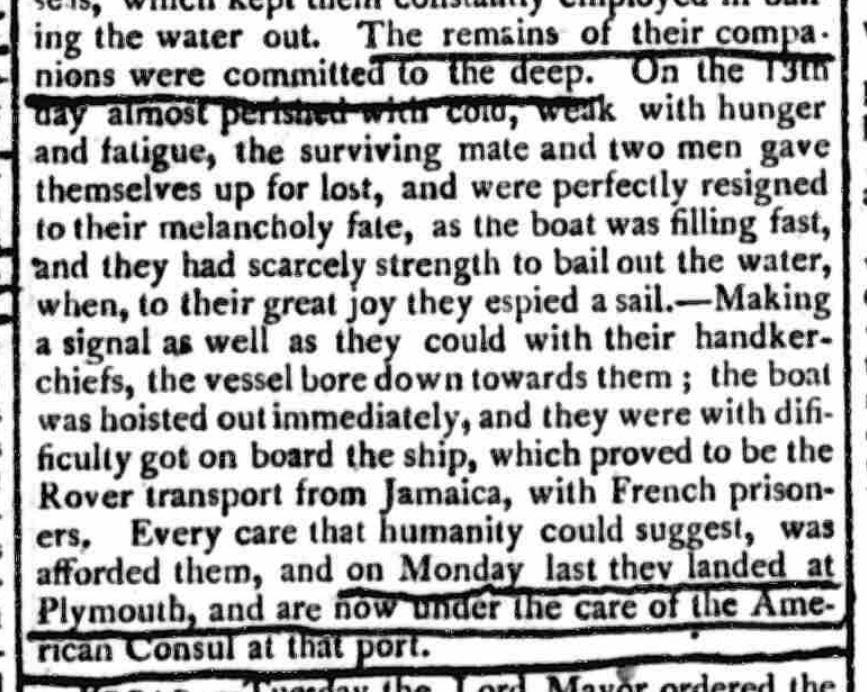
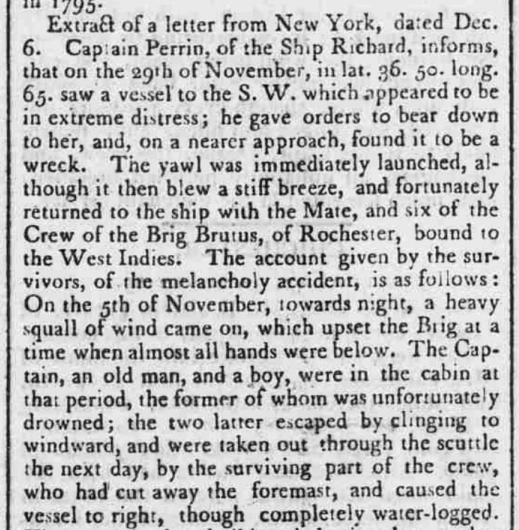
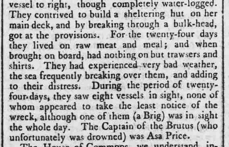
An extremely close call indeed.. for those few survivors... Dec 1804
-
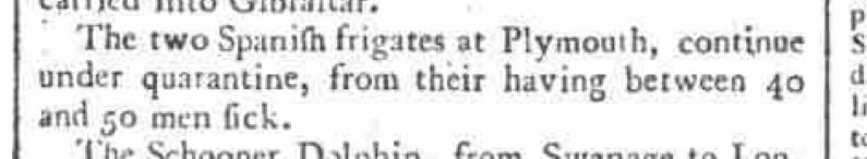
Okay now, no parties of two or more, practise social distancing, and wash those darned hands sailor! - 1804
-
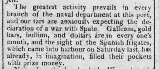
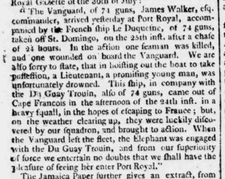
Could they actually have been anxious for yet another war? Oct 1804
-
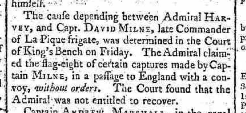
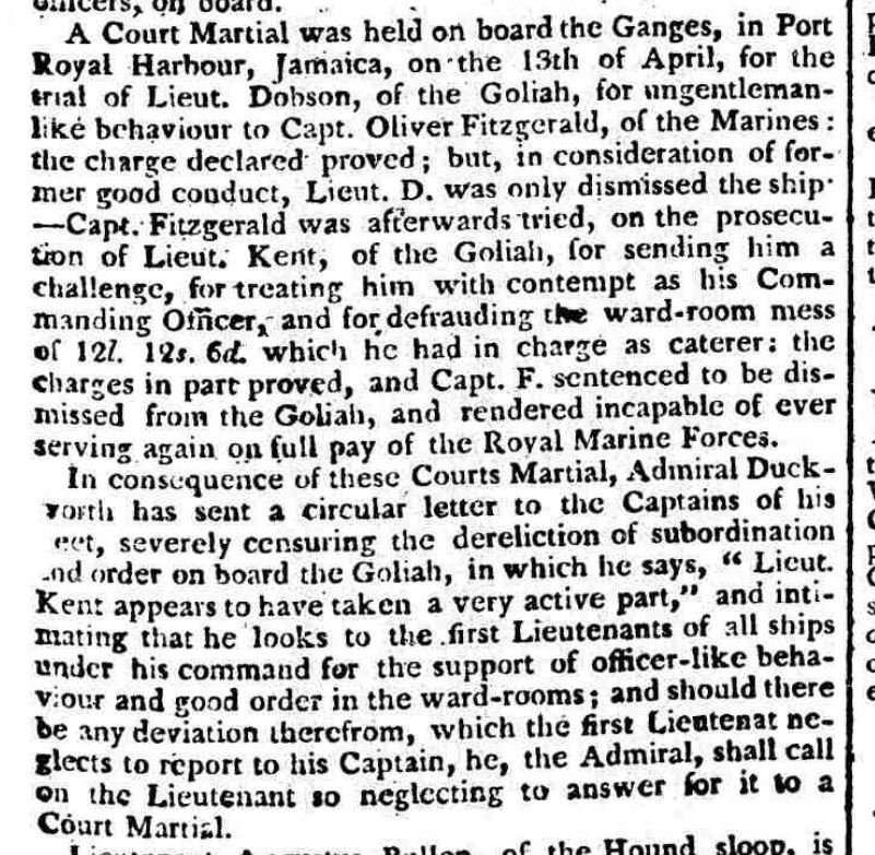
There is always someone that just has to ruin a good thing.... 1804

-
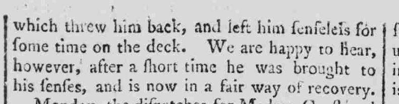
some people were just born lucky - 1804

-
Say what??- 1803
-
Arghhhhhhhh! He be a traitor for sure. Keel haul 'em and then hang 'em from the yard arm till he dries out. Then do it again!
-
Yes. Quite! At first I imagined it might have some Irish relationship and might had possibly been due to "the flight of the Wild Geese". But a quick google of the surname killed that idea.
-
A Sailor's Poem : The Burial - 1803

-
reporting in - 1803
-
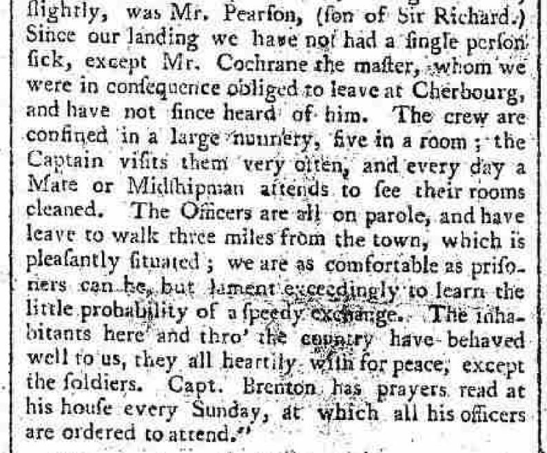
One way to treat prisoners of war... a nice relaxing vacation in the low mountain region of Epinal, France. T'was a more civil time.

-
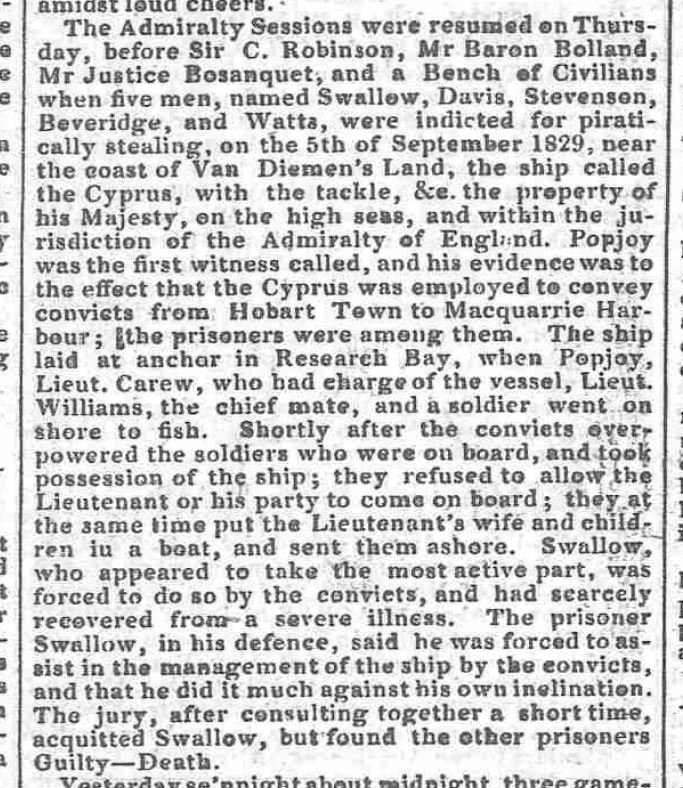
that ought to teach them not to take the keys and go for a spin in the harbour - 1830
-
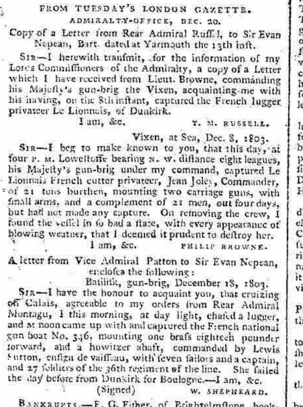
The cruel sea - 1803
-
Nothing is easily achieved - 1803
-

74-gun ship by Gaetan Bordeleau - 1:24
AON replied to Gaetan Bordeleau's topic in - Build logs for subjects built 1751 - 1800
You must have a local (city) museum that would jump at the chance to have it donated. This way your work will be on display for relatives years after we are all dust and lost memories. -
Extreme measures in an extreme case - 1830
-
Druxey Thank you for the quick reply, but now I am confused as the head/tenon on your photo is cut at an angle rather than square cut. I would have bet you were referring to the portion that fits through the cap, that it should have be square cut to leave a wedge shape protruding through as in the references I gave. The head of my bowsprit is finish with the cap, bees and bee blocks. The shape you refer to was done but is behind the blocks. Now I am not sure I should add a wedge to the head of my bowsprit or not.

-
Druxey, Do you mean the square wedge bit I see poking through the cap in TFFM photos on pgs 82 and 91. I see it also in Rees's, Plate VIII. And also in The Masting and Rigging of English Ships of War, pg 8. Until now I'd only noticed other references I had looked at showed it flush... so I cut the darned bit off ages ago! Historic Ship Models - Wolfram zu Mondfeld - pg 227 (bowsprit head after 1780) The Anatomy of Nelson's Ships - C Nepean Longridge - pg 185 fig 116 Yes, I should have paid better attention to the contemporary sources Now I have to stick the "gum dang" thing back on (a Dan Blocker, Bonanza reference). Oh Joy.
-
Thank you Jason and Jim. Being a novice I am very proud of what I've done, though it's taken ages to get this far. I've not done it on my own, meaning, I've had a good amount encouragement and excellent guidance. If only I found some enjoyment in fairing the cant frames they'd be done by now.
-
I owe an apology to those nine souls that downloaded my updated document with drawings in post 1050. The sketch with the locations/positions of the two sets of five thumb cleats aft the jib boom saddle had not been switched out to show the position pattern I used. It has now been switched out and identified as rev3. Sorry for that but my checkers are practising social distancing
-
Thank you again Craig. It was a long read but very descriptive! I just kept going... as did it. followed by kangaroos, birds, caterpillars and the local dialects
