HOLIDAY DONATION DRIVE - SUPPORT MSW - DO YOUR PART TO KEEP THIS GREAT FORUM GOING! (89 donations so far out of 49,000 members - C'mon guys!)
×


AON
-
Posts
2,868 -
Joined
-
Last visited
Content Type
Profiles
Forums
Gallery
Events
Everything posted by AON
-
and time moved on... progress in 1815 with steam boats

-
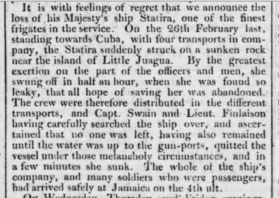
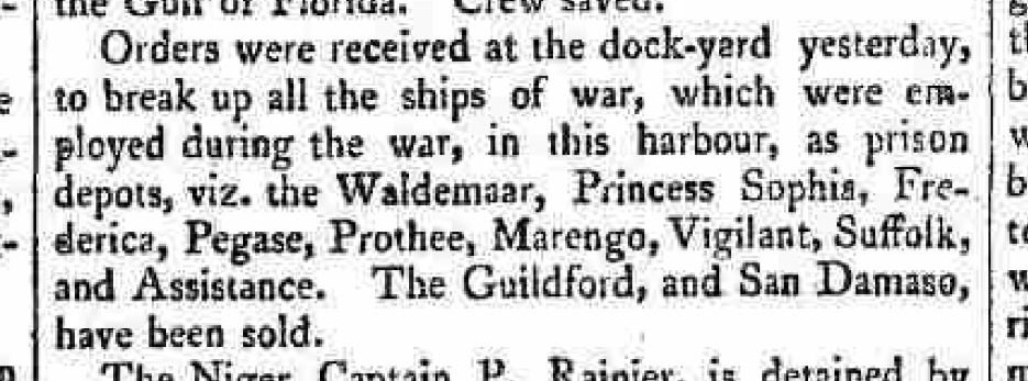
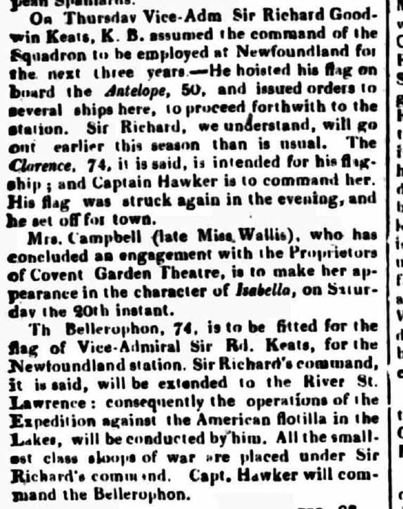
and... wars are over. So do what ever you want, the Admiralty needs a break - 1815

-
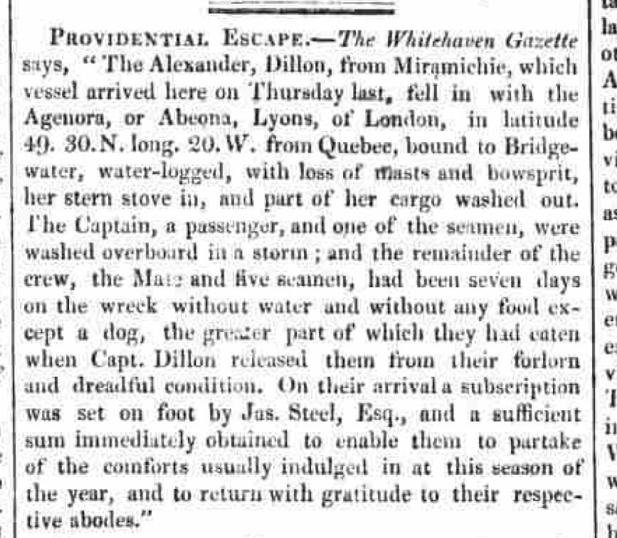
Thank goodness he didn't decide to go down with the ship - 1815
-
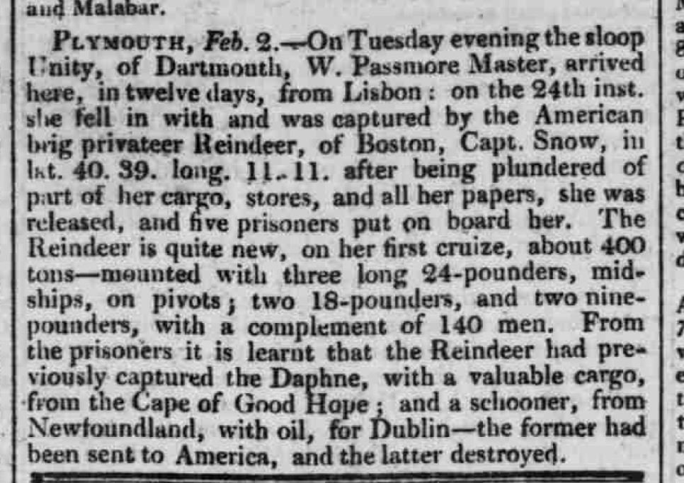
The war with the USA end a mere twelve days later on the 18th - post dated 6 Feb 1815
-
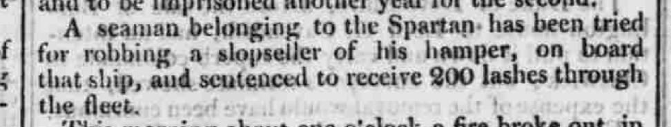
LASHES THROUGH THE FLEET: A form of punishment in the old days of the British Navy for the more serious crimes committed on board. It could be awarded only by sentence of a court martial. The man undergoing sentence was placed in a boat in which a ship's grating had been lashed upright across the thwarts, and rowed alongside each ship lying in harbour. While bound to the grating he was given twelve strokes with a cat-o'-nine-tails by a boatswain's mate of the ship off which the boat was lying. After each infliction of a dozen strokes a blanket was thrown across his back while he was being rowed to the next ship, and it was usually necessary to ‘comb the cat’. A naval doctor was always in attendance in the boat to make certain that the man undergoing punishment was fit to receive further instalments of his sentence as he came alongside each ship. In each ship visited the crew were mustered on deck and in the rigging to witness the punishment, drums on board beating out the ‘Rogue's March’ as the boat approached.
-
And this is one mans story of what happened... - 1815
.JPG.7ac875d6f5b789fce545cade01950955.JPG)
.JPG.ebd70870a1f0a2b0a2fe931408f54360.JPG)
.JPG.5557e2d8b53dbdfb27c91d64e67dc117.JPG)
-
Oh, what to do with all this surplus stuff? - 1814
-
I hear a new verse in my head to 'What do you so with a drunken sailor?' When I took my PL course the first thing they made us do a 6 AM was jump off the jetty, be it high or low tide, didn't matter. And I can attest to the fact that looking down was worse than looking up (for me). Then they made sure we could tread water for a minimum of 30 minutes. And they didn't care that the water was damn cold or that the boats officer had a photo of a 15 foot shark they'd caught off that jetty hanging on his wall. Then they taught us to make a flotation device from our trousers to buy us more time. Of course that only counts in a day and age where ships can turn on a dime in most weather conditions, otherwise I suppose, you are fish food. I've read enough 200 year old publications now to know swim or not, your chances back then were from not good to really. really bad..
-
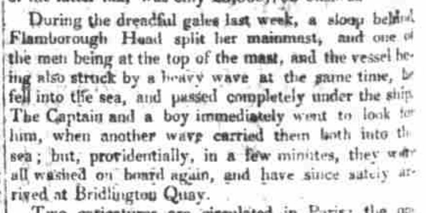
The number of sailors that could not swim was absolutely amazing. - 1814 Did he not hold on to the horse (safety lines)?

-
and... what an idiot.. 1813
-Mar1813.JPG.5c1d1afa9db278c081111f7fbfdb7641.JPG)
-
We will never see such a sight again - 1813
-Feb1813.JPG.c471e7a204ed1b57e0ccaa6d884f5e17.JPG)
-
We will never see such a sight again - 1813
-Sept1813.JPG.ef7355731c6f1a1432a27de9d74f5e35.JPG)
-
War of 1812 (1812 - 1815) between the USA and Great Britain fought in North America and the North Atlantic. Here is a report from Lake Erie - 1813

-
Could they possibly be attempting to confuse the enemy... in this case the Americans. There are three stories. Ignore the short middle one. The true story is ... well, both of them. It appears the Admiral couldn't make up his mind, plus, this story appeared in a British India paper, so by the time they printed it, it was old news.
-
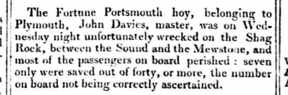
With all the tragedy in this report, I couldn't help but wonder if Shag Rock was anything like Blueberry Hill? - 1813
-
I heard tell of this happening - 1812
March1812.JPG.f4433e1132232711be12049b63125467.JPG)
-
Had they waited a few years (1939) they may have been able to use them again.
-
skilled tradesmen has a freakish accident - 1811 (a bit difficult to read)
-April1811.JPG.20c81e846fed0d0e6898145be2044645.JPG)
-
this one may be a bit difficult to read but if you can manage... what are the odds of this happening - 1816
-
 sorry for the late reply the wife decided to shampoo the rug and I lost access to the computer! seeing the shape in your post above, I would suggest Druxey's simplified method would be much easier, and for modelling, be more than adequate!
 -
call to exploration - the North West Passage - 1817 Franklin would attempt this years later and perish in the attempt.
-Nov1817.JPG.f5e191d44dffc57d33a74b946f66210d.JPG)
-Nov1817.JPG.d302ff9a75ecefdc051b4a2a2300ea3d.JPG)
-
Mark If the curve is one radius: 1. calculate the circumference of the circle (360°) at Circumference = π × diameter = 2 × π × radius. where π = 3.1416 2. determine the portion of the arc of the radius in degrees (a portion of the 360°) 3. the flat length is the ratio of the two (#2 above/360°) times the circumference of the circle (#1 above). To determine the location at lengths along the arc of the circle simply break it down to smaller ratios of portions of the arc. Then multiply these smaller ratios by the circumference and you have the flat length location for the smaller segment along the arc. If the curve is comprised of a number of conjoined but different size radii, break them down, and do the steps above for each. I hope I have explained this clearly. If not I am certain I have an old draughting book here with an example that I might scan and send you. Alan
-
with all the "nautical" postings here I hope no one will mind one of a different kind that I could not resists... 1819
-
Cheech and Chong... I can hear them now: "Hey man, what'chew do'n hang'n 'round here?"
-
they were a tough lot