Search the Community
Showing results for tags 'ironclad'.
Found 10 results
-
 Donald Canney specialized in the transition period of sail to steam power and wood to steel construction of the US Navy. He worked with the US Coast Guard as registrar for that service’s national artifact program from 1991 until his retirement in 2006. While the world’s navies of 1861 to 1865 were making this transition of sail to steam and wood to iron, the American Civil War provided the impetus to speed up that evolution on both sides of the conflict. The Confederate Steam Navy details the ships of the Confederate Navy from 1861 to 1965. The author focuses on ships with steam power and those converted to steam power. The text provides a lot of insight into all aspects of the transition covering technology, politics and logistics of building each boat. He also outlines the careers of each ship during the conflict. The first six chapters cover the ironclads from the early beginnings of the conflict. He devotes a chapter to each year of the war when discussing ironclad battleships. The author covers every ironclad ship involved in the Confederate Navy. I use the term ‘involved’ loosely as Canney includes ships that were under construction but never completed. Most of these were destroyed due to the eminent capture of the shipyards by Union forces. Some ships he discusses were under construction in Europe (particularly England) and were confiscated due to the political stances of England with regards to the war in America. He outlines the final disposition of these ships, too. For the ships discussed he explains the hull construction, the engines; and other aspects of ship propulsion; and the ships' armament. His descriptions tell about the material used for the hulls including dimensions along with the types of wood and iron employed. He provides details on the steam engines based on their classification of pressure, size of cylinders and stroke length. He details how the engines were installed and the propellers for the ships. He describes the deck arrangement and sizes of the various guns used on each ship. While covering these details, Canney points out issues of internal conflicts between the Confederate Army and Navy. He points out the Confederacy's lack of industrial base for supplying the necessary materials (plate iron specifically) to all who needed or wanted the material. (As a side bar, Canney includes a 2-page appendix titled “Notes on 19th century shipbuilding and steam engine technology.” I suggest readers start with this appendix as the author explains the terminology particular to how measurements were made during that time in history and terminology pertaining to steam engine technology. These notes explain the shift in terminology from one ship to another in his descriptions of these aspects.) After covering the ironclads, Canney devotes chapters to many other steam powered ships and boats including blockade runners, commerce raiders, gunboats, and floating batteries. Some of these chapters select a few which were representative of the literally hundreds of such boats brought into the Confederate Navy. Canney bases his observations and conclusions using source documents from those who served on board, were spies who collected information for the Union, after-action reports and descriptions of the ships after they captured. He points out discrepancies he found between the various information sources. While the book has many black and white drawings, photographs and paintings of ships and their components, for the modeler they may not be extremely useful. The illustrations are small and lose detail due to the reduction on the image to fit in the book. However, the author includes the source of the illustration so that a serious researcher has a starting point for further investigation. While the book is not for casual reading per se, I enjoyed reading the details on ship names I recognized from board games (Ironclads - Yaquinto Games; Shot and Shell”- 3W Games). Along with my gaming experience, the bibliography and and notes leads me to believe that Donald Canney provides a comprehensive listing of the steam powered vessels involved in the Confederate Navy. He provides good representatives for the non-battle ships of the times. The book provides details not normally found in other book on thehistory of the battles involving these historic ships. I'd recommend this book for serious students of ironclad and steam powered vessels from this period of nautical history. BOOK DETAILS Title: The Confederate Steam Navy 1861 -1865 Author: Donald L Canney Schiffer Publishing, Ltd. 2015 Hardback (9-1/8 wide X 8-3.8 tall); 192 pages (includes end notes, bibliography, and index) Twelve chapters each dedicated to different classes of steam powered ships of the Confederate Navy Black and white images: photos, drawings and paintings Cover price: $39.99 Available on Amazon and Barnes and Noble websites ISBN: 978-0-7643-4824-2
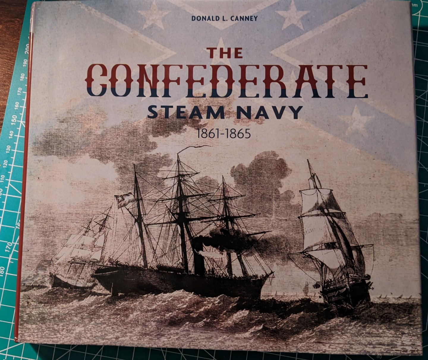
- 2 replies
-
- 4
-

-
- ironclad
- Confederate Navy
- (and 7 more)
-
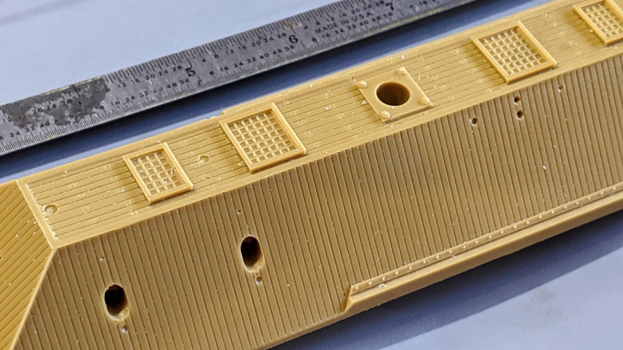
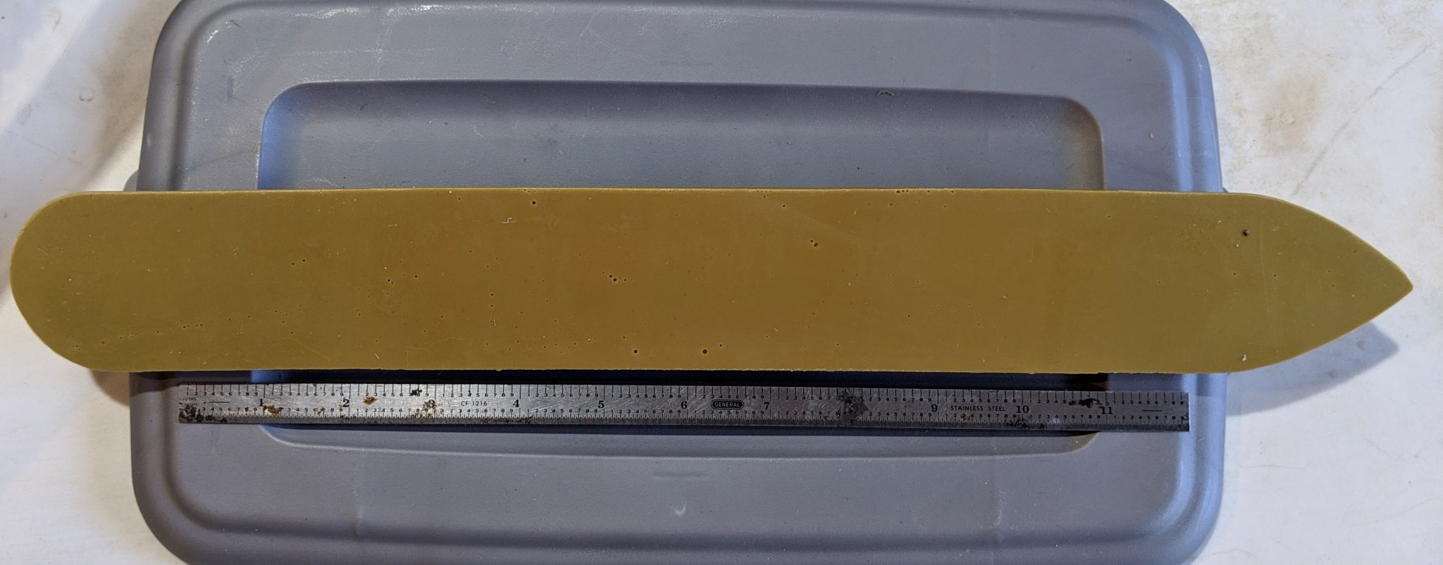
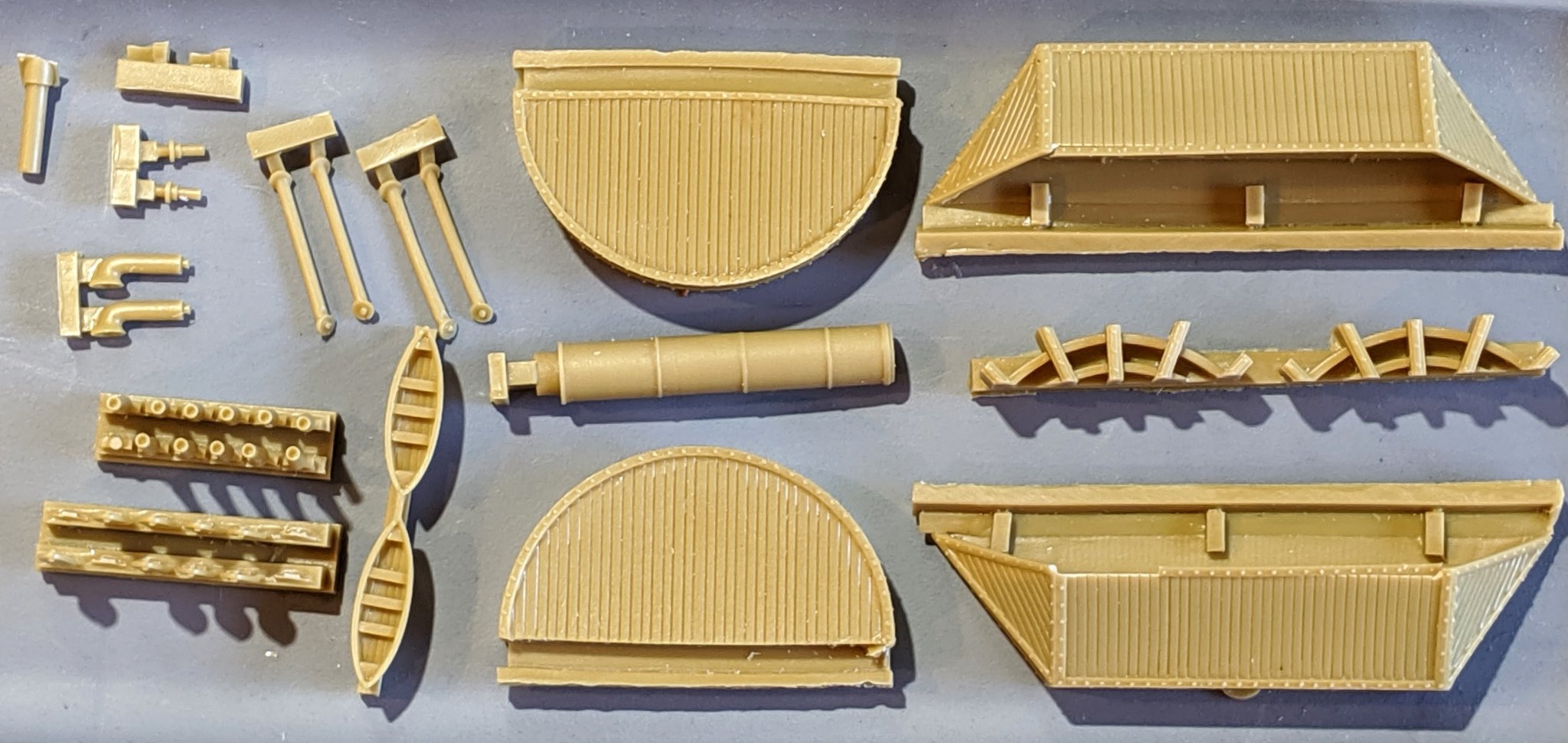
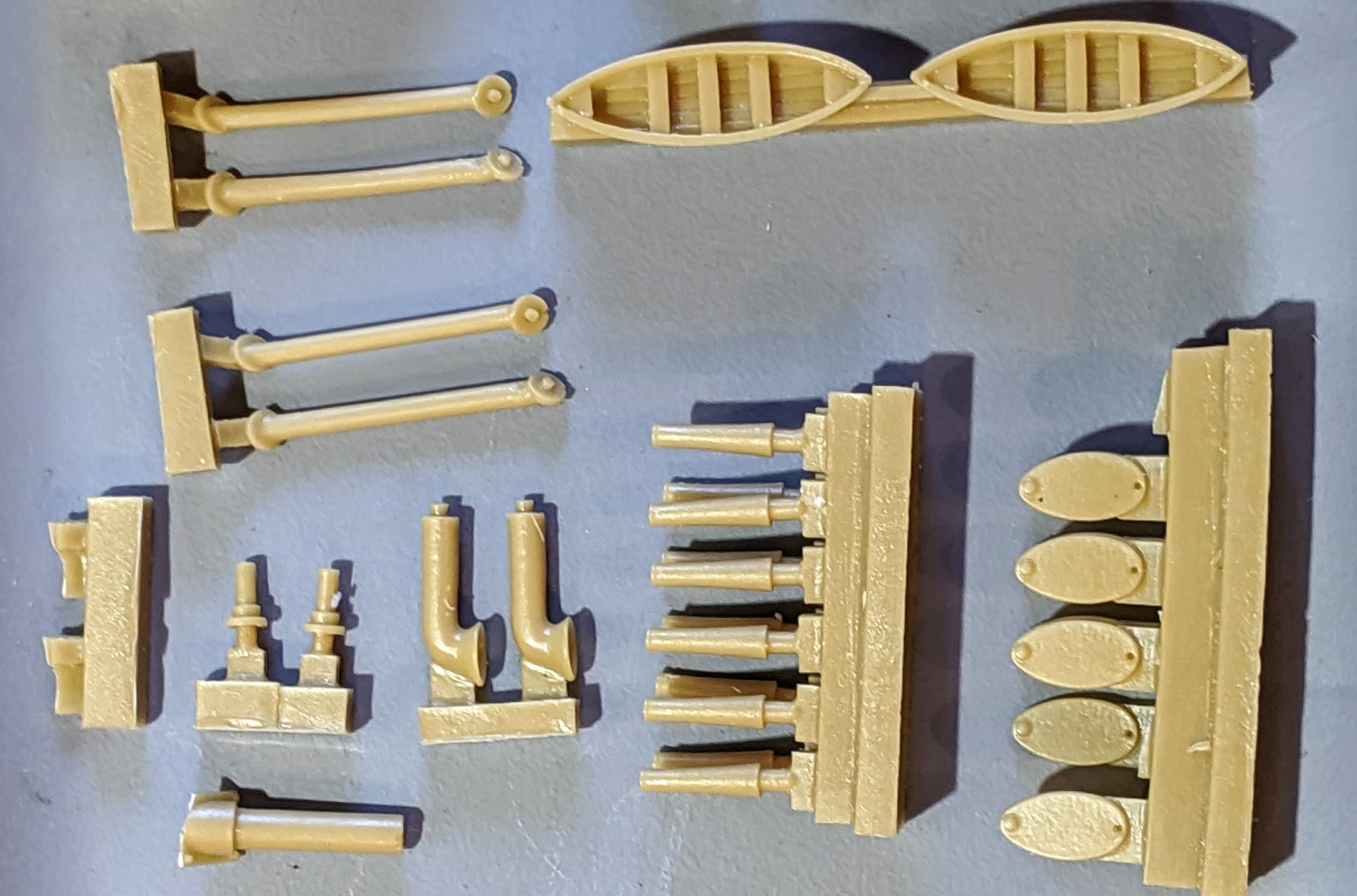
 USS KEOKUK: The Ship that Could Have Sunk the Merrimac. Historical and Technical Overview A Brief Revisionist History Notional view of the engagement between USS Keokuk and CSS Virginia (aka Merrimac.) Painted by Patrick O'Brien. Frank Leslie’s Illustrated Newspaper – March 29, 1862 (fictional account) Hampton Roads, Virginia, March 9, 1862 – from the deck of the U.S.S. Minnesota. In her first battle, our Navy’s new iron-hulled, steam-powered ram U.S.S. Keokuk, under Captain A.C. Rhind, has today engaged and sunk the iron-clad rebel ram Merrimac, which but the day before had destroyed our gallant warships Cumberland and Congress, with considerable loss of life, and inflicted slight damage upon the Minnesota, grounded during the battle. When Merrimac returned this morning with her consorts to resume her attack of the still-grounded Minnesota, she instead was met by the much smaller Keokuk, secreted from easy view behind the Minnesota during the night. Keokuk arrived in Hampton Roads but the evening beforehand, and was made ready to avenge the Cumberland and Congress at the first opportunity. As the unsuspecting Merrimac came within easy range of Minnesota, Keokuk emerged from behind her bows and had straight at Merrimac at a speed that startled both your writer and several members of Minnesota’s crew, standing nearby at their gun stations. Without doubt the rebels were equally startled, as almost immediately, Merrimac’s two lightly armed consorts steamed away back toward Sewell’s Point with all possible haste, leaving Merrimac alone to deal with this peculiar-looking, but clearly fast and nimble, new adversary. As she bore down on Merrimac, Keokuk turned out wide to her right in what appeared a maneuver to better position herself for a broadside ramming. Merrimac responded by trying to turn her bows to Keokuk and to move away from the shallow water on her right, but she was slow to answer her rudder. A few scant seconds later, Keokuk drove her five foot long solid iron ram into the left side of Merrimac. Coming together at such great speed as they were, there was a thunderous crash, much like a thunder-clap, that could be clearly heard by your writer one-half of a mile distant. Merrimac was mortally pierced on her left side, eight feet beneath her waterline and in a location that the Captains of both ships could doubtless clearly see each other’s faces from their pilot houses. Thus coupled, Keokuk remained at full ahead power to drive her ram deeper into Merrimac’s wooden hull, propelling the much larger ship sideways with seeming ease in an attempt to ground her. What few rebel guns that could be brought to bear in response fired only glancing blows, due to Keokuk’s all over rounded shape and iron skin. Some damage was done to the armor on the right side of the hull and turrets. The water churned frothy brown around the two ships, with Merrimac, like a fish on a spear, struggling to get away, and all the while Keokuk trying to drive Merrimac further into the shallows. Those gun crews on the left side of Minnesota with a clear shot, poured cannon fire into the right side of Merrimac. No rebel fire was directed at the Minnesota or Dragon during the battle. Keokuk then proceeded to engage Merrimac’s iron armor where it met the wooden lower hull, with her forward XI in. Dahlgren shell gun, firing solid iron shot of 165 pounds weight, from a distance of less than 40 feet. It took but two shots, into the area weakened by the ramming, to completely expose Merrimac’s gun deck through a hole so large that a sailor standing near to your writer exclaimed he, “could easily pass down the foredeck of Keokuk and into Merrimac walking straight up with my arms spread wide.” Likely fearing a third shot by an explosive shell would pierce her boilers or ignite her powder magazines, and being unable to maneuver off Keokuk’s ram, the rebel commander struck Merrimac’s colors just before eight o’clock this morning. Our gun-boat Dragon came alongside Merrimac and brought her surrendered officers and crew into captivity, transporting them to the Minnesota, much to the jubilation of the awaiting crew, who had suffered greatly at Merrimac’s hands the day before. In an act of humanity, the rebels were allowed to carry away the mortal remains of six shipmates, killed during the exchange of gunfire. Mercifully, the entire crew of Keokuk was spared all but some minor injuries. When Keokuk withdrew her ram, the now unattended Merrimac lost the buoyancy provided by the same, and exposed her inner hull to an onrush of sea water. She immediately began to settle by her forward left side, as Keokuk backed well down, anticipating an explosion. Instead, when the sea water reached Merrimac’s boilers, an immense white plume of steam billowed hundreds of feet into the morning sky. Resounding cheers of “HURRAH!” went up from the Minnesota and Dragon at this sight. It is believed that an explosion was avoided by failure of the rebels to attend to Merrimac’s fire boxes for the hour preceding. By nine and a half o’clock, all that remained above the surface of the now-calm Hampton Roads were the tops of her tattered smoke pipe, and the flagstaffs where the rebel colors had so proudly waved but one hour and a half beforehand. It is to be determined if Merrimac can be raised, repaired, and properly returned to Federal service, as to this day she remains a commissioned warship in the United States Navy, albeit briefly set to misdeeds by the rebels under the name “C.S.S. Virginia.” As of now there are three major warships resting on the bottom of Hampton Roads, all within easy sight of each other. Victorious Keokuk has been ordered to make all necessary repairs and proceed immediately to Charleston, South Carolina, to join in the blockade of that vital rebel port. It is known that at least one and possibly more rebel iron-clad batterys similar to Merrimac are being made ready there to attack our blockading ships. Keokuk will doubtless despatch these vessels with the same alacrity as Merrimac, should they be foolish enough to venture beyond the protection of the inner harbor shore batterys. As she appears to be one of the fastest warships in the U.S. Navy, she will likely be set to the additional task of seizing or sinking any blockade runners attempting to enter or leave the inner harbor. Navy Secretary Welles has ordered that all Federal Blockading Squadrons be equipped with at least one iron-hulled ram of Keokuk’s manner, at most possible haste, for further protection of wooden-hulled Federal ships from rebel iron-clad rams. Construction will be temporarily suspended on iron turreted batterys, including Monitor and Catskill, until all squadrons are suitably equipped with rams. As reported previously by your writer, plans are already underway to construct an iron-hulled ram of nearly four times the size of Keokuk. Back to Reality That is how the history books could have recorded USS Keokuk’s first engagement, had she been built a year earlier and sent to Hampton Roads instead of USS Monitor. But rather than receiving the praise heaped on Monitor for fighting to a draw with “Merrimac” – a contest that Keokuk would have won handily – barely 13 months later and just four months after sliding down the ways, Keokuk was at the bottom of Charleston’s Main Ship Channel after her first engagement, labeled a pariah. The fact is that Keokuk was a technological marvel for her time, equal – and even superior – to Monitor in many respects, and a purpose-built ship never used for her intended purpose. Even worse, she was immediately put into a situation that her designers explicitly warned against: placing her within range of heavy ordnance. On the technological downside, had Keokuk been built and sent to Hampton Roads instead of Monitor, “ram fever” would likely have replaced “monitor fever” in the Union Navy. Rams were nearly at an evolutionary dead-end in 1862 and became totally obsolete as soon as double wall iron hulls and large caliber, rapid firing, rifled guns appeared on nearly all capital ships. As such, by selecting the Keokuk ram design over turreted batteries like the Monitor - almost guaranteeing near term successes against the Confederate wooden-hulled iron clad rams - warship technology development would have been dealt a blow that could have set it back by several years. Launched on December 6, 1862 by J.S. Underhill Shipbuilders at 11th Street in New York City, Keokuk was from her conception incorrectly labeled and marketed to the Navy Department as a “battery”: which was essentially a floating fort. She was too lacking in armor and guns to serve as a battery. Keokuk was in fact a ram: probably the finest in the world at that time. Her singular task was to drive her five foot long integral iron ram into the side of a wooden-hulled ship and engage the weakened area pointblank with an 11 inch Dahlgren shell gun, one of the most powerful ship-borne guns available. Merrimac had already proven the effectiveness of an ironclad ram against wooden hulled warships by destroying the Cumberland and Congress and grounding the Minnesota, all in one engagement. But for all her initial successes, in comparison to Keokuk, Merrimac was grossly under- powered and under-armed. USS Keokuk being readied for launch at J.S. Underhill Shipbuilders. This is a surprisingly accurate depiction, down to the correct number of armor bands and the iron strakes into the conformal ram. Keokuk with her two independent 7 foot 6 inch diameter, 13 foot pitch, four-bladed screws; two, twin-cylinder 250 horsepower propulsion engines; and 9 foot draft, would have easily outmaneuvered Merrimac and rammed her, something that the single-cylinder engine / single-screw Monitor was unable to accomplish. Also, with half the speed and over twice the draft of Keokuk, Merrimac would have been unable to outrun Keokuk back up the Elizabeth River to the protection of Confederate shore batteries had she chosen not to fight. Following astern, Keokuk would have quickly disabled Merrimac’s stern gun, overtaken her, and destroyed Merrimac’s lightly protected rudder and propeller with her iron ram. Like Merrimac, her ram was Keokuk’s primary weapon. She was designed for frontal attacks with lightly armored flanks, where Merrimac was designed more like a battery to be used in broadside exchanges. Most importantly and unlike Merrimac, Keokuk’s ram was an integral part of the ship; with reinforced iron hull plates and reinforcing strakes extending into a ram shaped bow, with an iron core that was an extension of the stem post. In contrast, Merrimac’s ram was added on to the wooden hull and broke off inside the Cumberland the first time it was used. Keokuk would have been impervious to return fire while running in to ram, as what little frontal hull area that was exposed was a 20-foot long, innovative flooding compartment, separated from the rest of the ship by a watertight bulkhead, and designed to raise and lower her profile with steam-driven pumps that could maintain her at the desired trim regardless of how many additional holes were shot into the forward compartment. An elevated, sloping pilot house with only four small viewing slits facing forward ensured reasonable protection for the captain, pilot, and helmsman, unlike the muzzle-level, vertical-sided box arrangement on the Monitor. The only possible Achilles Heel when ramming would have been the shutters on the forward gun port, but the gun was just a secondary weapon to help speed up destroying the adversary. Keokuk’s first and only engagement came on the afternoon of April 7, 1863, when she joined Admiral Du Pont’s poorly conceived and executed attack on the heavily fortified port of Charleston, South Carolina, which had Fort Sumter, or “Sumpter” as its linch pin. The fleet was composed entirely of ironclads and in part was meant to show the superiority of these new, high-technology Federal weapons. But of the nine ships involved, only the flagship New Ironsides was specifically designed as a floating battery: a ship that could anchor and slug it out with shore batteries on an equal footing. The rest were designed to fight other ships. Equipped with fourteen 11 inch Dahlgren guns, and two Parrott rifles, had New Ironsides been able to run the gauntlet, accompanied by Keokuk or one or two monitors for protection from the ironclad rams Palmetto State and Chicora, and enter the inner harbor, she could have laid waste to the city of Charleston and possibly forced its surrender in the summer of 1863. As is, during a three month period in the fall of 1863, New Ironsides fired over 4,500 rounds of 11 inch shot and shell into the forts around Charleston: over half a million pounds of iron. The Union fleet line of battle, April 7, 1863, with Keokuk bringing up the rear and depicted much larger than she actually was: ¾ the length of USS Nahant immediately in front of her. Without land forces in support, the “attack” visually and tactically resembled a row of ducks in a shooting gallery. Instead, when the lead ship Weehawken with its fouled propeller and torpedo net stalled at the buoys of the floating barricade strung between Forts Sumter and Moultrie, the parade of ships broke formation and became a tangled mass fighting the tidal surge through the narrow mouth of Charleston Harbor. Caught in the crossfire between the surrounding forts with little room to maneuver around each other, and all the while fighting the tidal surge, it is estimated that within 30 minutes, over 3,500 Confederate artillery rounds were rained down on the fleet from a semi-circular ring of five forts. With forward progress to the inner harbor stalled by floating barricades and torpedoes, the Union fleet engaged in a disorganized shooting match with the forts: outnumbered in guns by a ratio of over 10:1. When Nahant, immediately in front of Keokuk, received a direct hit to the pilothouse roof that killed the pilot and wounded the helmsman, Keokuk was forced to maneuver around her while still staying within the narrow channel. New Ironsides had great difficulty maintaining headway due to the tide conditions and her extreme beam and marginal steering, and signaled the other ships to disregard her maneuvering. As the only ship that day with twin screws, Keokuk certainly coped better with the tidal surge, continuing around the single screw monitors and eventually finding herself in the number two position behind Weehawken. At that point she could proceed no further up the channel and found herself within 600 yards of both Fort Sumter and Fort Moultrie, who barraged her with solid shot, hot shot, and rifled bolts for over half an hour. Keokuk's light armor was not designed to absorb such punishment, and her flanks and turrets were “completely riddled,” in the words of her captain, Commander Alexander C. Rhind, by the crossfire from the two forts. After receiving over 90 hits in less than 30 minutes, at least 19 of which penetrated the armor, many of them below the waterline and breaching the iron, single-walled hull, Keokuk was forced to withdraw out of range to the Main Ship Channel off Morris Island. The night was passed trying to save her, and it is likely that her biggest problem would have been dry coal for the boilers to keep the steam-driven pumps operating. Since she was a single-wall hull design, with the coal bunkers forming the outer compartments on the flanks of the ship, the bunkers were no doubt partially or completely flooded. As the coal chutes were low to the engine room deck, sea water would have been constantly pouring from the bunkers into the engine room. In the morning when the offshore winds picked up, the higher waves swamped her. She sank in about 20 feet of water 2,000 yards off the Morris Island lighthouse’s original location (the lighthouse had been torn down when the war began to deny the Federals its use for navigation.) Outside the effective range of Confederate shore batteries, the sinking was orderly, attended by a Union tug, and witnessed by many Southern soldiers and civilians on shore. There were reports of objects from the ship washing ashore “covered in blood,” which was most likely oil or grease, but certainly not blood. Largely due to the shallow water and her relatively flat bottom, Keokuk wound up on a fairly even keel with the tops of the turrets exposed at low tide. The wreck quickly filled with sand and the Union engineers declared Keokuk unrecoverable. As such, the blockading squadron did not put any emphasis on guarding the wreck site. This would prove unfortunate for the Union, as the two Dahlgren gun barrels were recovered by the Confederates and put to use in defense of Charleston. The Union experts had declared such a salvage operation to be impossible, at least until they read about it in the Charleston Mercury. A terse letter from Secretary Welles to Admiral DuPont clearly expressed his displeasure that DuPont’s squadron allowed this to happen. Of Keokuk’s 13 officers and 86 crewmen, 14 were wounded in the battle, most slightly, including Commander Rhind with a contusion to his leg from a piece of his ship breaking loose during the artillery barrage. One of the gun captains, Acting Ensign Mackintosh, later died from his wounds. He was one of only two fatalities sustained by the Union fleet, the other being Nahant’s pilot. Confederate forces sustained no casualties, due largely in part to Du Pont’s orders to the ships to direct all of their fire low, at the center embrasures of the forts. Keokuk’s Quartermaster Robert Anderson was awarded the Medal of Honor for shielding Commander Rhind from fragments when a shell hit the wheelhouse. April 8, 1863. Keokuk settles by the bows in the Main Ship Channel off Morris Island. Epilogue Had Union Navy decision makers been more realistic concerning Keokuk’s strengths and weaknesses, broadside exchanges would have been avoided and attacking forts would have been totally off the table. With 37 degree sloping sides, broadside hits from other ships would be at least partially deflected, but great care was still needed to protect her relatively thin composite wood and iron flanks from any shot at all. What Keokuk was specifically not designed for was exposure of her flanks to the plunging fire of heavy ordnance from shore batteries, which is exactly the position that she found herself in on April 7, 1863, caught in the crossfire of Forts Sumter and Moultrie. Most of the plunging shot would have hit the sloping armor of the turrets and hull casemates at or near perpendicular: one of the worst possible scenarios. Having been present during her construction, Commander Rhind well understood his ship’s vulnerabilities and tried to attack Sumter bows-on, using only the forward Dahlgren (the ram wouldn’t have done much damage to the fort!) Keokuk got off a total of three shots at Fort Sumter from the forward gun, which turned out to be the only shots she ever fired in active service. Her two cannon barrels, however, soldiered on after being recovered by the Confederates in a daring, near impossible operation, and were used in the defense of Charleston until its surrender. One is still on display in Charleston’s Battery Park. Keokuk’s untimely demise was no doubt helped along by the detailed descriptions of the ship published in the Scientific American, Frank Leslie’s Illustrated Newspaper, and the New York Times in 1862 during her construction. So detailed in fact that in today’s world they would have been classified as at least SECRET and withheld from the public. By the time Keokuk arrived in Charleston, Confederate artillerymen already knew how thick her casemate armor was, the angle of its slope, and that it ended three feet nine inches below the waterline. All thanks to diligent Northern reporters, Confederate spies, and lackadaisical intelligence security by the Navy Department. In partial defense of Admiral DuPont, Secretaries Welles and Fox knew they were sending his fleet of ironclads on a suicide mission, ordering him to “reduce” the forts, with no illusions about destroying or capturing them. In addition, Du Pont was implicitly instructed to commit all of his ironclads to the attack. He was ordered that after the attack, he was to hold two ironclads in reserve (he chose his flagship New Ironsides and Weehawken) and that all other ironclads “fit to move” were to be sent immediately to New Orleans. These instructions were sent prior to the attack, so there was a clear understanding in Washington that things might end badly, which they did. Had Keokuk been held back from the doomed attack and kept in Charleston instead of Weehawken, she would have been available to deal with the rebel rams Palmetto State and Chicora, which had driven the Union blockading squadron into deeper water with their attacks on the Mercedita and Keystone State a few months earlier. It is interesting to speculate on the outcome of Keokuk engaging both Confederate ironclads at the same time, but she had the same advantages over them that she would have had with Merrimac: approximately twice the speed, half the draft, superior weaponry, and above all twin propulsion engines and screws, which was of critical importance for tactical maneuvering in the tidal surges of Charleston harbor. At least one of the Confederate ironclads most likely would have been rammed and sunk and Keokuk would have still been able to withdraw, with possible heavy damage from broadside fire. The Armor Controversy Keokuk is best remembered and, unjustly, vilified by many naval historians for her inadequate, “experimental” armor cladding (wasn’t all armor experimental at that time?) of alternating one inch wide and four inch deep strips of iron and yellow pine, covered by a 1.25 inch thick outer skin of overlapping, bolted iron plates. The figure, shown full size, shows what the casemate and cupola armor cross section would look like if you were to rotate the figure 37 degrees for the casemate or 20 degrees for the cupolas and look down the side of either. The Corbett drawing helps make this a little clearer. Now, was this armor design really inadequate for its intended purpose? Probably not. It should be remembered that Keokuk was designed as a ram, which would have limited her exposure to mostly frontal attacks and glancing blows to the hull side, or casemate, armor running down the length of the ship, not broadside. She would have also been exposed to much smaller caliber ship guns than what she experienced during the attack on Forts Sumter and Moultrie. She was not a large ship and was fitted with “as much armor as she could float,” according to her designer. In the end she still came in at 172 tons over the design weight of 688 tons, which added nine inches to her draft and almost totally rendered useless her innovative fore and aft flooding compartment feature. A vindication of her armor and design is that although she sustained over 90 hits in 30 minutes, many of them penetrating her armor cladding and breaching her single wall iron hull, only 14 of her crew of 99 were wounded, most of them only slightly but with one later dying from his wounds. She was also able to withdraw under her own power and be kept afloat overnight before finally being swamped and sunk by high waves in the morning. Whitney’s proposed design for Keokuk’s casemate and cupola armor, reproduced full size. None of my research indicates that something else was used, and this arrangement is shown on the Corbett drawing. The outer skin attachments could be interpreted as flush rivets, but all written descriptions found indicate that flush bolts and six-sided nuts were used throughout, as shown on the through-bolt. This could have been a modification to the proposed design. Based on the description published in Scientific American, Dec 20, 1862, the main deck was lightly armored with ½ inch iron plate laid directly on the iron hull frames, then 5 inch thick caulked wood planks followed by a 1 inch outer iron skin made up of two layers of ½ inch thick overlapping iron plates. Written and graphic interpretations abound on the “novel” armor concept used for the turrets and hull sides or “casemates” consisting of alternating 4 inch deep by 1 inch thick iron and 1-1/4 inch thick yellow pine wood strips, followed by a 1-1/4 inch thick outer skin composed of three layers of overlapping iron plates. According to the engineering drawing of 1863 by Keokuk’s Assistant Superintendent Charles Corbett, the alternating 1 inch thick iron and 1-1/4 inch thick wood strips were laid horizontally, or parallel to the waterline, on both the hull and turrets. All external attachments were performed with countersunk flush bolts, not domed rivets as often portrayed. The result would have been a relatively smooth outer iron skin with no raised rivets or bolt heads and a minimum of visible butt joints. That being said, the contemporary steel engraving of Keokuk on the ways prior to launching clearly, and presumed accurately, shows the vertical butt lines of the outer casemate and turret armor plates. This however may be just representing the tonal variations of the blackened iron plates, which were probably left unpainted. Historical Footnote: Robert Smalls The “pilot” on Keokuk at the time of her loss was Robert Smalls, a former slave who had piloted ships around Charleston Harbor and knew the area well. In 1862, Smalls was serving as pilot of CSS Planter, a small, armed, sidewheeler cargo ship that operated around Charleston, supporting the local forts. Technically, slaves could not be pilots, but they operated as such under the supervision of white officers. On May 12 th , when the white crew went ashore, Smalls and seven (or three, depending on which report you read,) slave crewmembers, along with their families, got underway and sailed the Planter past the five forts guarding the entrance to Charleston. When out of range, they hauled down the Confederate “Stainless,” hoisted a white flag, and surrendered Planter to the Union blockading fleet. Along with the ship and cargo, and even more valuable, Smalls surrendered the code book of the Confederate secret signals, and the placement of mines and torpedoes in and around Charleston Harbor. Smalls became a celebrity in the North, where he met with President Lincoln. His exploit was credited in part with the North more actively recruiting black men for the Union Army and Navy. Smalls went on to become the first black captain of a US Navy ship: USS Planter - the same ship that he had delivered into Federal hands. He was made captain following an action where Planter was caught in a crossfire between Folly and Morris Island and the white officer in command decided to surrender. Fearing that he and the other black crewmen would be summarily executed according to the Confederate proclamation concerning blacks serving for the Union, Smalls took command of Planter and avoided capture, while the white captain hid in the coal bunker. For that action, Smalls was awarded command of the ship and the previous captain was dismissed from the Navy by Admiral Du Pont for cowardice and desertion. Robert Smalls and CSS / USS Planter from the Harper’s Weekly article of June 14, 1862. After the war, Smalls served in the US House of Representatives between 1875 and 1887, and eventually owned and lived in the house where he and his mother once served as slaves. While Smalls and Keokuk were called on to mark the approach into the harbor before the attack, there is no logical explanation for why Smalls was piloting the ship at the back of the formation on April 7, instead of the one guiding the fleet into Charleston Harbor, aside perhaps because of the color of his skin. It should also be noted that despite the clearly valuable knowledge he provided about Charleston’s channels and defenses, he is only vaguely referred to in official documents as “with help from others.” Smalls might have changed history and the course of the war that day had he been piloting Weehawken instead of Keokuk. Documented Technical Description of USS Keokuk The following information was collected from contemporary published sources that were reasonably consistent in their details and can be cross-checked to the Corbett drawing. Derived information is discussed in a later section. Length (including the 5 foot integral ram) – 159 feet 6 inches Maximum Beam – 36 feet 3 inches Draft as designed – 8 feet 6 inches Draft as launched and fully outfitted – 9 feet 3 inches Moulded Depth – 13 feet 6 inches Design Weight – 688 tons Weight as Launched and fully outfitted – 860 tons (172 tons over design weight) Hull Construction Frames (100) – Iron 4 inches deep by 1 inch (or ¾ inch depending on the reference cited) thick with integral deck and platform braces; 18 inches between centers; frames included integral deck beams and bracing Inner iron skin attached to the frames by multiple U-shaped brackets, bolted to the skin on both sides of each frame Inner and Outer Skins – overlapping rolled sheet iron of primarily ½ inch thicknesses; outer casemate armor plates 36 inches wide laid vertically and butted together Five keelsons (no keel) Countersunk flush bolted attachment of the outer iron plates First 20 feet fore and aft were completely open flooding compartments separated from the rest of the ship by water-tight bulkheads Water-tight bulkhead at forward end of engine room; water-tight half-bulkhead at the aft end up to the first platform Nine stiffening strakes on the hull below the waterline, made from 36 inch wide iron plates – believed to be ½ inch thick Armor Main Deck – two layers of ½ inch overlapping iron plates laid over 5 inch caulked yellow pine planks; less than 1 inch of camber and no sheer to the main deck per the Corbett drawing Turrets and Hull Casemates – alternating 1 inch thick by 4 inch deep iron and 1-1/4 inch thick by 4 inch deep yellow pine strips; gum rubber applied between the strips for corrosion protection. Three layers of overlapping ½ inch armor plate applied on top of the strips All armor plates secured with 1-1/8 inch diameter countersunk bolts at 12 inch spacing on the edges; bolts secured internally with six-sided nuts Steam Engines – Nine total Four Propulsion – a pair of twin-cylinder 250 horse-power steam engines built by Wheeler of New York; 23 inch bore and 20 inch stroke (counts as four or the nine engines) Four Pumping – two for flooding and emptying the fore and aft flooding compartments and two for providing water to the boilers One Blowing – for running the air circulating blowers Boilers and Steam Chest Two 12 feet long by 6 feet diameter boilers; two fire boxes per boiler, forming cradles for the boilers One 14 feet long by 2.7 feet diameter steam chest cradled between the boilers Armament – two 11 inch Dahlgren Shell Guns on modified wooden slide carriages (shortened and rounded on both ends to fit in the turrets); gun runout / recoil travel reduced by about one third and standard powder charges reduced accordingly Crew – 13 officers and 86 men Unique Features Five foot long, smoothly faired, integral iron ram incorporated as an extension of the ship’s stem and center keelson, which would more evenly distribute the shock from impact than would an attached ram All iron construction with the exception of wood used for decks, filler between armor slats, and interior joiner bulkheads and doors; wood areas covered by iron were yellow pine and exposed horizontal wood areas, e.g., the gun and internal decks, were white oak Fore and aft flooding compartments to lower the ship’s profile for combat Some Inaccuracies Reported in Contemporary Sources It is always risky to point to a published statement and say, “That’s wrong.” But the following are just plain wrong. It appears they got picked up from contemporary newspaper articles (primarily the New York Times) and / or may just be misinterpreted from information provided. The only reason this is significant is because modern day reasearchers have perpetuated these misconceptions in print, illustrations, and models: “Single propeller” or “screw” – actually twin screws “Round bottom” – was in fact almost dead flat “Keel” – used five keelsons; no keel “11 foot Dahlgrens” - THAT would be impressive! Actually 11 inch Dahlgrens “Two guns in each tower” – two guns total with one in each tower “Three boilers” – original Whitney design called for three boilers; final design consisted of two boilers and a large steam chest between them “Turtleback” – sides actually flat for over 2/3’s of the hull length and less than 1 inch camber to the main deck with a sharp knuckle at the deck edge. Only the extreme bow and stern areas could be considered “turtleback” “Wooden deck” – yes, but covered with a double layer of iron plate Model Planning and Design Why? I have been asked that question a lot. What started out as morbid curiosity evolved over 14 years into what some friends and family members describe as an obsession. I was first introduced to Keokuk by William Blackmore of Cottage Industry Models and his 1/96 resin kit of Keokuk. At that point I knew nothing about the ship or its history, but I just had to build the model, because it was so UGLY! However, the more I learned about the ship and its history, the more intrigued I became. Initially I was in the same camp as other casual Civil War naval historians: Keokuk was an inferior design, which is why it got sunk on its first engagement. But after many years of research, I came to believe that instead, she was a technological marvel that could have served as the poster child for bad marketing and even worse military tactics. The Model The model is in 1/32 scale, giving an overall length of just under 60 inches and providing just enough internal volume to allow “kind-of-scale” twin engine/ twin cylinder/ twin boiler, live steam propulsion. Live steam presents its own set of unique challenges: it’s messy, cantankerous, potentially dangerous, expensive, provides shorter run times than electric, and heavily impacts construction decisions, e.g., forget about using plastic or resin parts! And then as the final insult, it doesn’t smoke or sound like full scale steam, so for full scale effect you still have to add electric smoke and sound units, just as if you were powering the model with electric motors. But when I finished the first propulsion unit, fired up the boiler, built up pressure, cracked open the main steam valve and brought the engine to life, something magical happened. Information Sources The hull lines were taken off the original 1/48 scale Whitney drawings and recreated in CAD at 1/32 scale. This required some fudging because a large piece of the cross section area is torn and partially missing on the original. Surviving Whitney Design Drawing with Damaged Area. This design was presented to the Navy as the "Whitney Battery.) Aside from the hull lines, the original drawings or “Booklet of General Plans” are not of much use: for example, they show a third cupola that combined the pilothouse and the smoke pipe. I don’t even want to think what it would have been like in the pilothouse on blockading duty in Charleston Harbor in the summer! They also show three boilers, props and shafts the wrong diameter and length, incorrect strut arrangement, hatches in the wrong locations, and far too many deck lights for a warship. Also during model construction it became apparent that the hull lines themselves were off, as they did not match the plan view on the same sheet in the stern area. This was largely in part because the cross sections were not drawn as “projections” off the hull lines: they were put on the drawing separately and with no apparent cross check of the profile or hull lines, or “lifts.” As an example, taking beam measurements off the cross sections and comparing to the profile and hull lines, I found discrepancies of almost 12 full scale inches in some places. This created a lot of problems during construction. I also found on my first model that the full scale prop shafts must have been moved down and out, as when I tried to install the scale diameter props, they were banging against the hull. I presume that like the guns (discussed later), somewhere in the design development a decision was made to go with larger props, which was not reflected on the original drawing. The final “as launched” design placed the pilot house at the rear of the forward gun turret. I went with conventional wooden construction of the hull as opposed to the all metal “Erector Set” approach used on the original. Because of that, the model is 100% scale outline, but bears no resemblance to how the actual ship was built, aside from locating the 25 frames in the same positions as the corresponding 25 on the actual ship. Most of the details on this model were derived from the “As Built” drawing done by Charles H. Corbett, who was Keokuk’s Assistant Superintendent during construction and no doubt created the drawing from life. The drawing was done in 1/48 scale, still exists, and is owned by the New York Historical Society. Unfortunately, providing only a right inboard profile, four half-cross sections, and an interior plan view, it raises almost as many questions as it answers. That being said, to me it epitomizes a unique combination of fine art, historical significance, and technical illustration. Corbett’s beautiful and ornate rendering of Keokuk, dated 1863. As her Assistant Superintendent, one can only imagine how painful it was for him to add the riband, “Delivrd Feb 24 th 1863 - Lost Apr 8 th 1863.” ©New York Historical Society. Used with permission. I purchased a digital copy of the original from the NYHS in the highest available resolution, had it enlarged to 1/32 scale, and used that to take the majority of my measurements for the model. To see this image in a reduced-size book format – even in color – really doesn’t do it justice. For example, all of the deck light locations are shown as faint dashed lines that are only clearly visible when the drawing is viewed at actual size or larger. Fortunately, several original Keokuk detailed “as-built” engineering drawings also exist, including the props, prop shafts, struts, casemate and turret plating arrangements, and the gun deck arrangements. Hull plating runs required some study of contemporary shipbuilding and ironwork practices and “shipbuilding forensics”, aided by my working in a military shipyard for several years. I knew from the historical records that Keokuk used several layers of thin rolled iron plates, which would have most likely been rolled to a maximum width of 36 inches in lengths up to 180 inches: about the upper size limit that iron factories could produce at the time. Larger, thicker plates like those used on New Ironsides were generally steam hammered. As a rule of thumb, thicker plates were riveted and thinner plates were either screwed or bolted together to create laminations, although there was a multitude of variations and combinations used on the various ironclads. The original ship had 100 frames set 18 inches between centers, consistent with the 36 inch maximum width of available iron plate and measurements of the outside casemate armor bands. The frames included integral iron deck crossbeams, unlike most of the monitors, which stayed with wooden crossbeams. The inner plates were attached to the frames and each other by U-shaped clamps, secured by bolts on each side of the frame. On the model I chose to go with 25 frames set 2-1/4 inches apart. These line up with the major frames on the Whitney hull drawing, e.g., the three water tight bulkheads and the aft half-bulkhead of the engine room. I had a set of frames and keel sections laser cut off the CAD drawings at scale thickness, which came out to roughly 1/16”. These proved far too flimsy to build a functioning live steam model on, so I used them as patterns and hand cut a new set of frames out of 1/8 inch marine plywood. I was then ready to proceed with assembly. Model Construction Introduction This is not meant to be a tutorial on how to build a radio controlled, steam powered model ship, or a testimonial for modeling products: I am simply describing what I did and what I used. Your results may vary! Also, I wanted to keep this model’s appearance as accurate and “historically pure” as possible, with a minimum of “techno guesswork.” To that end, I avoided adding features that aren’t documented on the Corbett drawing. Believe me, the urge was there to dress up the interior with obvious necessities like lights and a chart table and chair in the pilot house, but I successfully fought it. If I come across additional information that indicates certain features indeed existed, I will add them. Hull Framing First I made a building board from a piece of 48 inch long x ¾ inch particle board and two 48 inch lengths of heavy wall angled aluminum, tightly fitted to the keel and screwed to the board to keep the keel straight during construction, but still easily removable (figure H-1.) The board was 48 inches long because that’s what I had sitting around, and hanging 6 inches of hull off each end didn’t present any serious problems, plus I could slide the keel back and forth in the vise as needed. I use particle board because it tends to lay flat and not bow like some wood is prone to do. I personally would never consider building a framed ship model without clamping the keel in some kind of vise, although I see it done all the time, often with a lot of success. Other times, not so much. I started framing the hull by assembling a multi-piece keel, which had additional depth on the bottom to secure it in the keel vise while still leaving room for the outer planking. This extension would be cut away after the hull was planked and glassed. The keel consisted of two 1/16 inch plywood outer units and a center core of 1/8 inch plywood, which ended roughly at the forward and aft perpendiculars. I made the center short because the ship tapers at the bow into the ram and at the stern into the rudder guard. This way I could just pull the two outside keel pieces together and fill them with epoxy to make them rigid. I can testify that after doing battle with the ceiling, walls, and shop lights many times during construction, that integral ram is highly effective! Keel installed on the building board. Four foot ruler in foreground. I prefer to build a model around its propulsion system, rather than build a hull and hope for the best when it comes time to install the running gear. So starting at the stern, I built up the after hull frames around the scale outside diameter prop shaft housings, focusing on the two frames where the housings enter the engine room and exit the hull. Aside from a straight keel, getting the prop shafts true to each other and square is the best way to ensure a twist-free, straight tracking hull. Note that the constant-height, lower edge of the armor belt on each frame provided a nice ledge for vertical supports, ensuring that the frames were level. Supporting the hull frames with constant length supports during construction is another handy way to avoid building any twist into the hull. I made sure the supports were all identical by setting the fence on my saw and cutting them all at once. Prop shaft housings installed in the aft frames with frame supports in place. Working my way forward, I installed all the frames on the keel. Note the 1/8 inch plywood “false bottom” pieces that extend from each side of the keel to the knuckle on the bottom of the hull. These help stiffen and straighten the hull as well as support the weight of the propulsion units. Also note the cutouts in the frames at the boiler locations to get the boilers as low as possible. This is not only to lower the center of gravity but to keep the exhaust trunking below the main deck. Keokuk’s moulded depth was only 13 feet 6 inches, which scales out to an extremely cramped 5 inches of vertical space, especially when using 3 inch diameter boilers. I also installed temporary balsa spacers between the frames to keep them square on the keel and to each other. As with the vertical supports, I set the fence on my saw and cut all the spacers at once to ensure they were identical. Since all of the frames were equally spaced, it there was a spacer that was too short or long, I knew the problem was in the relationship of the frames to each other. Note the stiffeners added to the bottom of the hull. Boilers are heavy! I continued working my way forward. Also note the cutouts for the boilers, which needed to be as low in the hull as possible. In the bows-on photo below, you can just make out the holes in the first three frames for the hawsepipes. These were angled up and into the focsle area where the anchor chains were connected to an internal capstan mounted to the overhead. I wanted the hawsepipes to be scale, rather than just drilling a couple holes in the bow for the anchor chains later and hoping they were in the right places and symmetrical. The whole operation was probably more trouble than it was worth, but I like the end results. More on that later. The framing is complete. The last couple frames are left loose while I fiddled with the superficial rudder linkage. I planned to drive Keokuk like a bulldozer because the rudder is so small as to be useless. We shall see during sea trials. Propulsion Units Before proceeding with finishing the hull, it was a good idea to make sure that everything that went inside actually fit! I built the propulsion units as two independent, modular assemblies on aluminum trays made from 1/8 inch thick plate and ¾ inch angles, bolted together. I made the units separate so they can be removed relatively easily by removing the exhaust system and return steam lines, disconnecting the prop shaft couplers and servo leads, and sliding each tray inboard for removal, because they will not lift straight out due to the hull’s extreme tumblehome. The trays are held in place by gravity, a few shims, and the spacer between the trays that the exhaust system sits on. The custom MacSteam boilers are 3 inches in diameter by 10 inches long and fired by appropriately sized MacSteam butane burners and tanks. The boilers are as large as possible to get a decent run time without having to include onboard water tanks and pumps. They are completely independent of each other, can be used in other models together or independently, and are environmentally friendly. I also cut large rectangular holes in the trays so the bottoms of the boilers are actually lower than the bottoms of the trays, as I was (rightfully!) concerned about vertical clearance between the exhaust trunking and deck. The engines are twin oscillating vee’s, available as fully machined kits from PM Research. These are one of the best deals to be had in model steam, as they are compact, self-starting, and include throttle and reverse at a relatively inexpensive price. They are also primarily brass, bronze, nylon, and stainless steel, which eliminates a lot of corrosion problems. On the downside, they leak and throw a lot of spray and steam oil, so there is some cleanup to be done after running them. I made sure that all internal wood is protected from the oil spray with a heavy coat of finishing resin followed by layers of high heat paint. I test ran both propulsion units outside the hull to debug them and found that with judicious steam management using pressure regulators I could get 1+ hour run times at various power settings just using the water in the boilers. Therefore, if I keep operating times to 45 minutes, I will be safe. Running the water down too far can damage the boilers. Once I had test run both units, I put them in the hull for a trial fit. This helped me determine where I needed to remove wood to provide clearance for the piping and smoke pipe trunking. Test fitting the propulsion units inside the hull. Not a whole lot of space! I like using solid couplers to connect engines to prop shafts (figure P-3) because it forces me to ensure that everything is lined up perfectly. Plus I’ve never seen a flexible coupler on a real drive train! This required ensuring that the propulsion units were properly shimmed to line up exactly with the prop shafts. I checked this by attaching the coupler to each engine shaft, sticking the prop shaft in the other end of the coupler, and adjusting shims under the propulsion unit until the prop shaft turned freely inside the coupler. Thanks to careful alignment and the quality of the custom Prop Shop propellers, the engines can be run at full speed with virtually no vibration. I won’t know until sea trials, but I assume that I will need no more than half power to operate at scale speeds. Figure P-3. Test fitting the solid coupler connecting the engine and prop shaft. On final installation, the tray is flush against the bulkhead. Next came fiddling with the exhaust trunking to get it to line up with the scale location of the smokestack (figure P-4.) I used standard plumbing copper fittings for the trunking; available at most hardware stores. I had lots of room under the fitting where the boiler exhausts enter the uptake, so I decided to use that as a chamber to create black smoke. More on that later. Figure P-4. Propulsion units and exhaust trunking being test fitted. Once I had the everything test fitted and shimmed, I removed the propulsion units and finished detailing them (figure P-5). Detailing included cleaning, painting, and modifying the engine piping and oiler locations to clear the aft gun deck without having to cut holes in it. I used Rustoleum High Heat black spray paint; The “Ultra” version proved too glossy and the regular too flat for the look I was after. So I experimented by spraying the parts first with Ultra (which has higher heat resistance) and then over painting with the regular flat black. Once the paint was “cooked” on and wiped down a bit, it has the semi-gloss effect I was looking for and appears to be quite durable. To extend run time, I reduced the diameter of the steam and gas lines and added Bix boiler pressure regulators. By regulating the boiler pressure to idle the burner at 20 psi, the safe run time on one fill of water went from approximately 30 minutes to 60 minutes without the annoyance of safety valves blowing if I sit at idle too long. I have designed in the capablity to refill the gas tanks and boilers while under pressure but I am leaving off the fittings for initial sea trials. Figure P-5. Propulsion units and exhaust trunking detailed, test run, and awaiting final installation. Hull Finishing I started out by blocking between the frames with ½ inch thick balsa planks to make the engine modules are test fitted into the hull. I made them independent so they could be use in pairs or singly for other projects. They went through a couple design transformation and these were the final version. The boxes at the front collect the steam as it leaves the engines and condenses. This is a green model with no overboard discharge.
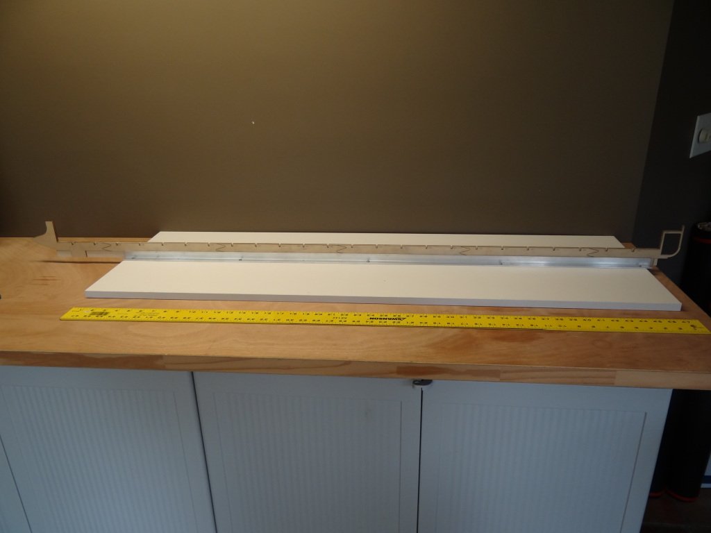
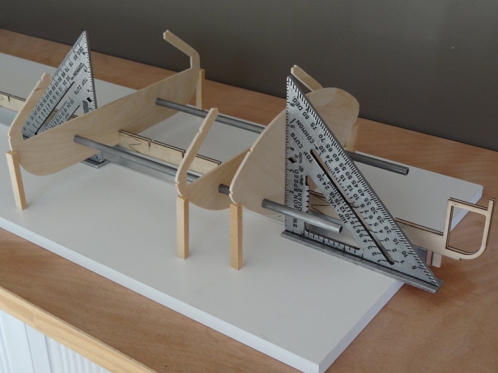
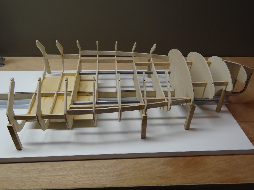
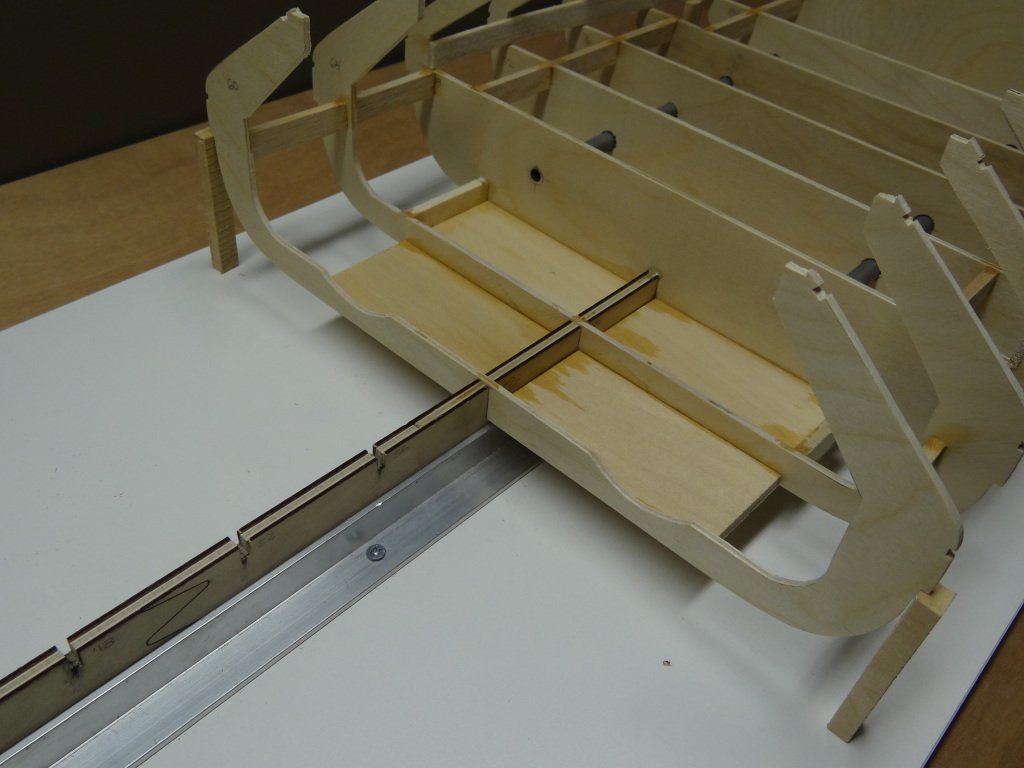
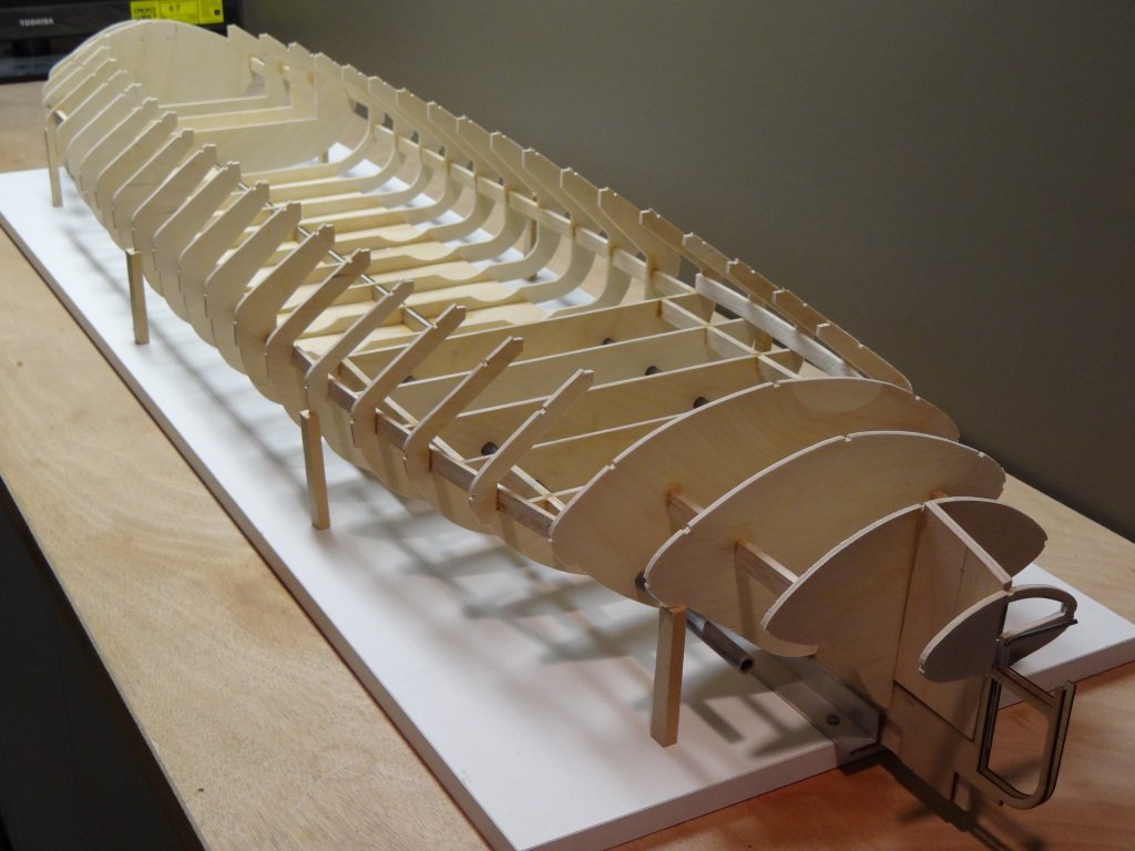
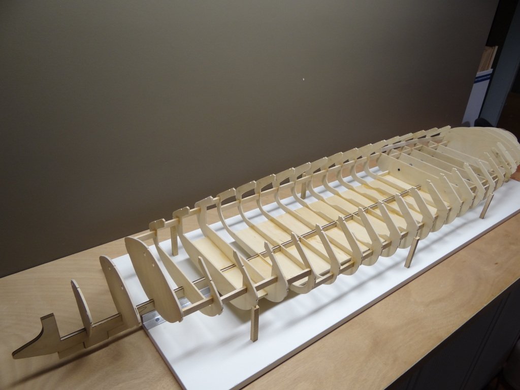
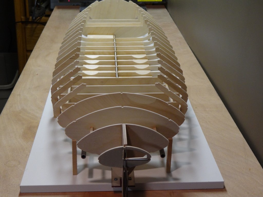
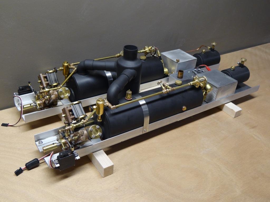
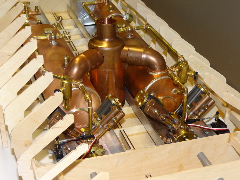
-
 Civil War Ironclad, USS St. Louis - !:24 Sequence of Assembly for USS St. Louis Model Rev C Notes: Rev A: This revision modifies Steps 5 thru 13 to permit direct use of the NPS plans to locate the structural elements yet allows installation of tempered hardboard sheets to add longitudinal stiffness to the lower hull structure. Rev B: This revision adds Steps 14 thru 18 with details for constructing and installing the hurricane deck as a removable sub-assembly. Rev 😄 This revision adds refinements to the sequence of assembly which were developed during model construction thus far. 1. Make a copy of sheets 3 & 4 of the "USS Cairo" National Park's Service plans at 1:24 scale and secure them to a sheet of 1/8 inch thick tempered hardboard. 2. Fabricate the three keels with scarf joints necessary to achieve about 4" longer than plan apparent length. Secure them directly on sheets 3 & 4 of the NPS hull floor plans with several 1/8" wood screws. (The keels will be trimmed to their final lengths in Steps 6 thru 9. 3. Fabricate all full and half frames up to the gun deck level chines using the three assembly jigs, locate them to the plans using small try-squares, and secure them to the keels with "Titebond III" wood glue and .052" diameter treenails in .055" holes. Place temporary wood support strips, which are the same thickness as the keels, under the lower frame floors at their outboard edges. (Do not glue or treenail the frames to these strips) Make a dozen or more wooden combs about 9" long by 1" wide by .25" thick which are dadoed to the "room and space" dimensions of the lower hull framing. Use these combs to temporarily locate and support the outboard ends of the frames as they are being secured to the keels. This is especially important for the aft half frames at the paddle wheel opening since they are only attached to one keel at this juncture. (By overlapping these 9" combs most of the hull structure can be made very rigid in preparation for installing the keelsons, deck clamps and other longitudinal structural members.) 4. Make the five keelsons & port and starboard gun deck clamps and secure them to all frames. 5. Attach about 6 temporary spreader beams, especially at the stern where the hull is split into two booms between the port & starboard gun deck clamps to maintain the lower hull shape. 6. Invert the partially completed hull structure and support it on jig locators to the inside of the hull floor timbers. 7. Make two longitudinal strips of 1/8-inch tempered hardboard approximately 4.5 inches wide which will fit snugly between the 3 keels and secure them to the lower surface of the frames with glue and treenails. 8. Add the cant frames, bevel the frames of the bow and stern to achieve a faired surface on the lower chine and install one or two rows of planking along the lower edge of the chine. 9. Make two additional strips of 1/8-inch tempered hardboard which abut the outer edges of the port and starboard keels and trim them to the outer surface of the lower chine planking. Secure them to the frames with glue and treenails. 10. Return the model to its upright position and install portions of ceiling, floor planking and longitudinal stanchions. 11. Frame and plank the waterway leading to the paddlewheel. 12. Add hull mounting provisions for the engines, paddlewheel and other machinery. 13. Add selected portions of the gun deck beams and planking which provide support for the armament while maintaining desired visibility to lower portions of the hull. 14. Based on further research of contemporary Civil War photographs we are convinced that unlike the flat decks shown on the NPS "USS Cairo" plans, the hurricane deck actually has a significant round-up (camber) of about 6.5-inches or .27-inches & a 15-foot arc at the 1:24 scale of our model. For accuracy this deck will be fabricated as a sub-assembly directly upon sheets 7 & 8 of the NPS plans and subsequently located over the lower hull structure and attached via the upper casement frames with removable pins thereby providing good internal hull access throughout the remaining model construction. The lower surfaces of the deck beams will remain flat since the distance between the gun deck planking and hurricane deck beams is over 7-feet and therefore an additional 6.5-inches on centerline would have been an unnecessary expense. 15. Make the 43 hurricane deck beams (carlines) from hard maple stock with identical the round-up (camber) formed into their upper surfaces using a special sanding fixture for the 15-foot radius mounted on a 4-inch table equipped vertical belt sander. 16. Construct the hurricane deck consisting of the port and starboard carline clamps (deck clamps), deck beams, and additional longitudinal framing members for the stacks, skylight, and wheelhouse. The present plan is to apply deck planking to at least one side (port or starboard) and additional selected planking to be determined later. 17. Locate the hurricane deck sub-assembly above the lower hull assembly on temporary supports or internal hull bulkheads while installing upper casement frames which are permanently fixed to the chine knuckles and pinned to the hurricane deck beams. 18. Frame in the gun ports and apply selected exterior planking to the upper casements. Temporarily un-pin and remove the hurricane deck to provide access for installing selected upper casement ceiling. 19. With the hurricane deck removed, continue with installation of the bulkheads and partitions around the wheelhouse, cabins and boilers and any other features on the gun deck. Method used to Construct the Lower Hull Frames (Rev A).doc Snap26.bmp Snap27.bmp Snap28.bmp Snap29.bmp Jig #3 Set-Up and Procedure for Use 26 Mar 2015.doc Method used to Construct the Lower Hull Frames (Rev A).doc Snap1.bmp Snap2.bmp Snap3.bmp Snap5.bmp Snap6.bmp Snap7.bmp
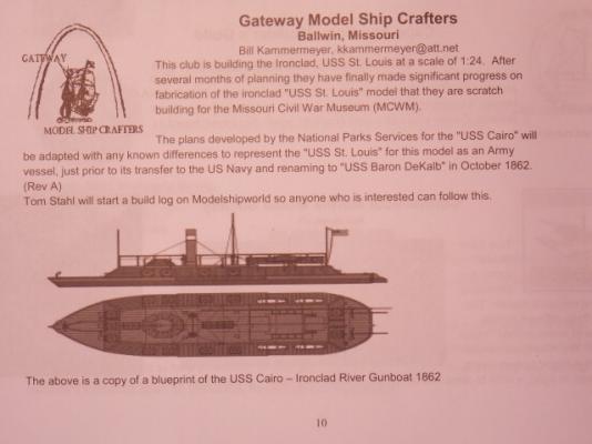
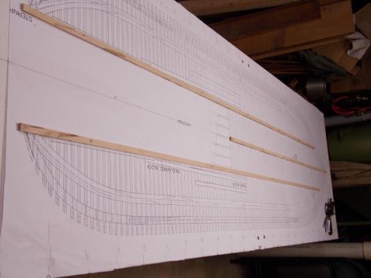
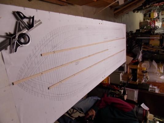
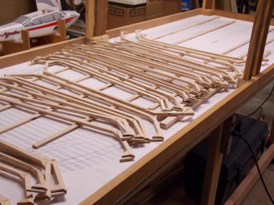


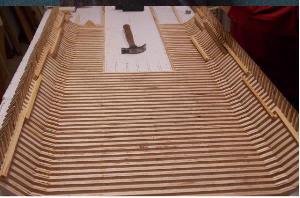
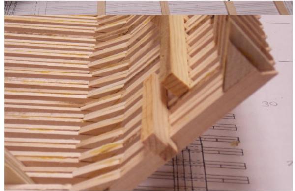
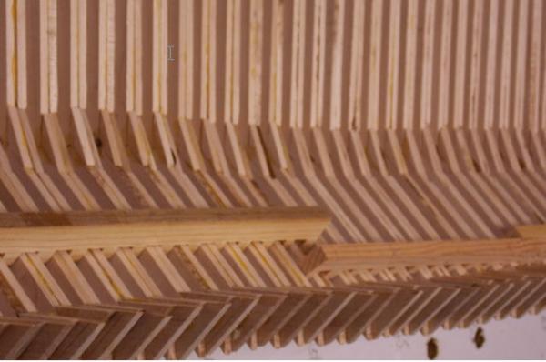

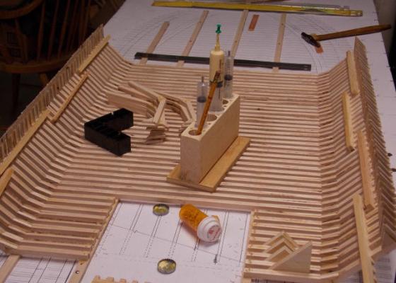
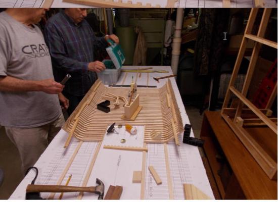

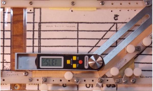

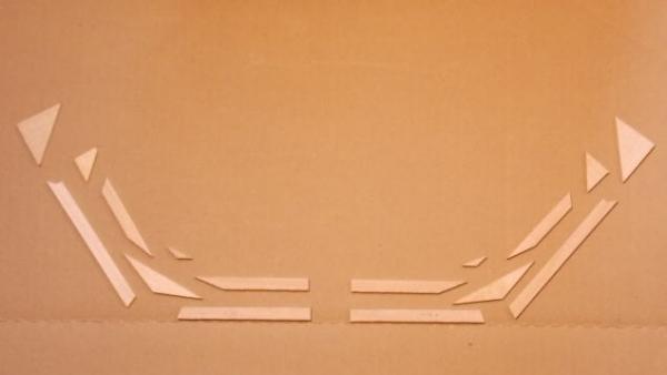
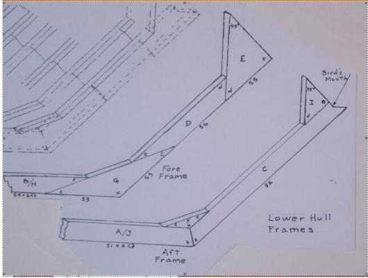


-
 A few days ago, while surfing the forum, I came across a very neat build of the Waratah, an HMV card kit. I pay a lot of attention to card models because I have found that I enjoy building them quite a lot. This set me to looking for HMV kits, and @ccoyle showed me where you could get them on Amazon. While looking at those, I discovered the Orel card kit of the Solferino (Magenta’s sister ship) which I had to have. It is in 1/200 scale, which is very small. I like larger scale models, and 1/72 is very convenient. At first, I wanted to just triple the size of the kit. Then I started doing research. Solferino is one of two Magenta-Class Ironclads. They were broadside battleships. Essentially they were armored versions of conventional 2-decked ships of the line. They struck a chord in me and I decided I needed one, or as it turns out, both of them, lol. They are very neat looking vessels. I started my research by going to Wikipedia, which led me to the original builders plans, hosted by the French Navy’s Historical Office in .tif format, which regrettably won’t display on the forum. I like builders plans, they are fun to develop models from. I will be building Magenta from the builders plans, difficult, but fun for me. The French Musee De La Marine has a model of Solferino which I will also be using for reference (these are from wikimedia commons). I am specifically building Magenta because I will also be building the kit of the Solferino whenever I get it and I do not like building the same ship twice. I have not yet decided on the building material yet. I may build in card or cardboard, or I may build in wood. I will most likely make the final decision on the day I cut the first piece, which will be shortly after I finish the Victory. Actual construction will likely be starting in a few months because I need to finish Victory, do thorough research and print the plans/update them with the findings of my research. Thanks for visiting!
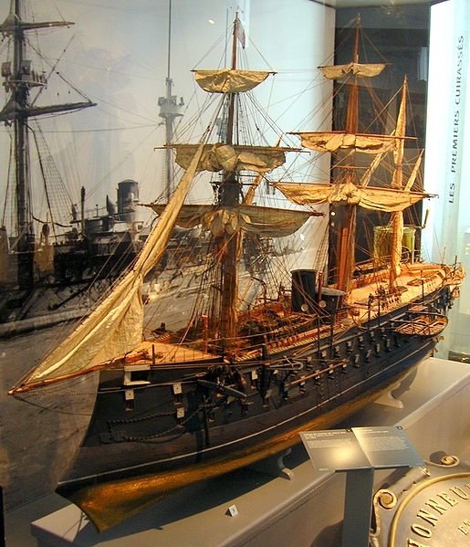
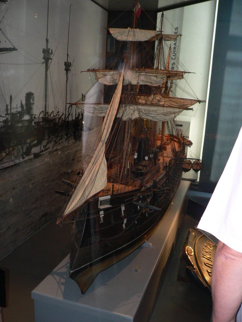
- 104 replies
-
- 20
-
-
 I just joined the local Men's Shed - this is a common set-up in Oz, where men can get together, talk about men's stuff, tell a lot of lies, and make stuff. The local one is in the woodworking section of a local high school which has now been converted to a community centre, and has an amazing array of equipment and facilities - carpenters' benches, planes, chisels, drill presses, bench and drop-saws, lathes of various sizes, thicknessers, disc sanders (my current favourite!) etc etc. As it's a fairly informal community group they're always short of funds and they make things to sell, to fund their activities - timber cutting boards (bread-boards), birdhouses, that kind of thing. It occurred to me that (not really wanting to make bird-houses, though I might be persuaded to make possum-boxes to put in trees to provide homes for the local wild-life), I should do something more in line with my own interests. Which led to the HMVS Cerberus, a coastal monitor built in England in 1870 for the fledgling navy of the colony of Victoria, Australia. https://www.navy.gov.au/hmas-cerberus-hmvs Fortunately, I was able to find this on-line: Looking at the plans, I realised she could be made quite simply as a "bread and butter" model, cut from 10mm sheets of pine with my new Precious (scroll saw), with only a little fiddly work to do the additional bits of pieces - the masts and skylights etc (which I will probably make out of bamboo kitchen skewers of various sizes.) I blew the plan view up on the photocopier, and glued the copy onto a bit of pine I had lying around. So, off I went, and here is the beginning of the build. The turrets were cut from the same sheet of pine, using a hole saw attached to my electric drill. More to come. Steven PS: Dan Vadas (sadly missed) made a model of the Cerberus out of card - you can see the build log if you do a search).
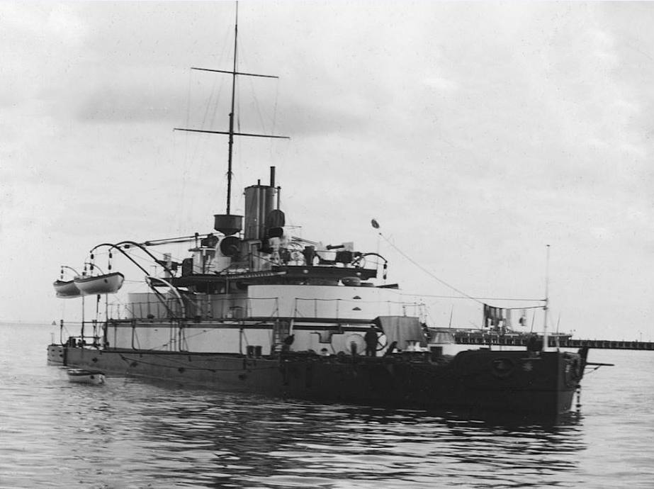
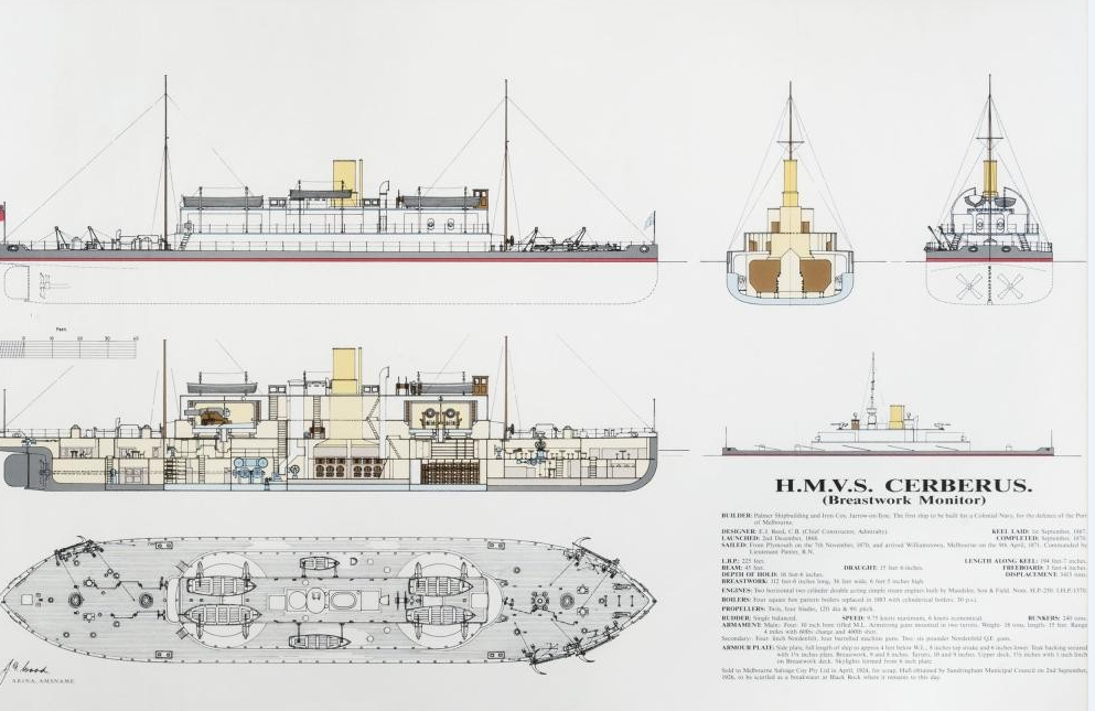

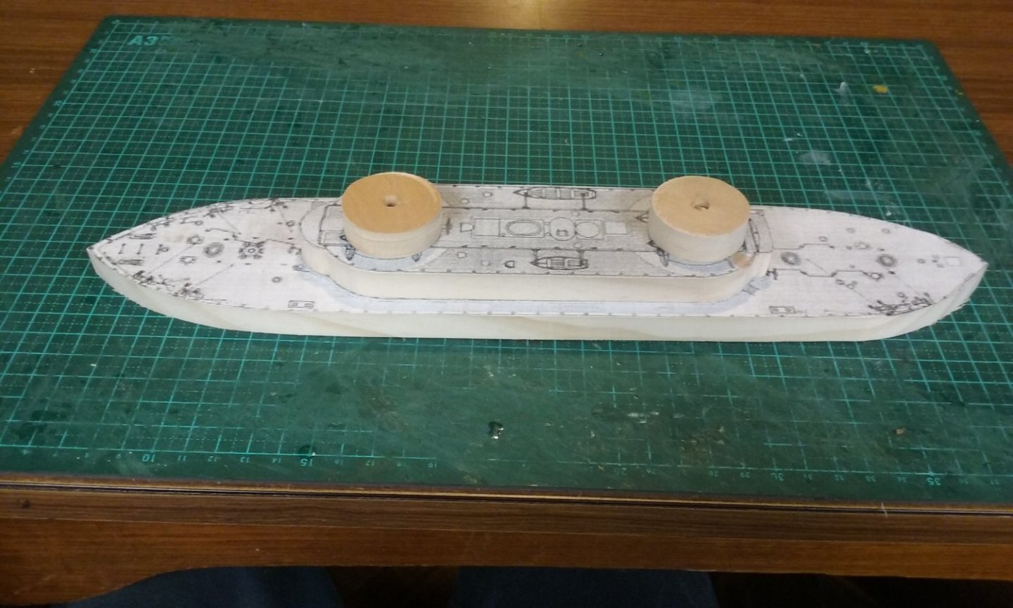
- 28 replies
-
- 12
-
-
 Hello Everyone, Welcome to the beginning of my build log for my first scratch build model. I recently completed work on the 1884 Packet Steamer Chaperon, which was my first attempt at a build log, and I enjoyed it so much that I wanted have another go at it. The comments and suggestions and overall conversation on the build was way more than I had expected. There are so many people out there with so many great ideas that helped along the way. Not to mention the knowledge I gained from the research. For this build I will be taking on the City Class USS Cairo American Civil War Ironclad as she was shortly before her sinking in 1862. I have been in love with this particular ship since my first visit to Vicksburg NMP back in 1984. Something about the mystique of the recovery of a sunken ship and the history of those who lived aboard is just fascinating. And, since there are no large-scale wooden model kits out there for this particular ship, I figured this was the perfect opportunity to scratch build one. My plan is to build this model in 1:48 scale using the Bob Hill plans, the USS Cairo HSR documentation from the Vicksburg NMP, and several other builds, especially the build log for the Civil War Ironclad USS ST. LOUIS by the Gateway Model Shipcrafter's Guild. This is an exceptional build and their extensive research has found many discrepancies with the USS Cairo HSR and I hope to “borrow” some of their research findings to accurately build my representation of the USS Cairo. I won’t be building out a whole lot of interior details, with the exception of what can be see through the gun ports, skylights and deck vents. I will probably build out the tops of the boilers, flue, capstan, and possibly simulate the engines. I haven’t quite determined what material I will use for the iron plate cladding, but for the railroad irons on the forward and aft casements, I plan on using HO scale model railroad track to try and make it look as authentic as possible. Without boring you with too much of a detailed history of this ship, here is a little background info on it: The USS Cairo, along with her six sister ships (Carondelet, Cincinnati, Louisville, Mound City, Pittsburg, and St. Louis) were commissioned by the U.S. Army (later transferred to the U.S. Navy), designed by Samuel M. Pook and built by James B. Eads at the Carondelet and Mound City Shipyards in 1861. USS Cairo was 175’ in length with a 52’ 2” beam and drew only 6’ of water. Not very deep for a 512-ton heavily armored ship. Ironically, she was sunk by a Confederate “torpedo” on December 12, 1862 in the Yazoo river while on a mine clearing mission. The USS Cairo wreckage was located in 1956 and finally raised from the mud in 1964. She sat in neglect at the Ingalls Shipyard in Pascagoula, MS for several years, until 1977 where she was transported, restored and placed on permanent display at the Vicksburg National Military Park in Vicksburg, MS. This will definitely be a learning experience for me, so if you would like to follow along, please pull up a chair and feel free to offer up any suggestions. I am always open to new ideas and constructive criticism. If you see something that I am doing wrong or see a better way to do something, by all means, please let me know. I welcome the input. As she sits today (well, six years ago when I took this picture): -Brian
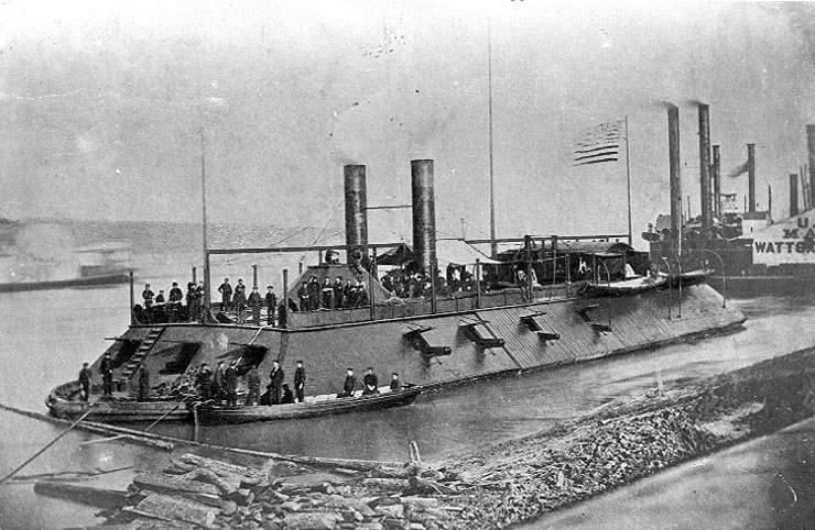
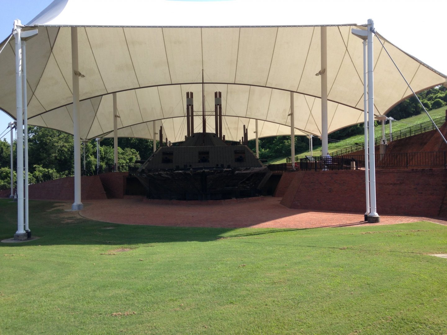
- 739 replies
-
- 15
-
-
This is an accessory build to my Magenta in the scratch build section. Solferino was a Magenta-Class Ironclad Broadside Battleship. I am using this model primarily for research purposes, regarding locations and dimensions of deck fittings. I have the builders plans for the Magenta (Solferino) already printed out in 1/72 scale, but those have very little in the way of deck furniture and nothing regarding weaponry. I am going to use this model, combined with the excellent photos that a forum member very generously sent me of the model in the Paris Maritime Museum, to fill in those gaps. Secondarily, this will make a nice desktop model for my office. The kit is an Orel Card Kit: It will eventually look like this: I have never built a card ship kit, but I have built two card ships from scratch following Ab Hoving’s most excellent Tutorial on building in card from scratch. If you haven’t read that tutorial, I strongly recommend it. It is what started me down the road to scratch building. This build will be interesting. I am looking forward to starting this model.
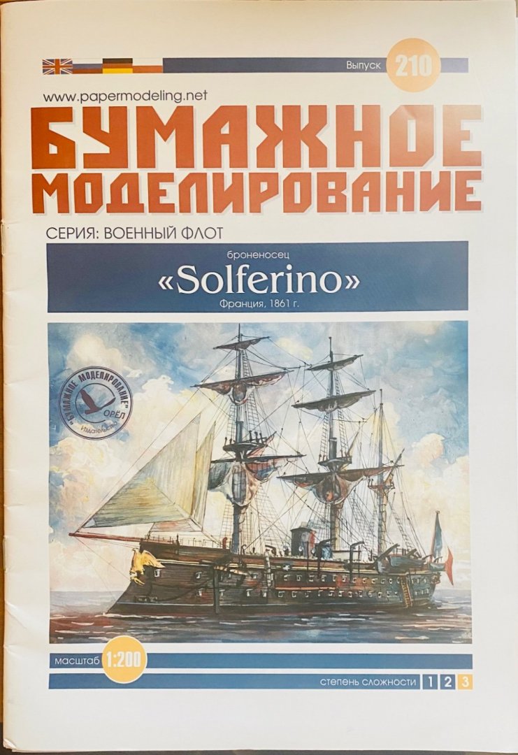

-
 ..plastic with wood decking
-
Hi all, I'm a big fan of pre-dreadnoughts , particularly ironclads. There's not a lot of kits available for these beasts, currently Cottage Industry Models offers some really nice 1:192 and 1:96 kits. The 1:96 kits are cutaway with full interior detail and I'll probably build one (CSS Tennessee) in the future. Other current manufacturers I am aware of are Flagship Models, Lone Star Models and Old Steam Navy (There are probably others, LMK). Most modelers are familiar with Verlinden Productions, a company that made some of the best PE and resin add on detail sets for armor and aircraft. Unfortunately, the company closed in 2016 so these fine products are only available from ebay, as NOS or from in-store inventory. What most aren't aware of is that Verlinden released a line of waterline 1:200 civil war ironclads called "North and South". This is an unboxing and quick look at their kit of the Confederate ironclad CSS Nashville. I purchased the kit from Dragon-Hobby on eBay for about $100 shipped. Here's a quick history and description from Wikipedia: "The ship was 271 feet (82.6 m)long overall, had a beam of 62 feet 6 inches (19.1 m) and a draft of 10 feet 9 inches (3.3 m). The side wheels were powered by two steam engines with a 9-inch (229 mm) bore and a 36-inch (914 mm) stroke. She was armed with three 7-inch (178 mm) Brooke Rifles and a 24-pounder howitzer. Nashville was laid down at Montgomery, Alabama because of the availability of riverboat engines there. Launched in mid-1863, Nashville was taken to Mobile for completion in 1864. Part of her armor came from the CSS Baltic. Still fitting out, she took no part in the Battle of Mobile Bay on 5 August 1864. She helped fend off attacks on Spanish Fort Alabama on 27 March 1865, supporting Confederate forces until driven away by Federal batteries, and shelled Federal troops near Fort Blakely on 2 April 1865. The ships retreated up the Tombigbee River 10 days later when Mobile surrendered. She was one of the vessels formally surrendered on 10 May 1865. Although never quite finished, she had been heavily armored with triple 2-inch plating forward and around her pilot house, only a single thickness aft and there had been some doubts expressed that her builders might have overestimated her structural strength. After a survey by a Union engineer, he determined that she was hogged when surrendered and was not strong enough to bear the weight of her full armor, and that she could not live in a seaway. Following her surrender, Nashville was laid up until 22 November 1867, when she was sold for scrap, her armor having previously been stripped for reuse in other vessels. Here's an artist's rendition from Google images: On to the kit... Packaged in a sturdy plain white box with a color label, the hull and parts bag were safely bubble wrapped and surrounded by foam peanuts. Here's the instructions: Here's some shots of the one piece resin waterline hull. No flash, bubbles or distortion. This is one of the nicest resin castings I've ever run across. The cast detail is crisp and the finish is smooth. The hull measures about 16" long, 4" wide (with paddles) and 4" tall (with smokestack). Here's the rest of the parts: Lots of sprues to saw off, but the overall detail is quite good. My kit was missing one cannon port cover, but there are extras included so no problem. One bottom edge of the paddle wheel cover is broken off, but the piece was in the parts bag and should re-attach with no problem. After a good cleaning, assembly should be pretty simple. A coat of proper primer and then she'll be ready for weathering. Ugly as she is, she should build up into an obscure but interesting model. Since these kits are out of production, they're getting harder to find but the good thing is that they can be found for a fraction of their original list price. In conclusion, this is a fine kit. Well cast, nice detail and relatively simple construction. This kit is in my build queue, and I'll start a build log when I begin construction.
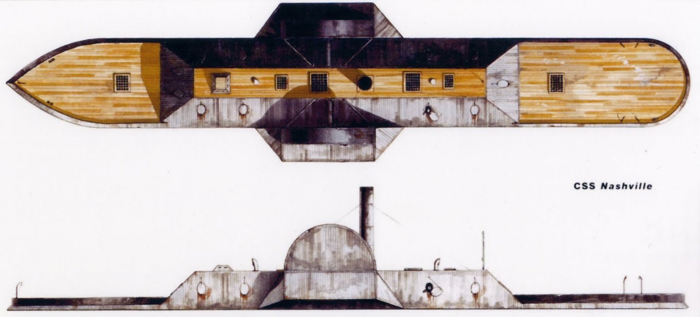
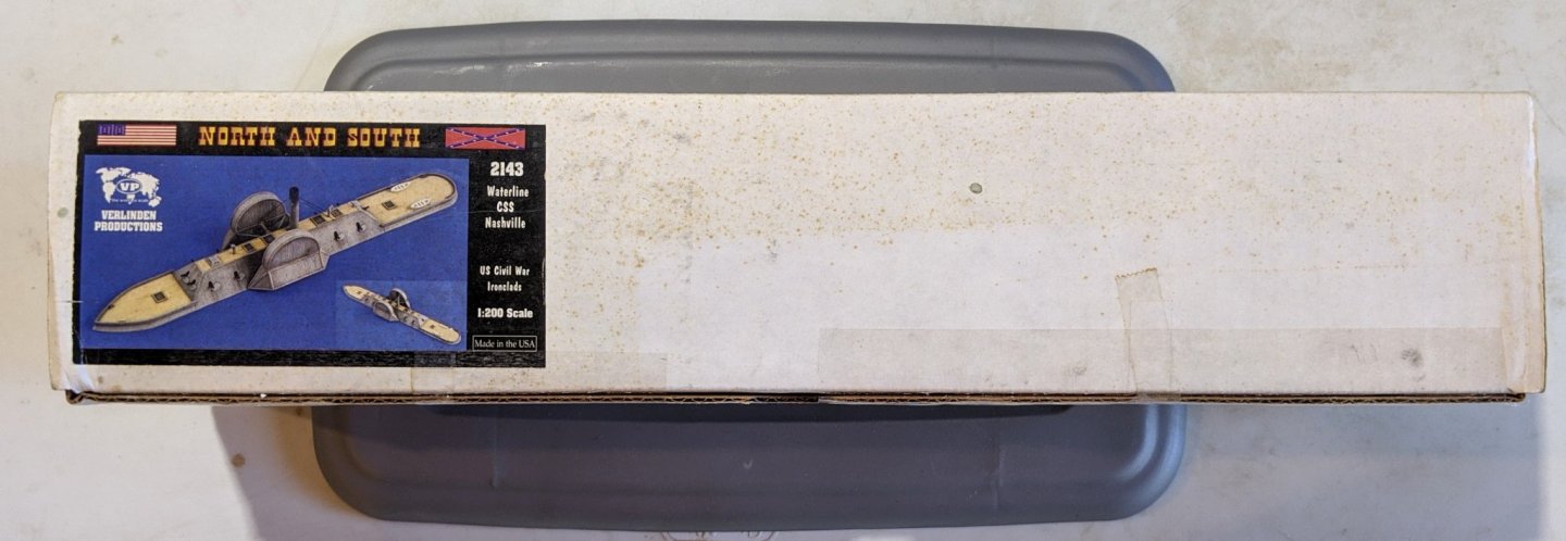


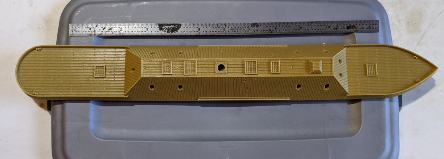
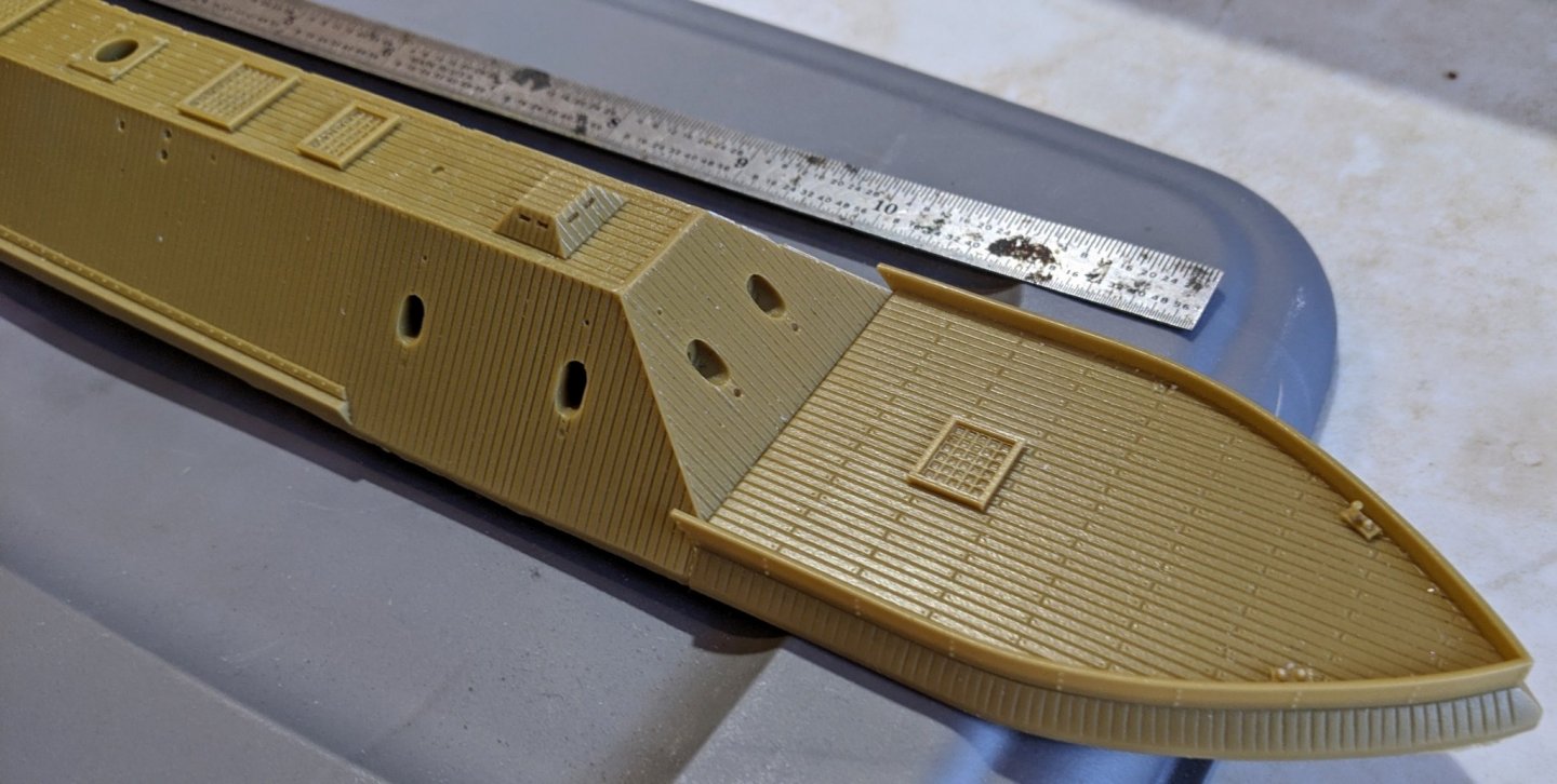

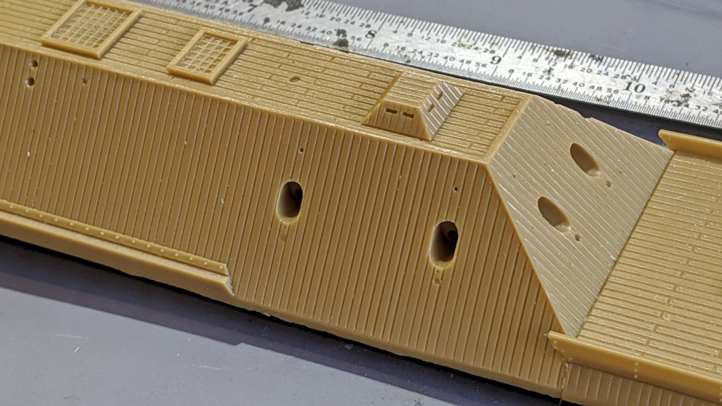
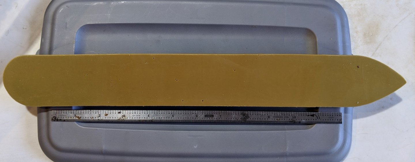
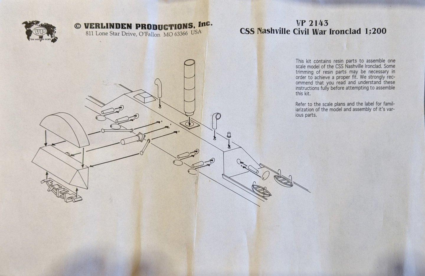
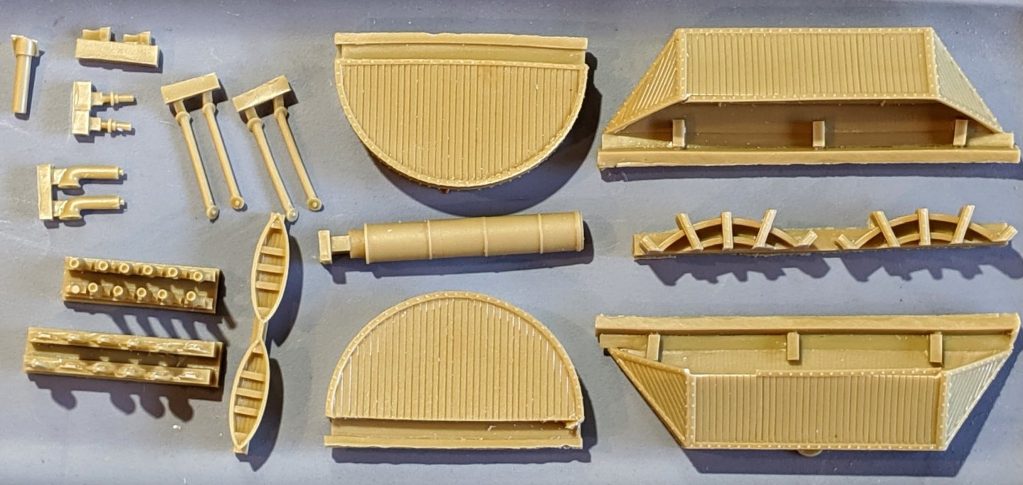
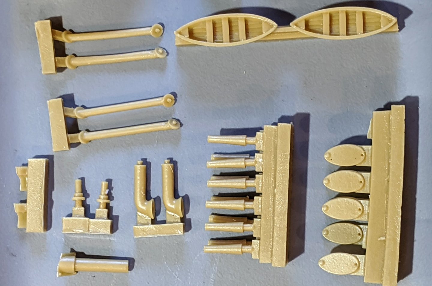
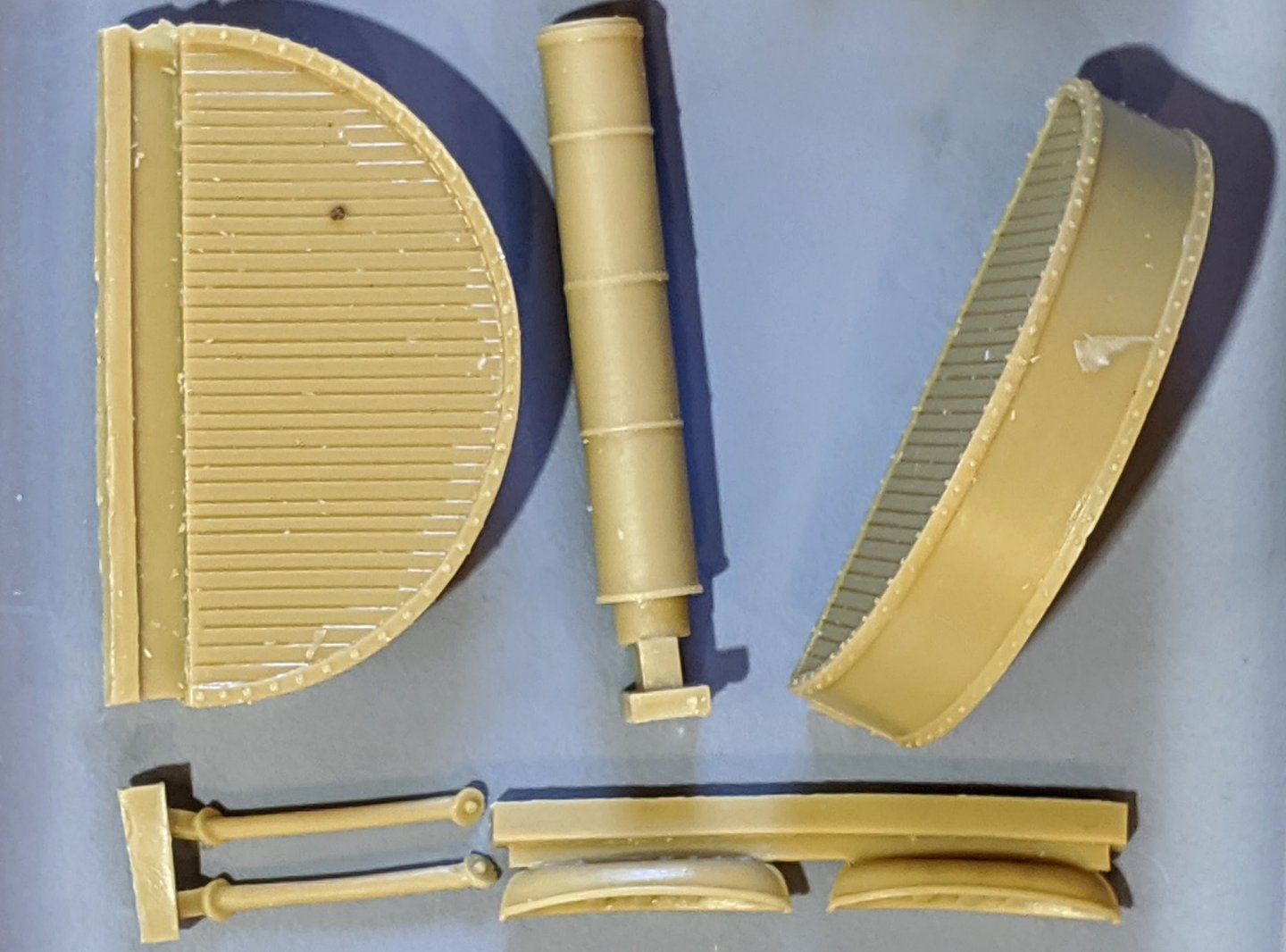
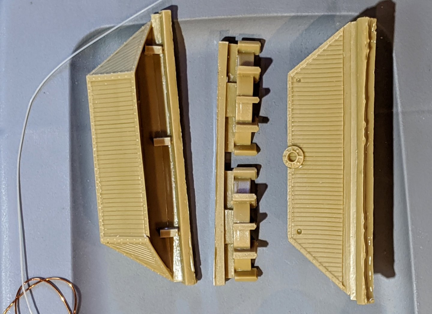
-
 C.S.S. Richmond was one of the earliest Confederate ironclads, having been laid down at the Gosport Navy Yard at Norfolk, Virginia, in March 1862, immediately after the completion of the famous C.S.S. Virginia (ex-Merrimack). Richmond was designed by John Luke Porter, who would go on to serve as the Chief Naval Constructor for the Confederacy, but completed under supervision of Chief Carpenter James Meads. Richmond embodied many of the basic design elements that be used, again and again, in other casemate ironclads built across the South in the following three years. When Union forces were on the verge of taking the Gosport Navy Yard, Richmond was hurriedly launched and towed up the James River, where she was completed at Richmond. Finally commissioned in July 1862, the ironclad served as a core element of the Confederate capital’s James River Squadron for the remainder of the war. Richmond, along with the other ironclads in the James, was destroyed to prevent her capture with the fall of her namesake city at the beginning of April 1865. This model is based on plans of the ironclad by David Meagher, published in John M. Coski’s book, Capital Navy: The Men, Ships and Operations of the James River Squadron, with modifications based on a profile of the ship by John W. Wallis, particularly regarding the position of the ship’s funnel and pilot house. Hull lines are adapted from William E. Geoghagen’s plans for a later Porter design for an ironclad at Wilmington, that seems to have had an identical midship cross-section.
- 4 replies
-
- 5
-
-
- Richmond
- Confederate Navy
- (and 4 more)

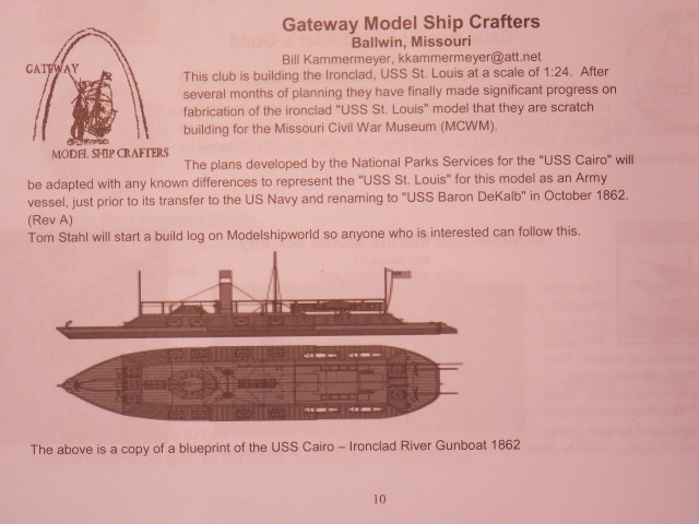


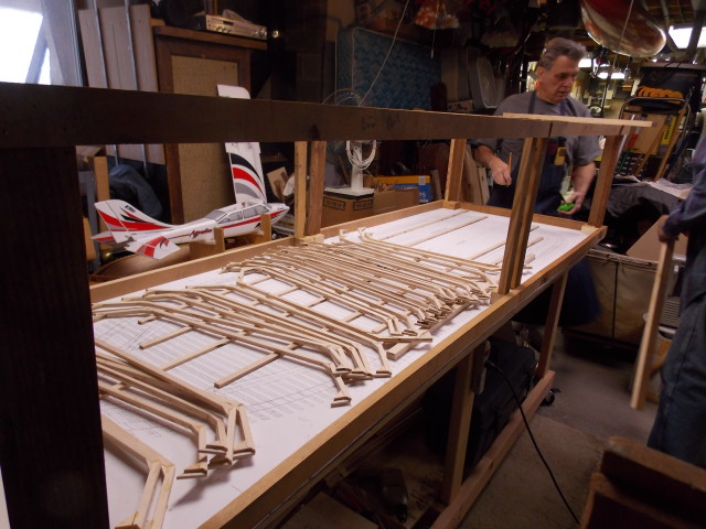
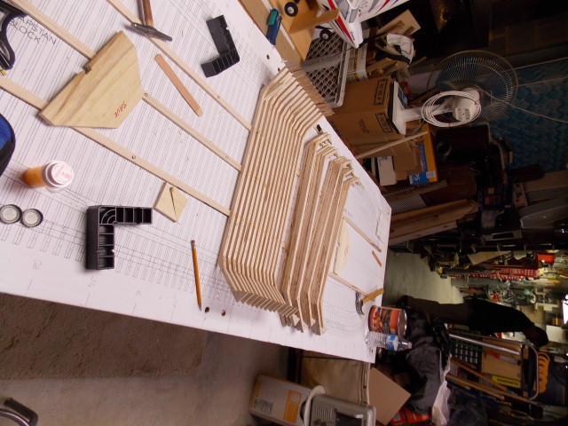
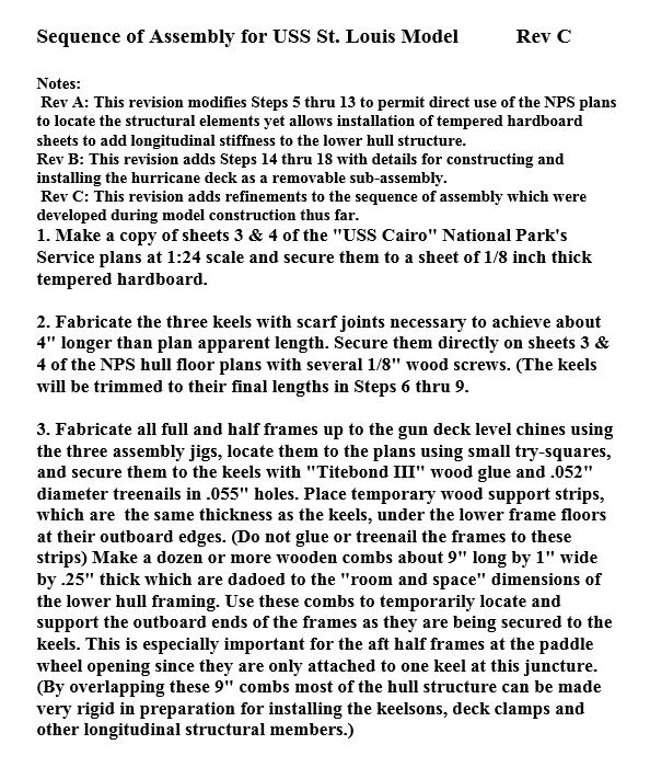

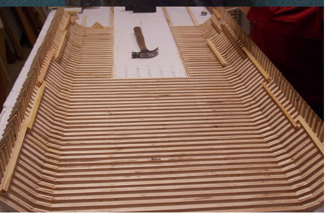


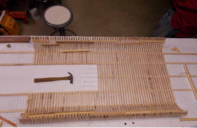

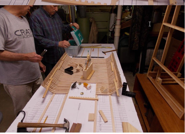


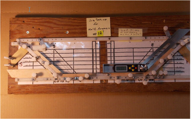
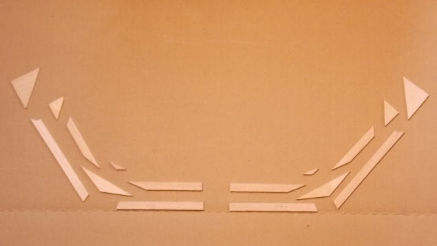
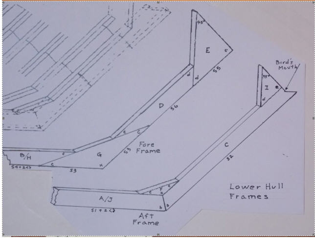
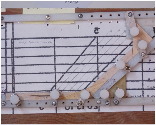


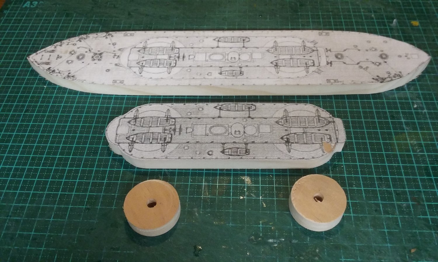

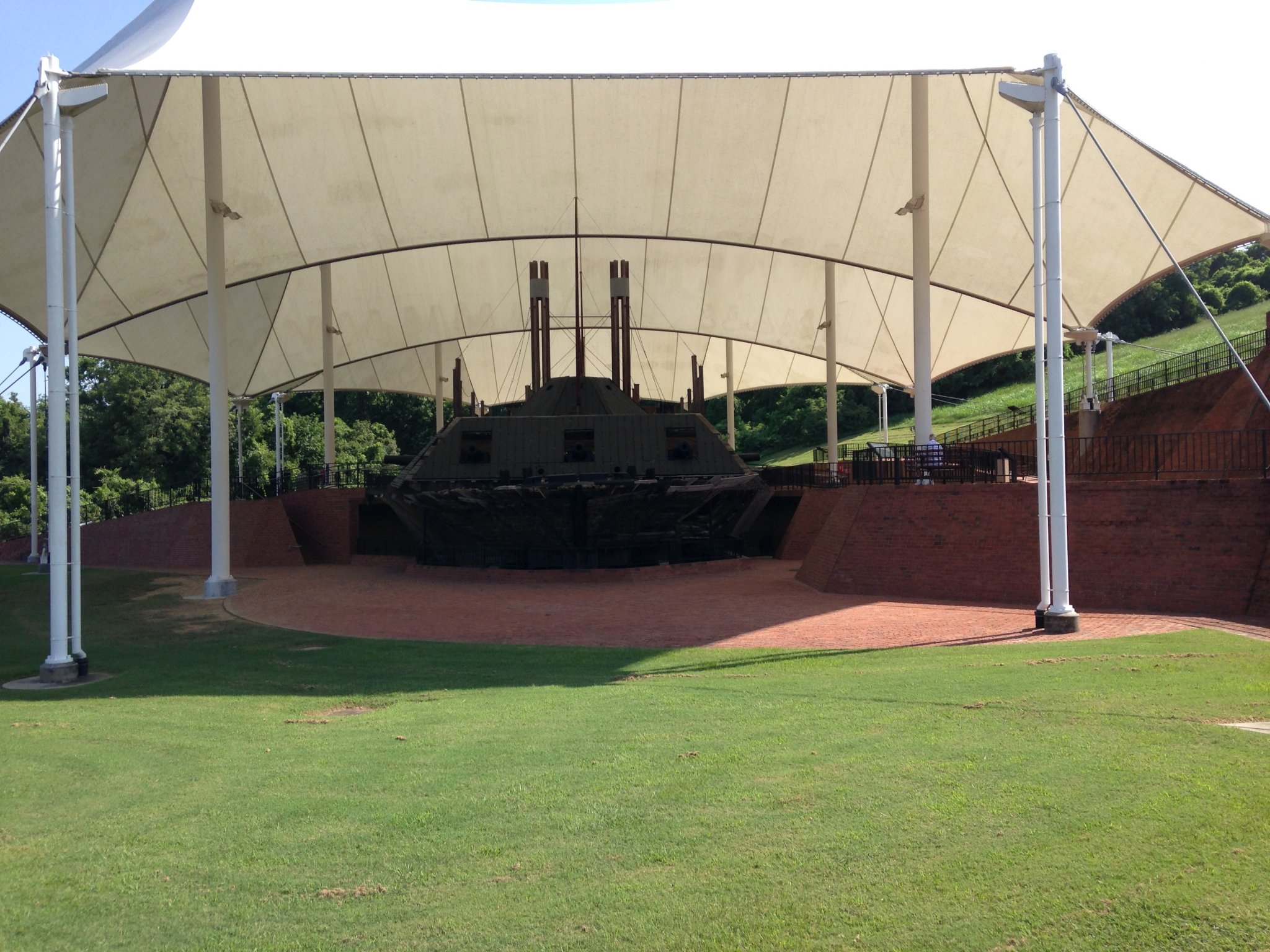

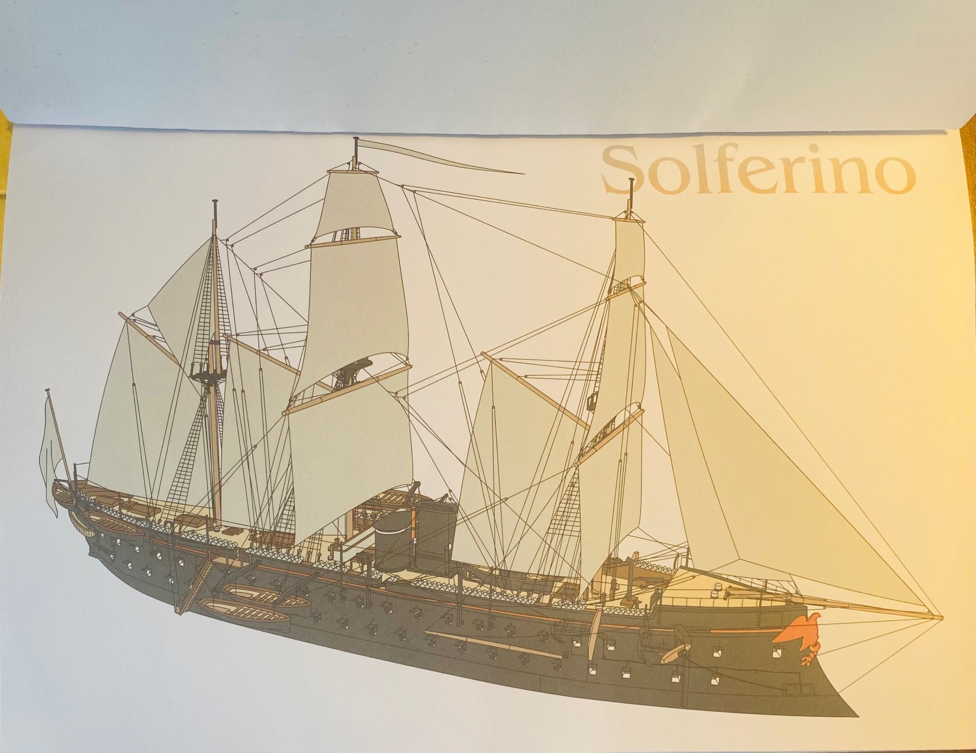

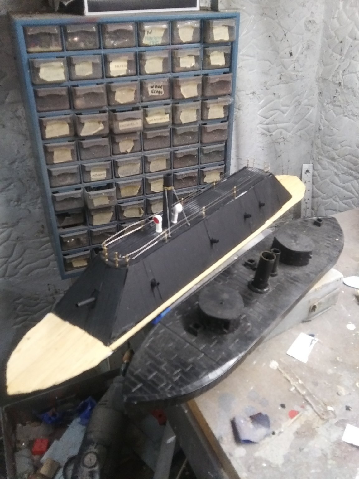
.thumb.jpg.2abae9c0194e4e915bb097b8a6d5c174.jpg)