dcicero
-
Posts
267 -
Joined
-
Last visited
Content Type
Profiles
Forums
Gallery
Events
Everything posted by dcicero
-
Thanks, Toni. I detached the lower batten and repositioned it. I didn't move it much. Moving it much lower really changed the sweep of the batten a lot. Last night, I got my replacement broad strake in. It looks much better. And I laid out the stealer.
-
Not liking the way the forward part of the broad strake looked in those photos, I decided to remove it and do it again. Doing it again, now, will save me a lot of headaches later because that defect will bother me throughout this whole process.


-
I've gotten a couple of messages saying my photos aren't visible. Can't explain that. I posted the URL to my OneDrive folder, but no matter. Here they are. Dan


-
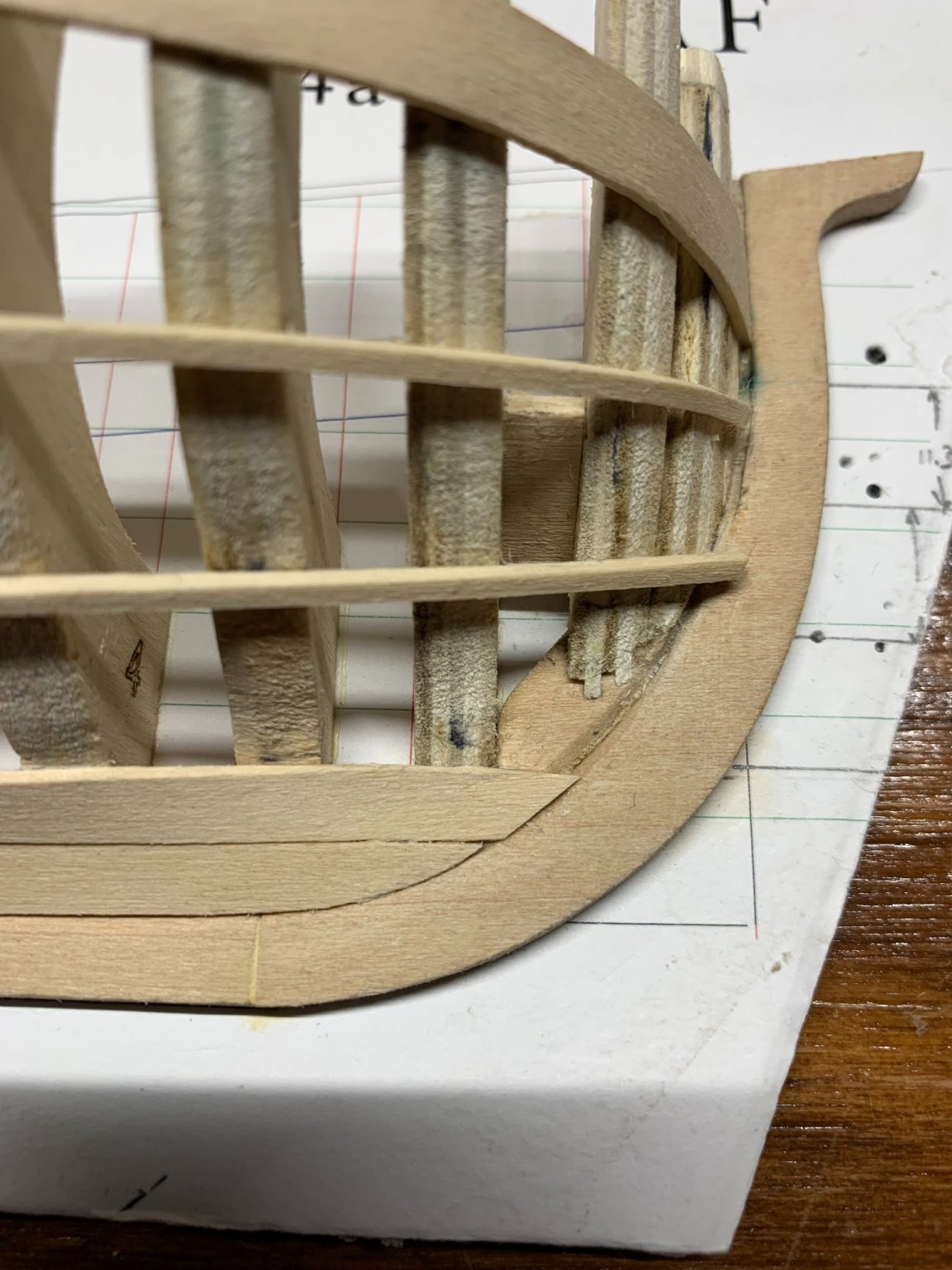
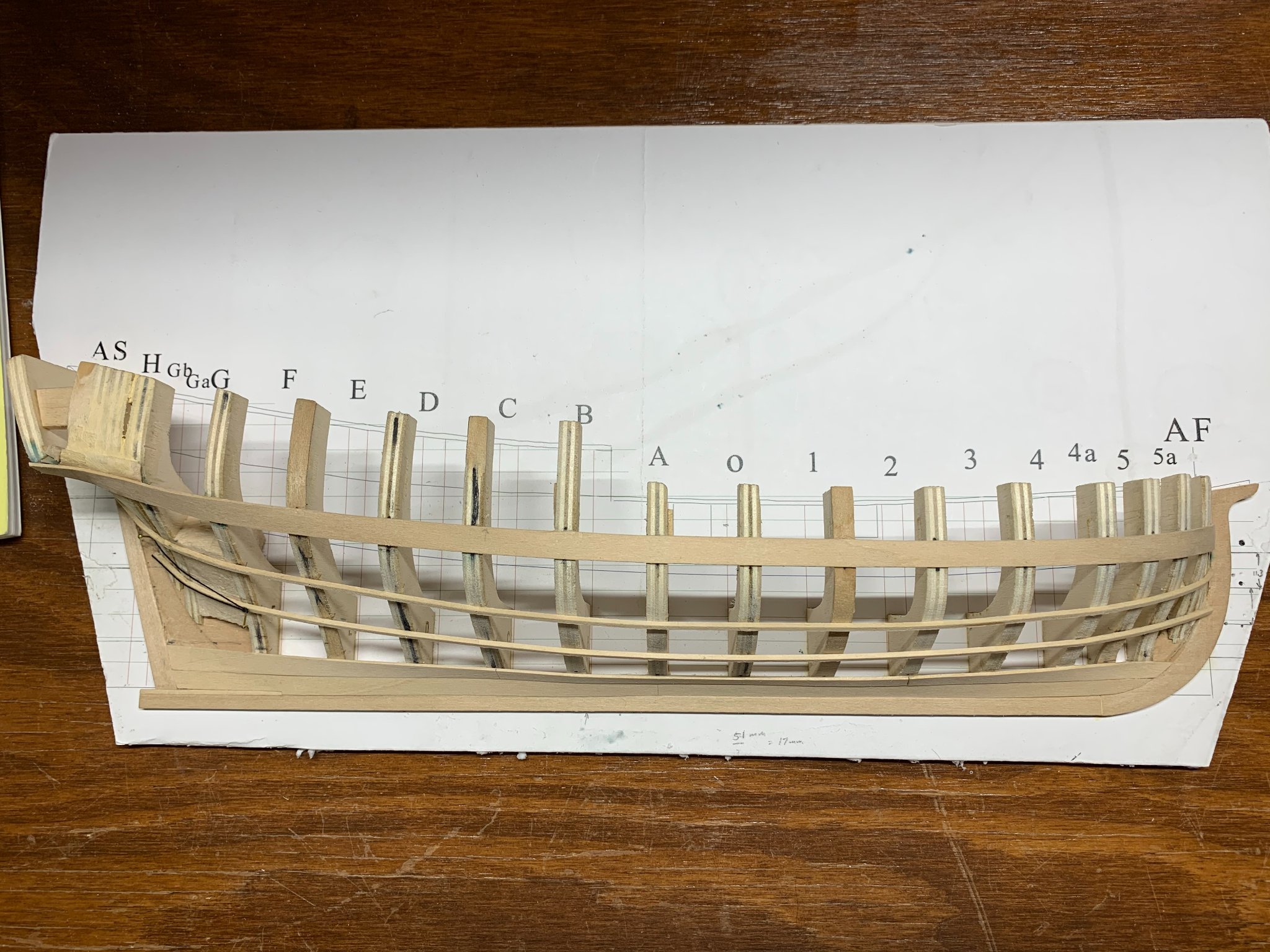
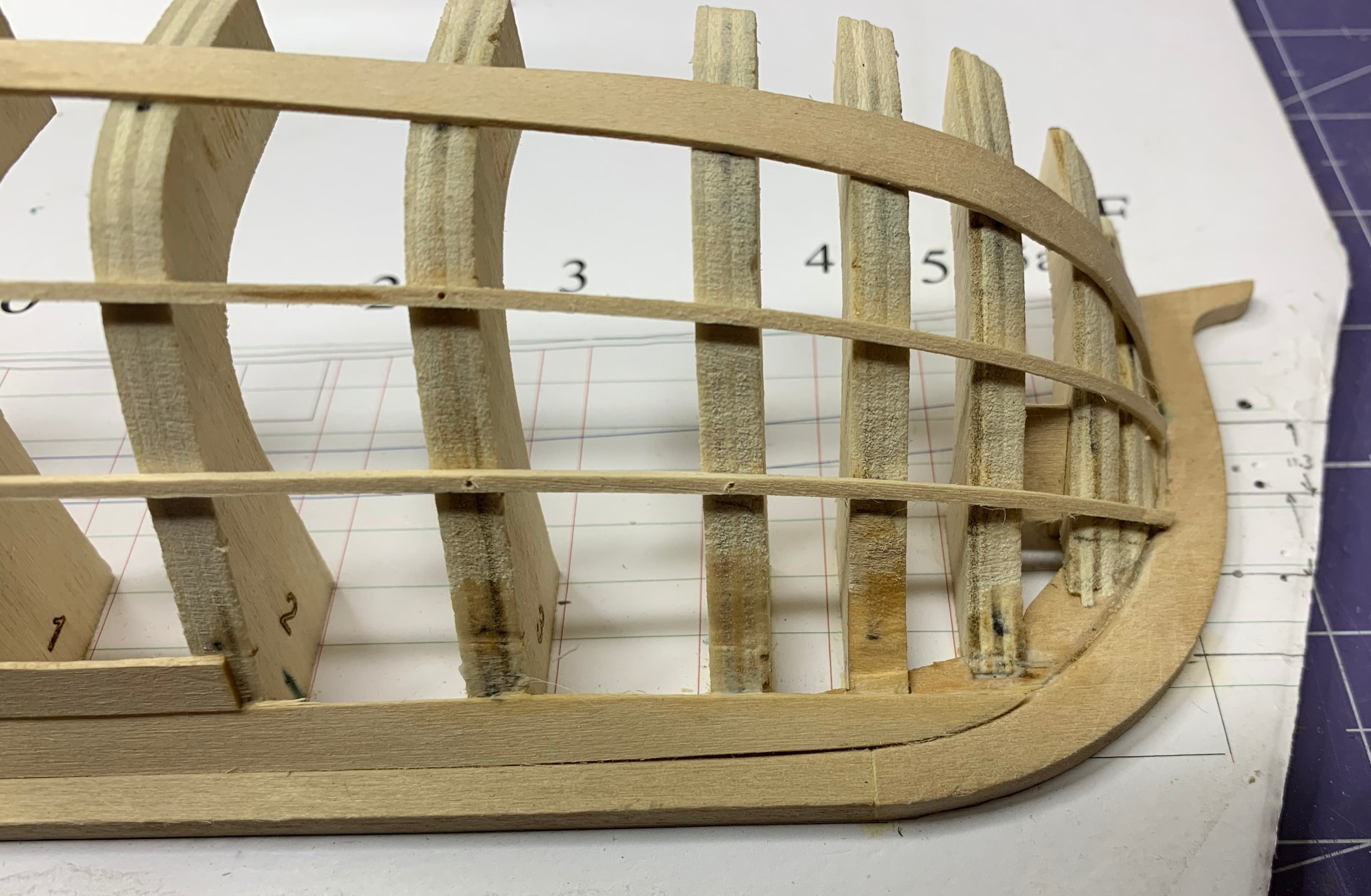
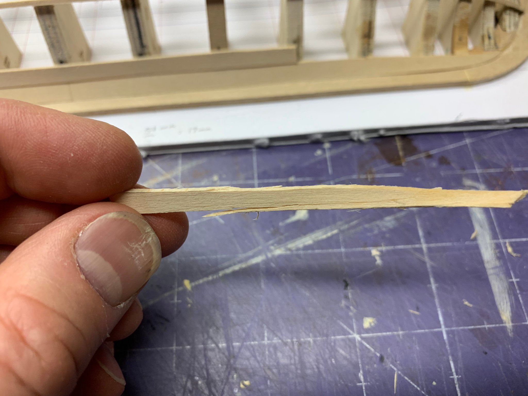
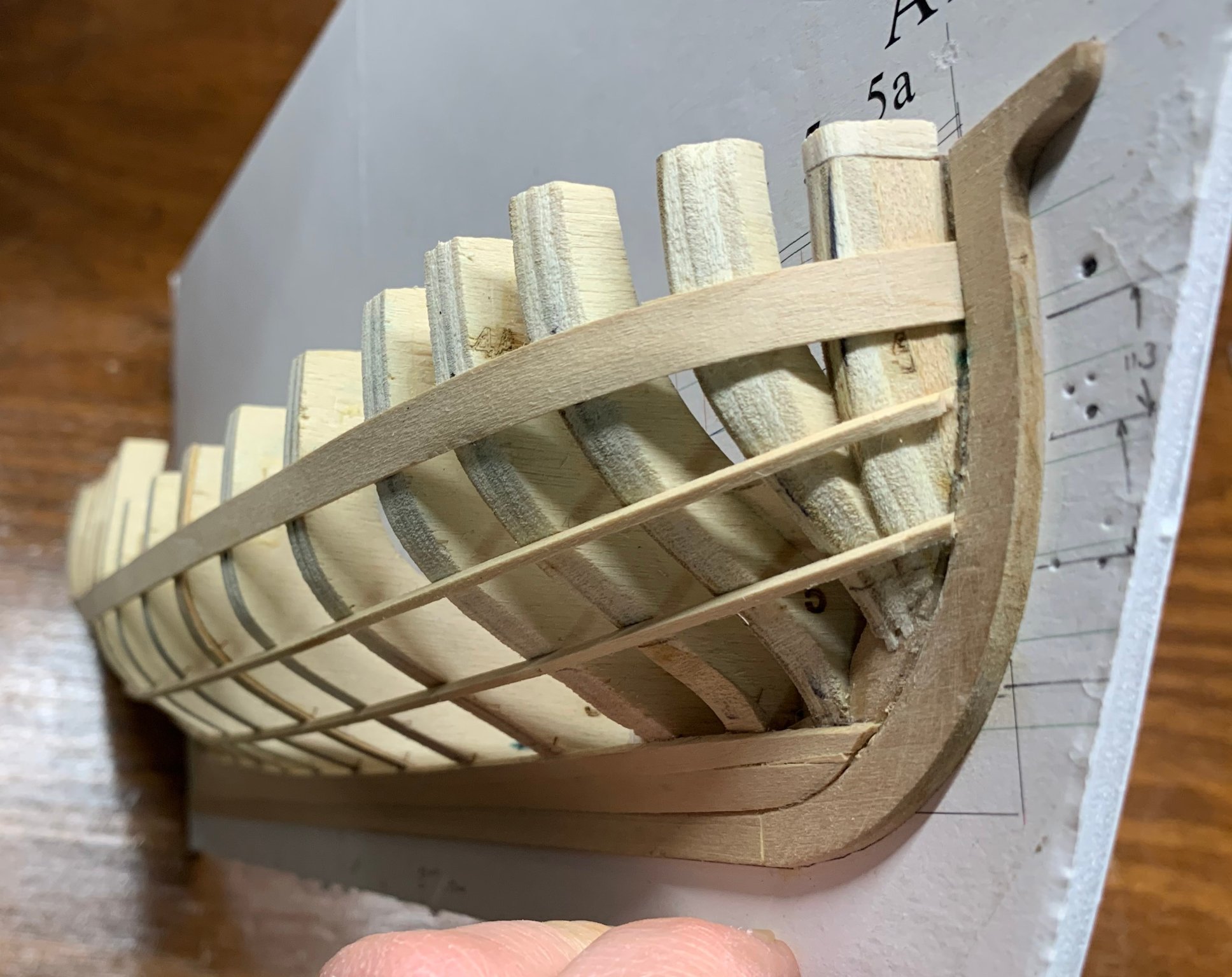
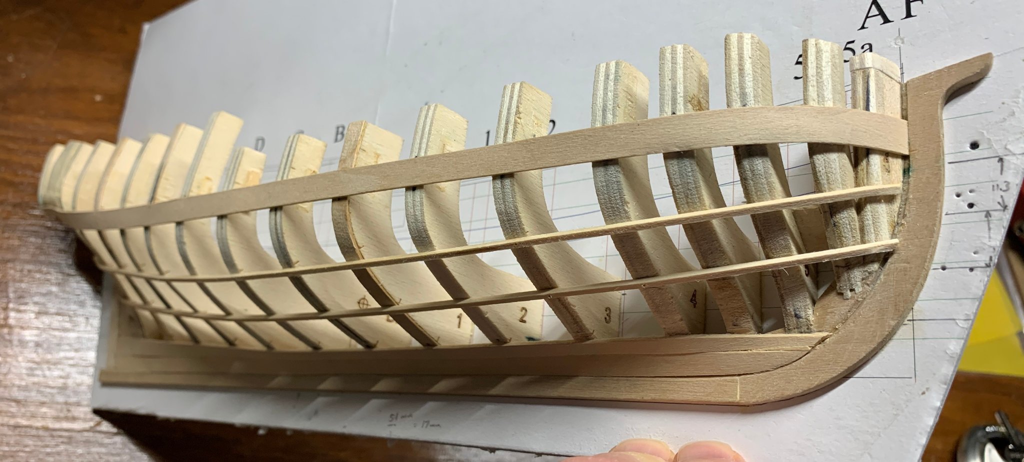
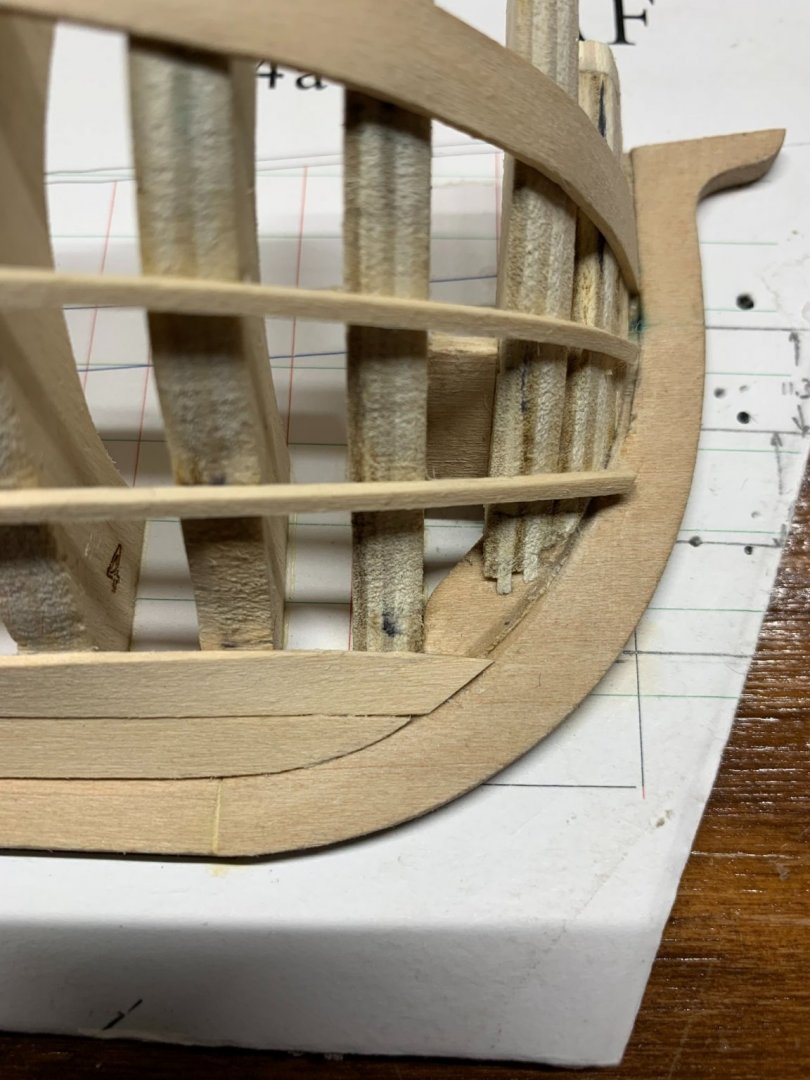
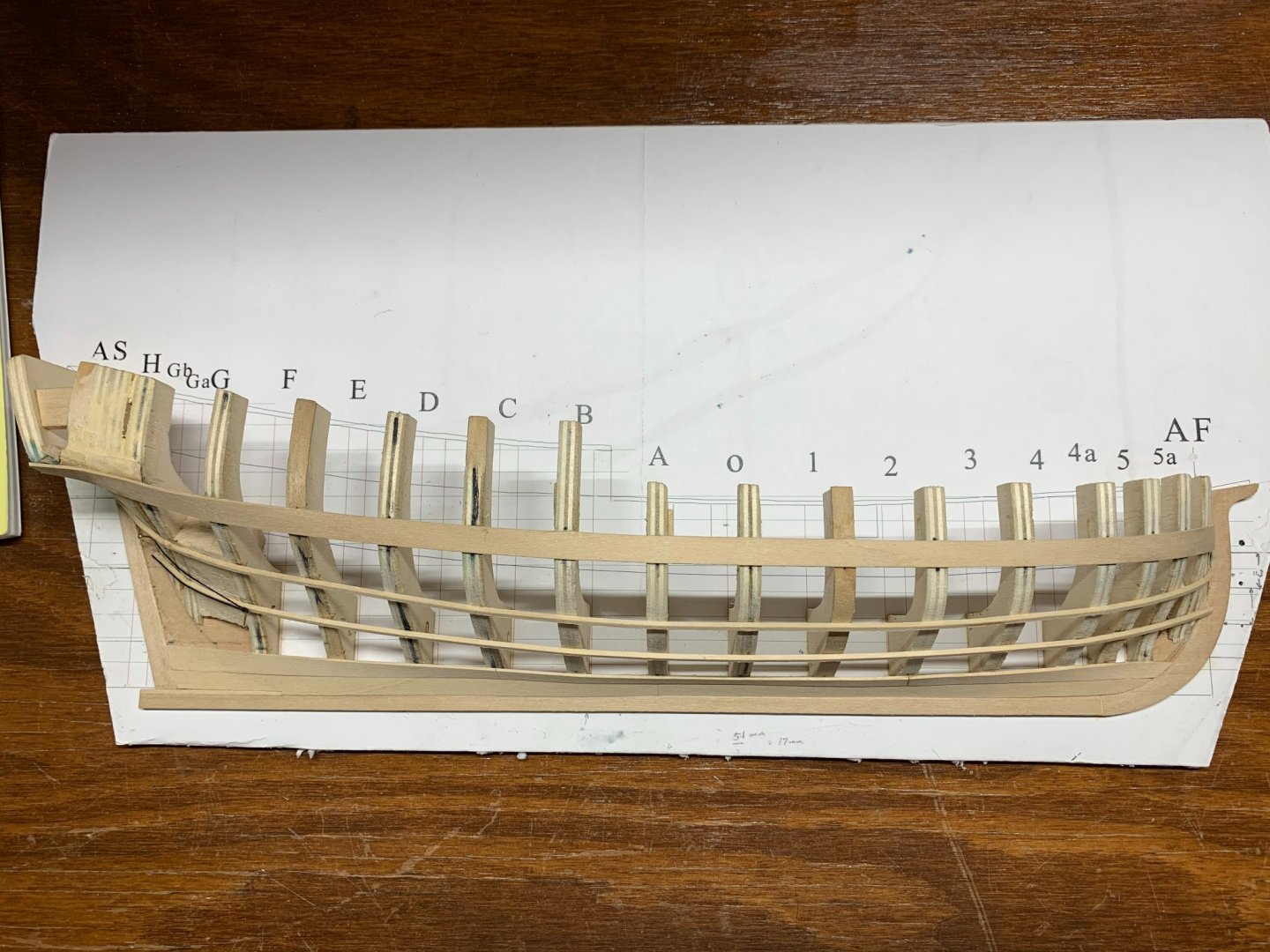
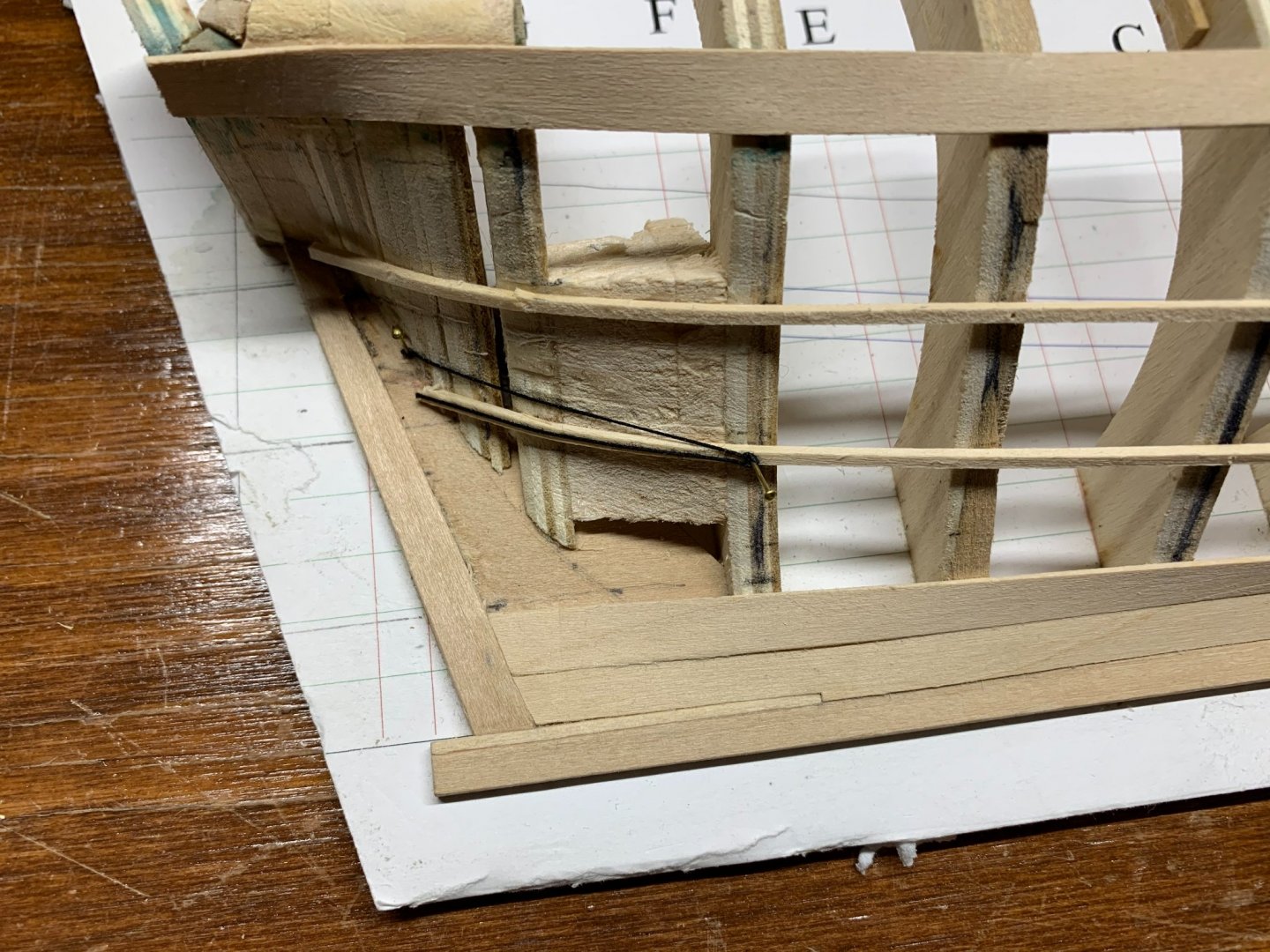
For everyone in the US, Happy Memorial Day! Just a quick progress update today. I've installed the planking battens. I used the technique explained in Planking the Built-Up Ship Model. That book recommends using 1/16" wooden battens rather than the string battens Toni recommended. Since I'd tried the strings before and had a tough time getting them to stay where I put them, I decided to pull some 1/16" strip wood out of my wood pile and see how they would work. I like the results. I tacked them to the frames with the smallest brads I had, which kept them in place. I wetted them slightly to get them to bend around the bow and just moved them around until I got a "pleasing run of planking." I'm happy with the results, but let me know if I shouldn't be! I struggled with the broad strake. Once I had it installed, I had to do some trimming on the upper edge to get a clean line, fore and aft. And you can seem in the bow, that I had a little splitting happen. It's a lot more noticeable in this photo than it is on the model itself and will be easily fixed up. I'm working hard to minimize the amount of "fixing up" I have to do. I haven't done any sanding at all on what I have in place so far. That'll wait until everything's installed. Dan
-
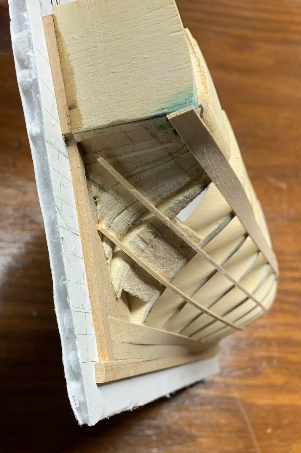
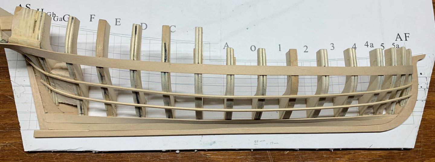
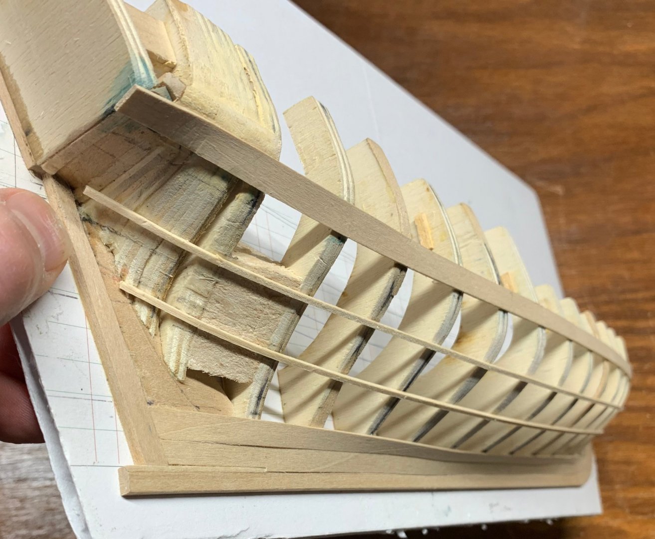
It's been almost nine months since I posted anything to this build log. Frankly, I was so frustrated with this project that I put it aside. I've since finished another model and decided to take another look at the half hull project. It hasn't gotten better with age. Just look at this thing... This was my second attempt! And it wasn't like it was just the wale that needed work. The object here is to create a "pleasing run of planking." I hadn't created that. I'd created a chaotic mess. Kinks that I doubted I could work out around the bow. Uneven plank widths in the stern. Wavy lines. I was really discouraged and just didn't want to put more work into something that was clearly not going turn into something of which I might be proud. So I trashed it. Well, not completely. I just removed all the planking. I'd used white glue, so a little water softened up the joints. Then I removed any excess glue with a damp cloth. Then I started fairing the hull again, being even more meticulous about the bow and stern. I found that I'd sanded a little too much off the aft frames. The instructions say not to do this and I tried to follow them, but I couldn't figure it out. Turns out, the stern is a lot more boxy than I thought it was. Coming to that conclusion showed me where my errors were and I corrected them. The forward-most frame was a little too short, so I extended it. I removed the spacers so I could properly mark the wales without going through all kinds of gyrations with my square. I copied a technique shown in one of the other build logs where the measurements are punched into the frames. One of the problems I had was with smudged pencil marks, particularly in the bow. This technique solves the problem. I added a little more filler in the stern to give a better gluing surface for the stealer. I'd run out of planking material building what I'd already built, so I went off to Hobby Lobby to get more 1/32" planking material. I also re-read Planking the Built-Up Ship Model. I think, for this re-build, I'm going to use some of the techniques described in that book, particularly with regard to laying out the planking. I have a pair of proportional dividers, not the expensive ones used by draftsmen of old, but inexpensive ones uses by artists, with set proportions. I think that's going to make laying out the runs of planks easier and more accurate. So I'm back in the saddle again, as the old cowboy song says. The frame is fair. The wale is installed. Off once again to the garboard strake. Dan
-
How do you remove underbleed like that? I've messed this up so many times, I find ways to avoid situation where it might happen. Dan
-
Thanks, everyone! Nic, I will definitely be taking you up on your offer. I just have to figure out what kit I want to build. That's a tough choice. Like Kurt said, the model did win a Gold Award in the Wisconsin Maritime Museum Annual Model Ships and Boats Contest, which was really a thrill. I thoroughly enjoyed building this model and did it to 1) relieve my COVID fatigue and 2) learn how to make proper sails. Mission Accomplished, I think, on those two points. I appreciate the comments about the sawhorses. Necessity is the mother of invention and I thought a good long time about how to best display the model. Glad you liked the result. Dan
- 24 replies
-
- 3
-

-
- Bluejacket Shipcrafters
- Finished
- (and 1 more)
-
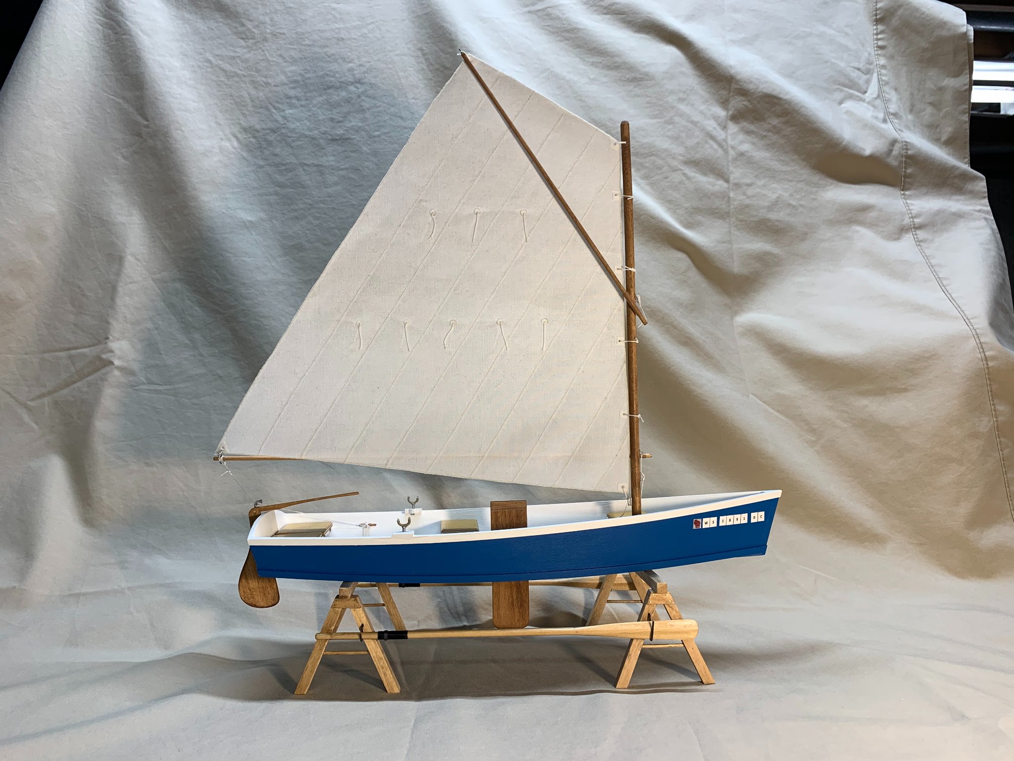
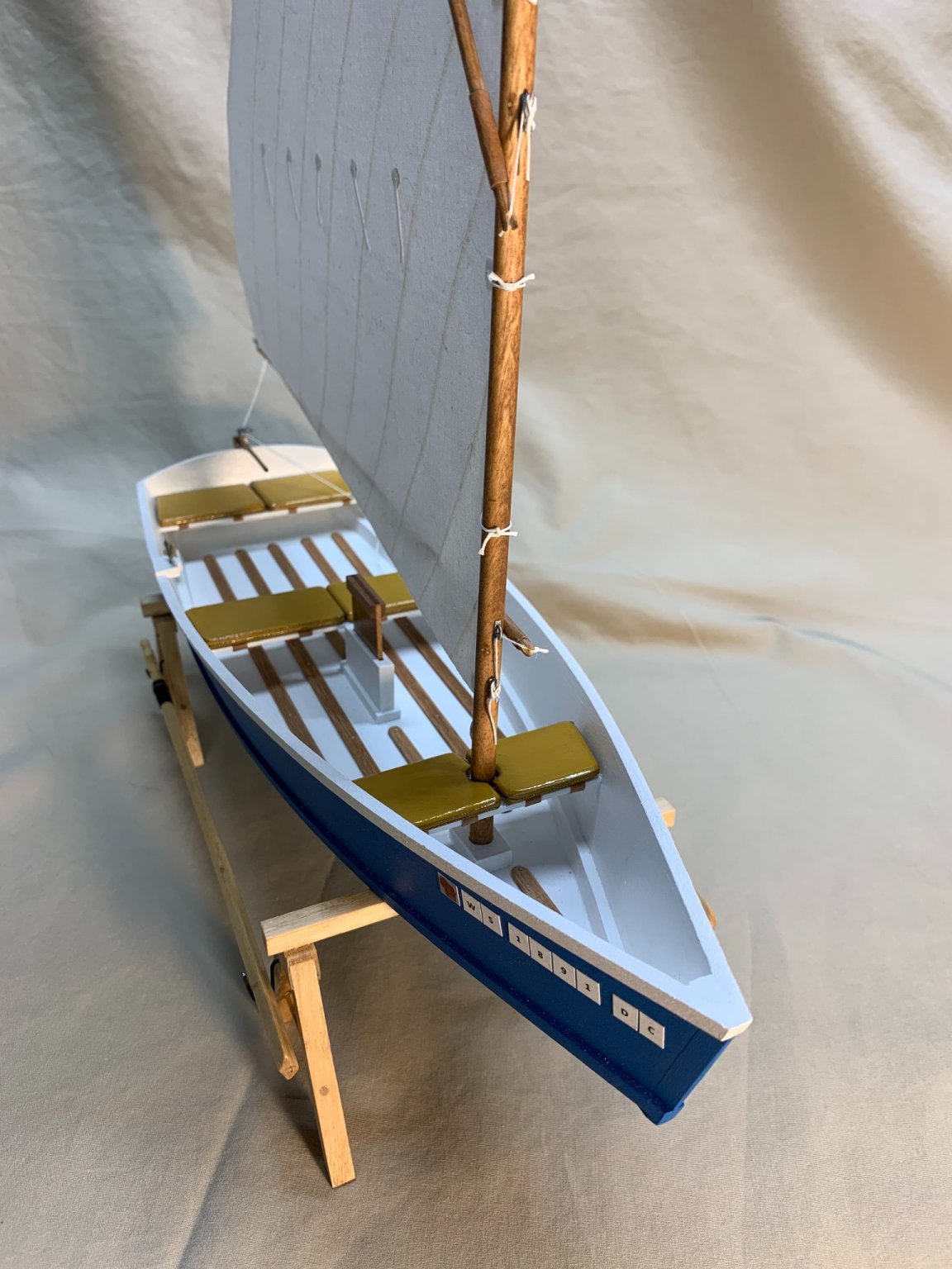
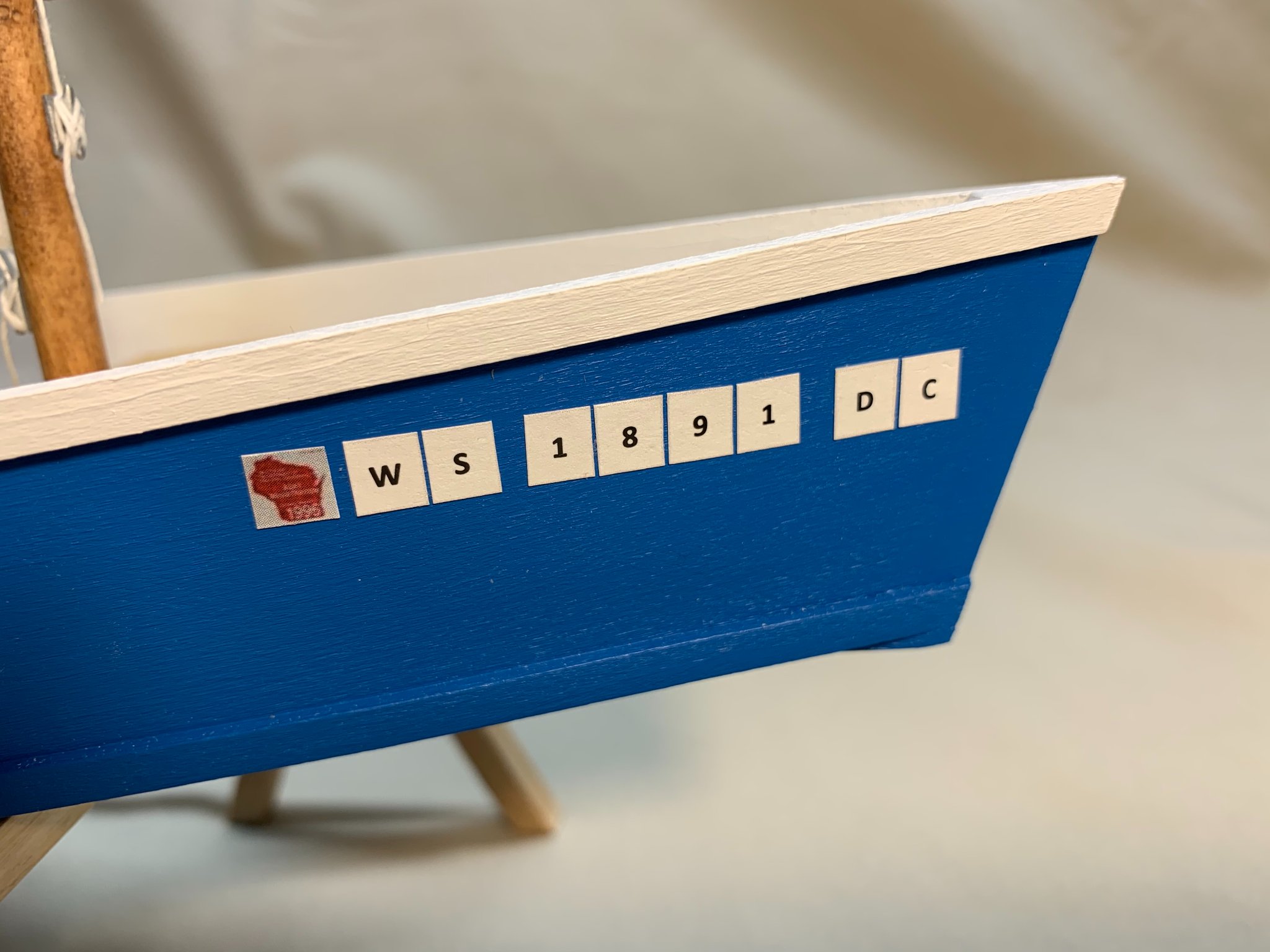
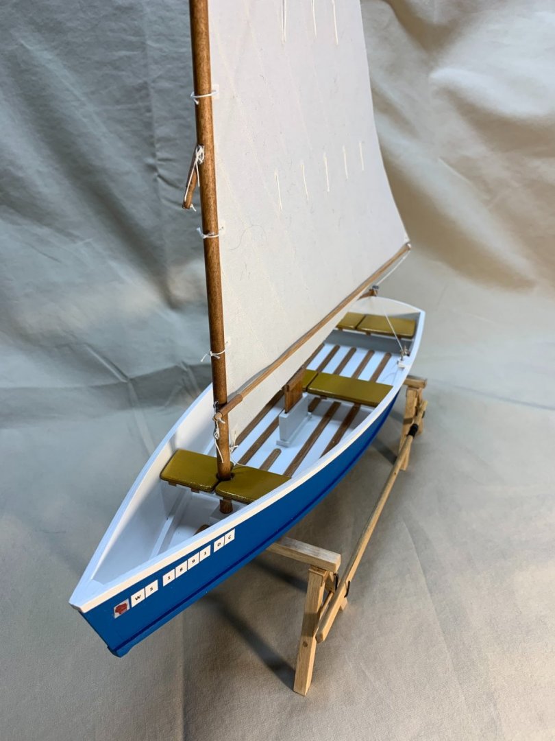
To finish the model off, I decided I needed I needed a boat license. The current Wisconsin boat license stickers are dark blue, so they would have blended in too much with the color of the boat. (I live in Illinois but grew up in Wisconsin. I just can’t get it out of my system.) For no particular reason, I looked on eBay for a Wisconsin boat license and, sure enough, someone was selling a 1996 sticker. I snagged the image, scaled it to the proper size (3”) and, along with some random numbers and my initials, I applied them to the hull. This license complies with the Wisconsin DNR’s rules! The final details are the drain plugs. Everyone knows, after a long day on the lake, you’ve got the drain the water out of the boat. I used my small punch and die set to punch out some small diameter (1” in scale) disks that I glued together with CA and then tapped a little depression in to simulate the socket for the wrench to pull out the drain plug. I’ve very happy with how this model turned out. The kit itself went together wonderfully and it offers lots of opportunities to improve, scratchbuild and make unique. Just yesterday, we learned that we can take our masks off (with some caveats) which is a much better way to cure COVID fatigue, but, in a pinch, I’d recommend this kit. I’ve entered the model in the 2021 Wisconsin Maritime Museum Model Boat Show and Contest. The contest is virtual this year. Judging is, as I understand it, completed, but I won’t know until tomorrow night how I did. Here are some pictures of the finished model.

- 24 replies
-
- 3
-
-
- Bluejacket Shipcrafters
- Finished
- (and 1 more)
-
I struggled a little bit deciding how I was going to mount and display the model. I toyed with the idea of putting the boat on a beach like Steve Wheeler had done, but that would make for a bigger footprint than I wanted. I didn’t like the simple stand that came with the kit. I didn’t want a very formal mounting like brass pedestals. I finally decided on sawhorses. I needed something that would allow the rudder to hang down below the bottom of the boat and something that would allow me to display the oars. (I’d thought about just putting the oars in the boat, but I thought they obscured too much detail and looked like they didn’t belong there. I used my own sawhorses as models, taking measurements from them. I used basswood stock for construction and brass wire to simulate fasteners. I used some anodized brass wire to fashion some hooks upon which to display the oars. I painted the model using Artist Loft acrylic paints from Michael’s. As this model was a cure for COVID fatigue, I was looking for inexpensive, forgiving, simple materials everywhere possible. My son, who is still taking art lessons, had some of these paints, but he grew frustrated with me “borrowing” them to use on my model, so I needed to go buy my own!
- 24 replies
-
- 1
-
-
- Bluejacket Shipcrafters
- Finished
- (and 1 more)
-
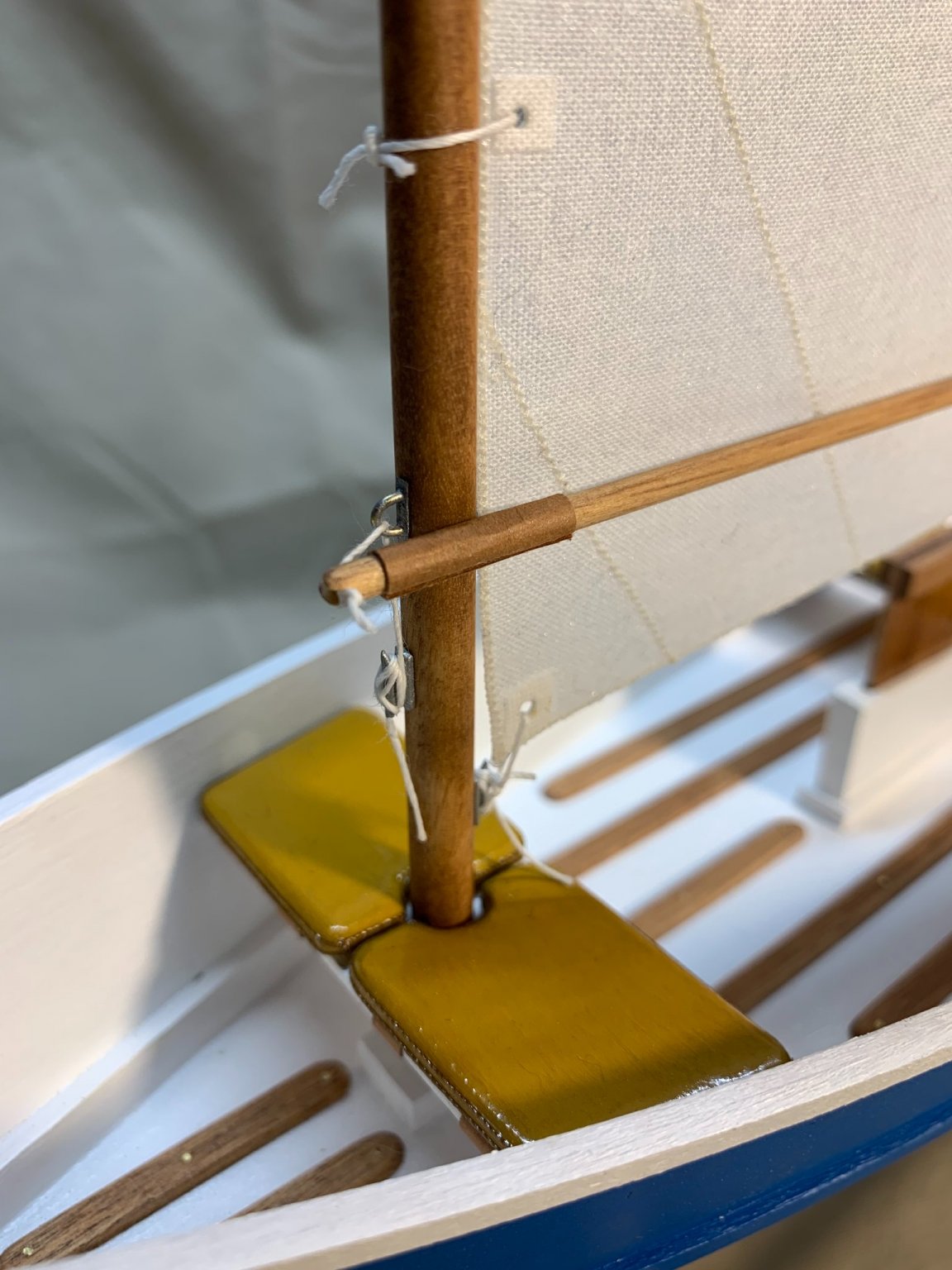
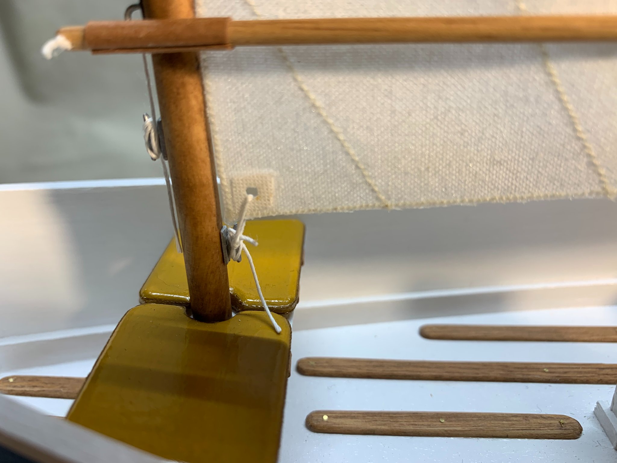
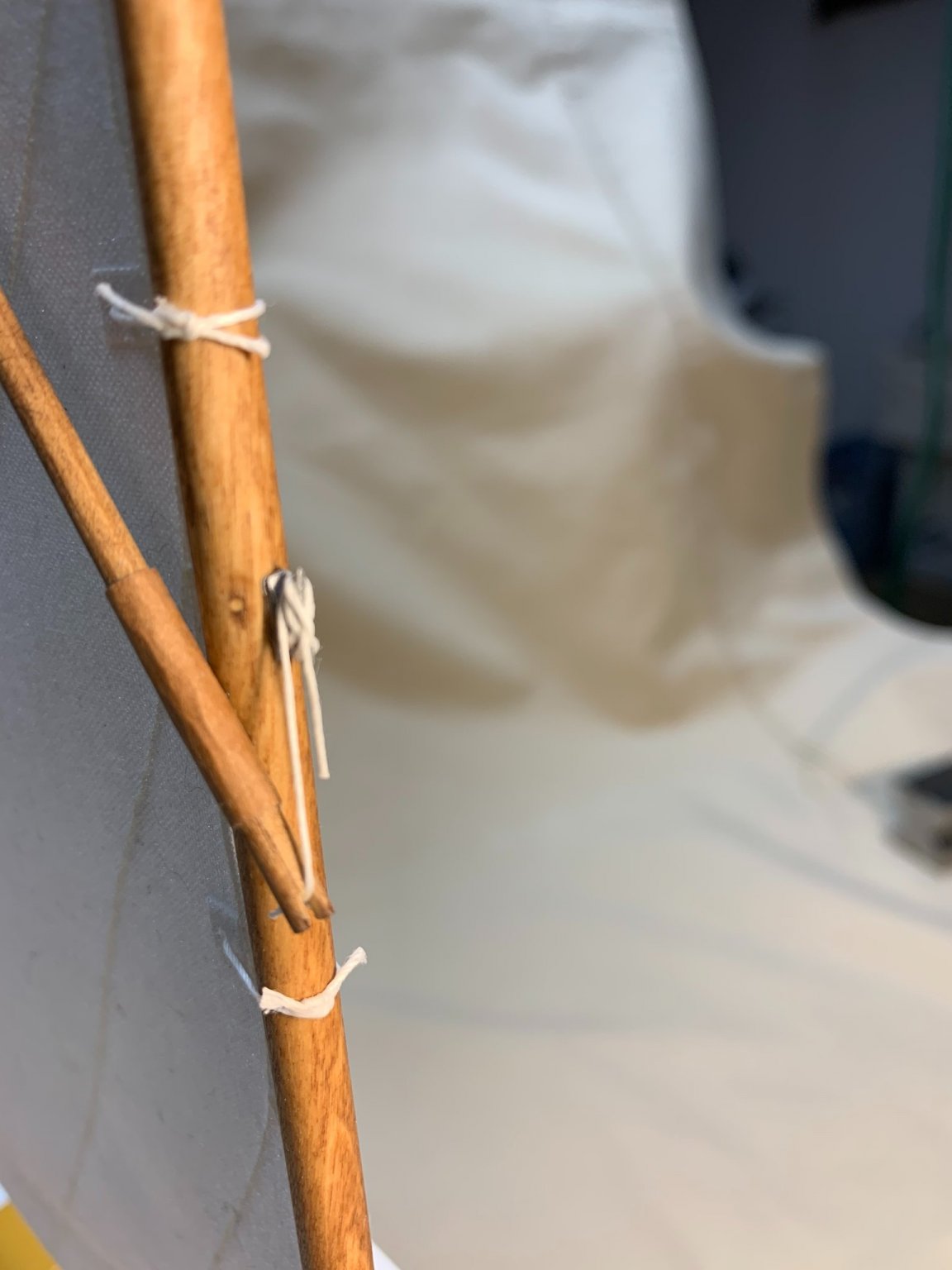
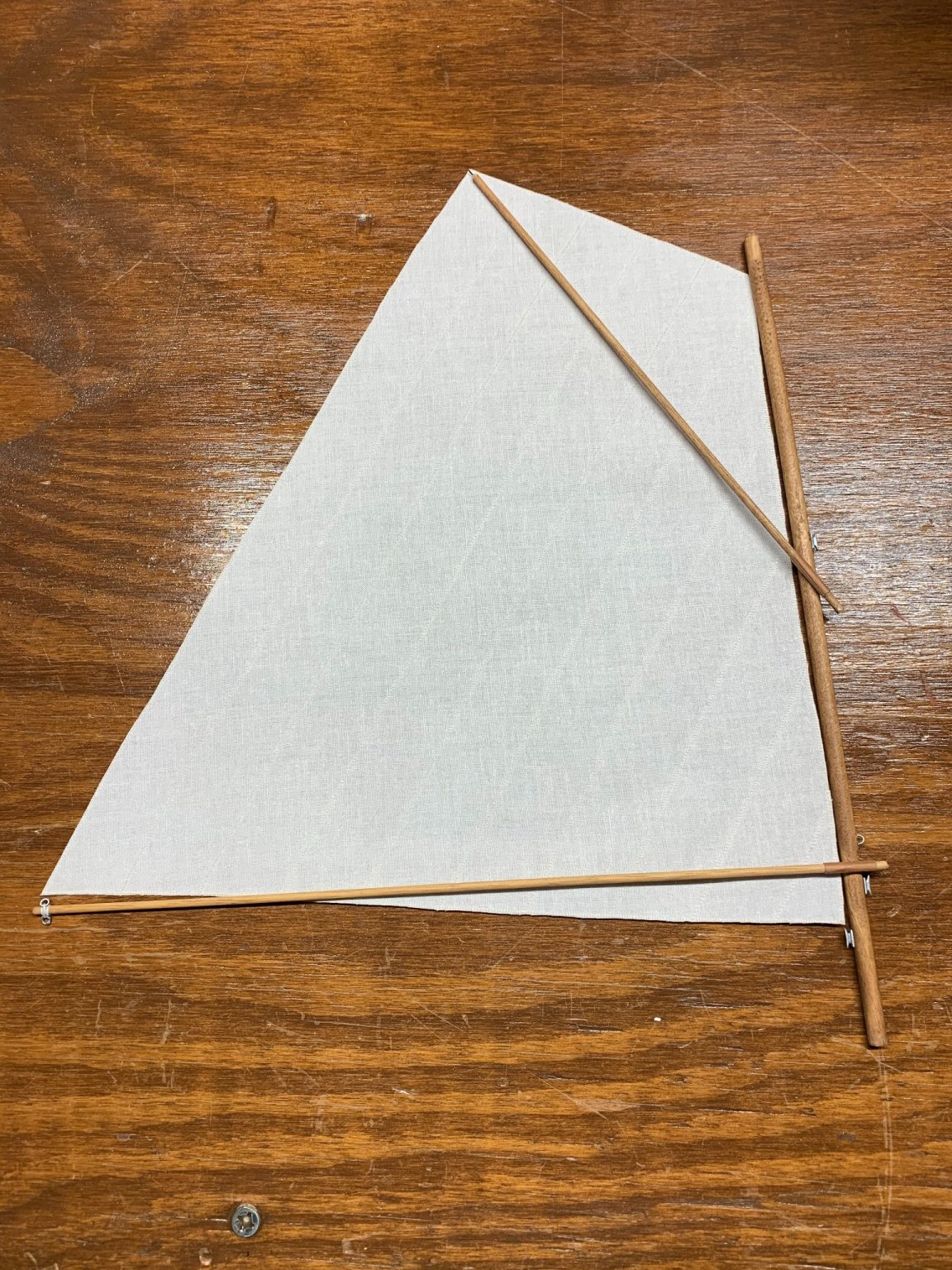
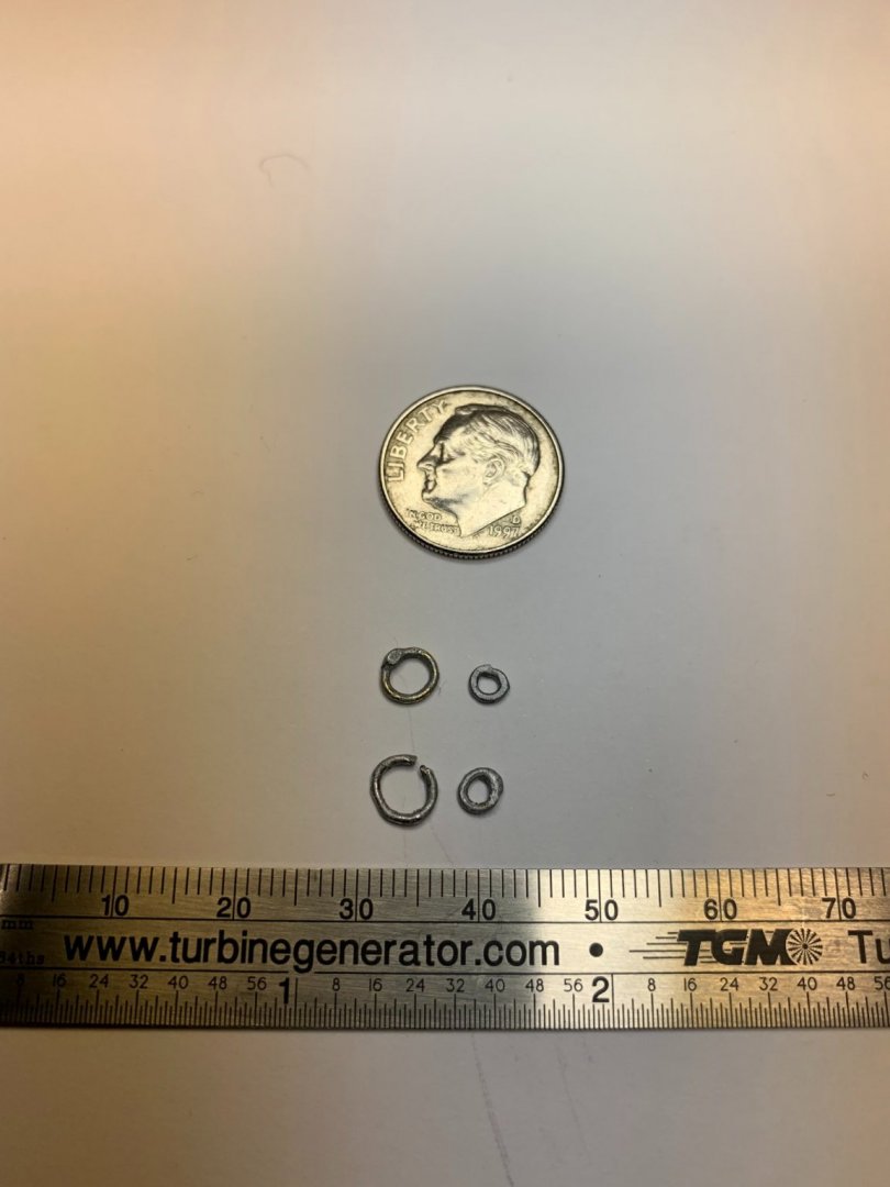
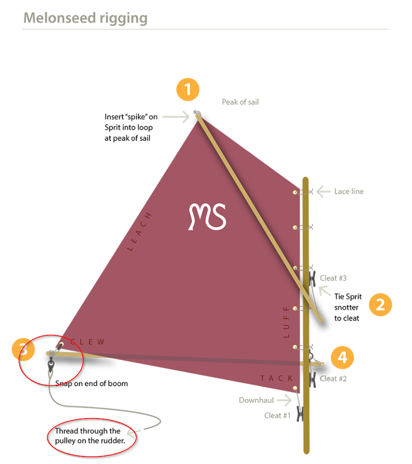
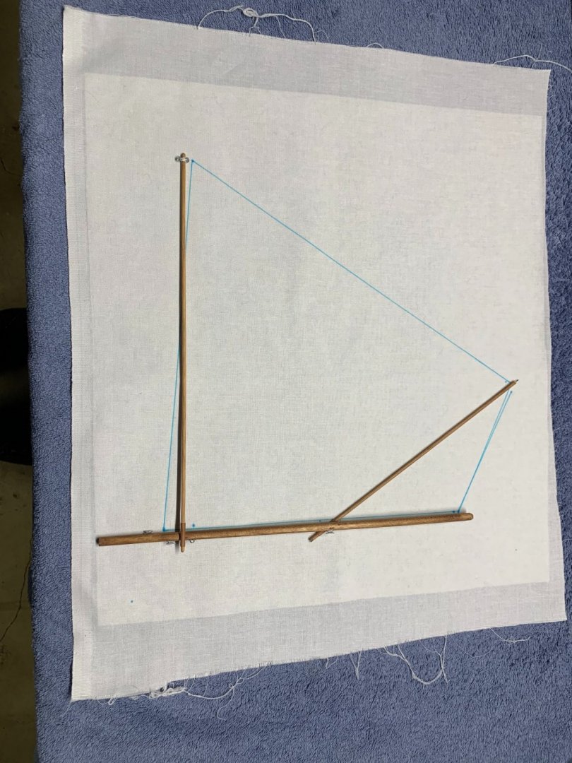
You can see the assembled rig in the picture. Mounting it in the boat was simple. The only other things needed were a single block — thanks, again, Bluejacket! — and a rope coil for the sheet line on the deck. I also made sure that all the knots used were accurate. The sheet line is attached to the ring with a bowline run through a ring. The downhaul, sprit and boom halyards are all secured to the cleats properly. For the boom, sprit and mast, I scaled the measurements shown in the melonseed rig drawing. I obtained most of the various fittings from Bluejacket Shipcrafters. They didn’t have the loop shown on the lower mast, so I made that from brass stock and wire. All the fittings were painted with Model Master aluminum. The leather wraps were made from scrapbooking paper. For the rings on the end of the boom — for attaching the clew of the sail and the sheet line — I used brass wire soldered into rings. It took a little trial and error to get to the smallest diameter I could manage. In the end, I got down to about 2 mm.
- 24 replies
-
- 1
-
-
- Bluejacket Shipcrafters
- Finished
- (and 1 more)
-
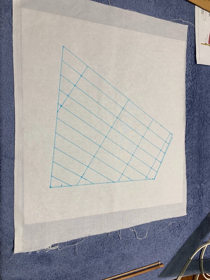
I used embroidery stabilizer to stiffen the sail material. Then I used a water-soluble fabric marking pen to mark out the outline of the sail itself. To add realism to it, I decided to sew panel lines into the sail. Since the model is in 1:12 scale and panels were typically 1 foot wide, the seams would be 1 inch apart on the model sail. I used a ruler/straightedge, triangle and dividers to lay out those lines. I used a sewing machine set for the finest stitch it could produce. I also used the finest needle I had available and a fine thread a little darker than the sail material, just to give it some contrast. Sewing the sail was much easier than I thought it would be and went quite quickly. As I worked along, I decided the sail needed some additional details. The attachment points, I thought, needed some reinforcement, so I made some grommets from leftover sail material and used my punch and die set to see if I could punch some clean holes through the sail to simulate those attachment points. I also made some grommets for telltales and attached them to the sail. A lot of the reading I’ve done indicated that people don’t use telltales on a melonseed, but I’ve never sailed a boat that didn’t have them, so I decided to include them. They certainly make the sail more interesting to look at. Punching those holes in the sail required a very stiff sail. That was achieved by spraying the sail with clear gloss automotive lacquer. It gives the sail a lot of body and a great appearance.

- 24 replies
-
- 3
-
-
- Bluejacket Shipcrafters
- Finished
- (and 1 more)
-
I really deviated from the kit with the rig. The kit-supplied rig is pure simplicity. It’s just a mast, a sprit and a plastic sail. I wanted to do a little more with that. One of the prettiest rigs I’ve seen is the one on a melonseed skiff. It’s got several names, but it’s got a sprit — like the kit-supplied rig — and a boom. The sheet line runs through a block attached to the tiller head. As far as sailboat rigs go, it’s very simple, but I thought it would look great on this model. I haven’t put sails on a model since I was a kid. I’ve found they obscure detail and often look out of scale. But a modeler I respect a great deal, Steve Wheeler, built boat models in this scale and routinely put great-looking sails on them. I decided to give it a try with the skiff and used Steve’s April 2004 article “Making Sails” in Ships in Scale magazine as a guide. I obtained almost everything I needed from Hobby Lobby. I started with some 270 thread count white bedsheet material. Steve recommended washing, drying and starching it before working with it. Then I made a paper pattern to ensure the final product would fit on the model.
- 24 replies
-
- 2
-
-
- Bluejacket Shipcrafters
- Finished
- (and 1 more)
-
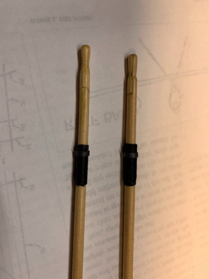
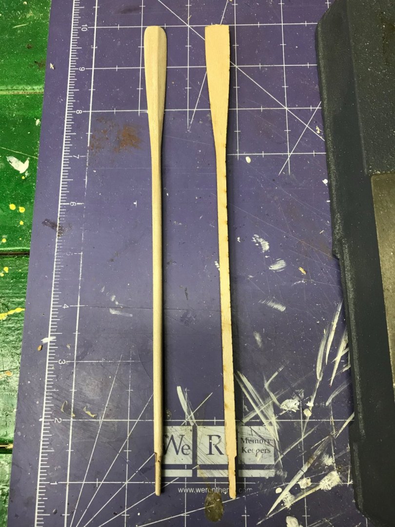
After turning the oars, I finished the blades, putting the proper bevel on them. They were finished with polyurethane. Any good oar has oar wraps, so I used some black rigging thread of an appropriate-looking diameter and wrapped them. I used some back scrapbooking paper to simulate the rubber “button” that keeps the oars from sliding out of the oarlocks. The wrapping was secured with a little thinned white glue.
- 24 replies
-
- 2
-
-

-
- Bluejacket Shipcrafters
- Finished
- (and 1 more)
-
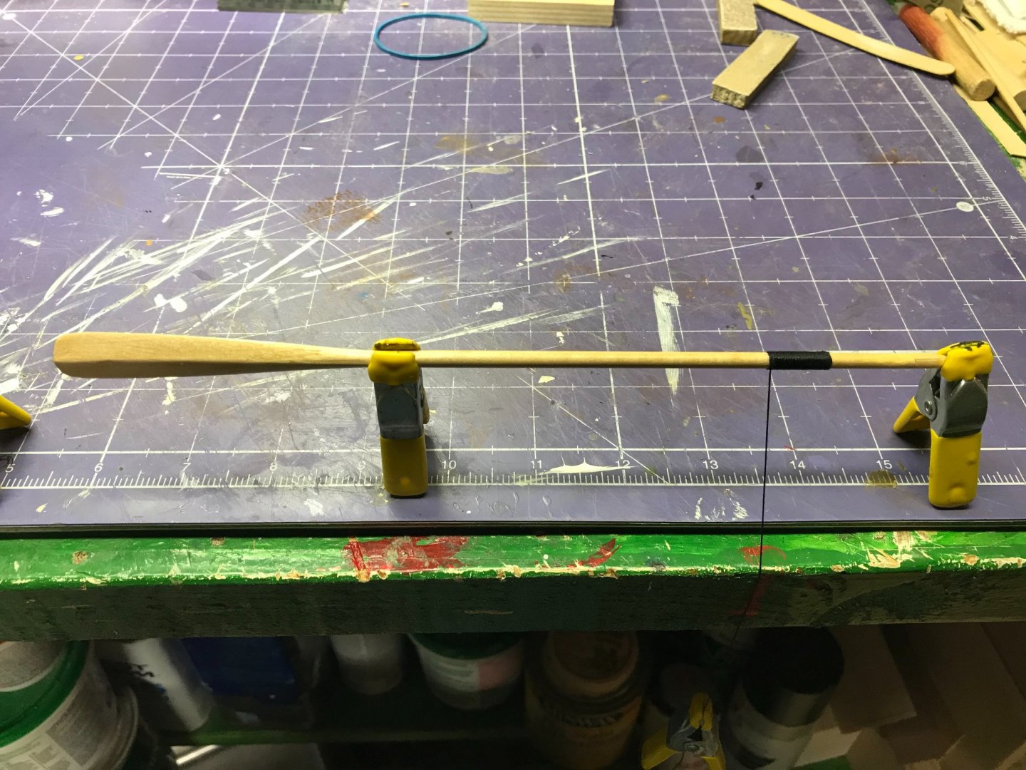
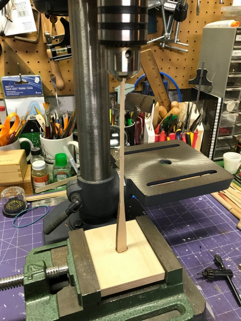
To make the oars, I used a technique I learned from my friend Bob Filipowski. He turns oars and other cylindrical parts like masts and yards in a drill press. I started out turning these parts in a lathe, but I found that, because of the small diameter of these parts and their tendency to flex in the lathe when worked, they became oval in cross section. That doesn’t happen in a drill press. I used Bob’s technique exclusively now. I chucked the blanks in the drill press and held the other end in a block of scrap wood with a hole of the proper diameter drilled in it. This keeps the “loose” end of the oar from flying away and breaking.
- 24 replies
-
- 3
-
-
- Bluejacket Shipcrafters
- Finished
- (and 1 more)
-
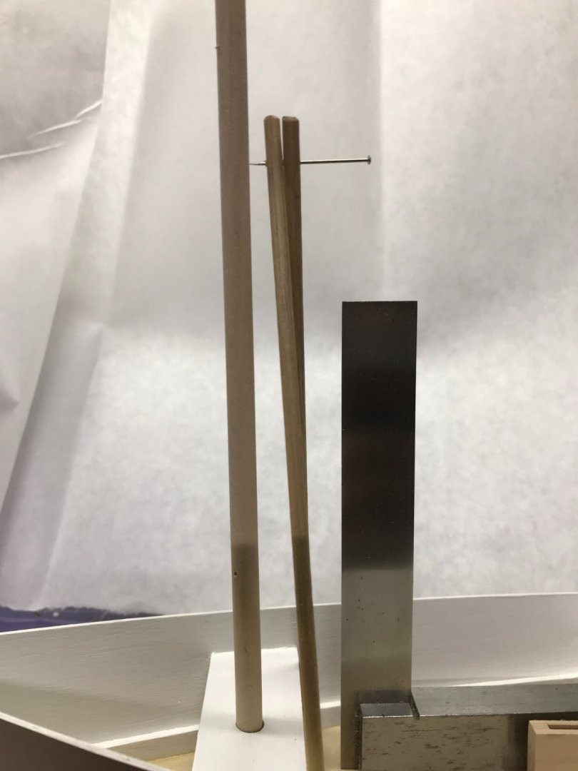
Stepping the mast came next. To align the mast, I used a tool I made for that purpose many years ago. It’s simple enough: two small dowels of equal length with a pin driven through both. Place the two “legs” against the bulwarks and the pin should be in the center of the mast. (This is another reason to make sure the chines are equidistant from the centerline.) When the pin is in the center of the mast, it’s aligned laterally. To ensure it’s vertical, I used a small machinists square.
- 24 replies
-
- 2
-
-
- Bluejacket Shipcrafters
- Finished
- (and 1 more)
-
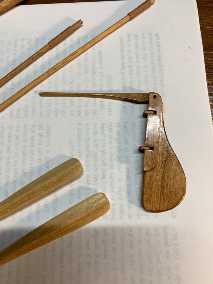
The rudder, as the instructions explain, is a model in itself. It’s made from nine parts. As with the daggerboard, I wanted a natural finish, so I sanded the parts, stained them and varnished them with the polyurethane. I found I needed to knock some of the gloss off this assembly to make it look more realistic.
- 24 replies
-
- 2
-
-
- Bluejacket Shipcrafters
- Finished
- (and 1 more)
-
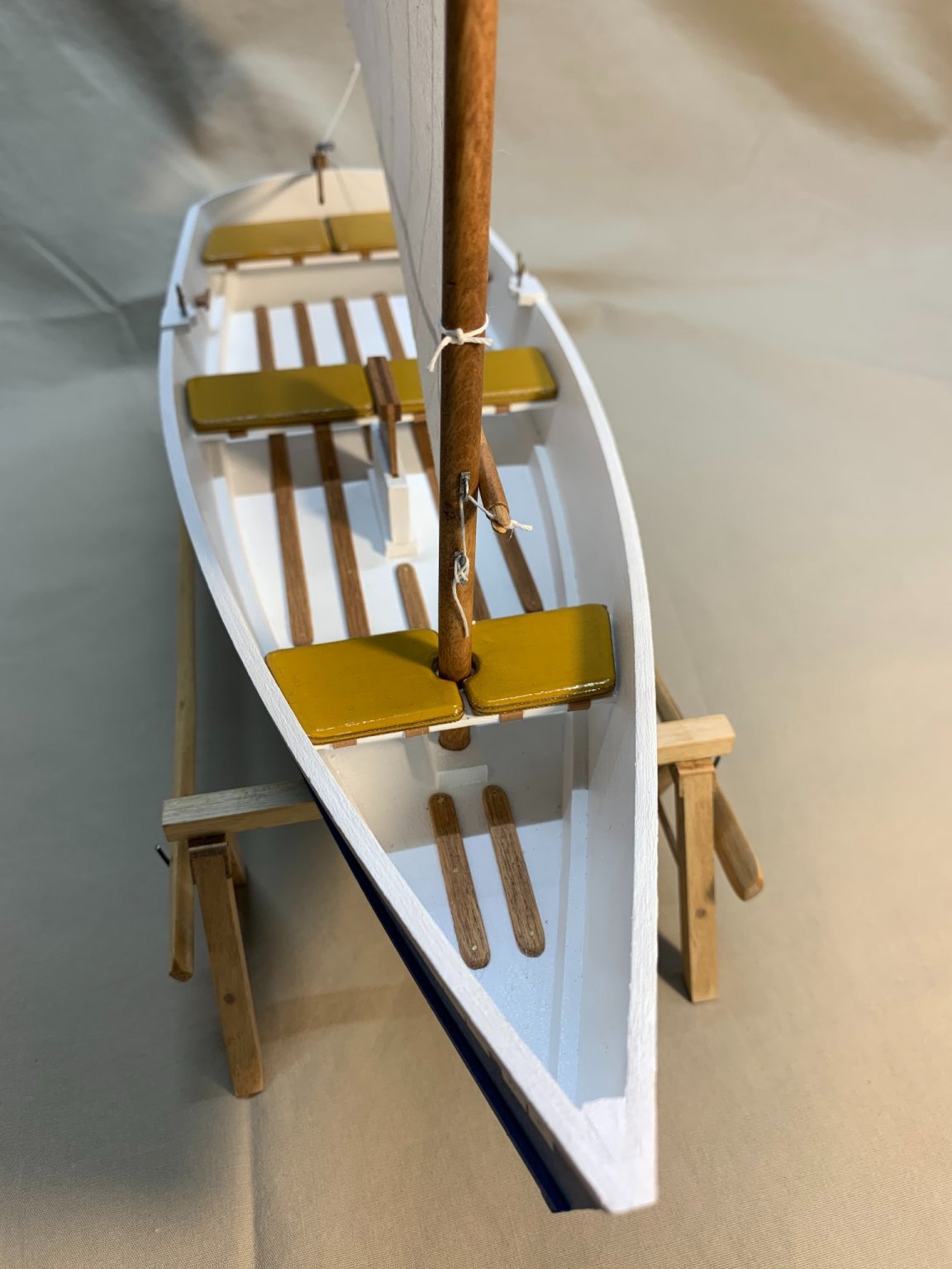
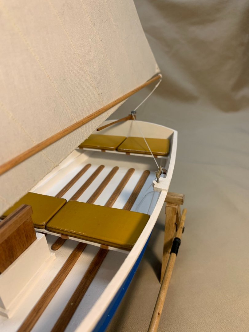
Also at this time, I made some seat cushions. There are no seat cushions in the kit, so using the frames from which the parts were removed, I created some from basswood. I decided there would be two cushions on each seat. I beveled the edges all around and used some appropriately-sized and colored thread to simulate the binding common on all these kinds of cushions. I painted them and sealed them with polyurethane. I then used scrapbooking paper — heavy bond paper that comes in many different textures and colors — to simulate the straps that would hold these kinds of cushions in place on a real boat.
- 24 replies
-
- 2
-
-
-
- Bluejacket Shipcrafters
- Finished
- (and 1 more)
-
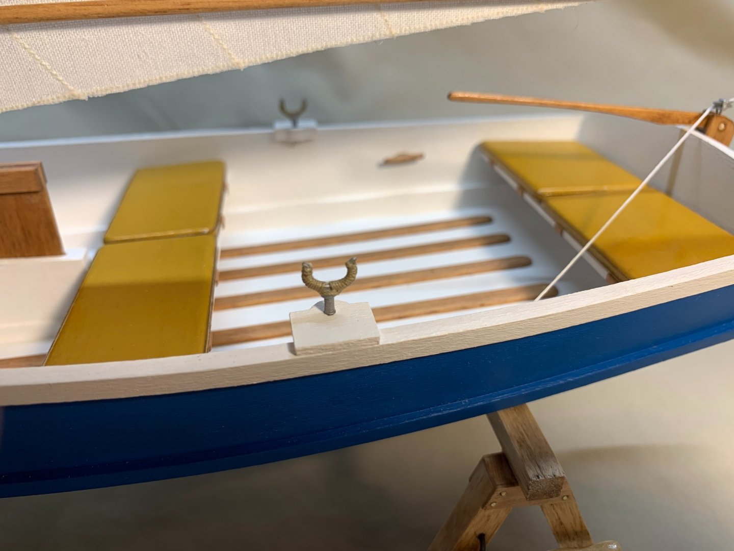
The oarlock blocks are simple enough to install. They’re just blocks of wood with holes in them, but I wanted to dress up the oarlocks themselves. After dressing them up with a file, I painted them with Model Master acrylic aluminum paint (1781) and wrapped them with a manila-colored thread. These wraps reduce the wear on the oars in a real boat. I didn’t take pictures of these features at the time, so I’m going to jump around a little. You might notice the floorboards I installed. On a real boat, when these aren’t installed, your feet always get wet, along with anything else thrown in the bottom of the boat! I used some mahogany strips I had in my model wood pile. I cut them out, beveled the edges and rounded the end. I stained them with MINWAX stain. I laid them out in what looked to me to be a logical pattern on the bottom of the boat. I drilled small holes in the floorboards and used light gauge brass wire to simulate the screws used to hold them in place.
- 24 replies
-
- 2
-
-

-
- Bluejacket Shipcrafters
- Finished
- (and 1 more)
-
The daggerboard trunk is a four-piece box that needs to be aligned in the hole in the bottom of the boat. I used some small squares and a clamp to ensure proper alignment. The daggerboard is a simple assembly. I sanded it into the proper shape with a sharper edge on the trailing edge and rounded the leading edge. I intended to paint the boat, but to leave some of the fittings in a natural wood finish. I stained the daggerboard with MINWAX cherry stain and a light coat of MINWAX satin polyurethane. You can see in the photo at the right the daggerboard trunk with the trim pieces installed.
- 24 replies
-
- 2
-
-
-
- Bluejacket Shipcrafters
- Finished
- (and 1 more)
-
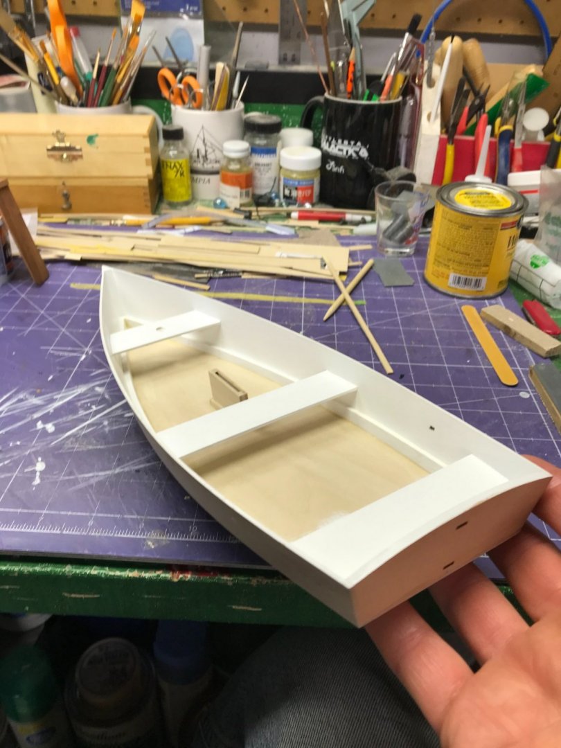
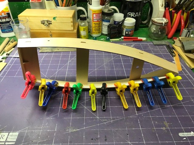
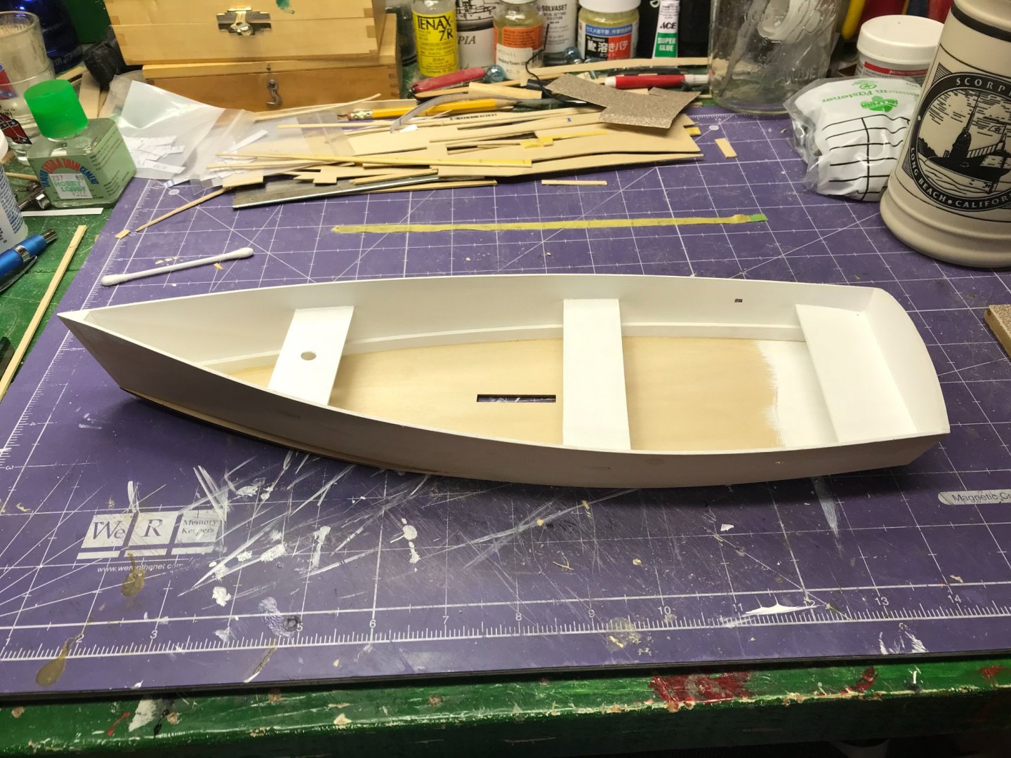
The next steps are to glue in the transom seat, sand the outer edges of the transom and the transom seat to match each other and then line up the aft edge of the hull sides with the aft edge of the assembled transom and glue everything together. This is probably a good place to note that I sanded every piece before I install it, just to make sure I don’t get into a position where I can’t reach something later in the construction. I used 120, 180 and 600 grits. Next, the stem piece is installed (a triangular piece that provides a gluing surface for the sides). The midships and forward seats are glued to one side and then the two sides of the hull are brought together and glued. Then the chines are fitted inside the hull. This is the first slightly challenging operation. The chines are made from relatively thick stock and do not bend easily. I recommend wetting the chines, fitting them inside the hull and clamping them as shown in the photo. Wetting the chines makes them more flexible and will put less stress on the hull structure when installed. Installing the hull bottom is simple enough, but a little time needs to be spent ensuring proper alignment. The bottom is large enough to have overhang all the way around the hull, but the chines can distort the hull shape, so spend some time ensuring the hull is straight and true. Use the centerboard trunk as a reference and make sure the distance from the centerboard trunk to the chines are equal on both sides. One other thing: once the bottom is installed, painting the bottom of the seats or the area aft under the aft seat will be impossible. I painted those areas before installing the bottom. The model, of course, doesn’t fit together like a jigsaw puzzle. There will be gaps between the parts, in the slots where the tabs are fitted and around the edges of the after seat and transom. I used Elmer’s Wood Filler, thinned with a little water, to fill all those gaps.
- 24 replies
-
- 3
-
-
- Bluejacket Shipcrafters
- Finished
- (and 1 more)
-
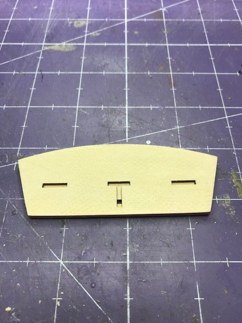
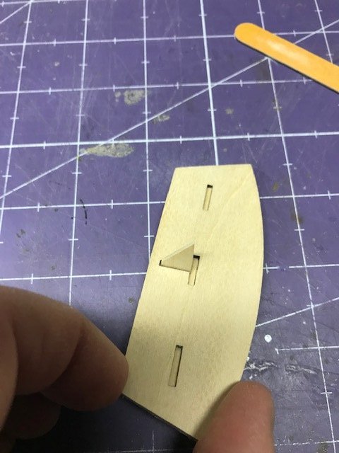
The pieces are removed from the basswood sheet with a hobby knife. I used white glue for everything in this project. It’s inexpensive, easy to obtain, cleans up with water and dries quickly. I usually use a little piece of plate glass to mix paints, adhesives and as a stable, flat surface on which to align things. I always apply glue with a small paint brush to control how much I apply. I use small plastic clamps from Harbor Freight Tools for a lot of tasks like this. They’re very inexpensive, come in packs of six and don’t create a lot of pressure that can distort delicate parts. The transom seat knee is the first part that requires a little modification. The slot is wider than the knee, so it needs to be shimmed. I used a business card for this, but any piece of paper will work, just enough so the part fits in the slot and can be oriented perpendicular to the transom. Without an inspection mirror, it’s impossible to see that transom seat knee on the finished model, so some people might wonder why anyone would even bother shimming it and making it exactly perpendicular. It’s just me. I build for myself. If I didn’t do the job properly, every time I looked at the model, I’d see those defects.
- 24 replies
-
- 2
-
-
- Bluejacket Shipcrafters
- Finished
- (and 1 more)
-
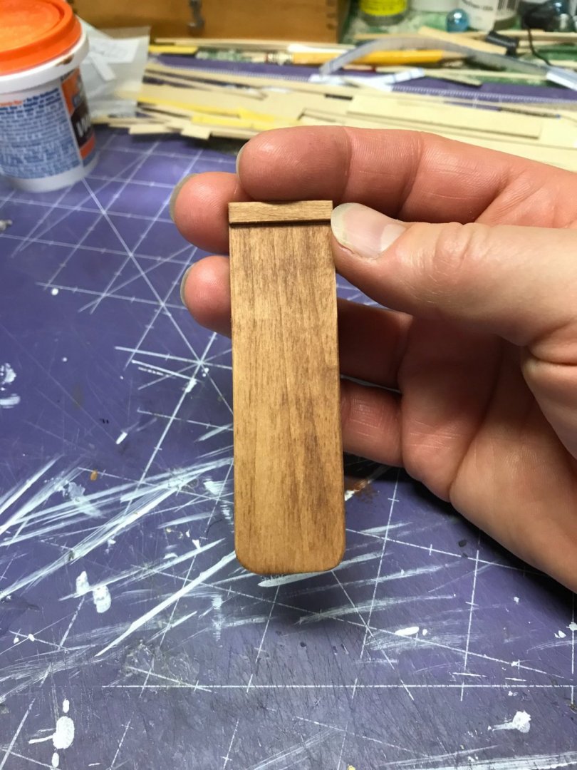
The skiff is the simplest of Bluejacket’s kits. It’s a typical flat-bottomed boat in 1:12 scale (1” = 1’). I visited Bluejacket Shipcrafters on vacation several years ago and Nic said about the kit, “you can build that in about three hours.” I suppose you could slap it together in that amount of time; it took me a little longer. His point was correct, though. This kit was designed for the first-time builder, regardless of age. It requires simple tools and basic construction techniques. The instructions and plans are clear and complete. If that was your goal, you really could assemble the model in three hours. Still thinking the kids might want to build this model someday — I still have two more in my stash! — I took a lot of pictures of the early construction details and made notes of things that might not be obvious to them. Some of those photos and notes helped me with this build log. First, glue together the outer and inner transom and then glue the transom seat knee into the vertical slot in the inner transom.


- 24 replies
-
- 3
-
-
- Bluejacket Shipcrafters
- Finished
- (and 1 more)
-
In 2018, I bought three Bluejacket Skiff kits. The kids’ art teacher had suggested I might teach a model boat building class for her students. Nothing ever came of that and the kits went into my stash. I was feeling some COVID fatigue a few months ago and, wanting to work on something that wasn’t going to take a great deal of mental energy the skiff came out of the stash and onto the workbench. Here’s the finished model.
- 24 replies
-
- 3
-
-
- Bluejacket Shipcrafters
- Finished
- (and 1 more)
-
Thanks, everyone! I'll try these methods out and see what happens! Dan
- 8 replies
-
- 1
-
-
- small boat
- sails
- (and 1 more)