HOLIDAY DONATION DRIVE - SUPPORT MSW - DO YOUR PART TO KEEP THIS GREAT FORUM GOING! (Only 24 donations so far out of 49,000 members - C'mon guys!)
×


dcicero
-
Posts
267 -
Joined
-
Last visited
Content Type
Profiles
Forums
Gallery
Events
Everything posted by dcicero
-
Save, yes, but re-use? I doubt it. They're so far off that making new ones is going to be the only solution. I can save the wood for something else, maybe, but that's about it. Cost of learning... Dan
-
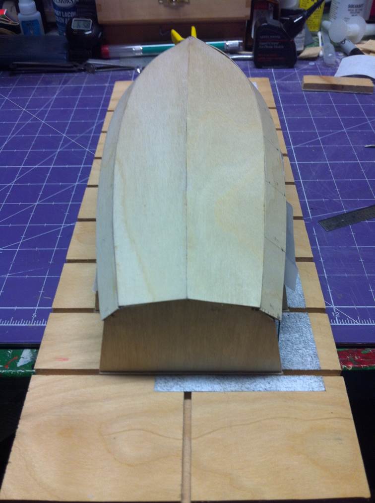
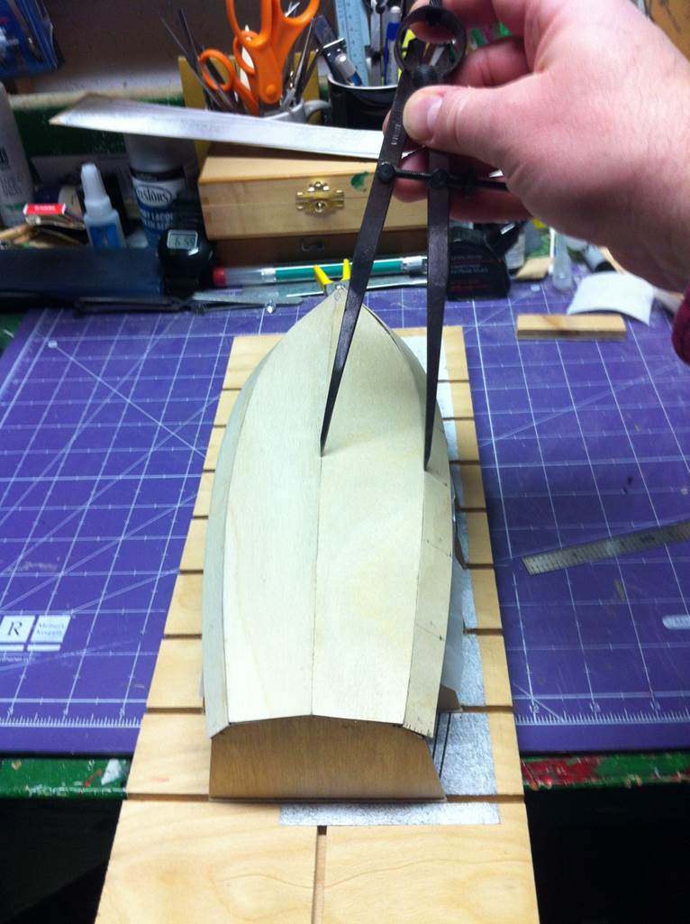
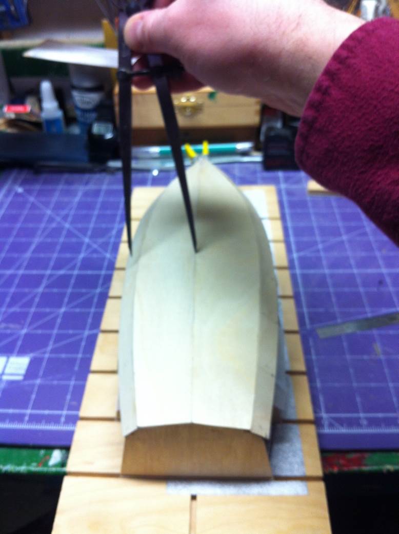
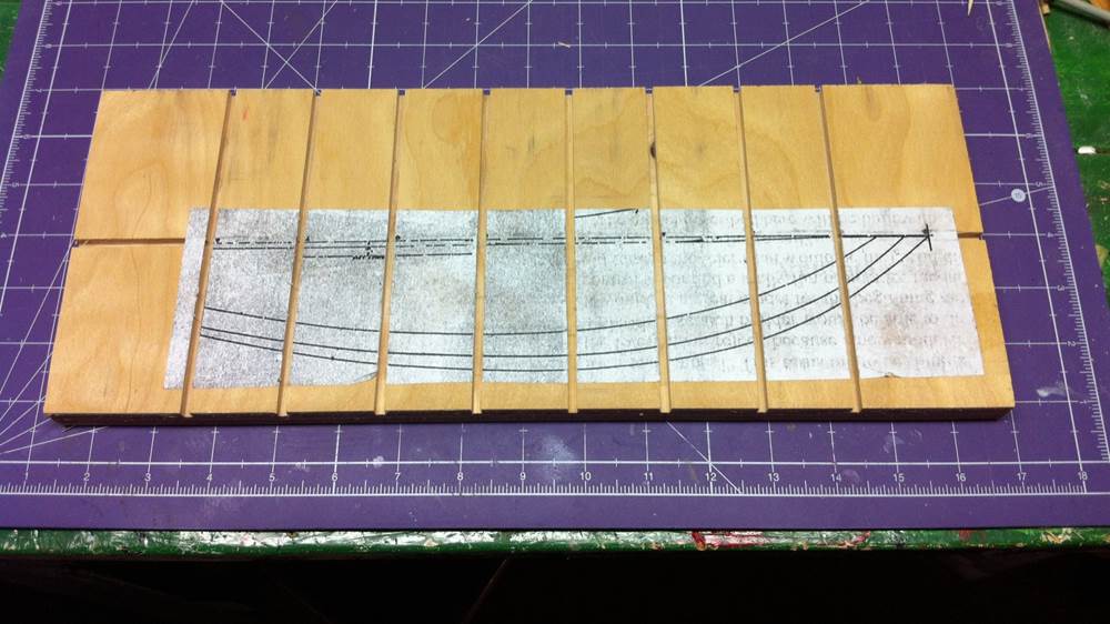
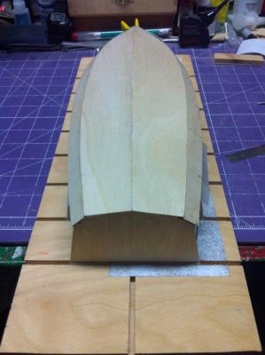
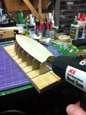
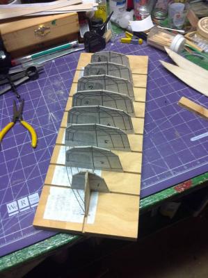
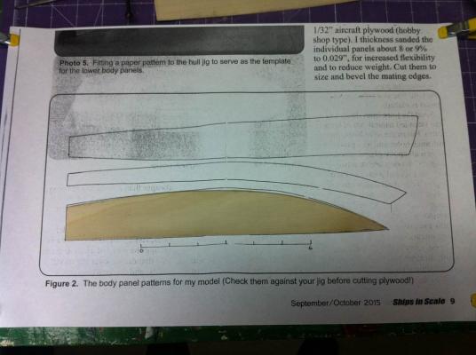
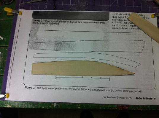
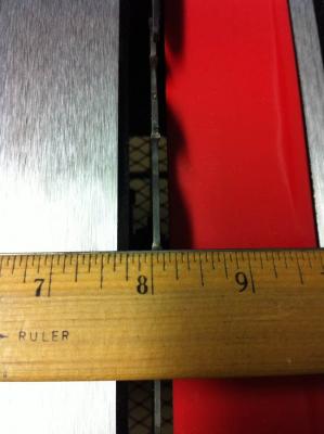
It's been a while since I posted anything here on Model Ship World. (Real life's been in the way!) I've made some progress on my footy, but a lot of the progress has been in reverse. The building of the jig/building board went very well and I was pleased with the results. I cut the templates out for the hull and laid them on the jig, but wasn't very happy with how they looked. They're roughly drawn, as you can see in the pictures, so I decided to do them from scratch, marking out the dimensions on a piece of paper and then transferring that to the plywood and cutting them out. I got the first two sections installed that way and here's the result. Looks good, right? But it's not. It's not straight. I measured the hull at Frame 5 with a pair of dividers. And then did the same thing on the other side of the boat. Although the picture is a little fuzzy, you can see that the measurement is way off. I pondered this for a while. Getting those planks on was a pain. I didn't have enough plywood to do it again, so I'd have to run over to Menard's and get some more. I tried to figure out a way to make it work out, but, finally, I paid attention to the advice I got from Ken Quast: it's always faster to make something again than fix something that didn't work out the first time. I decided to take a few steps back. A little internet searching revealed that the Titebond III that I'd used to attach the hull sections could be loosened with heat, so I pulled my trusty heat gun out of the toolbox and went to work. I was expecting a battle. Titebond III is a very strong adhesive and I was worried that I would need to apply so much heat that I'd do damage to my jig. Not to worry. The planks came off easily and very little heat was necessary, certainly a lot less than my heat gun was capable of delivering. So, although I'm not back to Square 1, I'm probably back to Square 3 or 4. I dropped the removed planks on the template to see how far they were off. (After cutting them, I needed to sand them to final form and the template itself was removed from the plywood, so there was no way to gauge any of this on the model.) They're certainly not the same as the template and they're not the same as each other. And that's why the whole thing didn't work out. The pictures don't really do justice to the difference between these sections. They're not close at all. So... This time, I think I'm going to sandwich the two pieces of plywood together, attach the template to the top and go from there. That'll at least give me two, identical sections. They may not fit properly on the jig -- which will mean I have to adjust some -- but I should get closer than I got the last time. Live and learn. I'm back in a forward gear now. Dan


-
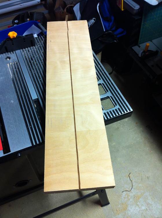
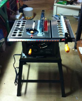
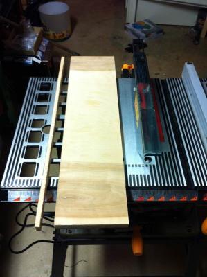
Time for an update. Like others have said, you can never have enough tools. I needed a table saw to take on the next steps in the footy project. I found one in a local pawn shop, bought it ($50.00) and brought it home. It was a nice saw, but it was missing the miter gauge and the blade guard. By the time I priced those things out, I found that I could buy a whole new saw, which is what I did. (And I returned the pawn shop saw!) I hadn't done any work on a table saw since about Junior High School Woodshop, so I was a little hesitant. There's potential for injury in these things if they're not used properly, so I spent some quality time with YouTube and watched a few safety videos. Armed with that, I fired it up. Dr. Feldman says, "any sturdy piece of wood or plywood (I used a 2-1/2" x 13" piece of 3/4" plywood) will do for a building base." I had a piece of 3/4" plywood, so I cut off a piece. I made mine about 6" wide, though. Then I followed the next instruction. "Power saw 1/4" deep, 1/16" wide slots at the plan's station intervals crosswise as well as one right down the lengthwise midline of the piece." The kerf on my saw blade is 1/8" inch, so no matter what I did, those slots were going to be too wide. That's not a problem, though, because I have the 1/32" plywood for the hull itself. I can shim the formers with that and make it right. I trued up the board first. (I made the first cut from the piece of plywood with a hand saw. The full-sized piece was too big for my 10" table saw.) Then I cut the slot down the center. Not the joggle at the end! This was my first cut with a table saw since about 1979 or 1980, so I'm a little rusty. Everything after this went smoothly. With the center line established, I glued the sheer plan to the board and marked the station lines. Then I cut them just as I had the center line. (I also cut off the end of the board with the joggle in it! Nobody saw nothin'.) Here's the building board with the formers set in place. Like I said above, I need to shim those up and make sure they're perpendicular to the board and parallel to each other. I also need to make the bow former and put that in place. Progressing along! Dan


-
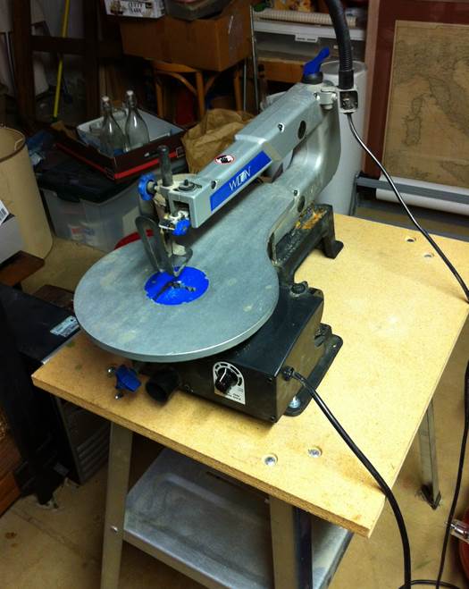
Just a quick update... I got all the templates cut out, mounted to the 1/16" plywood and cut out. I needed the motivation this project has provided to finally mount my scroll saw on the stand. As the article directly, I used the scroll saw to roughly cut out the templates and my belt sander to sand it to the final shape. Now I need a table saw. I saw one on Craigslist that looks like it will do the job. More tools! Never can have enough, really. Dan


-
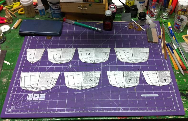
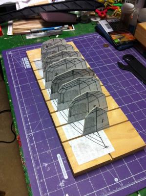
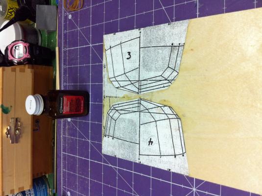
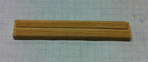
I started on the formers. Per the article, I copied the body plan eight times. I "fold[ed] each plan on the centerline and cut out [two] full-size body sections, using the baseline (at the top of each section of the plan) as the bottom of each former." The "baseline," Dr. Feldman refers to is, I'm assuming, the centerline marked on the half breadth plan above the body plan. That's what I used, anyway, and I think it's going to produce formers that look like those in Photos 4 and 5 in the article. His recommendation is to "rubber cement or spray adhere the body plan sections to 1/16" plywood..." I used Weldwood cement, which I'd always thought of as rubber cement. I must be wrong because there is no way those paper templates are coming off those formers now! I had a little error, early on and tried to remove a template from the plywood. No go. I sanded it off and you can still see the remnants in the photo. Spray adhesive might work better. Since these are just formers and will not be part of the finished boat, they need to be precise, but not pretty. One thing that would have helped me, as a first-time scratch builder, is a list of materials needed for the boat. I picked up some materials at Hobbytown yesterday. I'll keep a running total in case others are curious as to what's needed to build this boat. Three sheets of 1/16" birch plywood (6" x 12") @ $6.49/each Two sheets of 1/32" birch plywood (6" x 12") @ $4.49/each Ultra Light (0.56 oz) glass cloth (36" x 38") @ $14.39/each That's $42.84 so far. I wasn't sure about the glass cloth, but that's the closest thing they had to 0.75 oz./yard material referenced in the article. Dan (Sorry the photo's sideways. I couldn't figure out a way to rotate it 90°...)
-
When I got the most recent Ships in Scale magazine in the mail, I knew right away that I wanted to give the model on the cover a try. I've never built a scratch-built model before. I've never built -- or even played with! -- a radio-controlled boat before, let alone a radio-controlled sailboat. This little model just grabbed me and I decided to build one. It's small enough that I won't have trouble storing it. It looks simple enough for a novice scratchbuilder to complete and it looks inexpensive enough that, if I screw it all up, I'm not out a fortune. I haven't made much progress yet. I did manage to get the plans copied. I went to Kinko's to get the plans in the magazine scaled up to the proper size. They refused. They can't do something like that with copyrighted material. So I took the magazine to work and did it myself. After a little bit of experimentation, I found duplicating the image at 197% created a drawing with a 12" baseline, as called for in the article. I printed nine copies on 11" x 17" paper. That will give me enough copies to make the formers plus one other copy for reference. Next steps are the make a building board, make the formers and get a solid foundation to start building on. Dan

-
White glue throughout for me. I needed to redo many steps along the way and being able to simply dampen the glue and remove the offending part was very helpful. Dan
- 222 replies
-
- 1
-

-
- 18th century longboat
- model shipways
- (and 2 more)
-
I'm following your build with great interest, Cathead. I have Petsche’s book and your log is tempting me to pick it up and read it again. Dan
-
I was telling Kurt when I was over there, I started this project because I wanted to participate in the group build. As I've worked on it though, this little boat has grown on me. I think it's turned out really well and I owe a lot to the people on MSW and in the Nautical Research & Model Ship Society of Chicago. There were plenty of opportunities to put this model on the shelf and move along, but you all kept me at it and, for that, I'm really thankful. Dan
- 175 replies
-
- 3
-
-
- 18th century longboat
- model shipways
- (and 1 more)
-
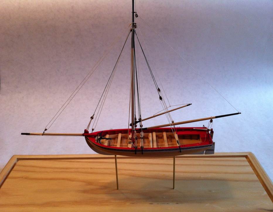
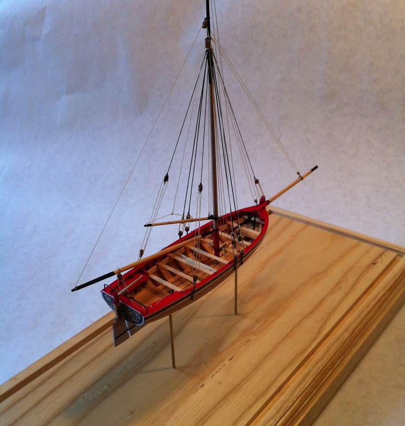
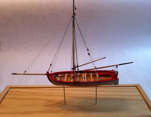
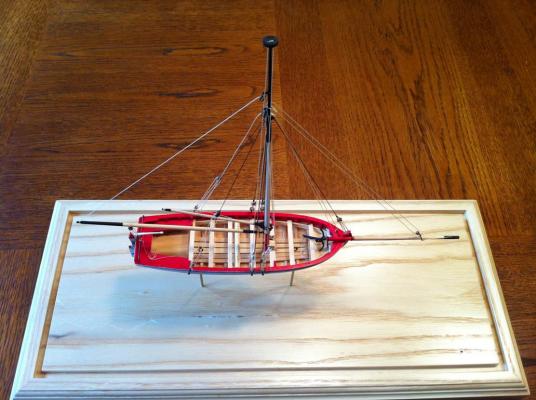
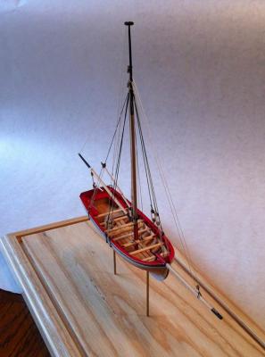
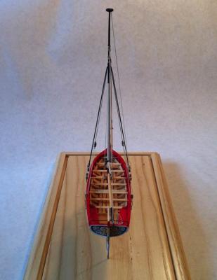
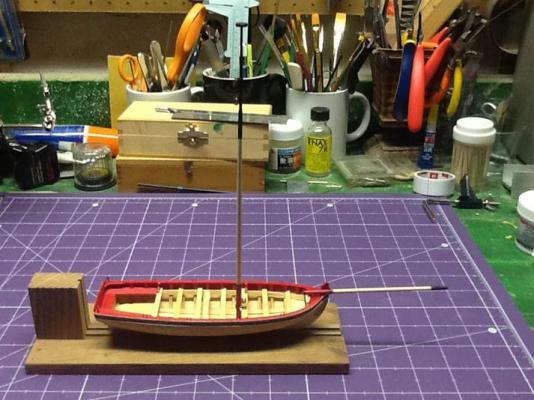
Kurt hooked me up. My drill press wasn't big enough to drill mounting holes in the middle of the plinth I had made, so I made a trip over to Westmont and he helped use his much larger drill press to get vertical mounting holes drilled. I tried other things -- guide blocks and alignment jigs -- but I wasn't convinced they were going to work and I only had one chance. Thanks again, Kurt! So, the model is essentially done. Bob Filipowski suggested I build some oar racks to display the oars and I think I'll do that, but now that the model's mounted, I wanted to spend time touching up the paint and finishing up some small details that are just easier to do when the model's mounted on the base. Here's what the boat looks like now. I wanted to get it in the contest in Manitowoc this year, but my son's First Communion is happening the same day. Not a hard choice!


- 175 replies
-
- 9
-
-
- 18th century longboat
- model shipways
- (and 1 more)
-
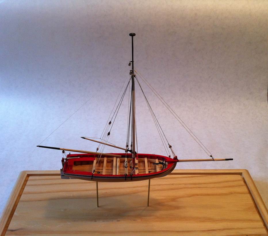
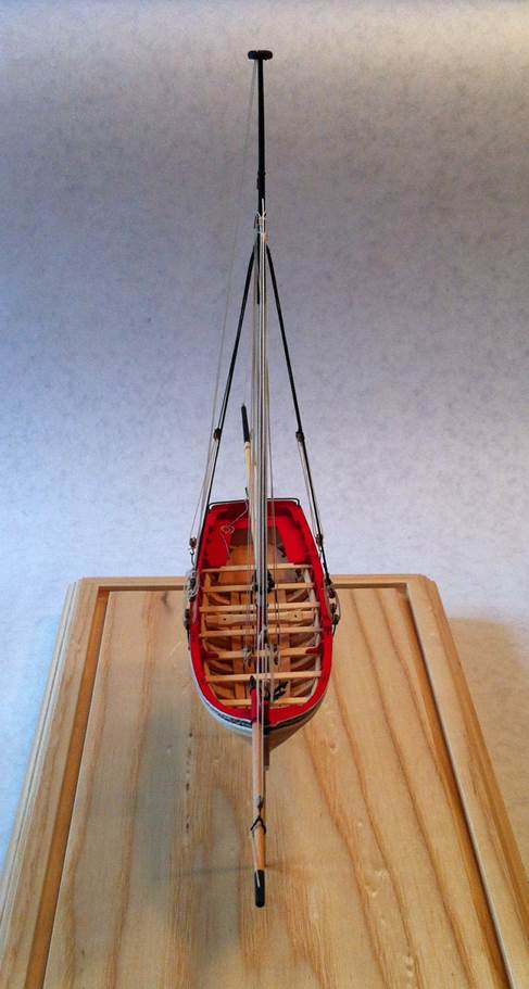
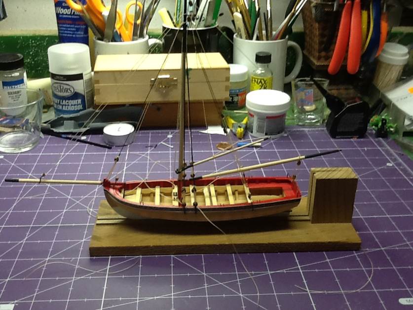
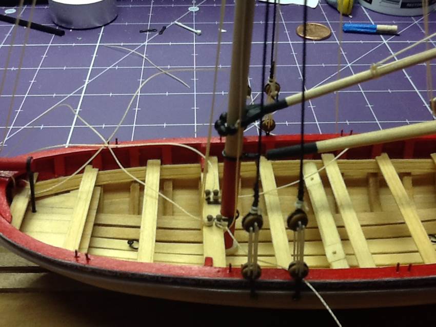
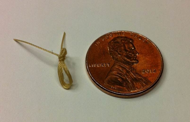
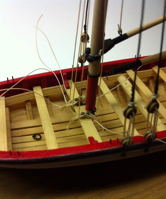
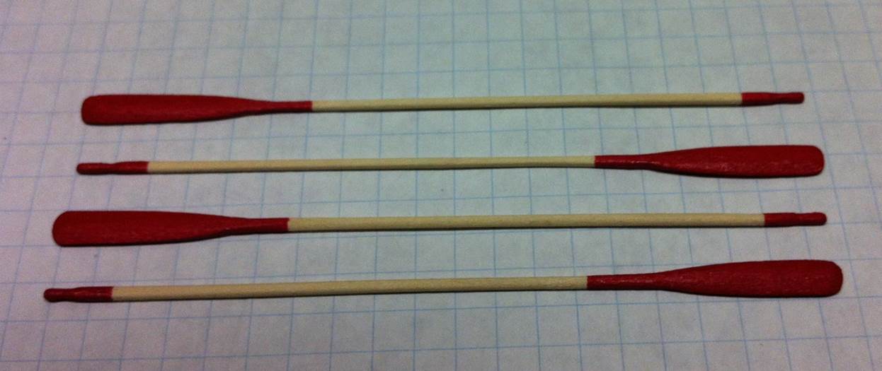
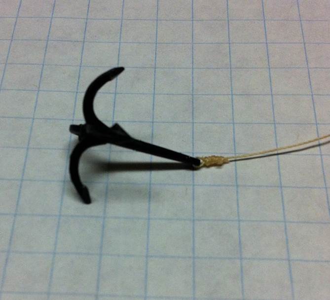
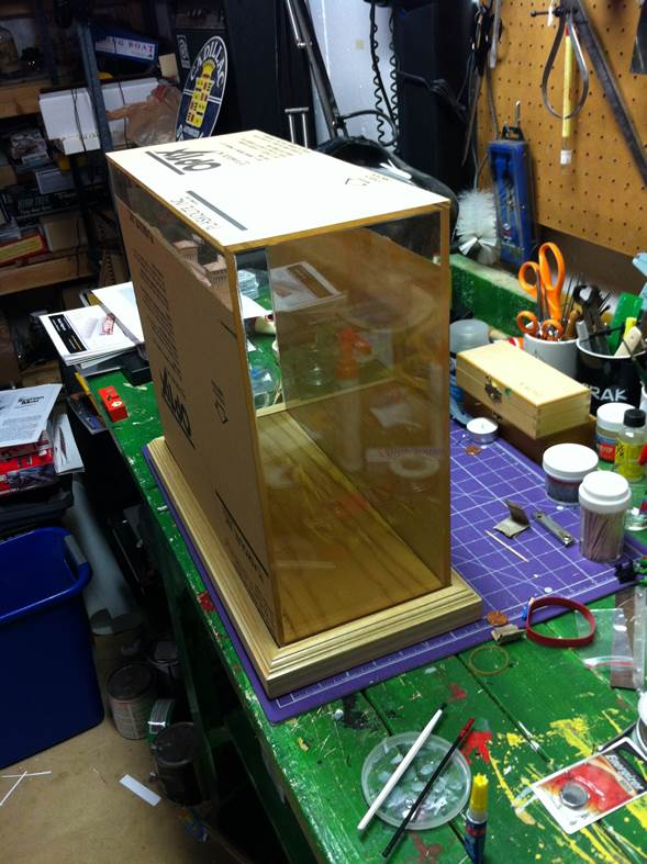
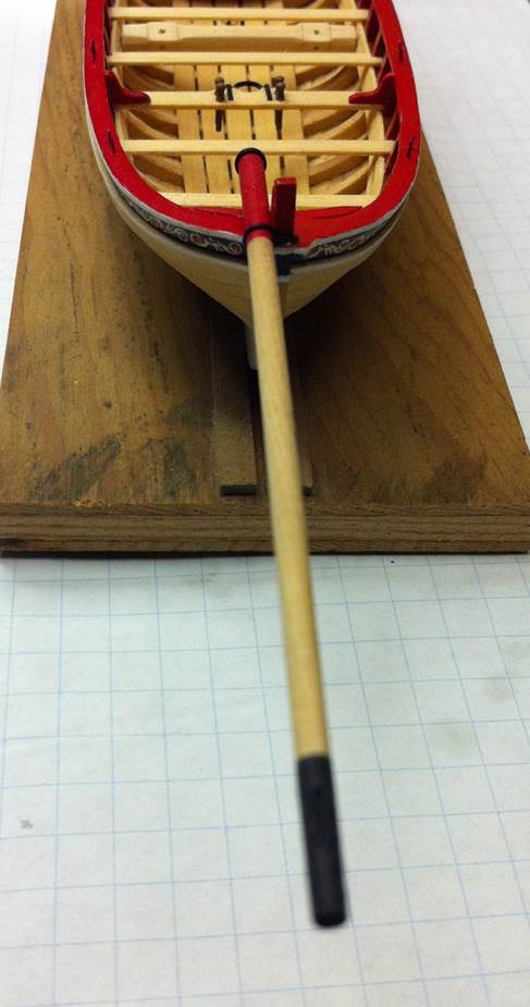
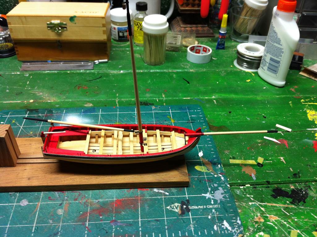
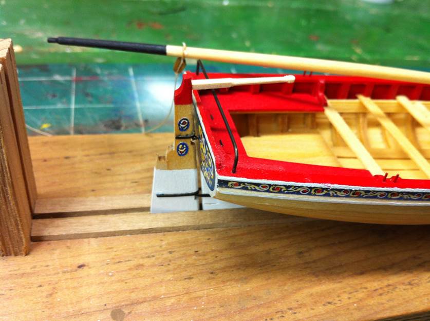
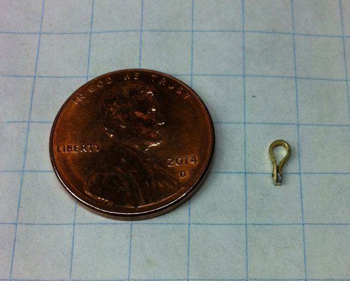
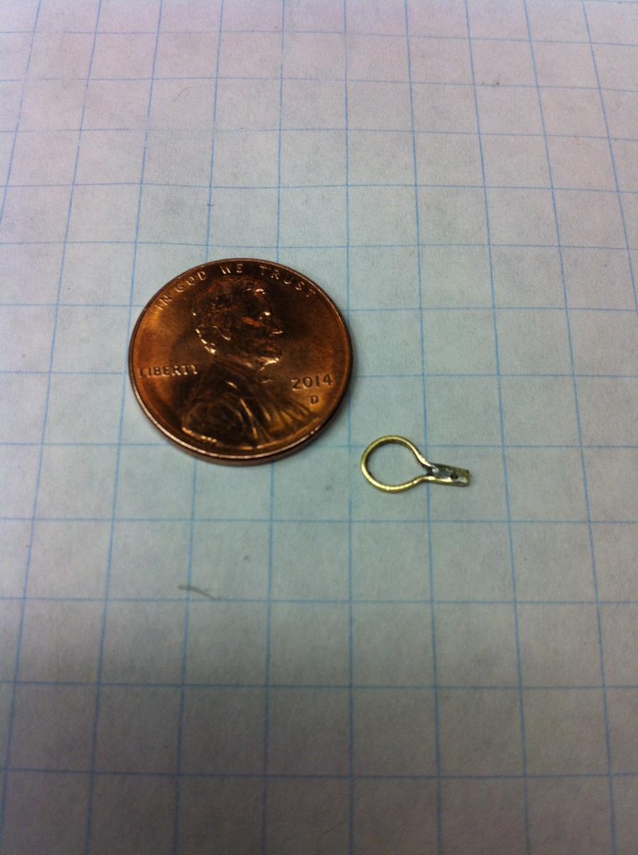
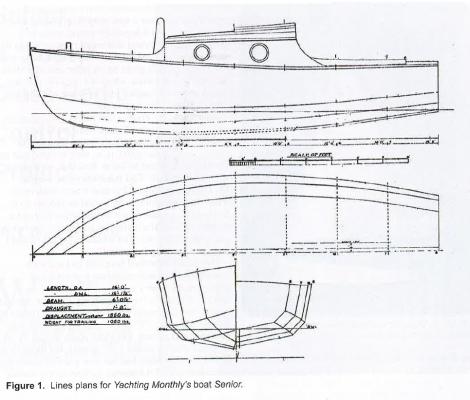
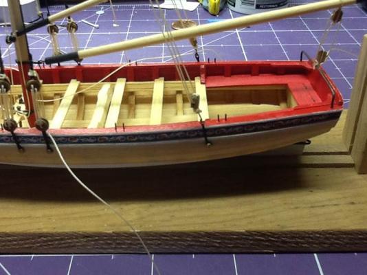
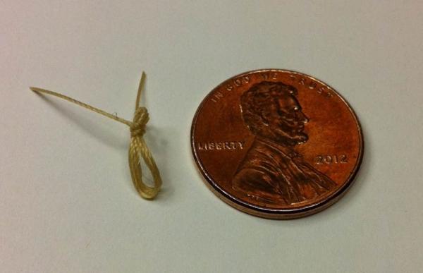
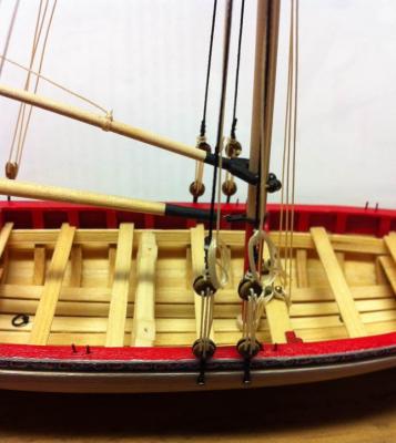
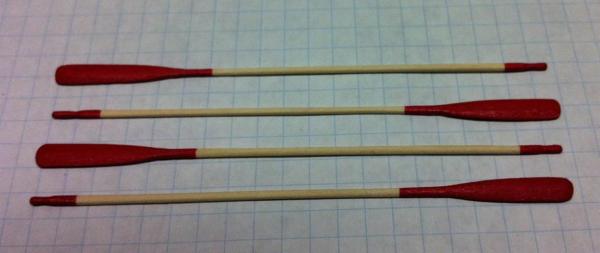
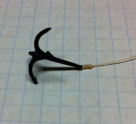
It's been a long time since I posted any progress on the longboat ... but that doesn't mean there hasn't been progress! It's almost done. I've found taking pictures at this stage to be difficult. Sometimes it's tough to get the camera on my phone to focus where I want it. I wind up with great resolution on stuff I don't care about. Since I last posted, I've rigged the boat. There's a deceptive amount of rigging on this model. I expected it to go faster than it did. It's not all that difficult; there's just a lot of fiddly little things to do. In no real order, here are some photos of my progress. I spent some time making the chainplates. In the end, I had to do it a couple of times to get good-looking ones. I thought they turned out pretty well. I had some trouble withe the rope coils. I went into that little job thinking I'd knock it out in an evening. Not really much to those things. I have a little jig I use for wrapping them. Then I hit them with hairspray to keep them together while I'm working with them. Plunk them on the model and you're done, right? Here's a typical one: But when I added them to the model, they just looked ... wrong! So I re-did them in a lot less complex way. I'd left a lot of extra on the actual rigging line, so I just wrapped them into a coal, coated them with some white glue and weighted them down a little with a dental pick. That gave the illusion of weight and the coils looked a lot more natural. I had trouble taking pictures of those things, but you can see the same effect in the coils on the flag halyard. Speaking of the flag halyard, I got it all rigged, as shown in the picture, and realized that, as I tied them down, I'd wrapped them around the shrouds, on both sides. It was actually hard to see. (You can kind of see it in the photo.) But once I noticed it, I couldn't leave it that way. I un-rigged it and did them again. They look a lot better now. So what's next? The oars are done: As is the grapple. I got the case back from the guy who made the base for me. That was a little story. I don't have a table saw. I found a guy with a millwork shop right across the street from where my kids take karate lessons. I thought, "Look at that! I can help a local business, get my base made and do it without making a separate trip because I'm at the karate dojo at least twice a week anyway." He was a nice-enough guy, but he told me it'd be done in two weeks and took more like five. And it wasn't cheap. If he'd gotten it done on time, I wouldn't have had too much trouble with the price, but making me wait? I felt a little ripped off. Add to that the fact that, at about week four I started calling him about it and he wouldn't return my calls... Anyway, it's done and it looks really nice. So I have to install the oars and the grapple. Haven't decided if I'm going to put the arm on the windlass. Then I'll mount the model on the base and do a little touch-up of some spots where the paint's been marred by handling it, put a little brass plaque on the base and finish it off. Dan


- 175 replies
-
- 6
-
-
- 18th century longboat
- model shipways
- (and 1 more)
-
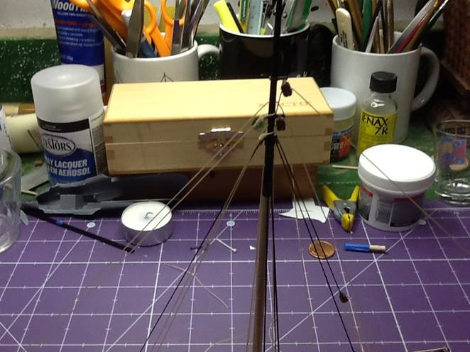
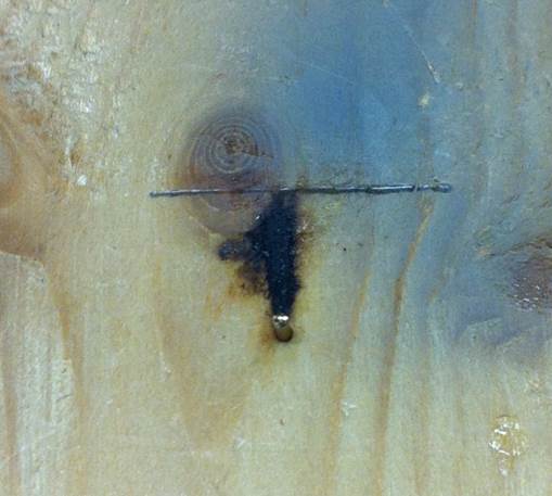
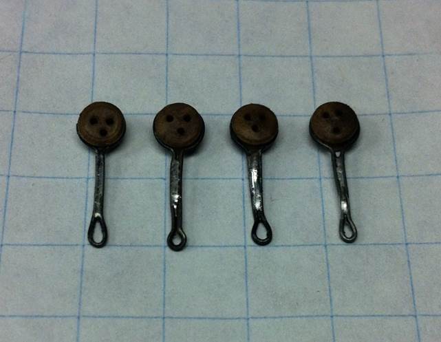
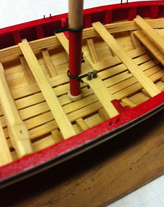
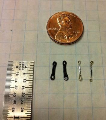
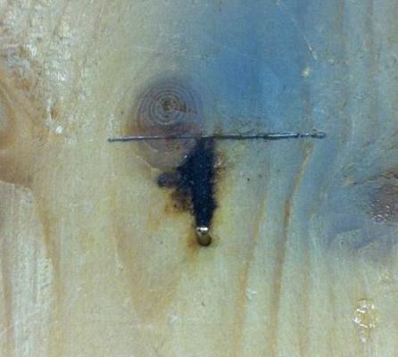
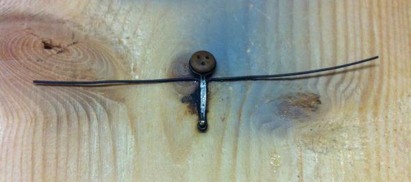
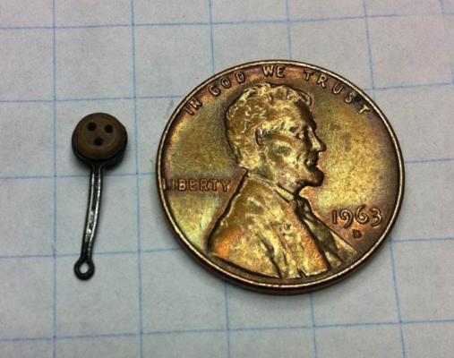
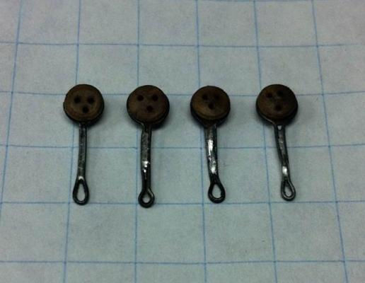
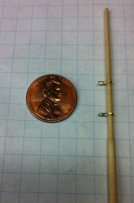
I spent a little more time with the Longboat last night. I decided on the height of the pedestals: 2.5". I made this determination in a highly scientific manner. I raised the model above the base -- with a ruler next to it -- until I liked how it looked. So here's how it all worked out: I deviated from the instructions a little bit by making the chainplates before I stepped the mast. I followed the instructions pretty closely, except that I soldered everything rather than use CA glue. Here's the super-complex jig, a brass nail with the head cut off. You can see the scorch marks from the soldering iron and the measuring line to show where to bend the wire. And here's a chainplate being made. The in-process one is below the finished one to show how it all works out. These are little things... Here are all four. They still need to be painted. And then I stepped the mast. It took a couple of attempts to get the mast step to look right. I think this is pretty close. Tonight I'm going to do a little more beveling on it. It looks a little too blocky to me as it is. I drilled a small hole in the bottom of the mast and a hole through the mast step. I ran a wire through the mast step and into the bottom of the mast, giving me a little spike on the bottom of the whole assembly that helped me line everything up. The mark made by the wire showed me where to drill the hole and step the mast. And here's how the boat looks now. The gaff and boom are completed. I need to make the other two chainplates and then start rigging. Also have to get a base for the case made. Coming right along! Dan

- 175 replies
-
- 8
-
-
- 18th century longboat
- model shipways
- (and 1 more)
-
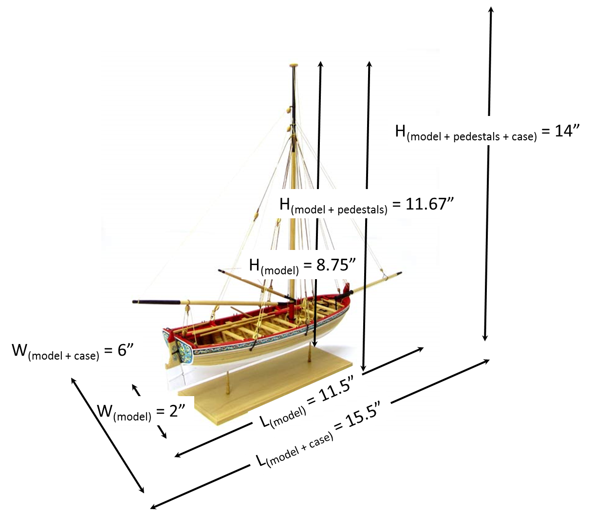
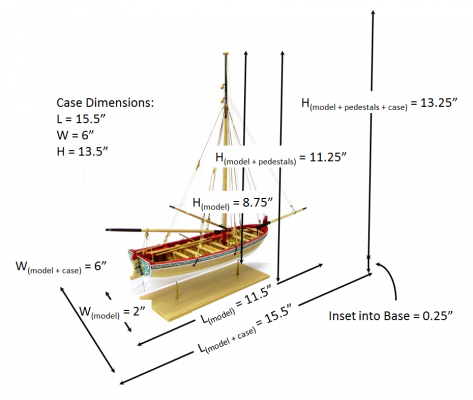
Thanks, Kurt! Here's a question for everyone. I've gotten to the point where I want to order the case for the model. I know I want to have 2" of space all the way around. (I've seen a lot of cases and that seems to be the amount of space that looks best.) So to do that, I made a drawing and put the dimensions on it. But here's my question. How high should the pedestals be? I started out thinking they should be about a third of the total. So if the model is 8 - 3/4" high, then the pedestals should be about 4 - 3/8" for a total height of 13 - 1/8". That seemed pretty high, so I recalculated at a quarter of the total. That gave me pedestals 2.92" tall. (Model = 8.75"; Total height = 11.67") That sounds better and makes the case only about 14" tall (plus the thickness of the base). Any other way I should be thinking of this? Any rules of thumb you all go with? I realize that this is a matter of choice to some extent. I like the looks of the taller pedestals most have used, but I don't want to make them so long that the model looks like it's escaping from the base. Dan

-
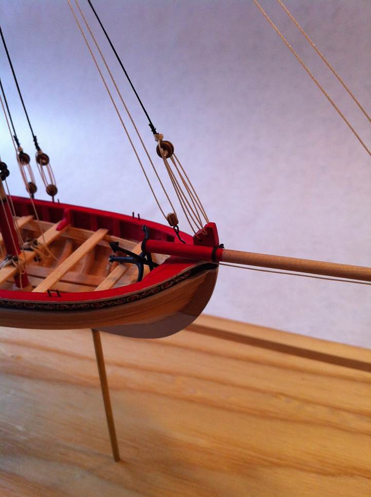
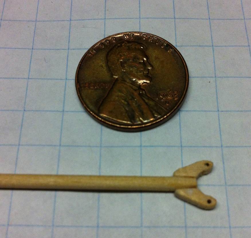
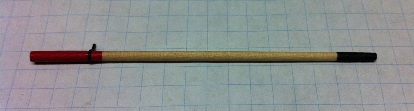
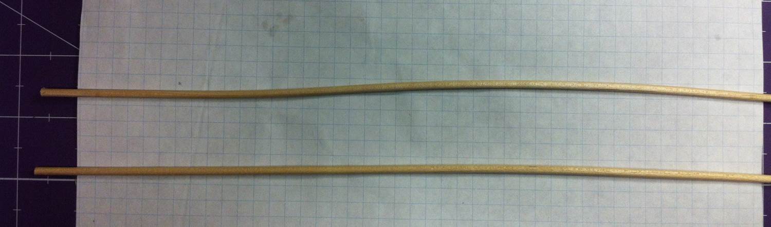
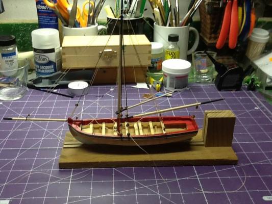
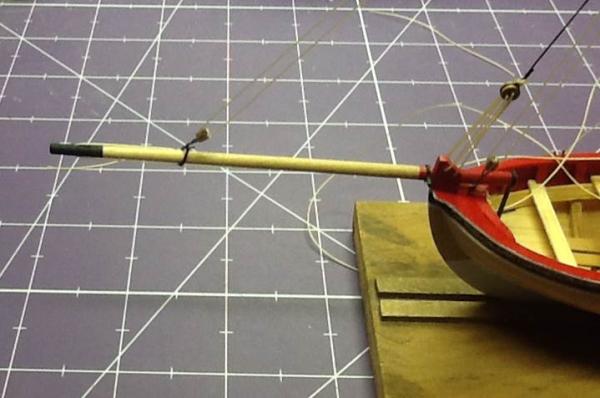
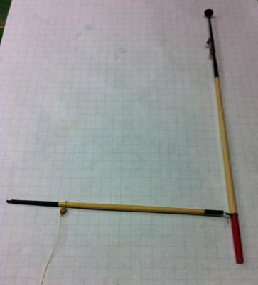
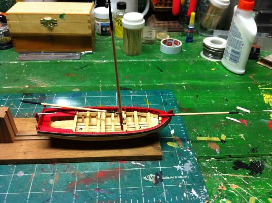
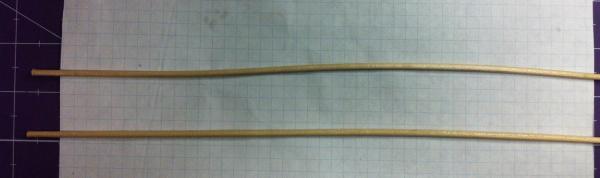
The mast, boom and bowsprit are done! The gaff is almost there. I can see the completion of the longboat from here... I've been happy with the quality of the materials in this kit with two exceptions so far. First, the dowels were warped, which meant I had to spend all of $0.18 at Hobby Lobby for new ones. The second quibble is with the quality of the line. The kit comes with polyester rigging line. I tried to use it, but it wouldn't behave like I wanted it to. No matter what I did, it seemed to retain the bends that were in it from the little card it comes on. It's heavier than I like, too. Instead of using it, I just started using some nylon line I've used in the past and like. After watching Chuck demonstrate his line-making technique in St. Louis, I went out and got some linen crochet thread. I'm going to try that out and see what I can come up with. Chuck's got a source for tan thread. I don't, so I'll wind up dying the off-white stuff I did find. I wish I'd been able to videotape Chuck's demo. I know I've forgotten parts. So, on to the construction stuff. I wasn't very good about taking pictures of the boom as I went along. No big deal, really, as there isn't much to it. I turned it on my lathe, as I normally do and here's the result. I tried to seize the two blocks on the mast using the kit-supplied line, but ran into trouble. I couldn't get it through the tiny holes I drilled in the mast bands. I used fly tying wire instead, but didn't like the result. After seizing the block onto the boom -- and liking the result -- I cut the blocks off the mast and re-did them with the nylon thread. They look better now. It took me a while to figure out how to mount the bowsprit. I wanted the pitch of the bowsprit to be correct, for it to be true fore and aft and have the sheaves vertical so that the rigging will pass fair through it. I installed a small pin in the side of the bowsprit that fit into a hole in the stem. It would still move up and down and side to side, but fore-and-aft movement was stopped. Then I installed the bowsprit support. Then I installed the bowsprit itself. You can see the pin run through the forward band into the stem. That's going to get cleaned up and painted. And then on to the gaff. I turned the dowel on the lathe and carved the land into the end. Then came making the jaws. They're tiny and I wanted to make sure they were symmetrical and the holes were in the same place on both sides. I traced the outline of the jaws -- from the plans -- on a piece of paper, cut it out and glued it to a piece of stock. Then I cut a second piece of stock and clamped the two together. Then I drilled the holes. To keep everything lined up, I ran a piece of wire through the holes. Between the little clamp and the wire, everything stayed stable while I carved the jaws. Here's a photo of the half-carved jaws. After they were carved, I just attached them to the gaff using white glue. I installed the eyebolt too. Next step is paint and then rigging it. Hopefully I get to that tonight. It's all coming together... Dan


- 175 replies
-
- 5
-
-
- 18th century longboat
- model shipways
- (and 1 more)
-
Thanks, Ryland and John! It was nice to put a name with a face in St. Louis, Ryland! Dan
- 175 replies
-
- 1
-
-
- 18th century longboat
- model shipways
- (and 1 more)
-
Thanks, Michael. That jig looks like a really useful tool, too. Making spars from square stock probably allows you to find straight-grained material to work with. Dan
-
Sorry for the delay, Steve. I haven't been attending to Model Ship World as attentively as I should. How did I get the mast lined up? I simplified. I got the table as close as I could to the drill chuck and still have enough room to chuck in the drill bit. I used an awl to make a small mark where the holes should be. (I just did that by eye.) The carbide bits are nice because they have a nice point on the and the won't wobble. The cheap Harbor Freight bits don't, so they're tougher to use. Without the drill press running, lower the bit into the hole, making sure the bit is lined up. This is the equivalent of "measure twice, cut once." When you're satisfied that everything is lined up, drill away! My mistake was using the drill press vice, which made alignment harder. Take your time and it will work fine. Dan
-
Thanks, Toni. I thought the same thing about using the drill press. I don't think it's a good solution for every job like this. For instance, I think I'd prefer to use the lathe to turn a spar. Tapering both ends of a dowel in a drill press sounds like an impossibility, especially when you do it like I do, with a template and a digital caliper. For this job, the dowel didn't whip around much, so it worked out. (It's short, which is probably why.) I made a wood strip organizer out of an oatmeal box and some paper towel cores. (You can see it on the right side of my workbench.) That was a suggestion from Kurt Van Dahm and it worked out really well. Off to Hobby Lobby to get some more dowels... Dan
- 175 replies
-
- 1
-
-
- 18th century longboat
- model shipways
- (and 1 more)
-
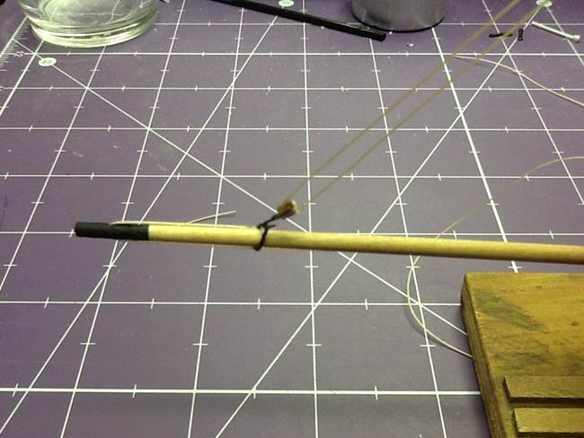
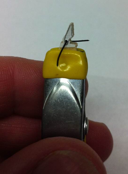
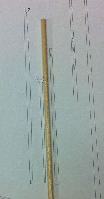
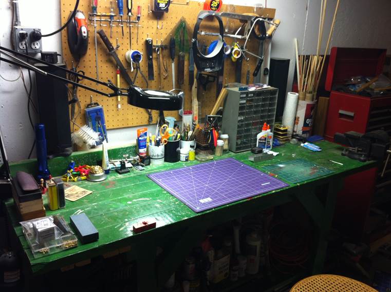
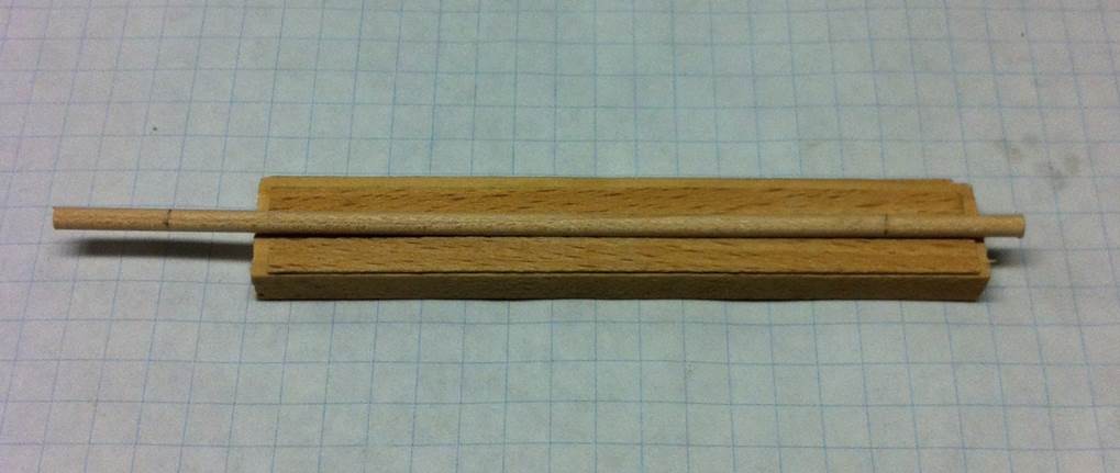
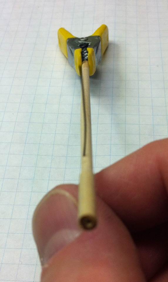
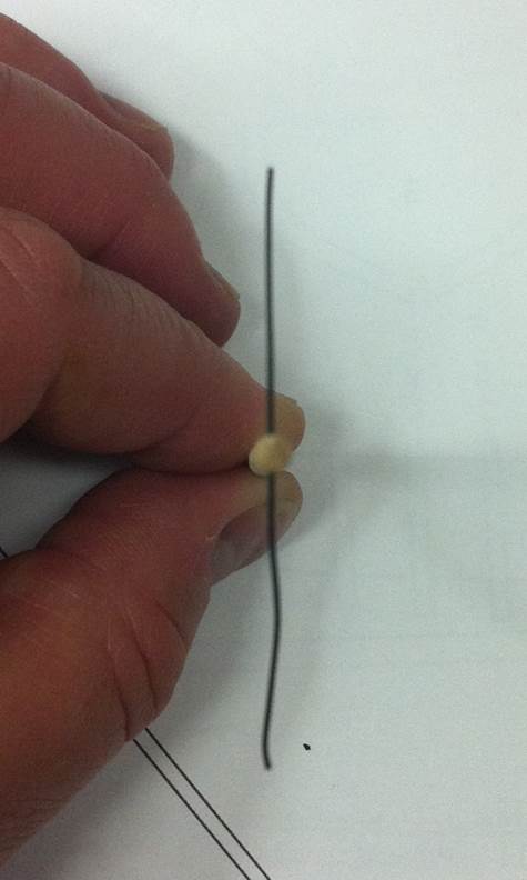
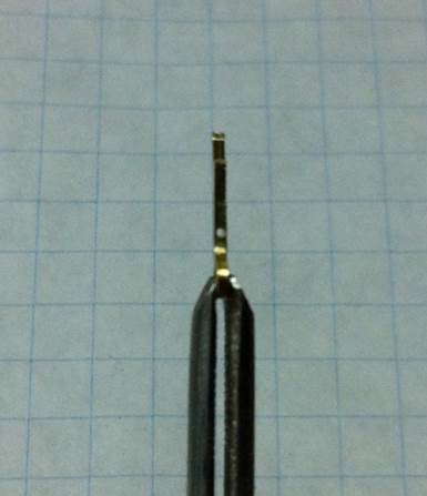
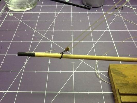
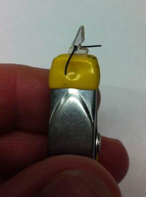
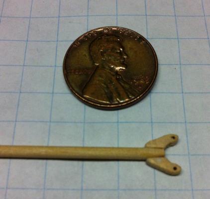
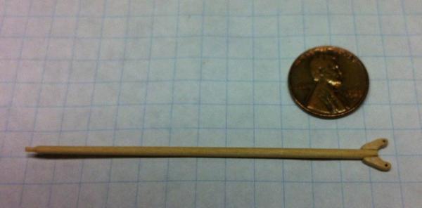
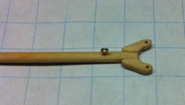
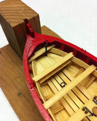
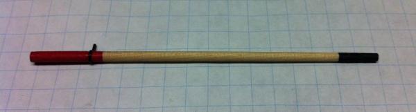
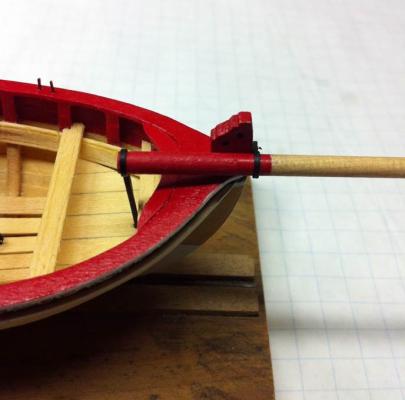
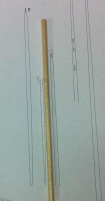
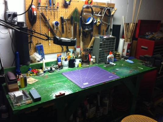
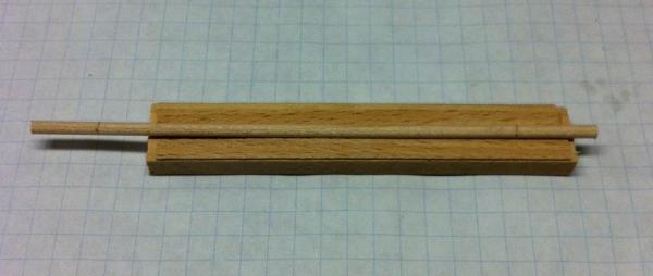
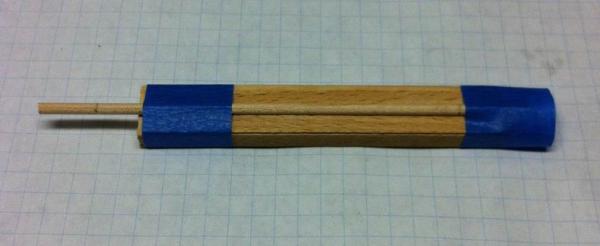
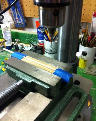
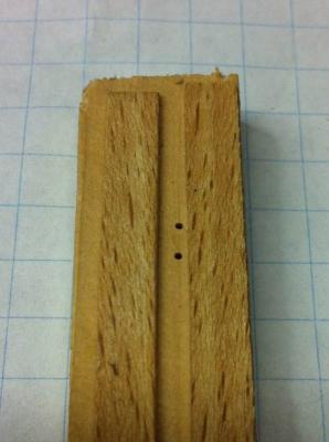
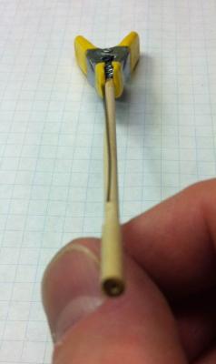
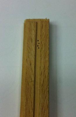
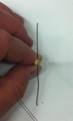
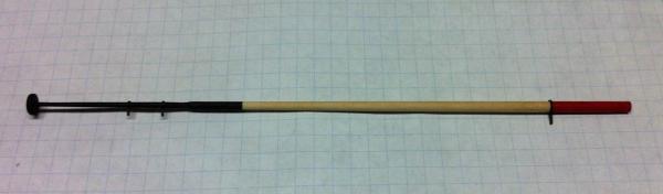
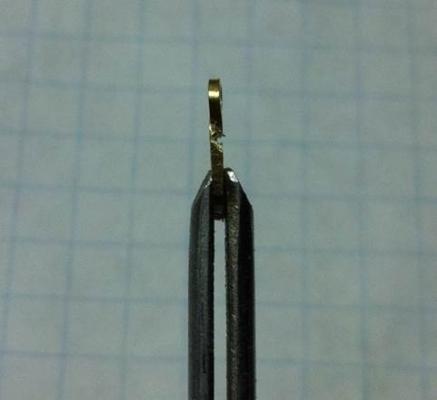
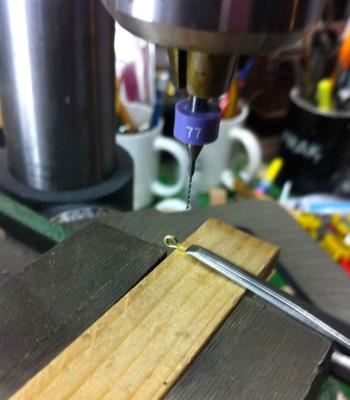
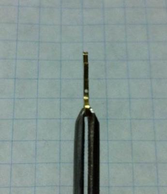
Last weekend, I attended the annual Tri-Club meeting, a gathering of the three Chicago-area ship modeling clubs. I had a great time, saw some terrific models, heard some great presentations and talked with some really knowledgeable model builders. I also scored a parts organizer which someone threw on the table for free. It has found a good home! I wish I'd taken a picture of my workbench prior to spending some time organizing it. Here's what it looks like now. The improvement is dramatic. Now, with a nice clean workbench, I started on the bowsprit. I have one little quibble with the materials in the kit. Get a load of the 1/8" dowels from which the bowsprit, gaff and boom must be made. Looks like I'm going to need to replace that because there aren't enough straight sections to make the parts from. I did manage to find enough straight stuff to make a bowsprit. I made a little jig to make drilling the holes for the sheave easier. On the mast, I just eye-balled it. That worked, but I wanted to use my new carbide drill bits and, because those things don't flex at all, I thought it would be better to put them on the drill press. The jig is just a couple of pieces of scrap wood to hold the stock in place. I taped it down to keep it from moving around and then put it in a drill press vice. That thing is going nowhere! So off I went, drilling happily along. I knew something had gone horribly wrong when I pulled the stock out of the jig. Notice how off-center those holes look? I really did try to line that up properly and I had the drill press vice clamped to the table, so it didn't move. Must have just been the angle I was looking at it that made it look centered on the top of the stock. It didn't get any better when I looked at the bowsprit. (This was tough to photograph, so I ran a little piece of black wire through one of the holes to show how off-center they were.) I figured that, if I left it that way, anyone sighting down the centerline of the model would notice the asymmetry. This needed to be done again. Second time was the charm. See those holes down the center of the jig? And here's the final product, a much better result. I had tried, with the first attempt, to turn the bowsprit on my lathe, but the truth of it is that's just overkill. The taper on the bowsprit is not very severe and using the lathe is time consuming. I tried a technique Doc Williams has suggested. I chucked the stock in the drill press and just used sandpaper to sand it down to the final dimensions. That worked really well. I painted the aft end of the bowsprit and left it to dry last night. The forward end will get done tonight, along with, probably, the aft iron band. More pictures to come. Dan
- 175 replies
-
- 3
-
-
- 18th century longboat
- model shipways
- (and 1 more)
-
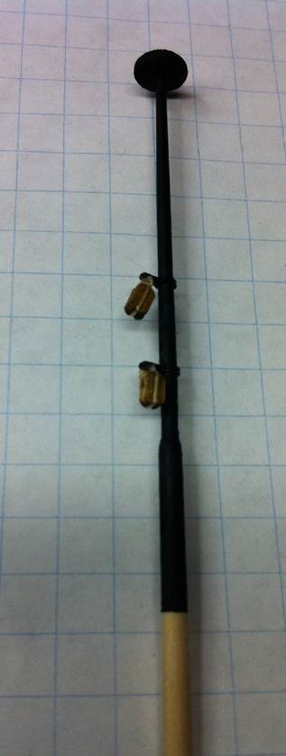
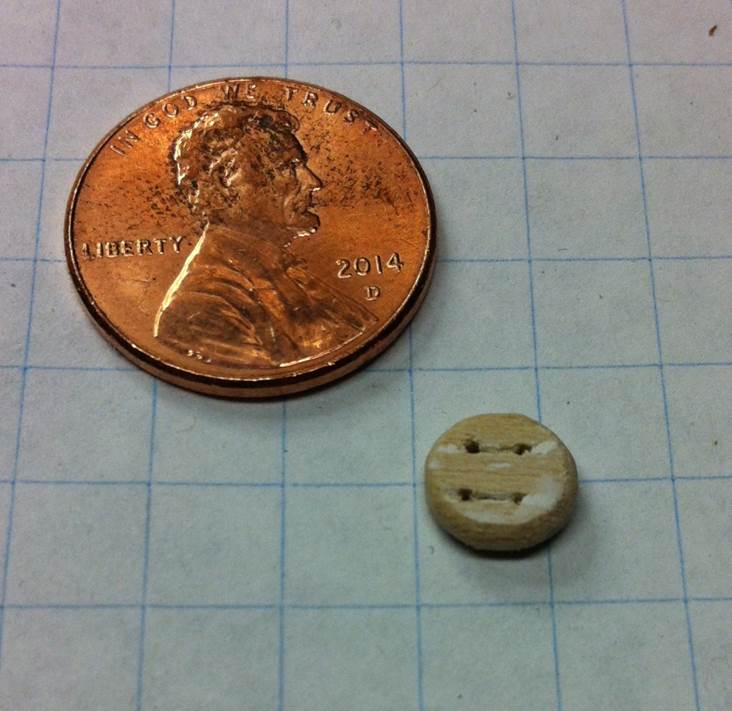
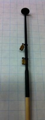
Made a little progress over the past week or so. I made the ball truck. There's not too much to that, just a lot of sanding to get the proper shape and thickness. I had a take a couple of runs at getting the holes drilled in a proper square. As you can see, there was some wood filler involved. And then I assembled the whole thing and completed painting it. The mast is finished! Dan

- 175 replies
-
- 3
-
-
- 18th century longboat
- model shipways
- (and 1 more)
-
Thanks, Toni and David. I found the website to buy replacement bits in packs of 5: http://drillcity.stores.yahoo.net/5pacresdrilb.html I'm guessing I'm going to have those early next week. I made the second (smaller) band without any trouble at all. "This is easy!" I thought, and went merrily along into the third one ... and this happened. The first hole I drilled with just the bits, turning them like a pin vice. For this one, I used the Dremel, but was unable to hold it straight and steady enough to drill precisely. (I have an old Dremel from the 1980's. The newer ones are much less bulky.) The brass strip is only 1/16" wide, so any error is going to make drilling the hole difficult. Taking Toni's advice, I got out my drill press. It's not a hobby drill press, so it's big for the job, but it is very stable and I have a nice drill press vice for it, so I can hold a workpiece steady. As with most things drill press, setting the machine up takes more time than the actual work. Here's the set-up: And here's the final product: A little trimming and dressing and I had this: Just to check fit, I put them on the mast. Looking good so far. Now I need to make the ball truck install everything and paint the mast. Dan

- 175 replies
-
- 2
-
-
- 18th century longboat
- model shipways
- (and 1 more)
-
I snapped off the #76, Bob. Thanks for the offer, but I dropped an email to Drill Bit City to see if I can just buy the single bit. We'll see what they say. Started on the other two bands tonight! Dan
-
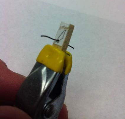
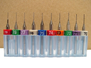
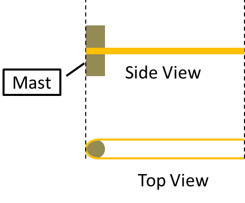
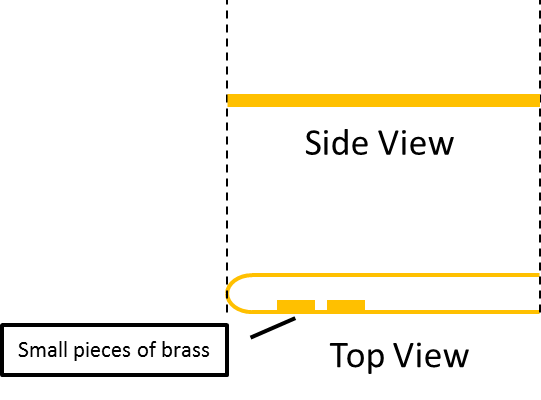
Progress! First, I want to put in a plug for Drill Bit City. I ordered a set of carbide drill bits (shown below). I swear, I hadn't even hit "Send" before they showed up on my doorstep. I ordered them on Monday night and had them on Wednesday when I got home from work. I was figuring I'd have to wait a week to get them, so I was thinking about what I could do in the meantime to make the bottom mast band. I thought, what if I soldered some little pices of brass on the strip and made a hole instead of drilling one? Like this: Step 1: Bend the brass strip around the mast. Step 2: Solder small pieces of brass on the strip with a gap between them. The crimp the strip around the mast and solder everything together, leaving a hole. (I figured I'd have to drill down through the soft solder, but that wouldn't be a problem and I wouldn't have to twist the brass strip to make a flat surface to drill down through. So that's what I did. And here's the result, after trimming the ends off and dressing everything with a file. As usual, no operation goes flawlessly the first time. I did damage one of my brand new drill bits. (Note: carbide does not flex!) Once I learned my lesson, the rest of the drilling operation went perfectly. I love those drill bits. They made quick, accurate work of this job. I probably over-thought this -- nothing new for me there! -- but it was an interesting problem to solve. The other two bands are simpler because you just have to bend the strip around the mast, solder and drill, so a lot less thinking involved in those! With all this practice, I'm getting a lot faster and more accurate with soldering, too. Dan

- 175 replies
-
- 2
-
-
- 18th century longboat
- model shipways
- (and 1 more)
-
Really terrific work! Congratulations! Dan
-
Toni, I used two different bits. The first was a dental drill given to me by Marc Meijer, the kind used for root canals. That one at least made a dent in the brass, but couldn't cut through. The second was a regular high speed steel drill bit. I got that as part of a set from Harbor Freight Tools. Admittedly, those are pretty cheap drill bits, but I got nothing from it. Nothing at all. I used a pin vise first, then chucked them into my Dremel. (I used my cheap Harbor Freight rotary tool, too, but that one wobbles around so much it's useless for any kind of precision drilling. It's alright for sanding, though.) I've got another set of precision drill bits, but I don't know if I have one small enough to do this job. Might have to go to drillbitcity and buy some high quality bits. So you solder the band after you've fitted it on the mast? I'd be afraid I'd scorch the mast doing that! Dan