HOLIDAY DONATION DRIVE - SUPPORT MSW - DO YOUR PART TO KEEP THIS GREAT FORUM GOING! (Only 24 donations so far out of 49,000 members - C'mon guys!)
×


dcicero
-
Posts
267 -
Joined
-
Last visited
Content Type
Profiles
Forums
Gallery
Events
Everything posted by dcicero
-
Someone, I know, has a good answer to this one... I'm building a small boat model. (It's the Bluejacket Skiff.) I'm making the sail for it now and would like to add a number to it, as every small boat used for dinghy racing has. What's the best way to do that? I'm using a high thread count cotton, as recommended by Steve Wheeler in an article he wrote in the April 2004 Ships in Scale. His model didn't have a number on the sail, though. Iron-on transfers? Dry transfers? Some other technique? Just wondering what others have done. Dan
- 8 replies
-
- 2
-

-
- small boat
- sails
- (and 1 more)
-
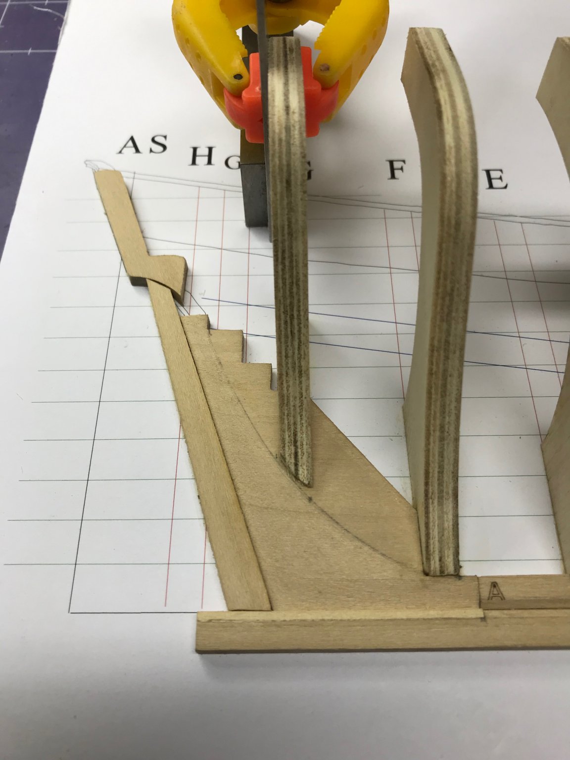
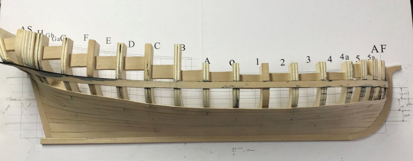
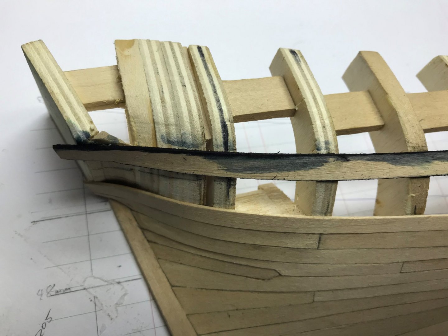
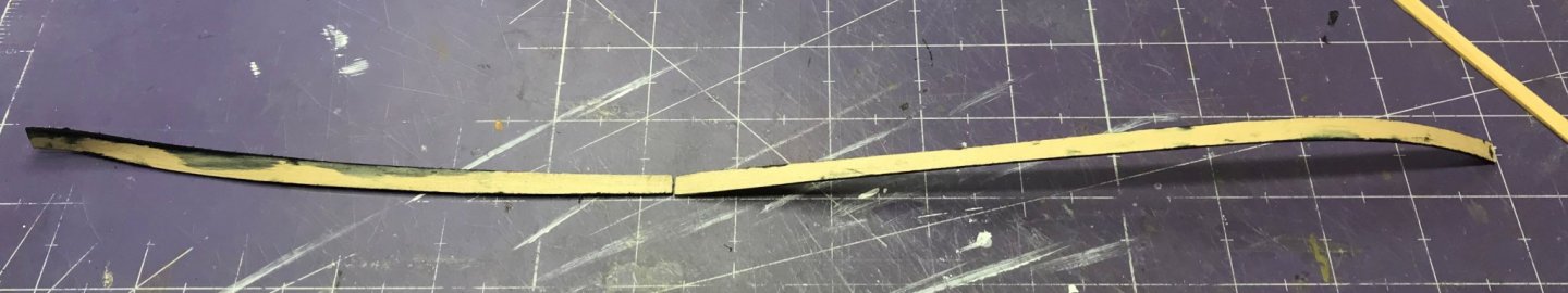
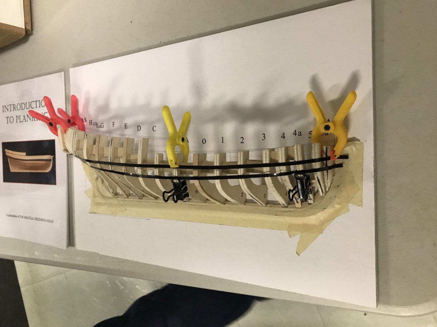
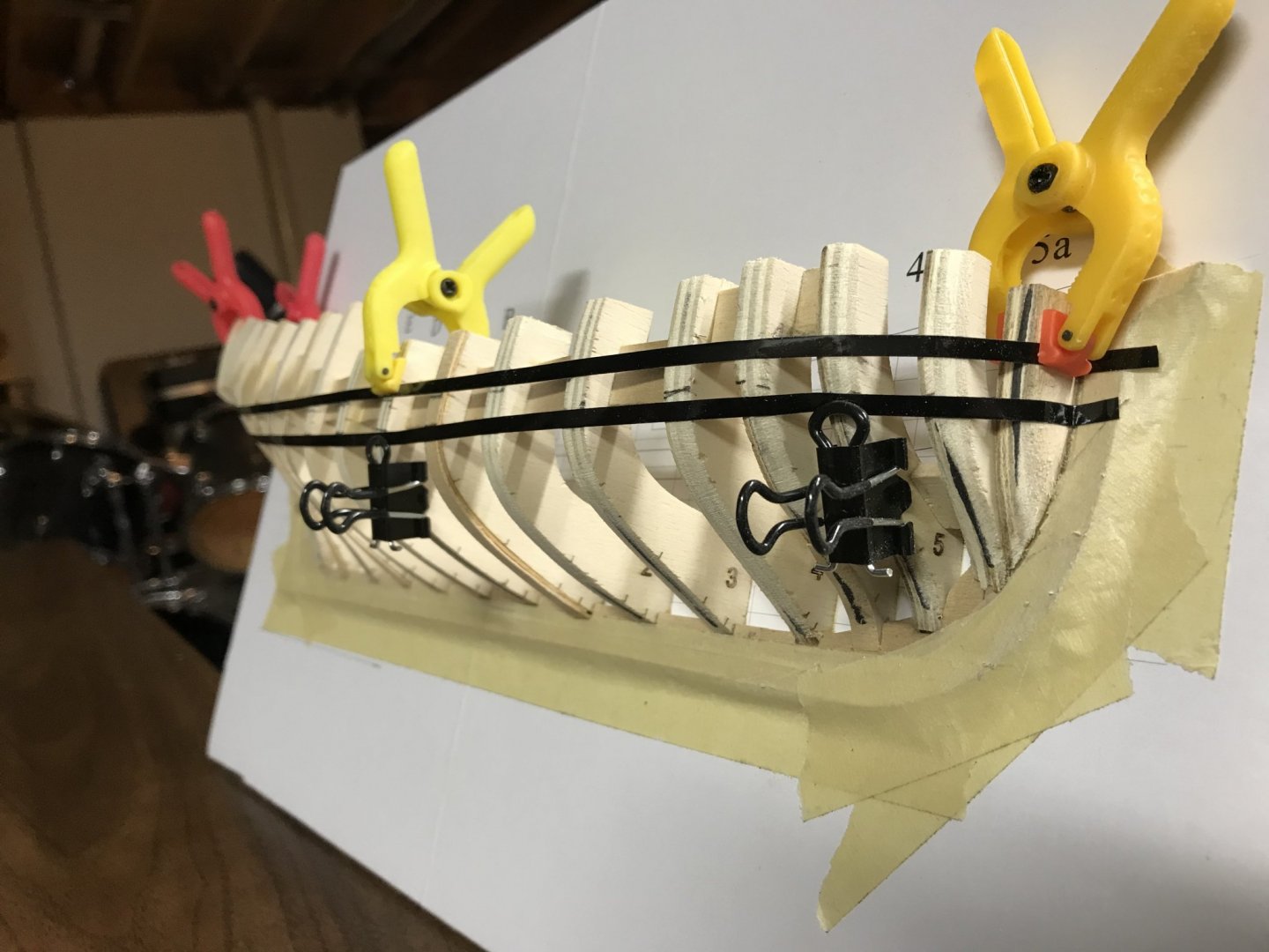
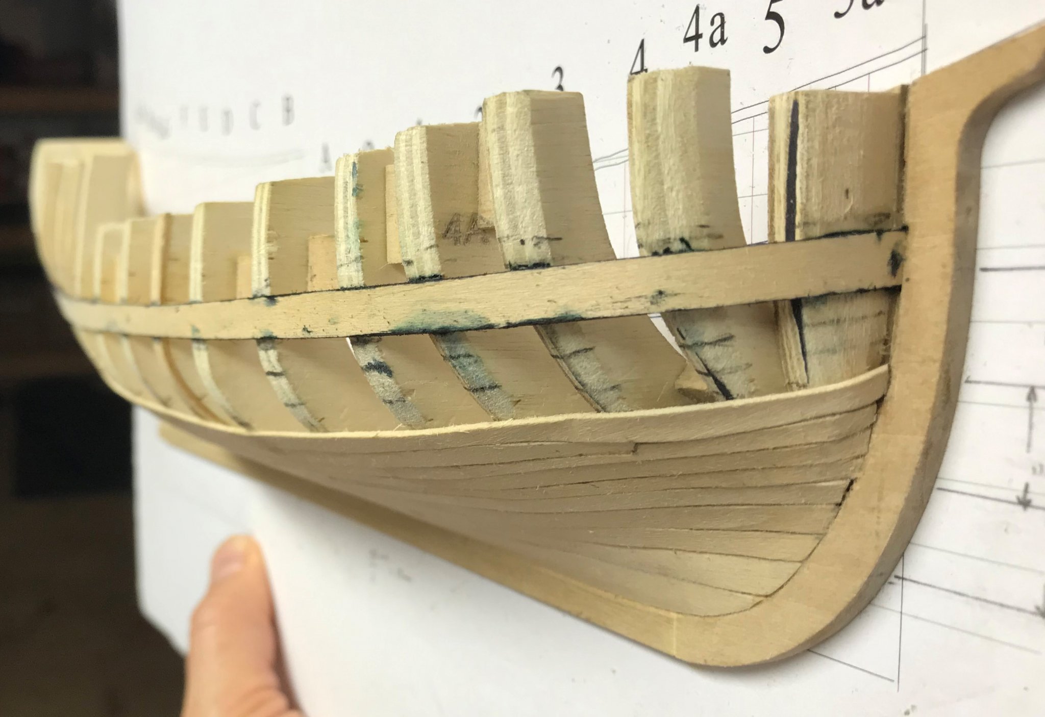
I know it's been a while since I posted any updates. I have made progress! You can see here the second planking belt completed and the first layer of the wale installed. It took me a couple of tries to get this right, but I was pretty happy with how it turned out. Notice anything weird? All that black staining? The instructions recommend using an archival marker to stain the edges of the wale, so went over to Hobby Lobby and bought one. I was really happy with how that went. It looks like paint and is a lot less hassle. I'd fitted the two pieces of the wale by wetting them, clamping them in place and letting them dry. I removed them, used the marker and then let them dry for a day before reinstalling as you can see here. Every time I touched the model, some of that black ink would come off on my hands. I tried cleaning it off with a cottom swab and you can see the result below. What a mess. I'm so close to finishing this project off and the last thing I wanted was to ruin everything by bleeding black ink everywhere. I decided to remove the wale and make a new one. I used the old one as the template. Even though I've removed the wale, there is still a little of that black ink on the frames. I've been carefully removing it, but that looks to be a project that's going to take a while. Anyone got any thoughts on where I went wrong? Dan


-
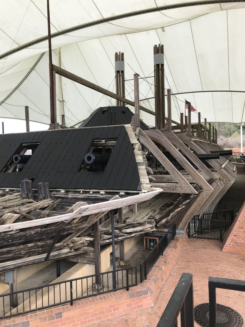
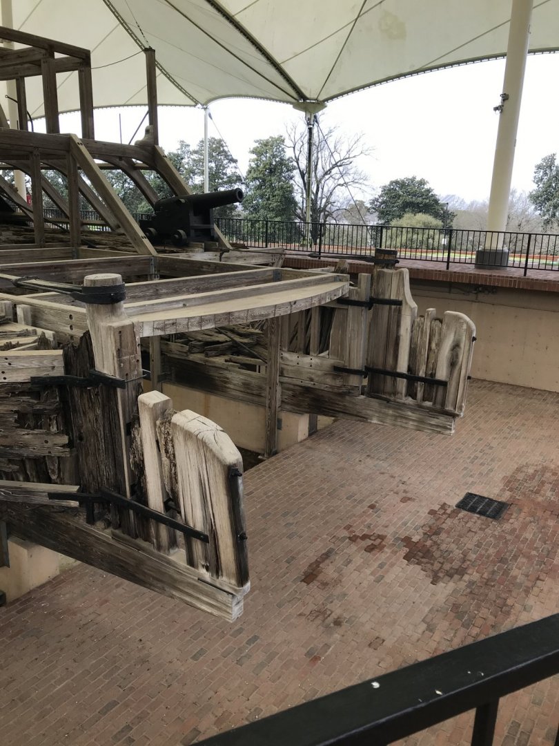
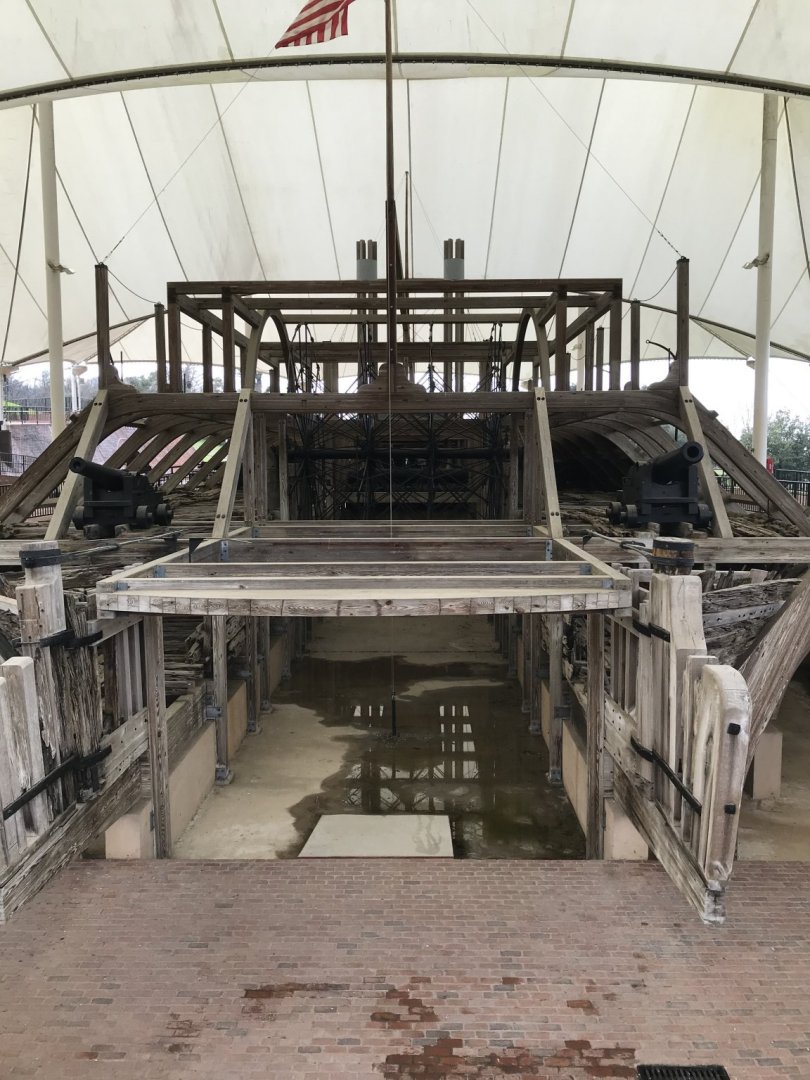
Not a lot of thought given to crew comfort in those ironclads, Brian. You'd made a point earlier about armor plating and I swear I'd read that armor was added to the forward casemate and pilothouse in light of battle experience. As I recall, after actions up the Cumberland and Tennessee rivers -- Forts Henry and Donaldson and Fort Pillow -- the need for that armor was clear. The boats would form up in line abreast, with only their forward guns bearing on the enemy batteries. They took a lot of punishment from directly ahead because of that and needed to beef up that armor. I believe Cairo's pilothouse was modified like that and I seem to remember seeing that extra armor on the pilothouse when visiting, but I looked around last night to try to find the reference for that and couldn't. Drove me nuts. I can usually lay my hands on a reference like that without any trouble, but not this time. I do know the forward casemate armor was beefed up over the original plans and that was done prior to any of the boats going into action. I even found a reference to proofing trials of that armor and it was found to be completely acceptable. Those trials were done at Cairo, IL. Dan
-
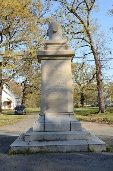
Spectacular! Maybe someday I can take on a project like this, but in the meantime, I'm just going to enjoy the work vicariously. Your construction of the boiler system reminds me of an incident aboard USS Mound City, a sister ship to Cairo, during an expedition up the White River in Arkansas. The goal was to knock out a river battery at St. Charles, AR. Here's how that went. "As the Mound City moved forward...she fired several shells, but the Confederates stayed quiet, well hidden in the trees and brush. AT 8:45 AM [June 17, 1862], Colonel Graham Fitch and his 46th Indiana were landed and proceeded up the left bank toward the bluff. Soon his skirmishers encountered Williams' men, and with the first Confederate positions pinpointed, the gunboarts opens with a heavy fire of grape and canister that forced Williams and his men to fall back. Fry's light guns now joined the fight and at 10 AM, Dunnington opened up with his battery. Kilty soon silenced Fry's lower battery and moved the Mound City to within two hundred yards of Dunnington's battery. By this time Fitch's men were in position to storm the meager defenses, but Kilty told him not to risk his men; the Mound City would silence the guns. As the Mound City passed the lower battery, Kilty ordered his men below to avoid the small arms fire from Confederate sharpshooters. Suddenly "there was a crack,' a rushing sound, and an awful crash." Commander KIlty had just opened the trapdoor to the gun deck and was shouting orders when a blast of live steam came rushing into the pilothouse. Kilty was thrown back and the pilot, blinded by the steam, fell through the opening to the steam-filled gun deck. One of Dunnington's shots from the rifled 32-pounder had penetrated the port casemate, tearing through four men; passed through the steam drum and heater; then lodged in the seerage cupboard. As steam enveloped the Mound City, men frantically tried to escape by jumping overboard. Rebel sharpshooters on the banks began firing at the scalded men desperately trying to save themselves. ... The Mound City's plight brought a quick repsones from Colonel Fitch and the other gunboats. Fitch ordered the gunboats to cease fire, then charged the enemy positions. Lt. George M. Blodgett, in the meantime, brought the Conestoga alongside and secured a line to the Mound City's stern, then began to tow her downriver. As Fitch's men overran the Southerners, cutters from the other boats were lowered to rescue as many survivors as possible. The Mound City was towed downriver about a mile and secured to the bank, after which the Conestoga's bluejackets entered the casemate. They were shocked at what they found. The scene was described by the correspondent from the Cincinnati Commercial: Here lay the bodies of some 20 men scalded to death, others with their mangled bodies severed asunder by the fatal shot. The gun deck was literally strewn with from 75 to 80 others, who, being badly scalded and horribly disfigured, were tearing off their clothing and long strings of bleeding flesh hangling from their finger ends, hands, arms, and lacerated bodies, and with eyes burnt out and closed, crying out for "Help, help -- water, give me water, water -- save me. Oh God, save me, save me. Oh! kill me, shoot me. Oh, do end my misery. Doctor will I live? Tell my wife how I died," and numerous pitiful exclamations and pathetic appeals of this character. The features of all were wonderfully distorted. Many could not be recognized by their most intimate friends." Every time I've visited USS Cairo and looked at that steam drum and the single steam outlet in the center of it, which branches to the two engines, I think of USS Mound City and the living hell aboard her when that shot penetrated the steam drum and let loose 140 psig (9.7 bar, 361°F, 183°C) steam into that confined space, with nowhere to run. It's just horrifying. That's what combat was like in these western river gunboats and they saw a lot of it. Mound City wasn't taken out of action by this. She was back in action at Vicksburg, Grand Gulf and the Red River Expedition in May 1864. She was sold in November 1865 and broken up in 1866. That account, by the way, is in another really great book, Ironclad Captain: Seth Ledyard Phelps and the U.S. Navy, 1841 - 1864 by Jay Slagle (Kent State University Press, 1996). And if you're ever in St. Charles, AR, you can see a monument to the action. According to the all-knowing Wikipedia, "its inscriptions commemorate the 148 Union soldiers who died in the explosion of the USS Mound City, caused by what is sometimes described as the single deadliest shot fired in the entire Civil War. Inscriptions on another side memorialize the smaller number of Confederate dead in the engagement. The monument was placed in 1919 through the efforts of a relative of William Hickman Harte, the master on board the Mound City who died in the explosion, and is one of the few memorials placed in a Confederate state by a northerner in commemoration of both Union and Confederate war dead." Dan
-
Brian: I've with everyone else on this. Thanks for the history lesson and your passion for the subject will keep you interested through a long build. One of these days, I'm going to try my hand at Cairo or a similar vessel myself. The naval side of the Civil War is overshadowed by the land war, but there's plenty there for the modeler, lots of technical innovation and experimentation, some of which worked out and some of which didn't. Dan
-
My pleasure. The Vicksburg Campaign is endlessly fascinating. I also recommend Vicksburg is the Key by Terry Winchell. It’s a good read by a terrific historian. I’ve heard him speak a couple of times and, before reading this book, thought his Triumph and Defeat was one of the best overviews of the campaign. I’m also a fan of the U.S Army War College Guide to the Vicksburg campaign, but you’ve really got to be interested in this stuff to get through that one! Dan
-
Grant Wins the War is a great, and underrated, book about the Vicksburg campaign. It's one of my favorites ... and I've read a lot of them. Another one that I highly recommend is Occupied Vicksburg by Bradley R. Clampitt. I could not put this book down. I'd often wondered what it was like for the civilians of Vicksburg. Before the war, Warren County, MS, was the wealthiest county in the country. Think of that! The country was, if not unionist, anti-secession. They knew which side their bread was buttered on. By the end of the war, the slave economy was gone. Their town was destroyed. The cotton economy had collapsed. The railroads had taken a huge bite out of the steamboat trade. The river would change course soon, leaving them landlocked. A quarter of their male, military age population was dead and they got what for their efforts? Nothing. And they were petitioning the Grant administration to get the Army Corps of Engineers to reroute the Yazoo River to give them a riverfront again. If I'd been a citizen of Vicksburg back then, I would have been furious at the people who brought all this about, the firebrands that got everybody worked up about secession! But that's not what happened. The people of Vicksburg were staunchly Confederate and worked for the Confederate cause during the war. During the occupation, they worked against the Union troops constantly, even though it was in their best interest not to. After the war, they still clung to their pro-Confederate positions. This book details all of that, along with the impact on former slaves and how they reacted to the defeat of Pemberton's army, the occupation of Vicksburg and their new-found freedom. It's absolutely fascinating. Dan
-
I hadn't considered this model before, but this build is giving me ideas... Dan
-
What a wonderful model! Are the plans available from The Trireme Trust? I looked at their website and saw some pictures, but didn't see where you could buy a set of plans. And are those the plans you used? I would love to build a model of Olympias. Maybe someday... Dan
-
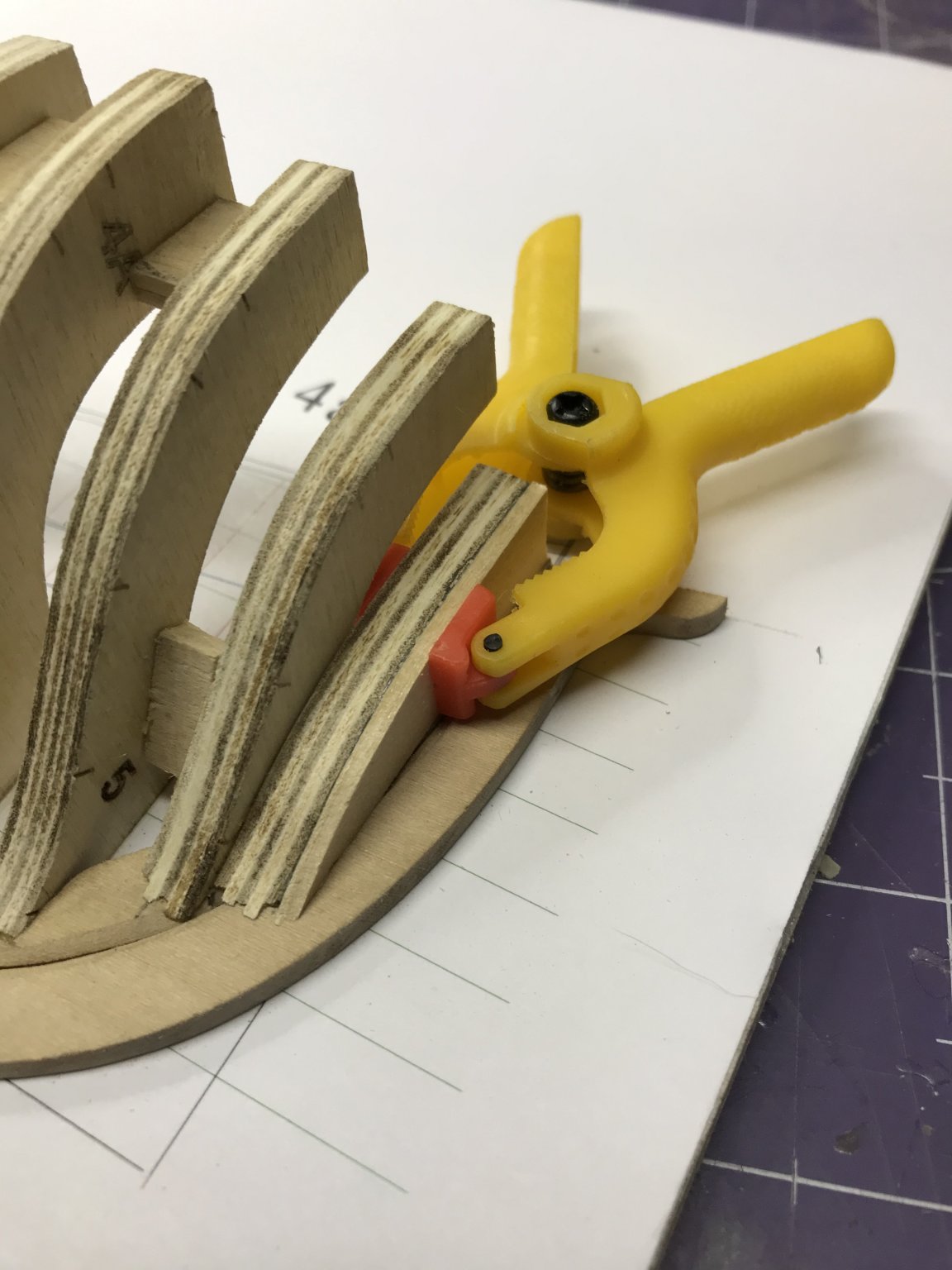
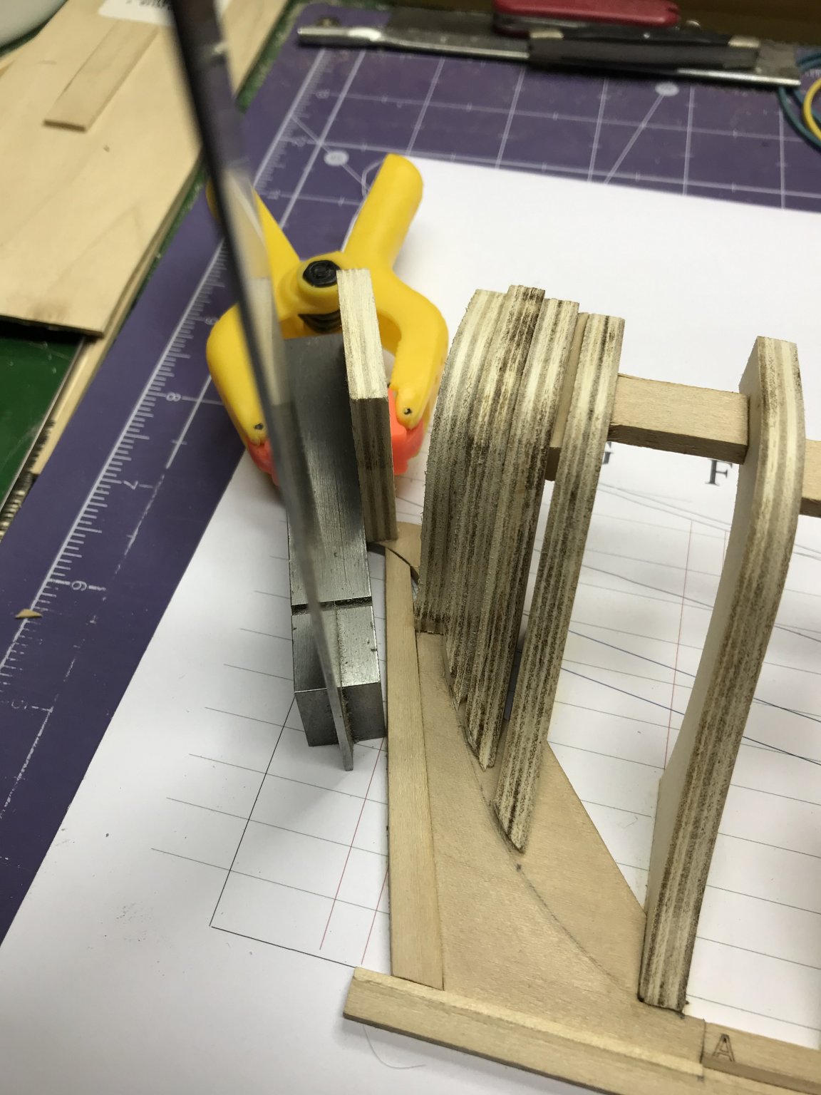
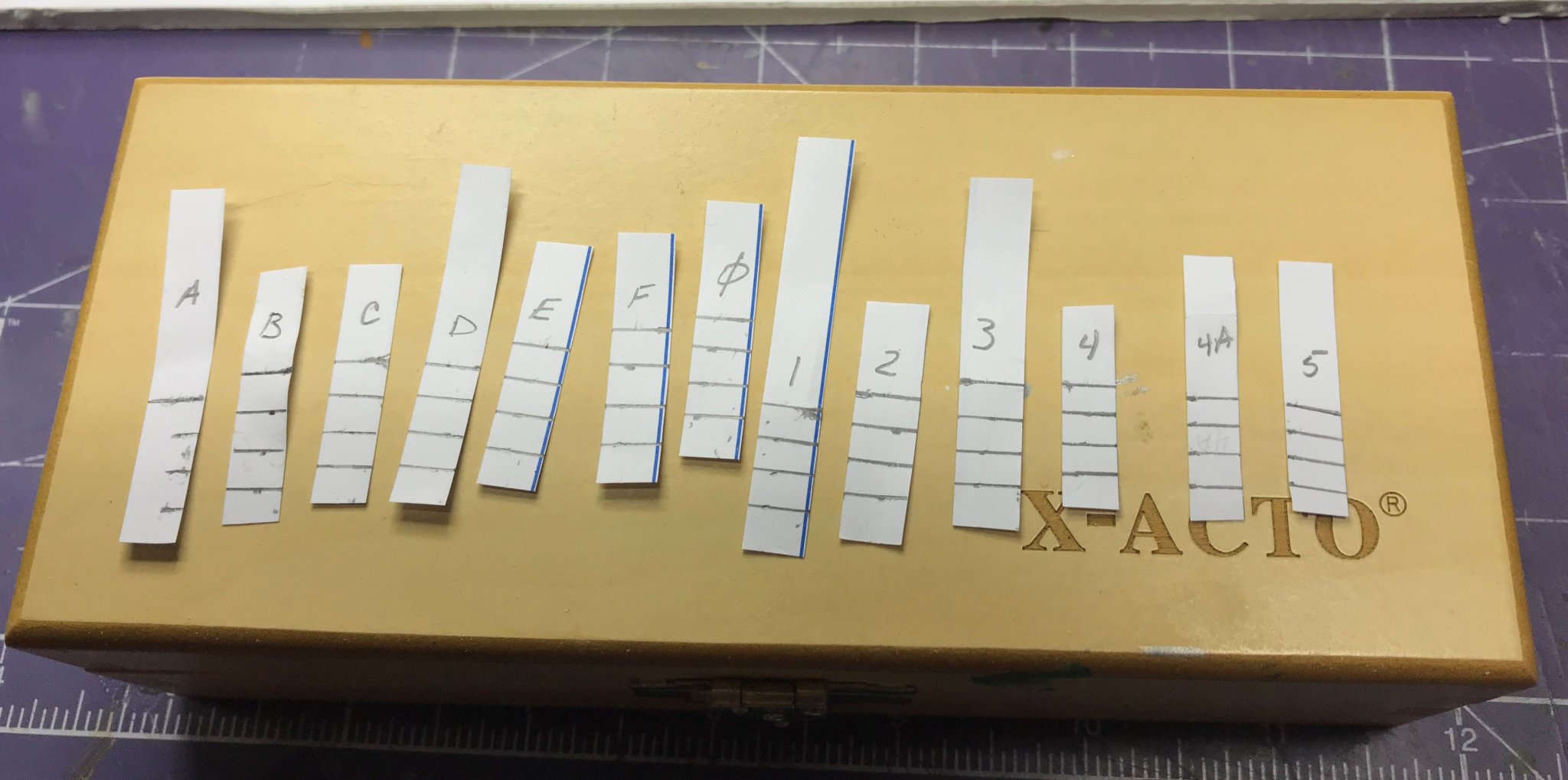
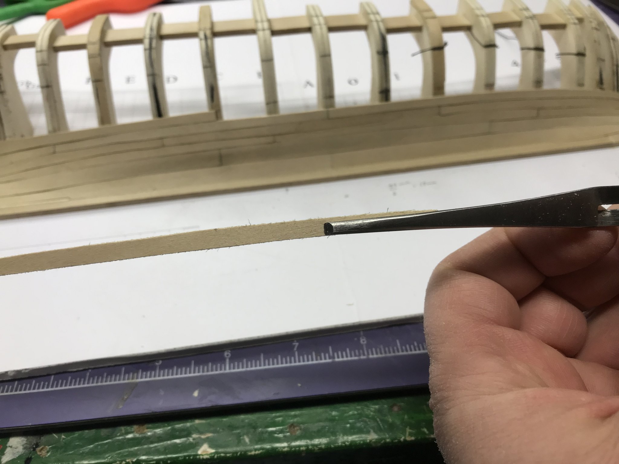
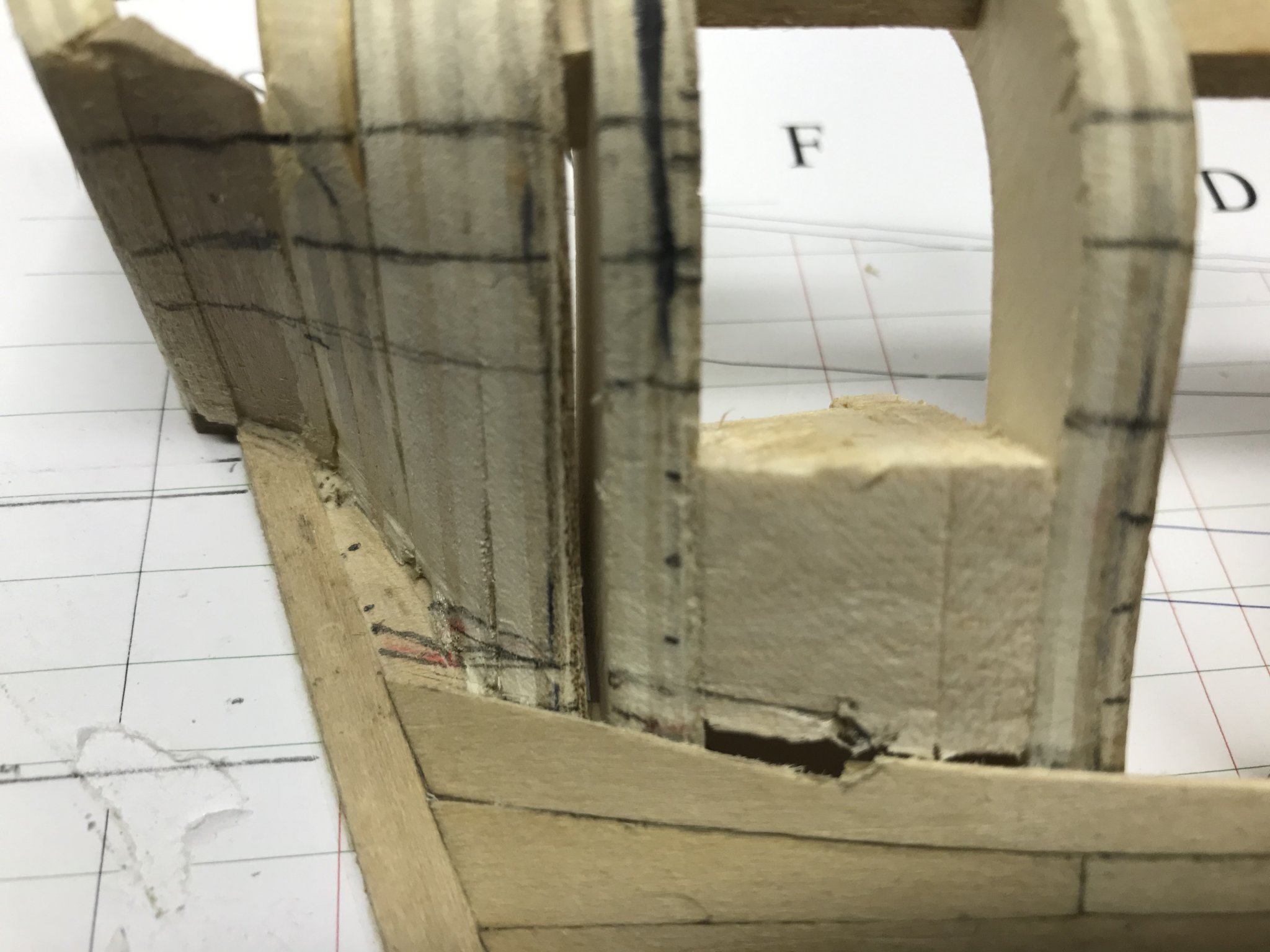
I've been pokey about posting more updates here on MSW. Work has consumed all my time over the past several weeks, so any time I get to spend at the bench is a real luxury. I'm thankful every day for the work, but it is draining. When last I posted, I'd just gotten the planking belts laid out. It took some time to get that right, but it finally did come together. I also took the opportunity to do more fairing. It seems that's a never-quite-ending task, but a ncecessary one to avoid high and low spots. Then I made my tic-strips for each of the frames. Once I made these, I stored them in a little ziplock bag. Don't lose them! You'll need them again and again. Per the instructions I used both methods to lay out the planking. When I used the first method, I thought, "why in the world hadn't I thought of this before." It made a lot of sense and was easy to do. I didn't know it at this point, but, as clever as this method is, I got better results, faster, with the second method. In any event, things went well. Carving and sanding these very narrow planks was a little challenging. I ruined a couple of them doing that, but eventually landed on this method. Just clamp them in a self-locking pliers like this, with a piece of scrap stock on the bottom of them to keep them from moving around, and sand away. I found I could keep them stable, see what I was doing and get a good result doing this. Here's the first belt in place. I think the first plank above the broad strake was too narrow. I discovered that too late, so the next couple of planks are probably a little wider than they should be. That's a live and learn, I think. One great thing about this model is that ever run of planks is better than the one before it. I've really noted an improvement in my skills as I've gone along, which is the purpose of a tutorial like this. The stealer was next. Toni says you'll be lucky to get this right in three tries. I was. I got it right in two. The first was a complete disaster and had to be removed... With that gaping hole in my model -- and, you'll note -- the gap just where the stealer would have to be glued in, I plugged ahead. Toni does say to install a block in between the frames, but what I failed to do was extend that block below the top edge of the plank. I've got plenty of gluing surface where I don't need it in this picture, and none where I do. Removing the first stealer to fix it allowed me to fix this whole issue. And there it is. Since this, I've laid out the second belt of planking and made my next set of tick strips. Lots more planking to do. Dan


-
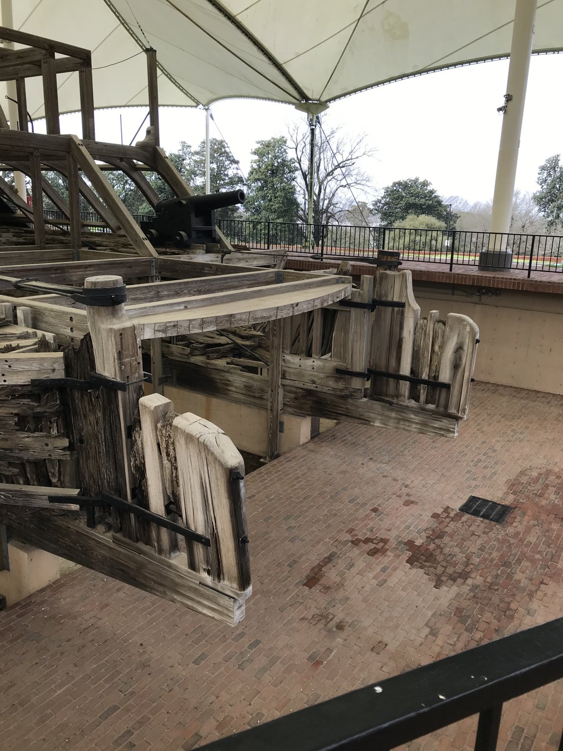
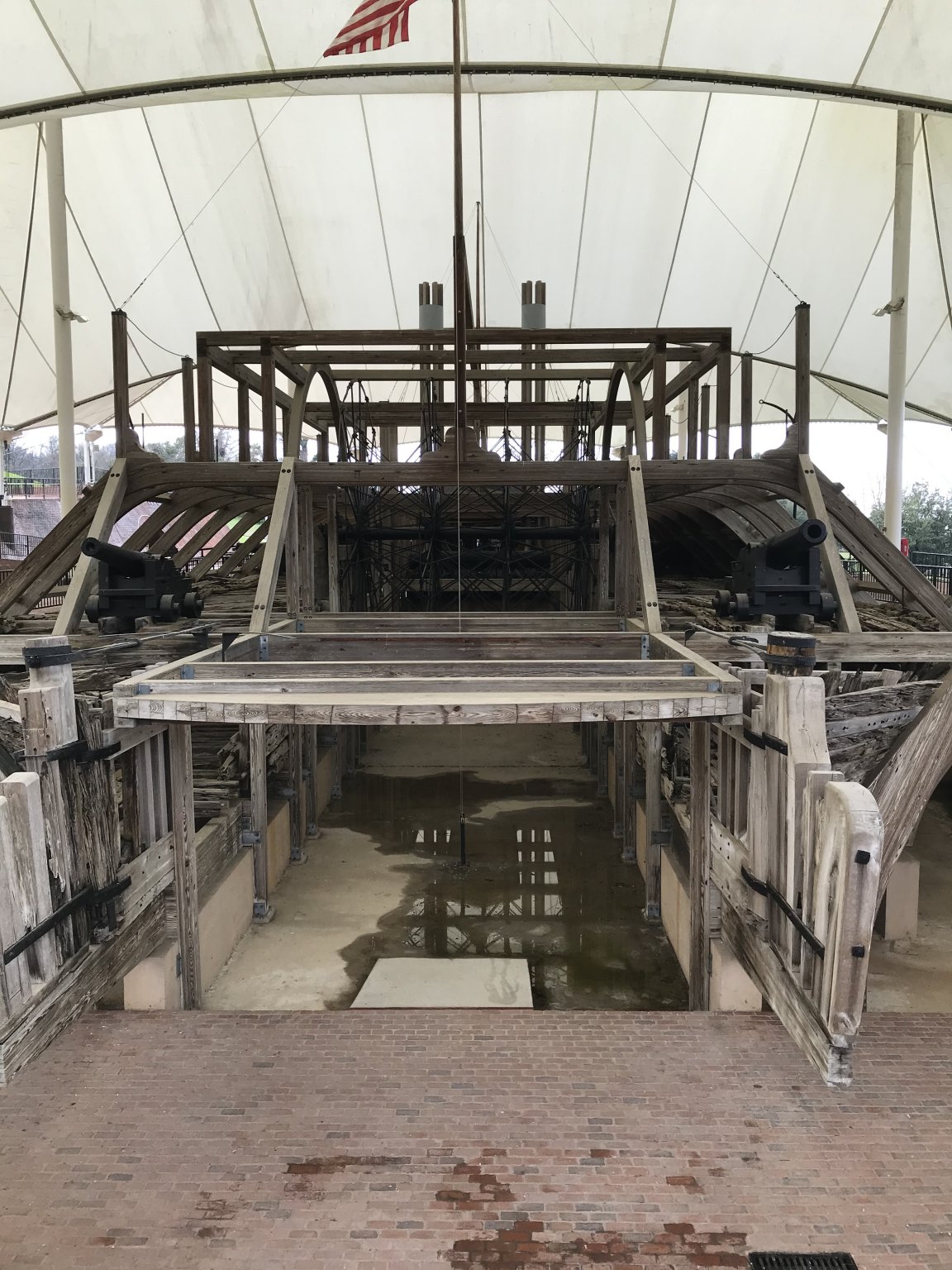
USS Cairo is a fascinating vessel and I'm thrilled to see a build log for her. I visited the Vicksburg NMP for the first time about 20 years ago. I've been back twice since and it's an amazing place. Grant's Vicksburg Campaign was the most complex and successful of the war and the more one learns about it the more amazing it becomes. Outside of professional military circles, I don't think it gets the attention it deserves. Inside military circles, it does. The U.S. Army used the campaign as a model of operational warfare until the first Gulf War when it was replaced in the field manuals with General Schwarzkopf's campaign in Iraq. I'm really looking forward to your build! Dan
- 739 replies
-
- 12
-
-
Hi, Lyle, I'm really enjoying your build log, particularly because you're a little ahead of me. I've got the planking belts laied out now and am ready to start planking. I'm wondering how you handled Toni's direction to: "Make a sketch of the frame plan and planking belts, including the garboard and broad strakes." That's my next step and I was just wondering how sophisticated that sketch has to be. Dan
- 44 replies
-
- 1
-
-
- half hull planking project
- half hull
- (and 2 more)
-
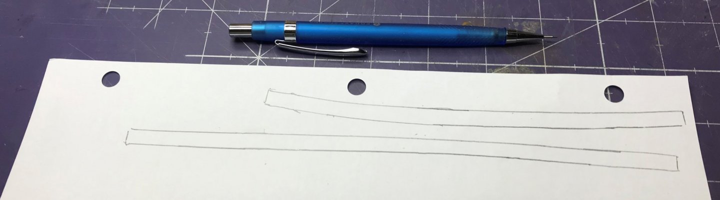
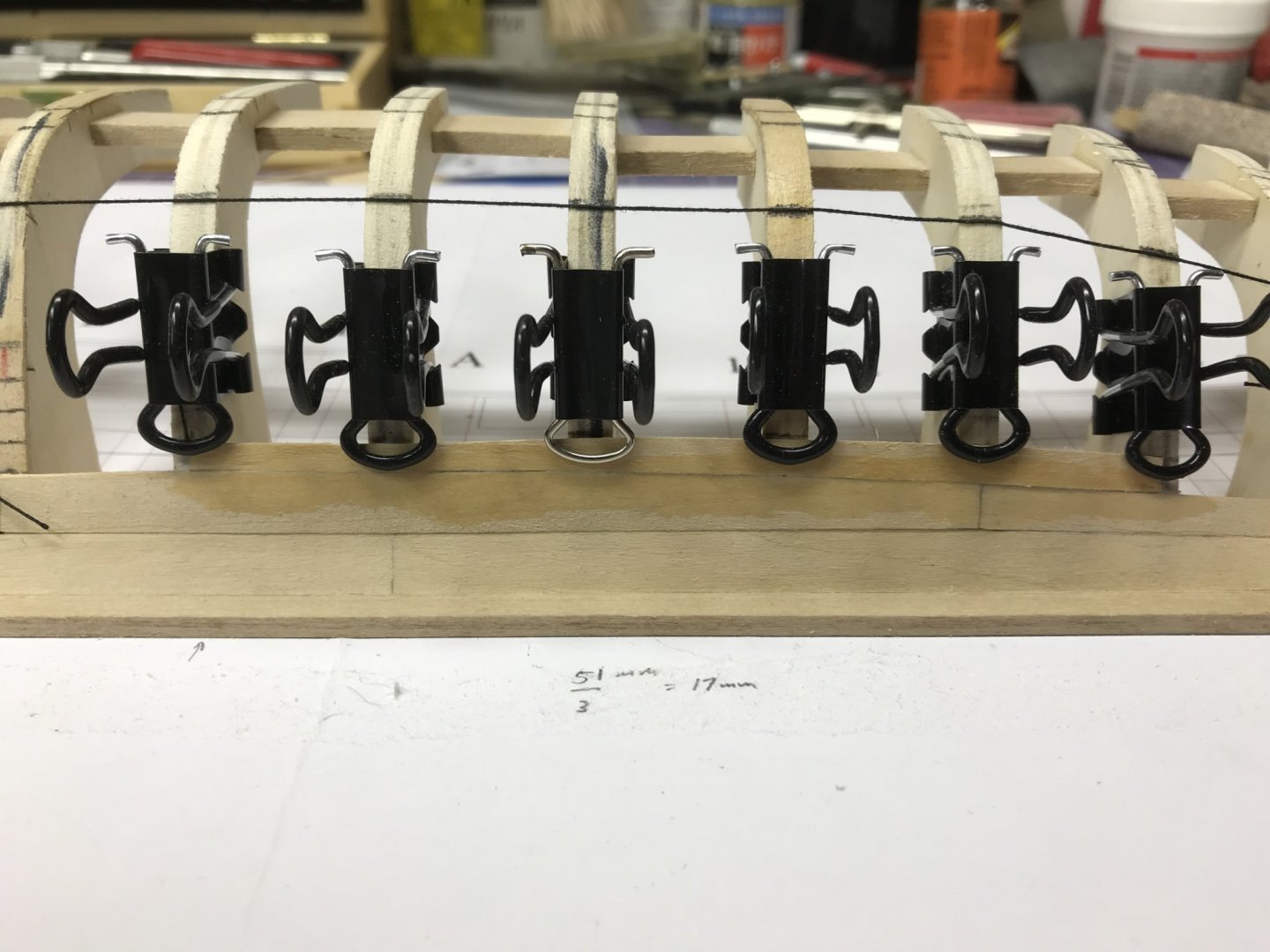
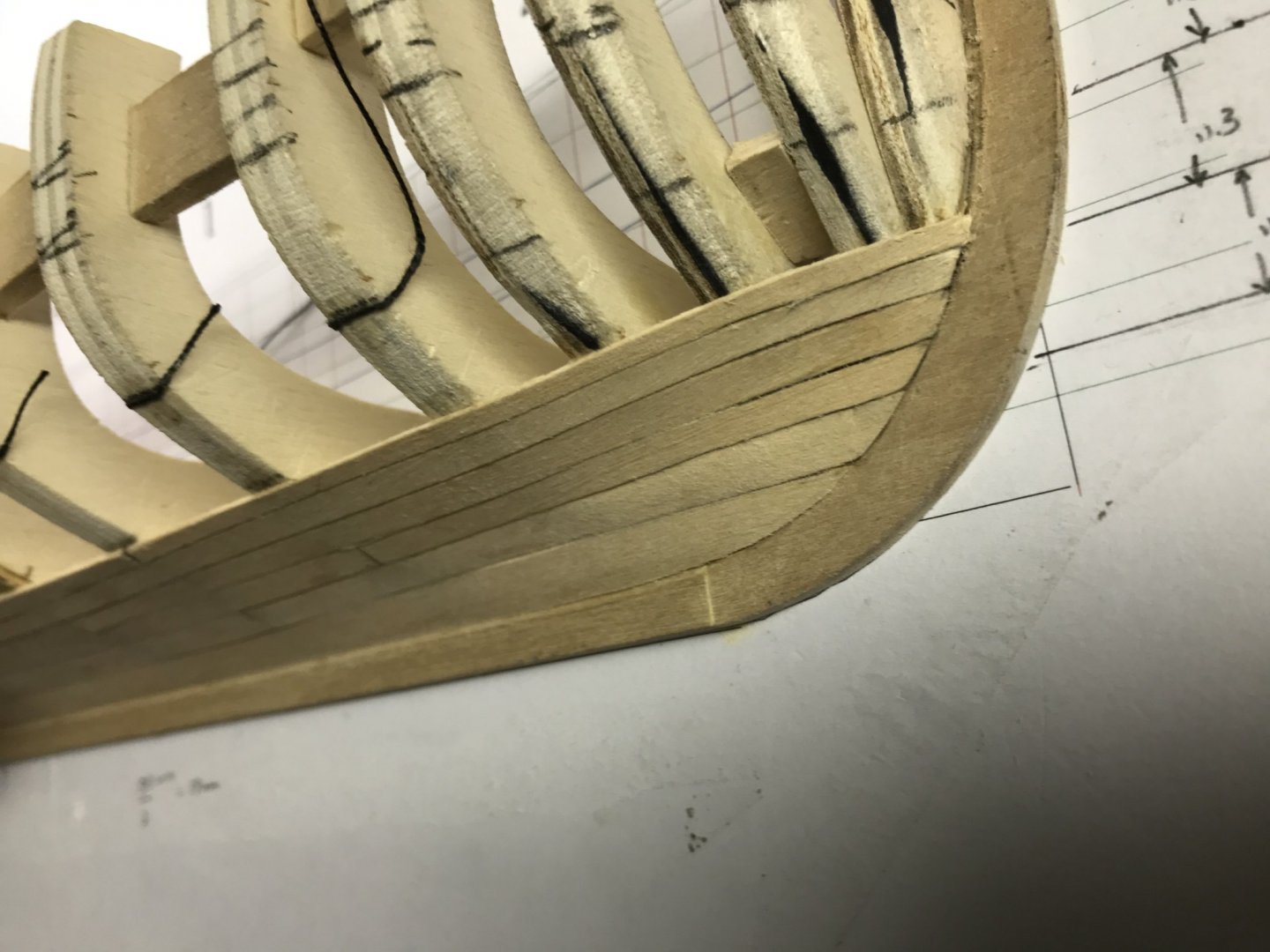
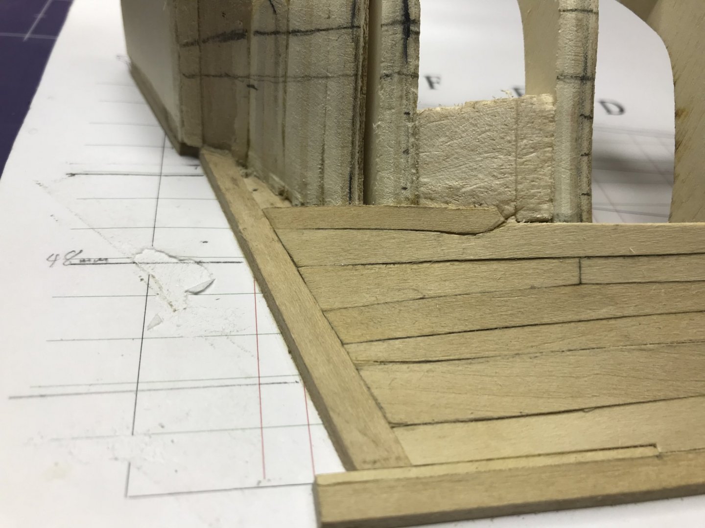
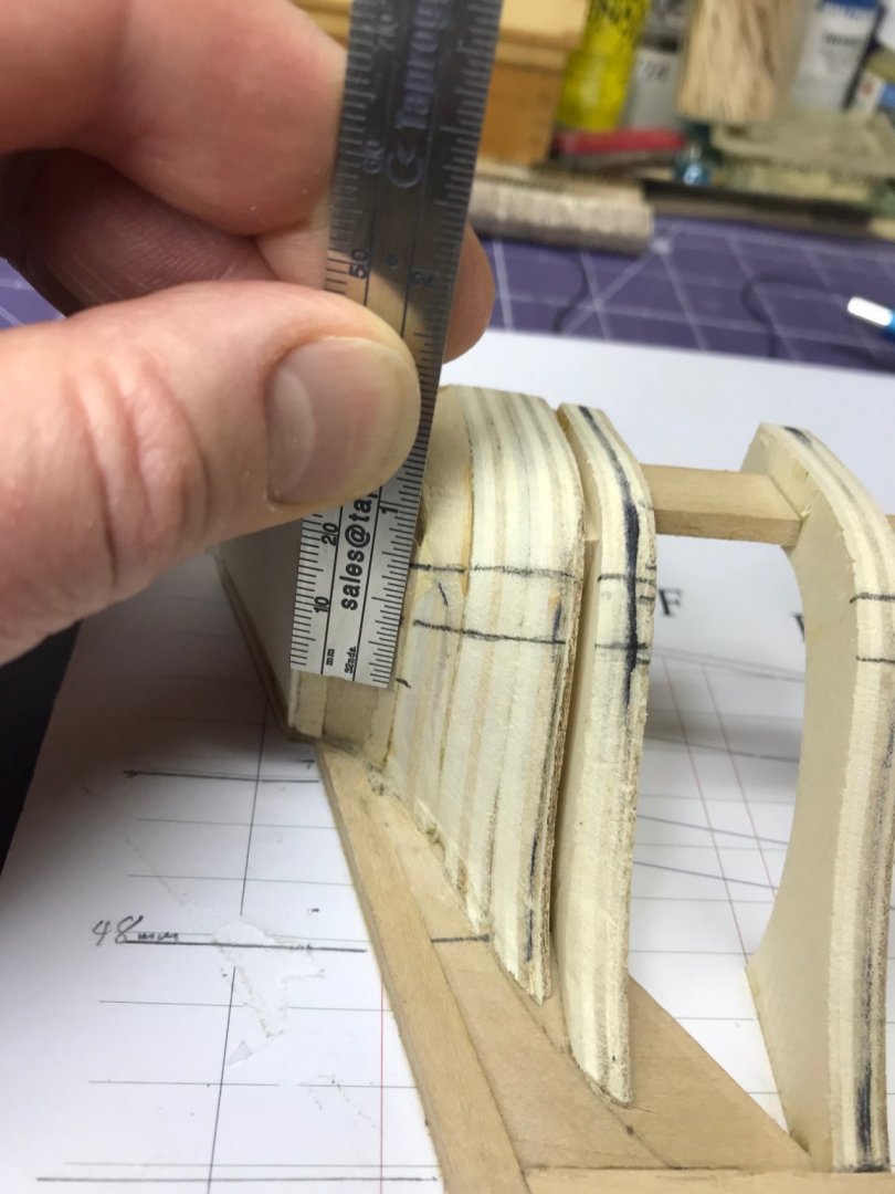
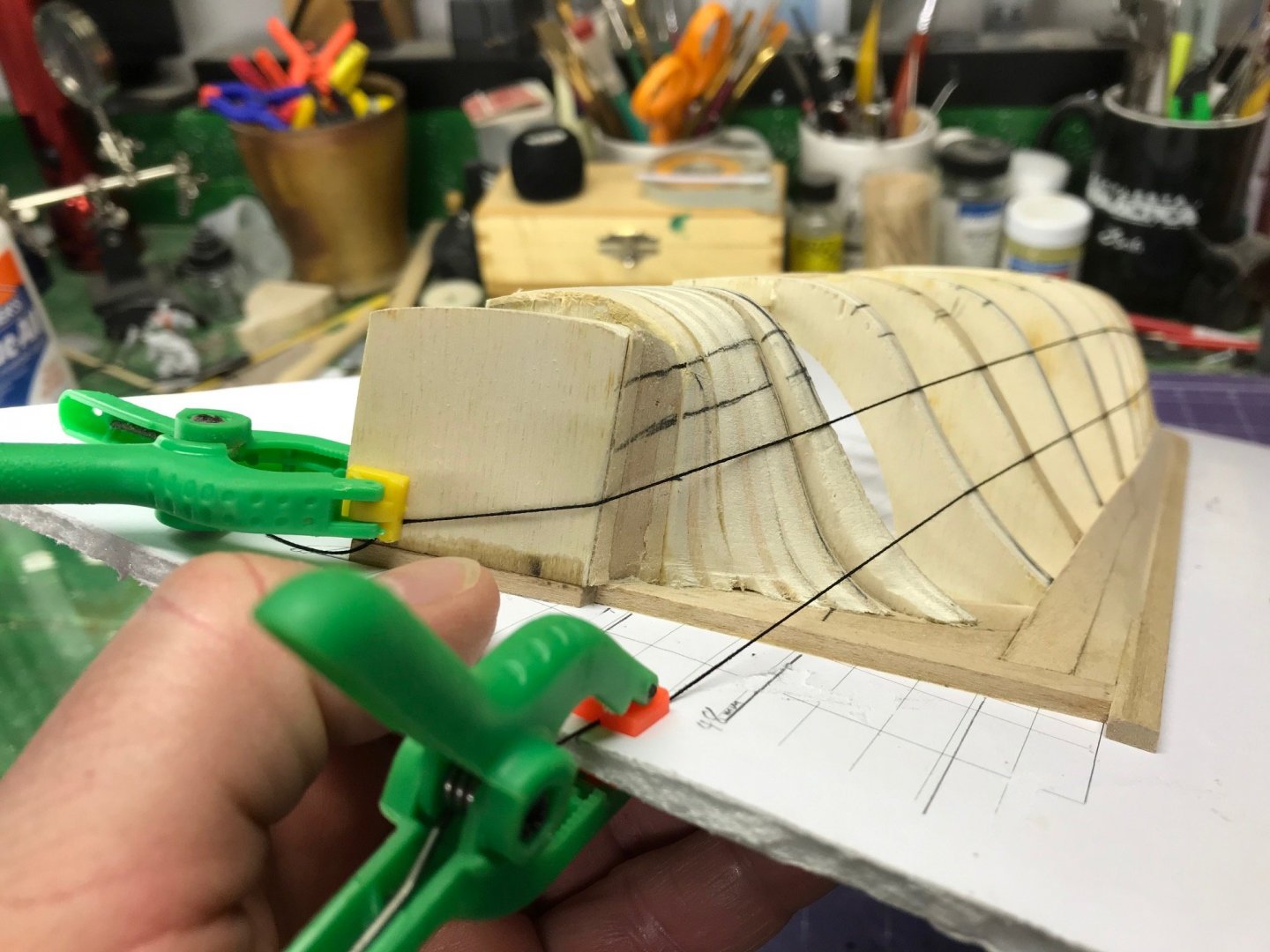
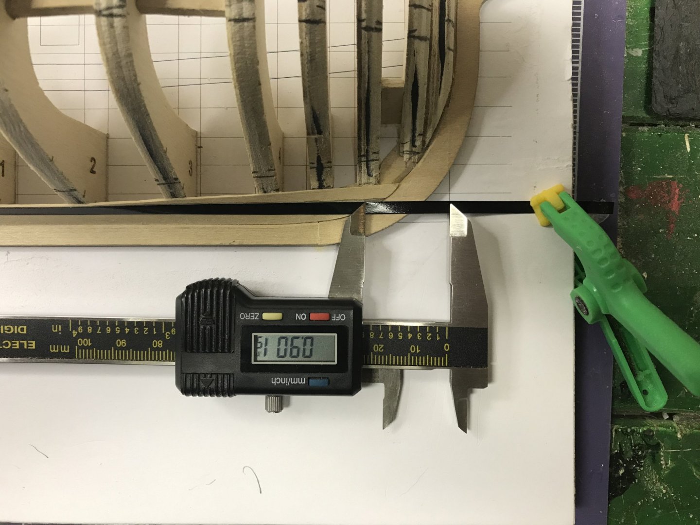
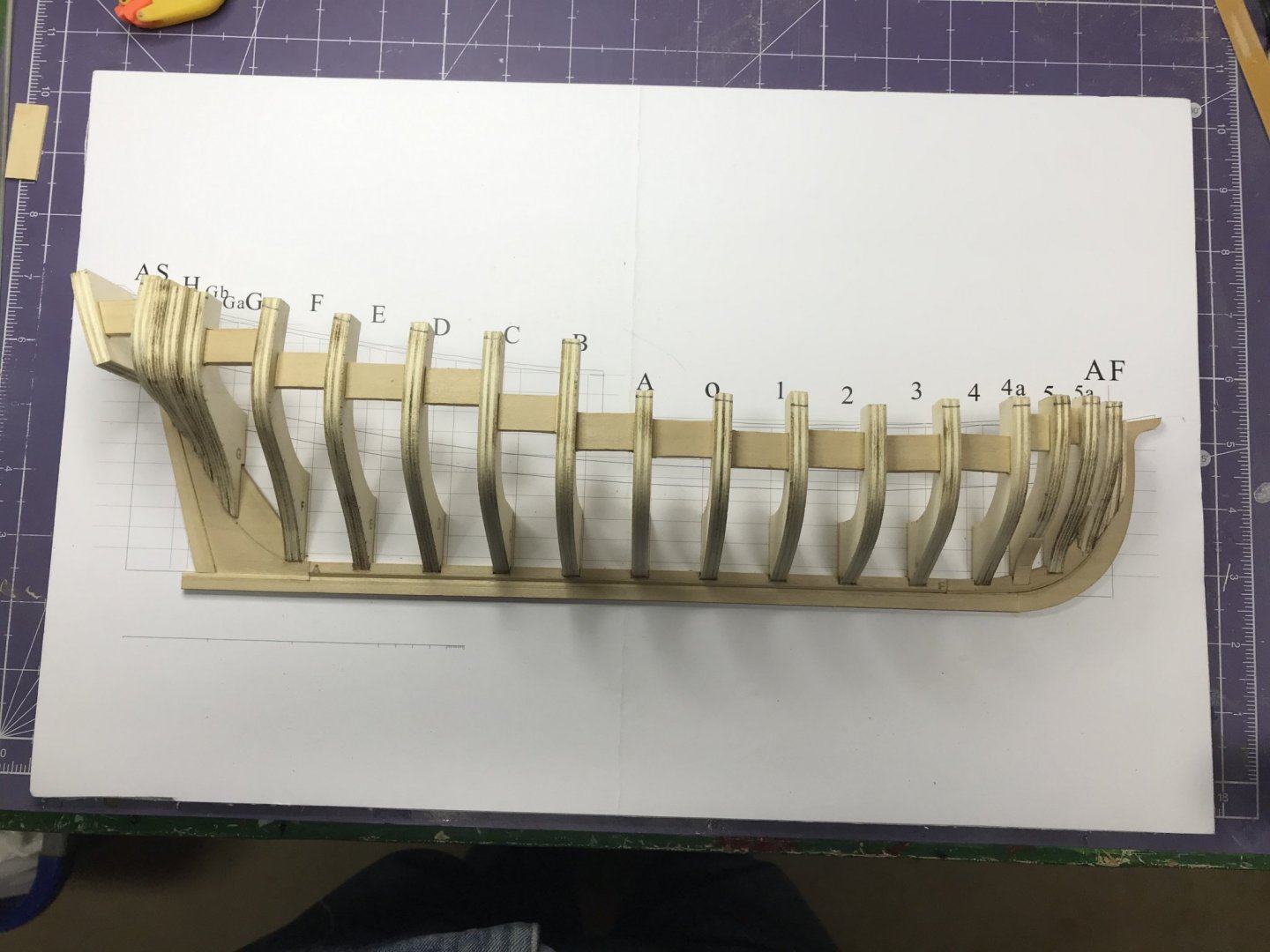
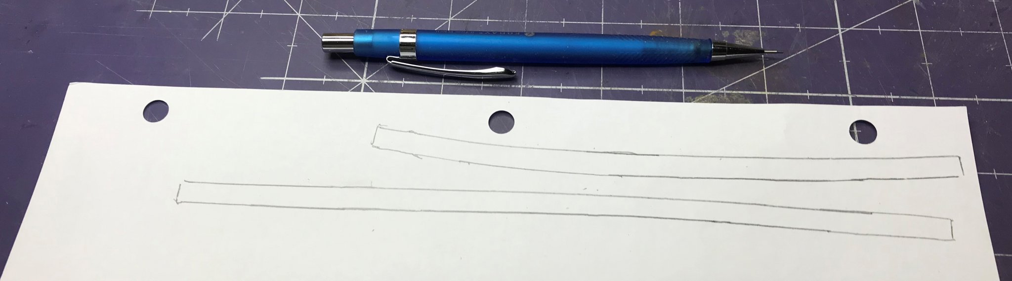
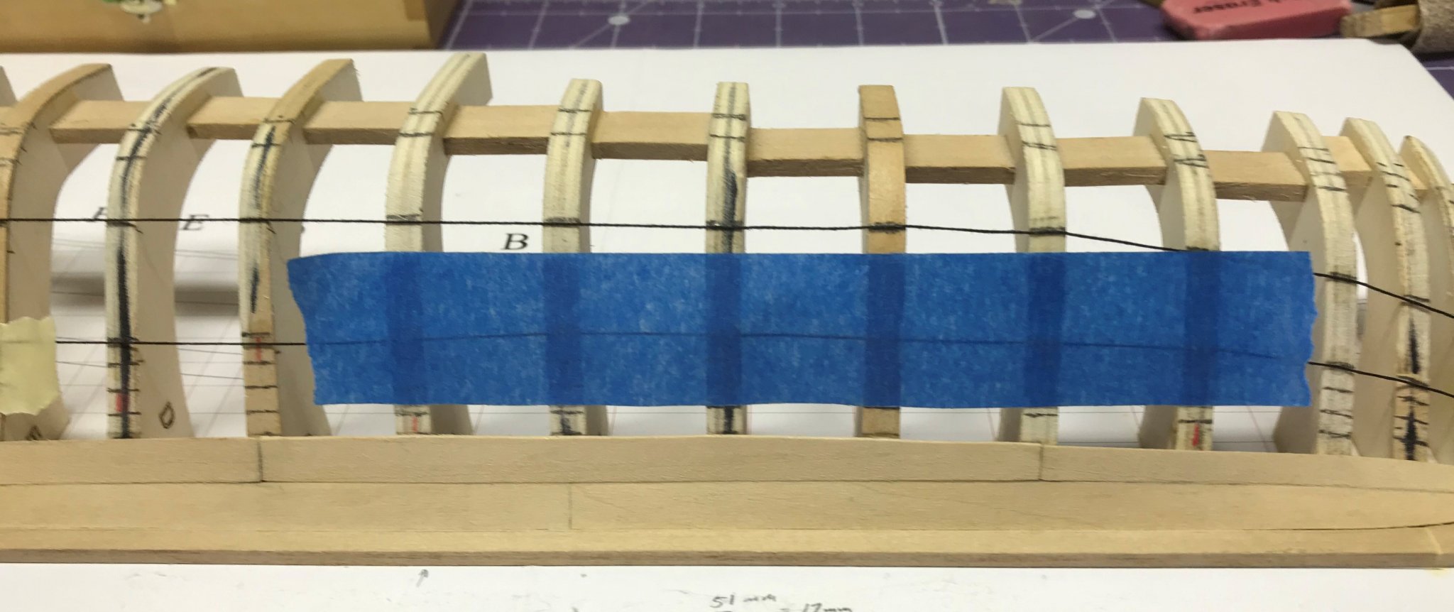
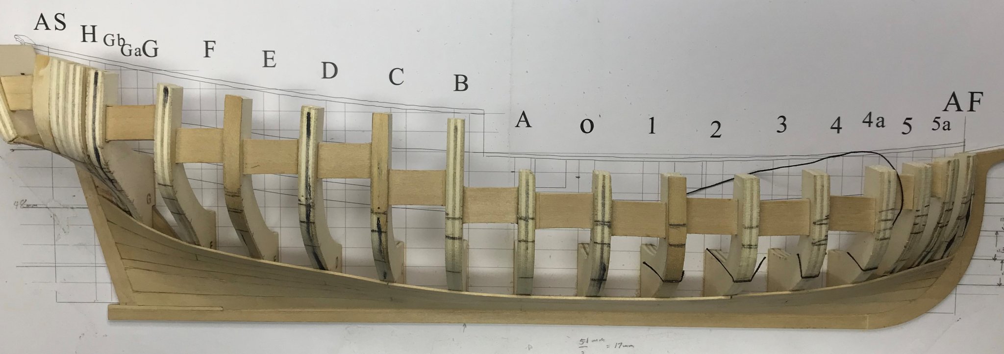
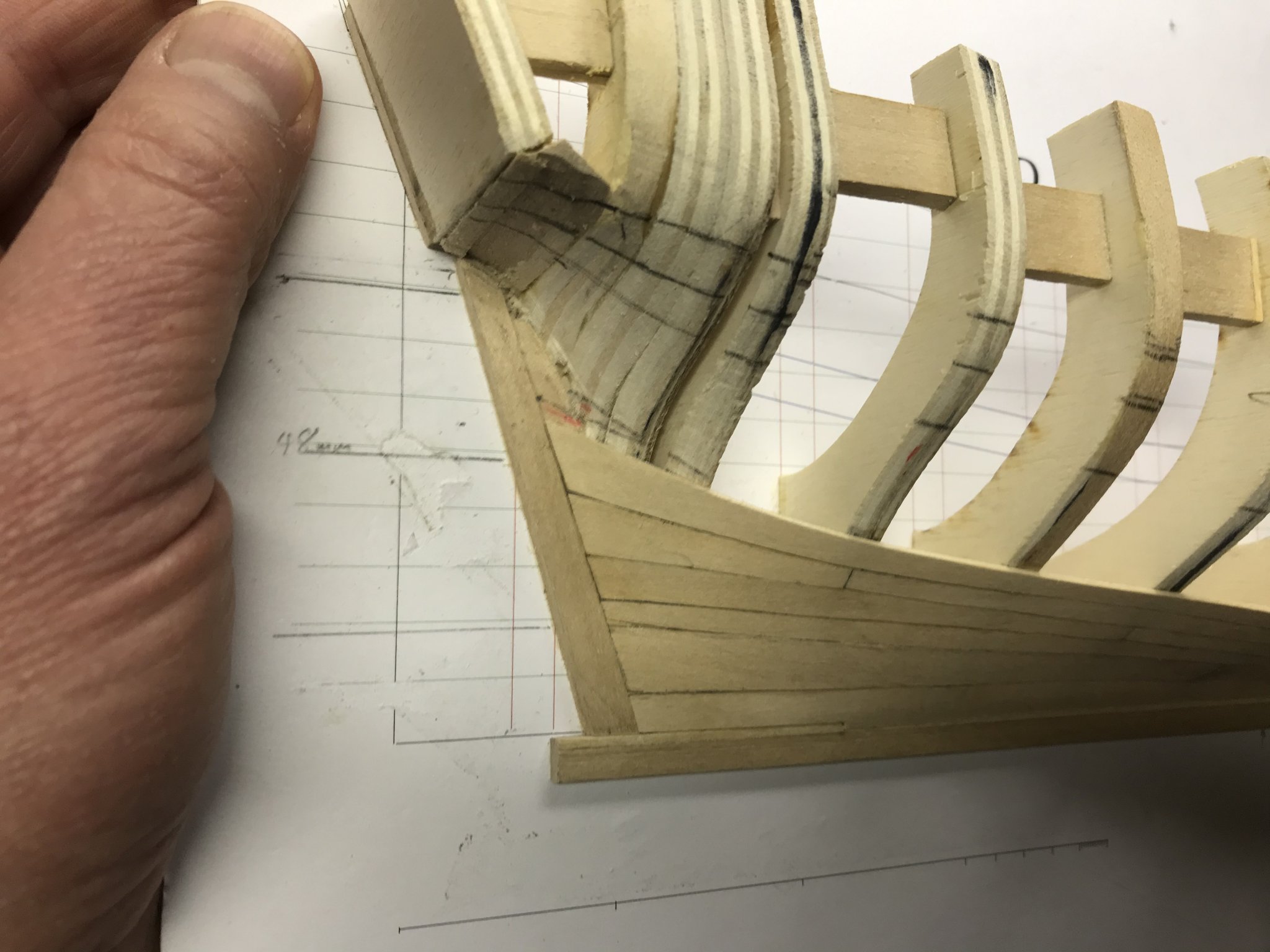
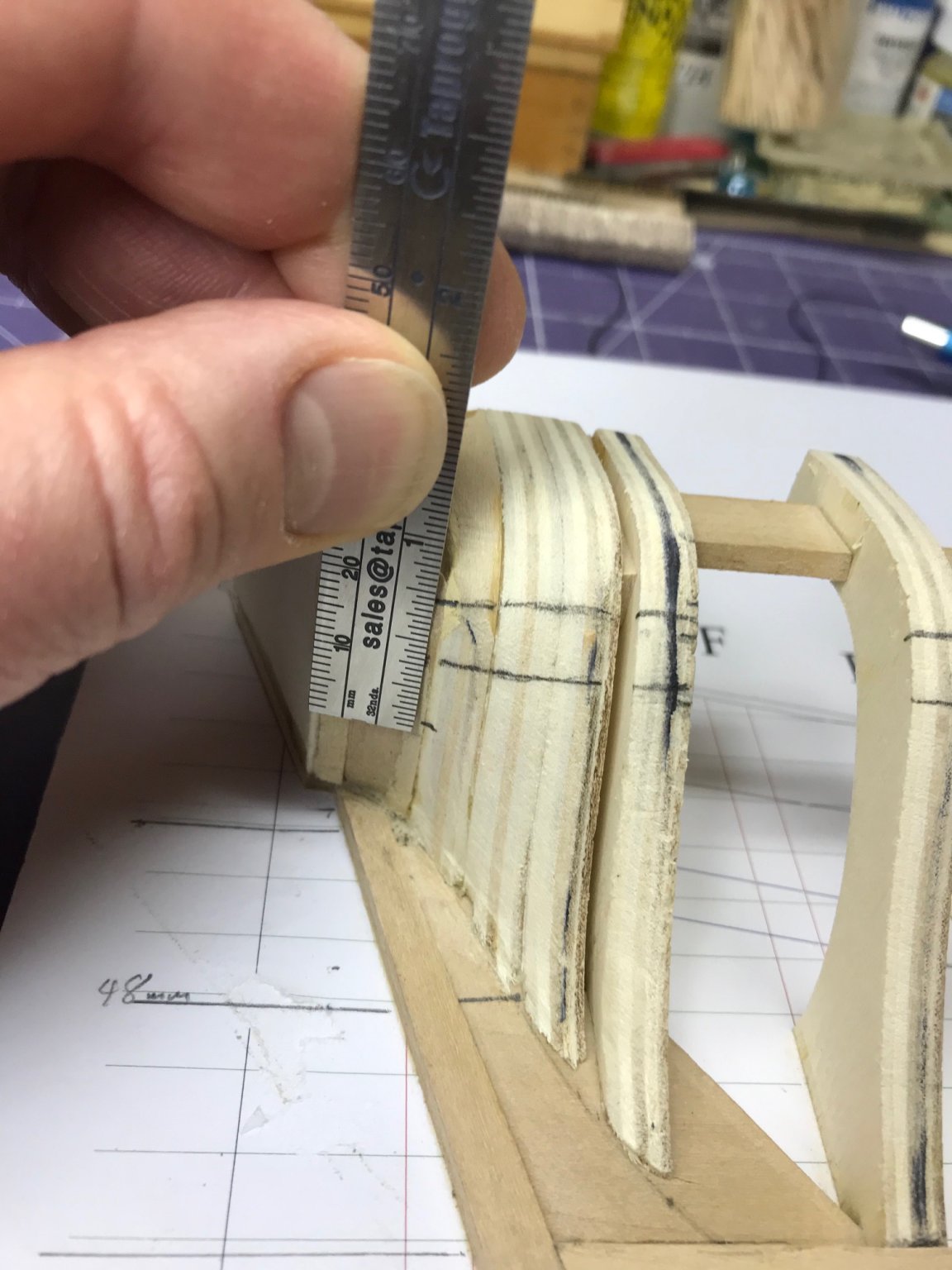
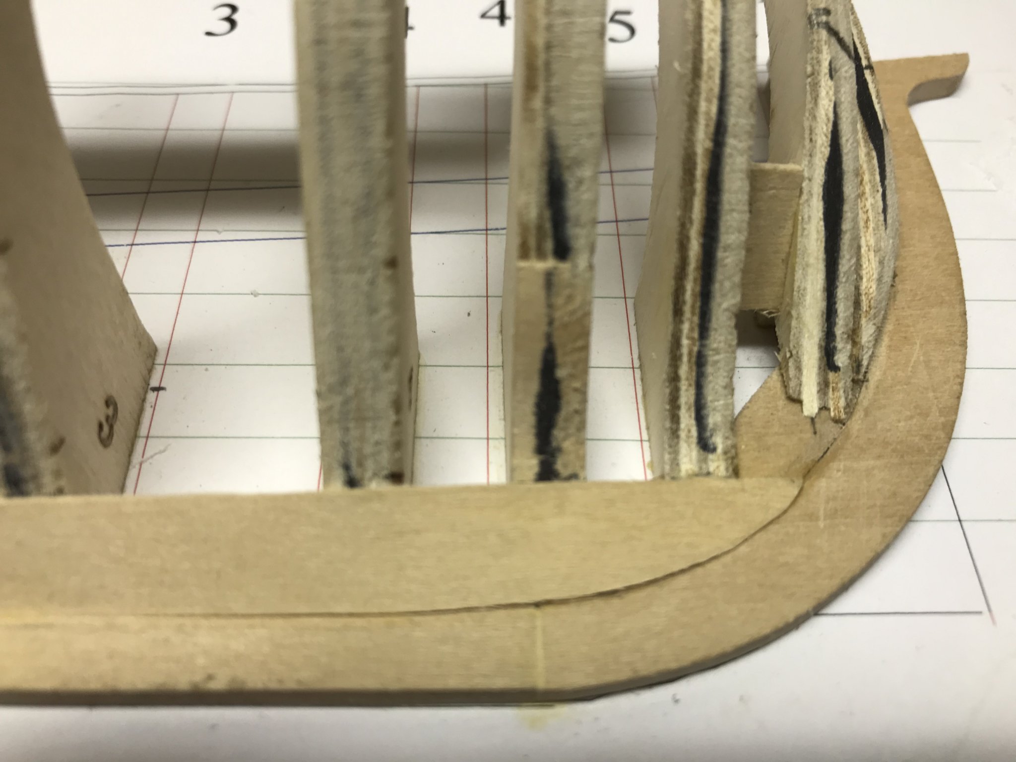
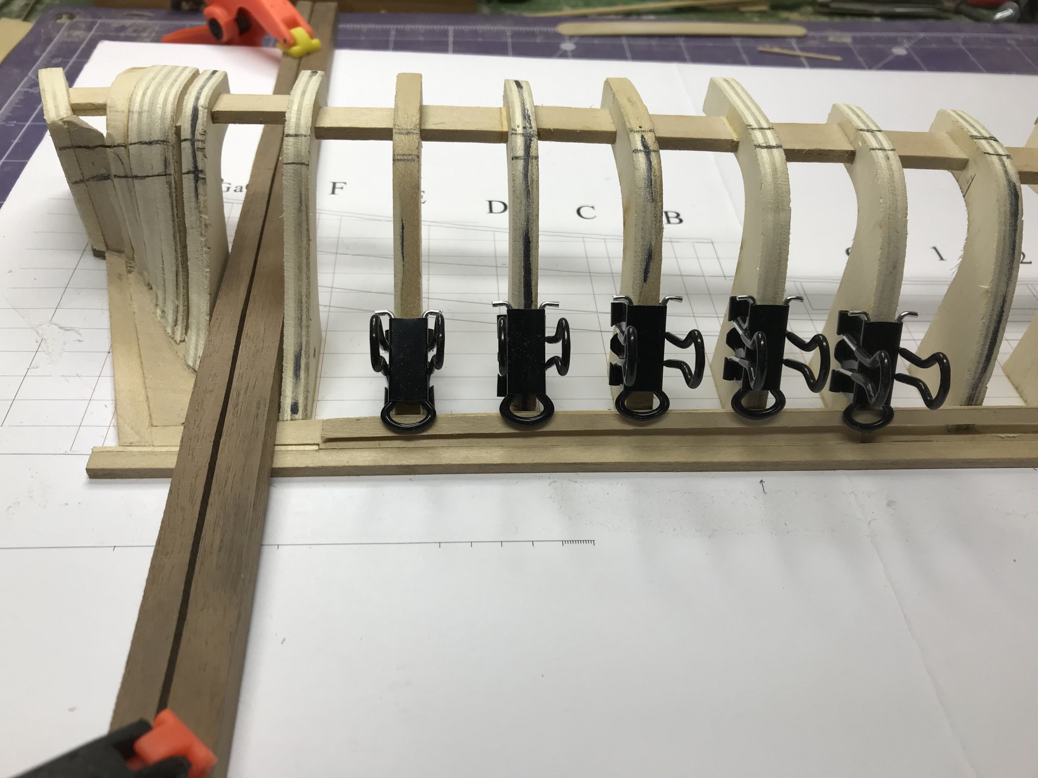
Now on to the first run of planks. I've gotten through about half of this process, but I'm struggling a little. The initial instructions for laying out the planking belts are straightforward. There are three belts of planks, the width of which are determined by the distance from the bottom of the main wale to the top of the broad strake. Simple. Take a piece of paper, mark that distance... Measure... ...in this case 51mm. And then divide by three. That's 17mm. Mark those belts on the dead flat. Easy. For the stem, it's the same process, although the geometry of the stem makes it a little different. I drew a line from the top of the broad strake forward and a line from the bottom of the main wale forward onto the building board. Then I measured that distance, divided by three and then marked those dimensions on the model. In my case, the total distance from the bottom of the main wale to the top of the broad strake is 34 mm, which divides into three belts 11.3mm in width. For the stern? I'm befuddled. As Toni says, "drawing out these belts is more complicated because the planks terminate on both the lower edge of the counter and the sternpost." Okay. Got it. Complicated. Then, in the next paragraph: "The width of the lower planking belt at the sternpost is 4.5 (four regular planks and half a stealer) times the extreme width of 11" or 49.5". In 1/48 scale, this is just over an inch. Mark this at the sternpost." Okay. I can do that. So that defines the border between the lower and middle belts. Now I need to mark the border between the upper and middle belt. "Measure inboard along the lower edge of the counter the width of four planks 0.75" (4 planks x 9" plank width / 48 scale)." This had me baffled yesterday, but, as is my wont, I've let that thought marinate a little and here's what I came up with. I've been thinking all along that the orientation of the planking belts is largely vertical, with some athwartships dimensionality to conform to the shape of the hull. But in the case of marking out the border between the upper and middle planking belts, the orientation is largely athwartships. So, "measure inboard along the lower edge of the counter" looks like this: So ther planking belts will look something like this from the stern. (I'm not taking any more pictures for now because there's a lot of adjustment that needs to be made to get these things right, as Toni points out in the instructions.) Dan
.thumb.JPG.69dce0f1c2bc6699321aa8f379baec16.JPG)
.thumb.JPG.a58c0374e9653c5c62002f7c893d9e7c.JPG)
.thumb.JPG.966c3537c2e159194df0498a3fd5d4e3.JPG)
-
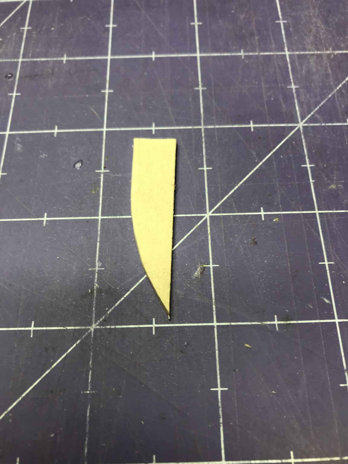
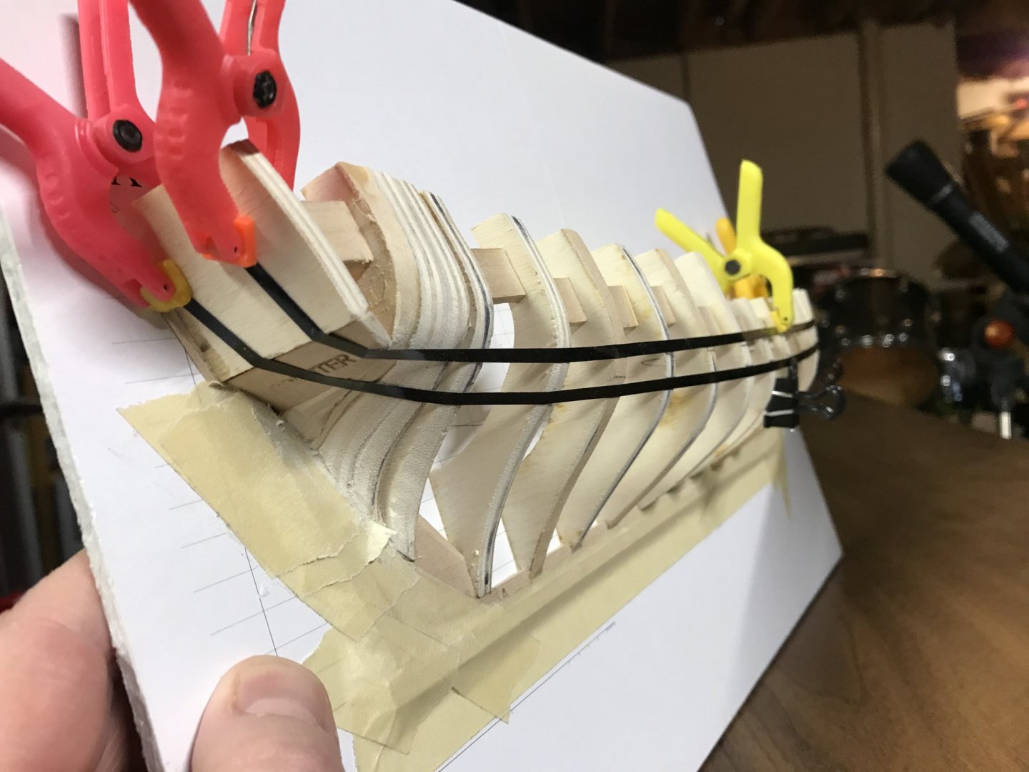
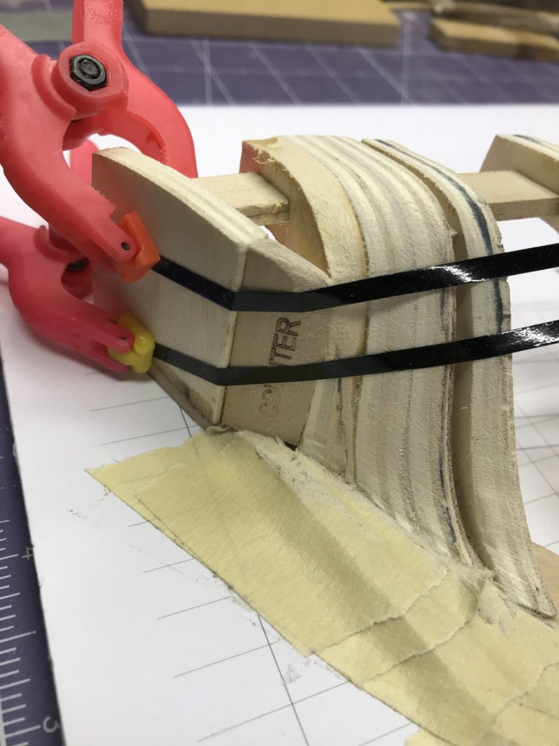
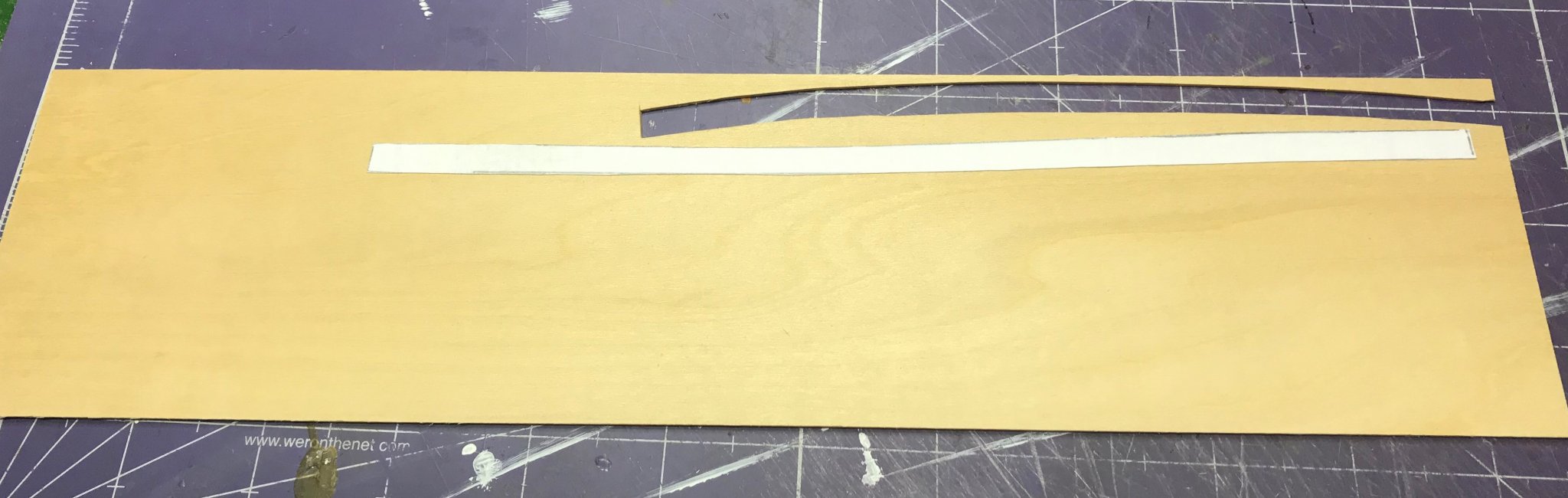
Thank you, Gentlemen. I'm glad you're enjoying the build log. To the question about how I'm going to mount it, I would like to do it in the traditional half hull manner, on a wood backplate. I'm concerned about the appearance of the top of the model though. I don't want it to look like a construction site, which would happen if I left the tops of the frames exposed. I'll need to do some thinking about this as the project progresses. With the garboard strake in place, I moved on to the broad strake. This plank took more work than the garboard strake. I made three aft planks before getting one that I could install. The fundamental problem is the amount of twist in these planks. Of the three, the midships plank is the easiest to lay-out and install because there's very little twist in it. Not only was it difficult to lay out the forward and aft planks with the Tamiya tape, but it was also hard to test fit them to make sure they would fit. For the forward plank, Toni's instructions say, "mark the sternpost, dead flat frame and bow for the top of the strake and run a piece of tape to represent the top of the planking. Again, be careful not to let the fore end of the planking run too high up the stem." For the garboard -- and as I started laying out the broad strake -- I layed the tape out and then marked every frame, measuring all along, but with the instruction to not "let the fore end of the planking run too high up the stem," I came to the conclusions that this is a much less rigorous, analytical process than I had thought. It comes down to mark three spots and then eyeball it in. Once I'd made that leap, layout got easier. Now to that torsion issue, I've built with basswood before and it bends really nicely -- it even edge-bends nicely -- when simply wetted down with some warm water. The heat of your hands working it is all that's needed, no fancy plank benders or anything. After trying to horse the plank in place, I decided to just do that. It's not mentioned anywhere in the instructions, but it certainly helped me. I clamped the plank in place and let it dry. When it was dry, I removed it, applied glue and set it in place without all kinds of force. Toni does mention, earlier in the instructions, to be careful of putting dents in the wood. That's easy to do and I did it. I've since been working that little dent out by applying some water and letting the grain expand. You can see it in the second photo below. The center plank, because there isn't much twist in it, is easy to lay out and install. The after one, where there's the most twist, I found hard to lay out. It took me three tries with the third time the charm. Same procedure though. Lay it out with the Tamiya tape and cut the plank. Wet it to make it more pliable and clamp it in place. Remove it when dry -- and here's the tricky part -- sand, fit, sand, fit, sand, fit, repeat as necessary until it's right. In the end, I'm very happy with how that plank looks and the run of the broad strake, but it was more work than I anticipated. You can see in this photo the amount of twist in that plank. Here it is clamped in place. And here's the finished result. Dan
.thumb.JPG.3d5a4bfa7a3b3a4be2b13ef4b94000f1.JPG)
.thumb.JPG.27d134aa63de0db1e8633873854c13bc.JPG)
.thumb.JPG.f5ad7742ae6792ba4e77e30d79c92f7e.JPG)
.thumb.JPG.0db77ab874bd7258b2a1b5b8294a8a6b.JPG)
-
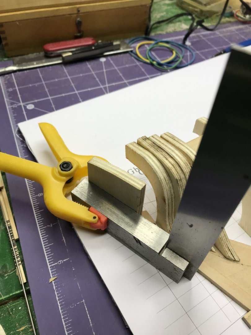
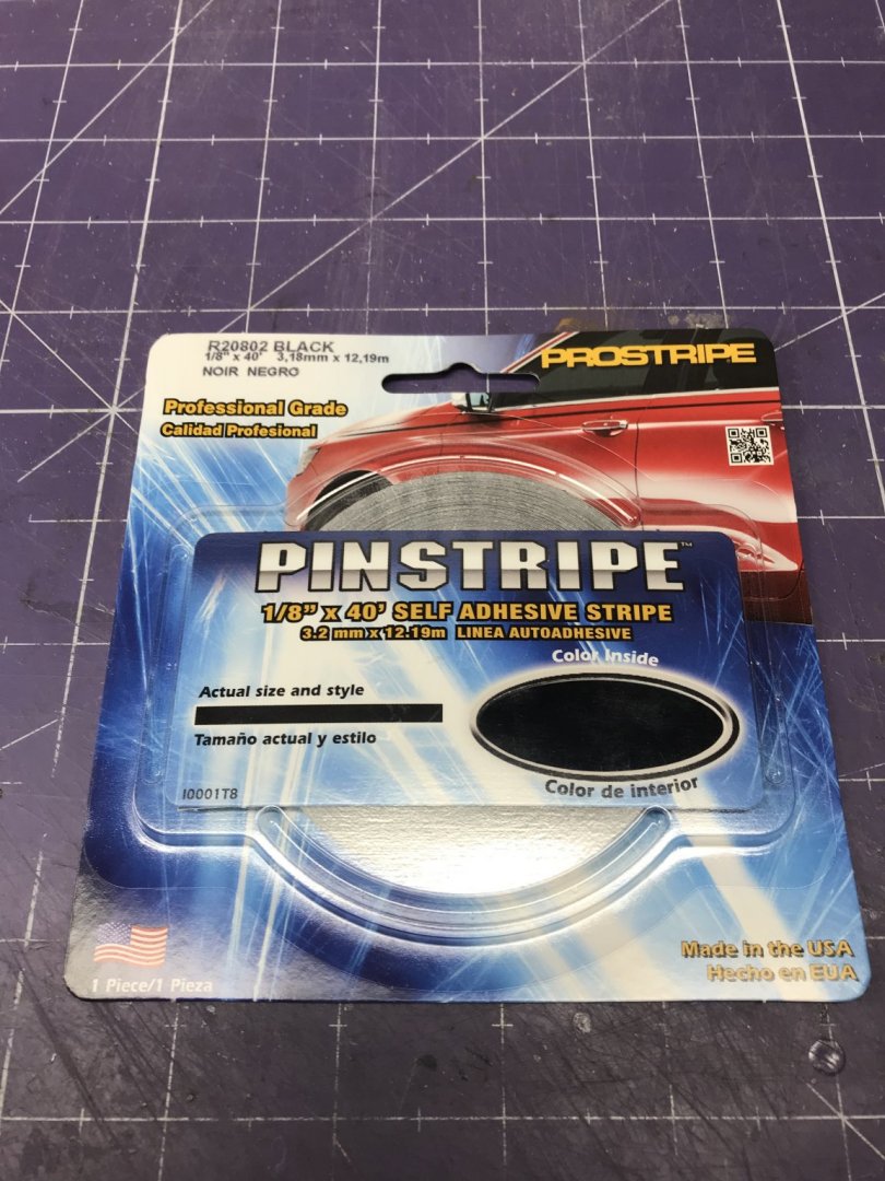
Well, two steps forward, one step back. On Friday night, I got this from Kurt Van Dahm, President of our club, the Nautical Research and Model Ship Society of Chicago and NRG Director: "A good indication that the Garboard plank is correct is to look at it at 90 deg to the keel piece and it should be a straight line fore to aft w/o the bow end rising. It looks good from the head on view down the length." So, I decided to check and, by that measure, my garboard strake needs work. You can see that it does rise up at the forward end. I've used Titebond on this model, which can be removed with isopropyl (rubbing) alcohol, which, around here anyway, is about as common in the grocery store as weapons-grade plutonium. I had to come up with another way to correct this problem. First thing I did was lay out that straight line with pinstriping tape. Looking down at that line from as close to 90 degrees as I can get shows the problem at the bow. I marked off the rise with a pencil and then, using a flexible ruler as a guide, cut off the part that needed to be removed. You can see just a tiny bit of the strake still stuck to the keel, in the rabbet. The rest of the strake came off easily because there really wasn't much adhesive holding it on. At the extreme end, that wasn't the case. Without isopropyl alcohol to soften this up, what could I do? Normally, I would just use my heat gun on this, but this part of the model is, I thought, too delicate for that. So I fired up my soldering iron to apply some focused heat to the area. That did the trick. Took the little piece of remaining strake right off. I think it would be good to add a note about that "straight line when viewed 90 degrees to the keel" tip in the instructions. Sure helped me see where my error was. Toni does mention that her garboard strake ended about 0.90" from AF. I was confused by that because mine ended farther forward than that. Now I understand why. After removing the rise in the strake, that 0.90" measurement makes a lot more sense. You can see that mine now ends where it's supposed to. Dan
.thumb.JPG.c31070802e902dd9ac3795c283f22ec1.JPG)
.thumb.JPG.f8897a04408f5afca5eca5edd65459f2.JPG)
.thumb.JPG.515094068d5ff2298a1859a429ca2d8d.JPG)
-
I've installed the forward part of the garboard strake. Really nothing hard about this at all. I used the same process I did for the aft portion. For clamping it down I used the same technique, but his time with the metal strip removed from an old windshield wiper blade. That thing has found many uses in my shop. Here you can see the complete garboard strake. And here's a detail look at the bow. And a look along the run of the plank. All coming along nicely now. I measured and marked out the broad strake last night. I'll cut, carve and install at least part of it tonight. Dan
.thumb.JPG.0daf134a55b9289040495b3922b1473e.JPG)
.thumb.JPG.64342f70f5f6c20cc2c7b0f9834dc1ff.JPG)
.thumb.JPG.a559213ab138903d8231f571d156d0a6.JPG)
-
The fairing of the stern was the most challenging part of the job so far. There's some serious shaping that has to take place there. And just when I thought I was done with all that, more opportunities popped up! The first thing I did was plot out where the garboard strake would be. That was easily done and then I laid a piece of pinstriping tape along those lines and checked them for fair. I could see there were more high and low spots that needed attention. So I spent more time fairing and getting that line where I wanted it. This is a tedious process, but necessary, I think. When I got it where I wanted it... ...then I laid out the garboard strake on some Tamiya tape. I only had a roll of the 6 mm tape and this job really requires the 10 mm tape, but in these days of COVID-19, I didn't feel like running to the hobby shop (about a 30 minute drive, too) for that. I ordered some online, but then just improvised a little. I used two lengths of tape and just overlapped them a little. You can kind of see that in the picture. The important thing is what Toni points out. You can see through the Tamiya tape, which allows you to see the marks made on the frames. Here's the garboard strake with the tape removed. There was some final shaping to do on the strake and then gluing it in place. That requires some thought too. Getting the aft part of the strake to lay flat against the deadwood is a tricky clamping job unless you have some of those really long nosed clamps that Toni has. I don't, so I improvised with a couple of pieces of scrap wood. (Yes, that's walnut. Very upscale scrap wood!) And here's the final product. The forward part of the strake went in tonight, much easier than the after part, I though. I haven't uploaded those pictures yet, so stay tuned. Dan
.thumb.JPG.d35432786c87ed071e21ec2f8b25b338.JPG)
.thumb.JPG.e0ea919ef0630208d222295ccc90479f.JPG)
.thumb.JPG.edf4e13aaa366ef5d0288f8485dd2ed6.JPG)
.thumb.JPG.49bd53f648bf187fce5330e6a8dbf257.JPG)
.thumb.JPG.3a7c7cedc0aeb7dd8db0dd334e9d8525.JPG)
.thumb.JPG.7773603e67a880e3b58a08bdfcf30f57.JPG)

.thumb.JPG.b2db991fb00f2ebf2bd6124c254bb08f.JPG)
-
Welcome to the project, Lyle. I'm just a little farther along than you are. My build log is here, case you haven't found it: I've made some progress beyond this and have taken a number of pictures. I need to make some time to get everything posted. Dan
- 44 replies
-
- 1
-
-
- half hull planking project
- half hull
- (and 2 more)
-
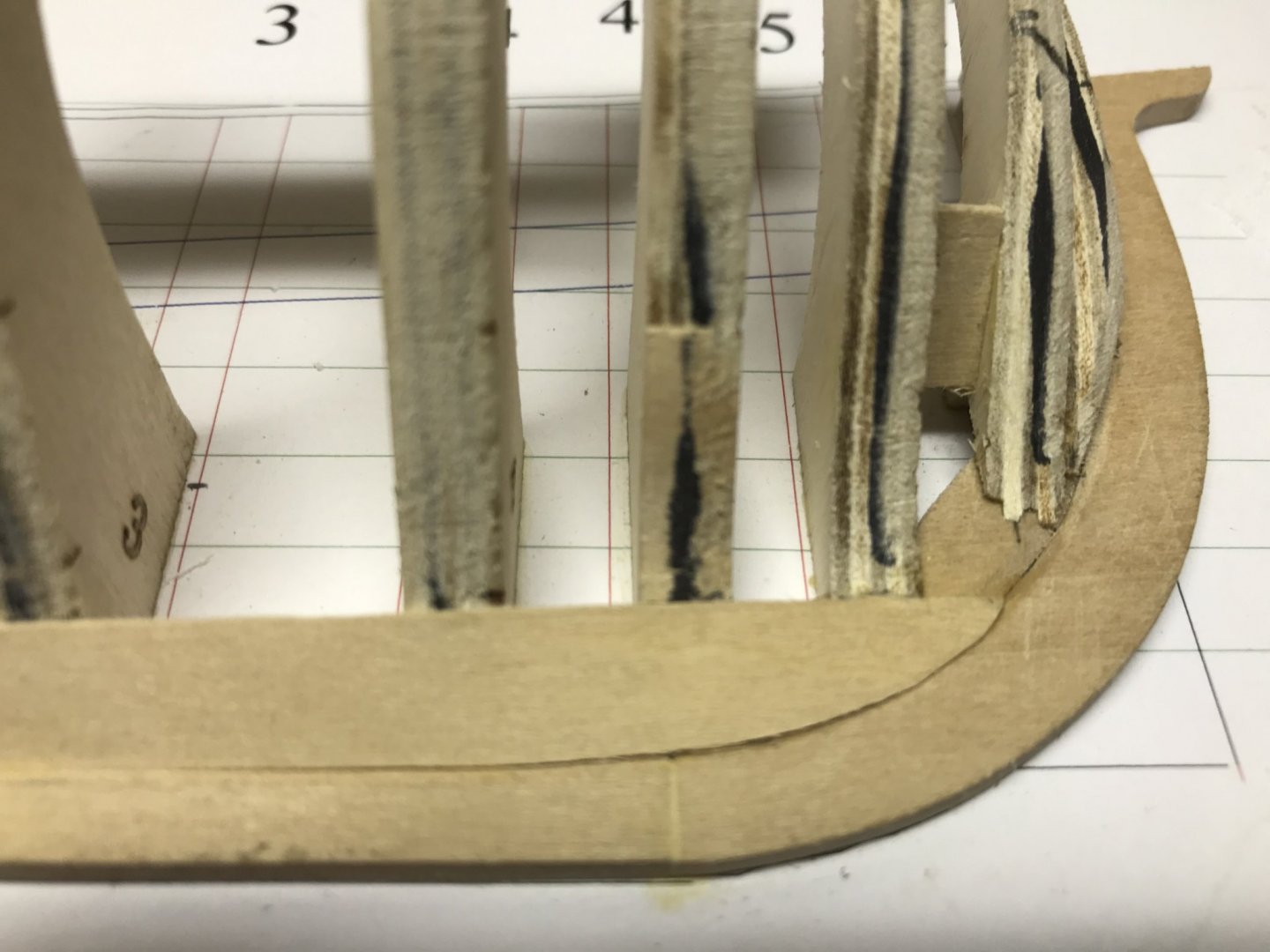
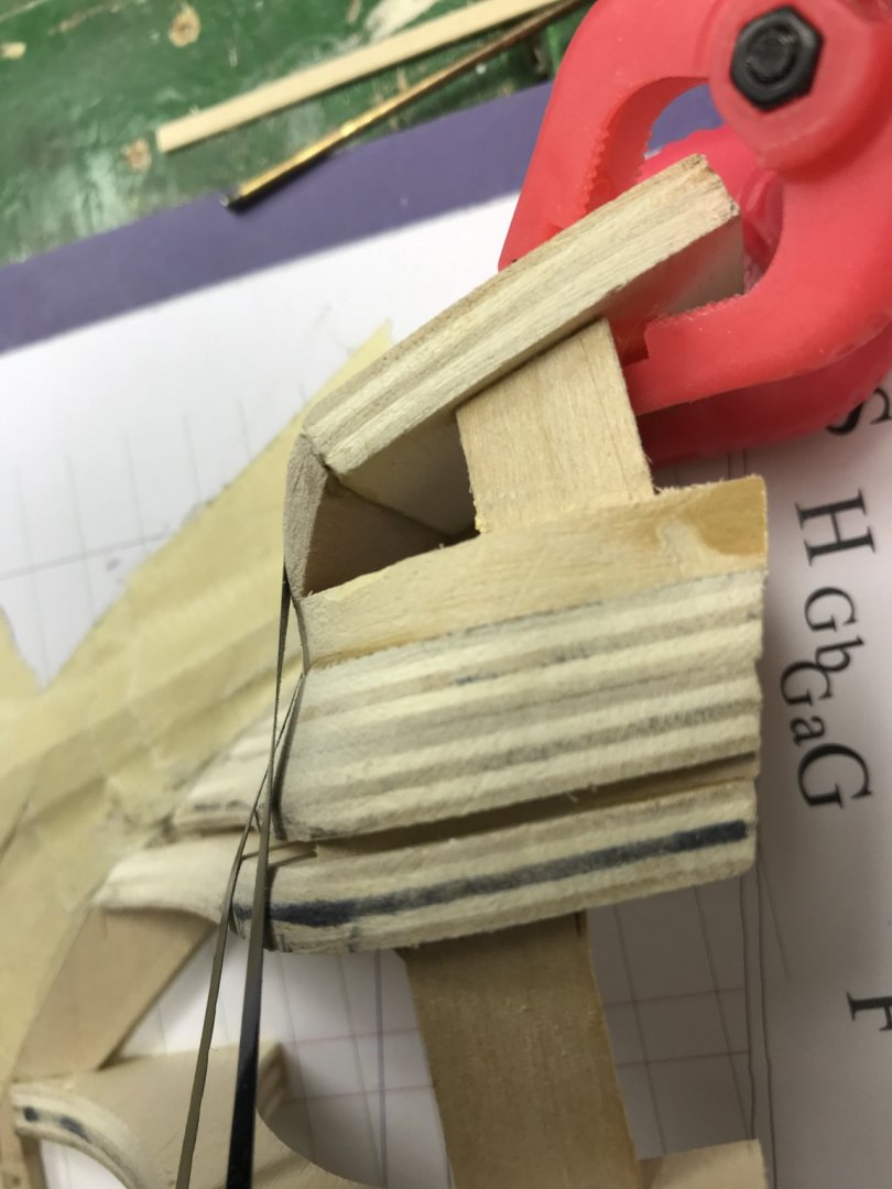
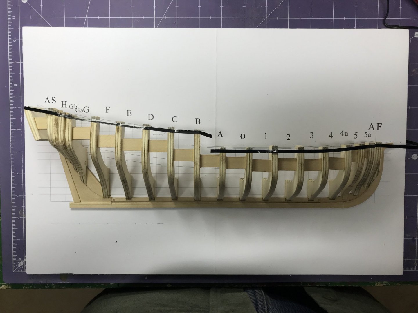
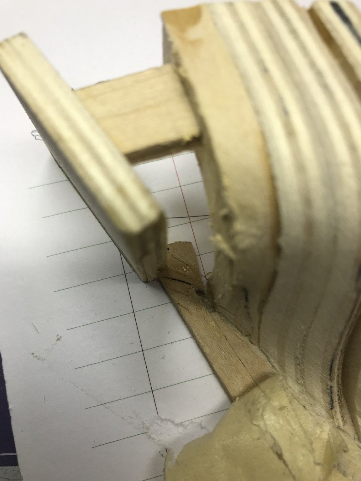
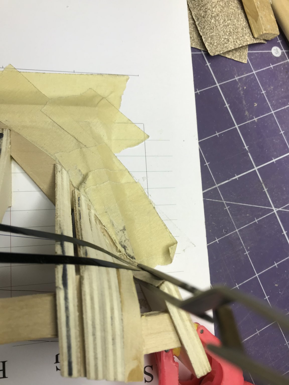
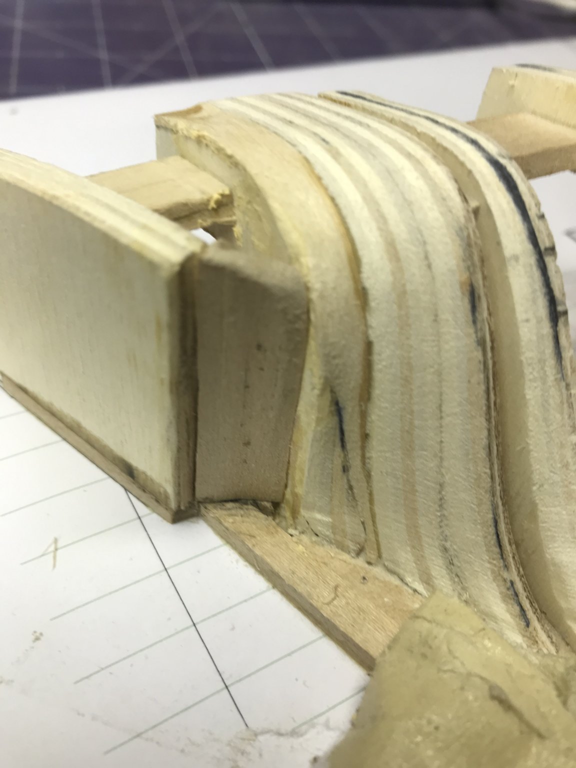
It took me a while, but I figured this thing out. As usual, it required getting the right tool for the job. I chose, in this case, bourbon. This stuff has a thousand and one uses, I swear. The fundamental problem, I figured out, was the placement of the counter. The instructions do say "it sits on the curved part of the L-shaped piece already glued to the plan." The thing I didn't understand that was that the bottom edge of it needed to conform with the bottom edge of the L-shaped piece. I had the joint between the L-shaped piece and the deadwood running down the center of the edge of the counter. That tiny difference, well, it made all the difference. I cut out the counter. You can see where the counter had been glued. So then I reinstalled it, higher by a little bit, and, of course, that changed the whole geometry of the stern. I did some cutting, shaping and carving and came up with this. This is a difficult spot to take a picture of, but I think you can see the difference between before and after. Now the pinstripe lays flat against the hull all the way around the stern. Dan


-
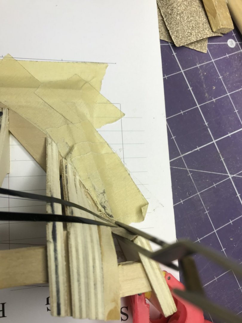
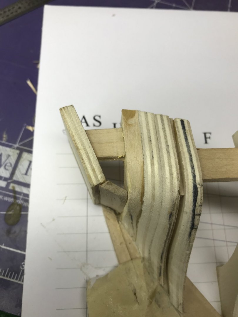
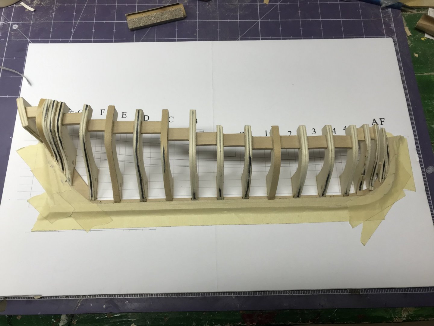
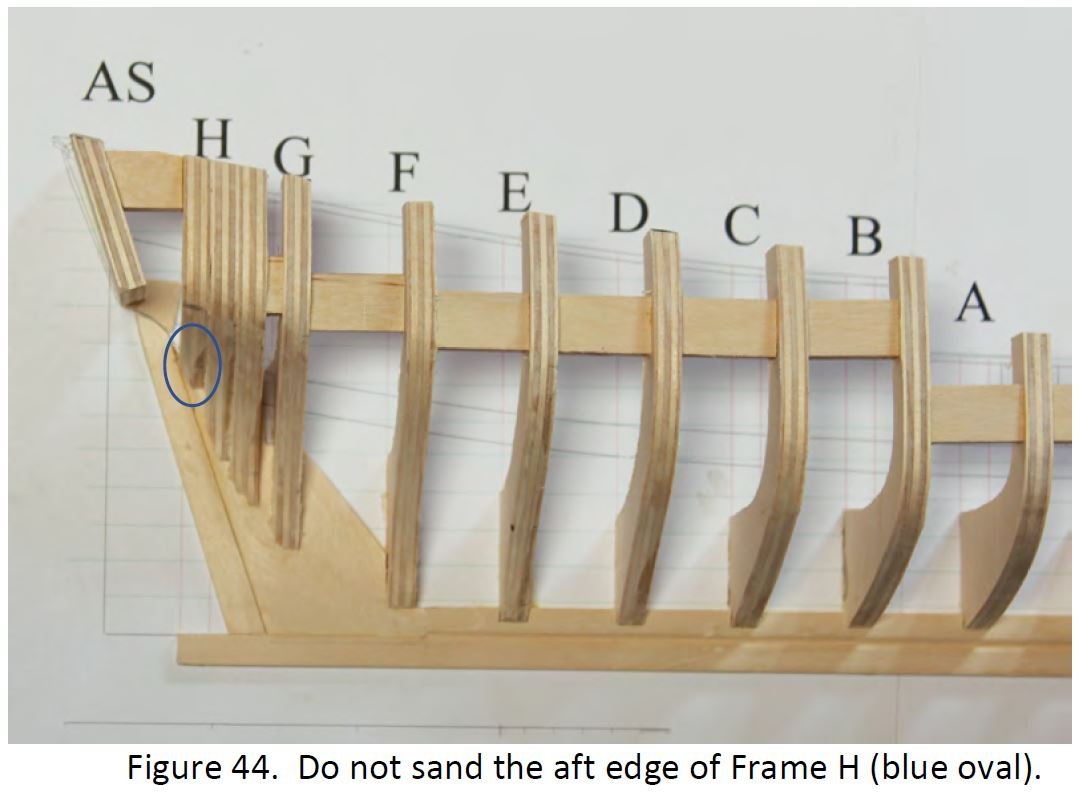
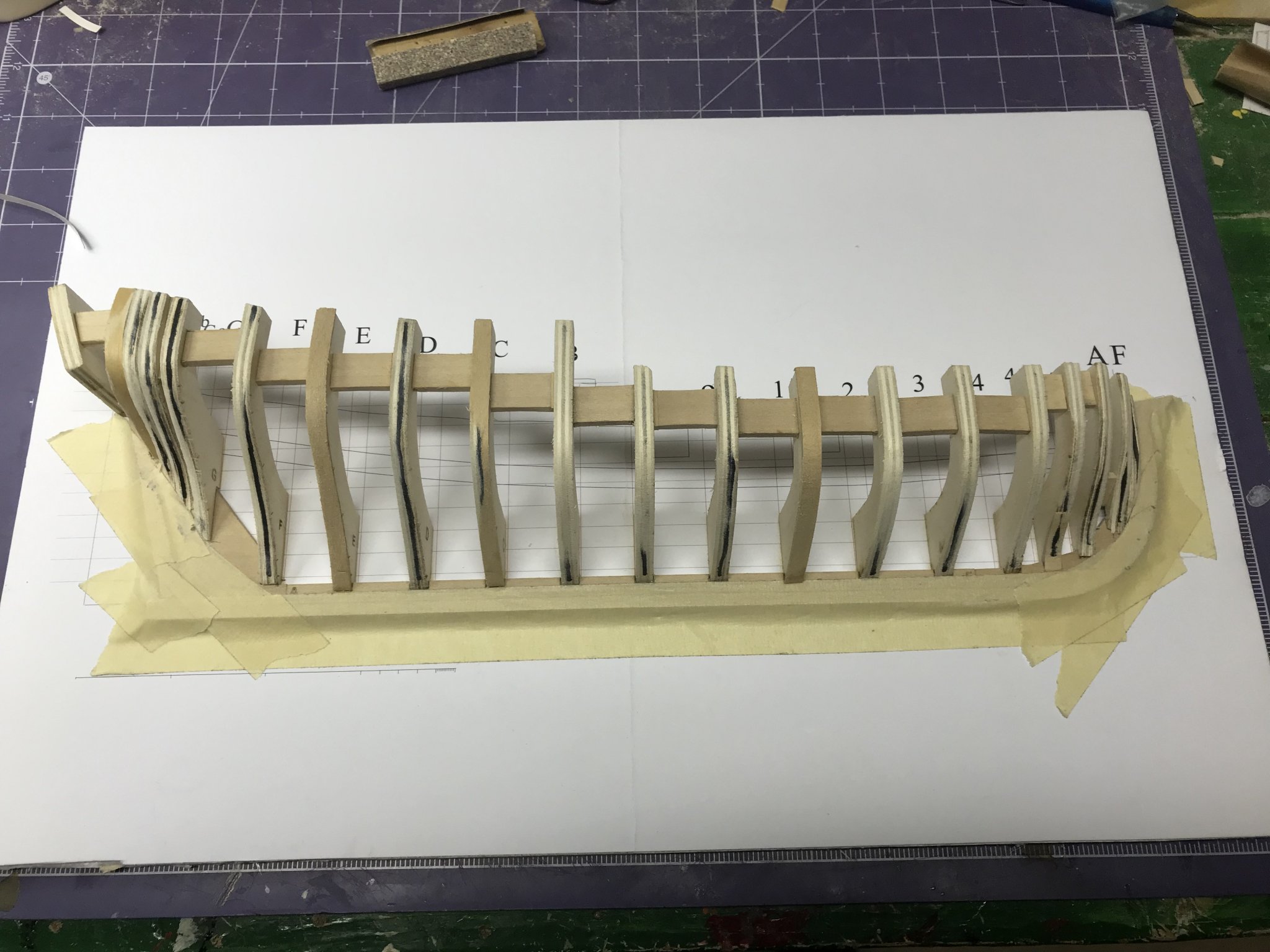
Work's been progressing on my half hull, although slowly. Toni, in her instructions says about fairing the hull, "[t]ake your time and take several breaks. It took me several hours spaced over a few days until I was happy with the hull shape." Okay. I can say it has taken me many hours over several weeks ... and I'm still not convinced I've got this right. I've built up some frames and cut down others, as can be seen here. Working around the stern confused me quite a bit. The instructions say, "Do not sand off the aft edge of Frame H, as seen in the blue oval in Figure 44. This is where the counter will be installed later." Of course, I found it difficult not to sand off some of that aft edge, but I shimmed it back to its original state, sanded more and installed the counter. I'm going to jump ahead a little because, at this point, I thought I was golden. Counter's installed; frames faired. On to the next thing: marking out the wale. The instructions say, "Using the same technique employed to mark the top of the frames (machinist's square), mark the top and/or bottom of the wale." Well, that's quite a trick because the spacers already installed obscure, in my cases, the curves on the plans showing where the wales should be. I did all kinds of contortions with my machinist square and other tools and implements to get these lines marked out. In some cases, it just wasn't possible to mark both sides of the frame or even get to some of them. When I connected the lines, it looked like I'd done so coming off a three-day bender. We discussed this at the NRMSS meeting last night and the consensus was that this step should be done before putting in those spacers. If I'd done that, this would have taken five minutes. As it was, it took quite a long time to get to something that looked reasonable. Now that I'm at this point, I have a question about how the stern is supposed to look. I know how critical this fairing operation is. I've screwed it up in the past and it's almost impossible to cover up a bad fairing job, so I know effort put in now will pay off later. I've certainly taken off, as you can see in the photo above, the aft edge of Frame H, but I think that's okay because the counter is installed. But look at this. Should that low area be there? Should I build that up? Or just leave it as it is? Any guidance on this would be appreciated. Certainly I'm going to noodle on it some more ... because that's what I do. Dan
.thumb.JPG.df357de776b2dc5dbe5d4e7102e24d21.JPG)

-
Thanks! You're right. I'll go back and fix that... And thanks for the compliment. I've been stuck on another project because I didn't know how to properly plank the hull. This project will teach me the skills I need to work on the other project! Dan
-
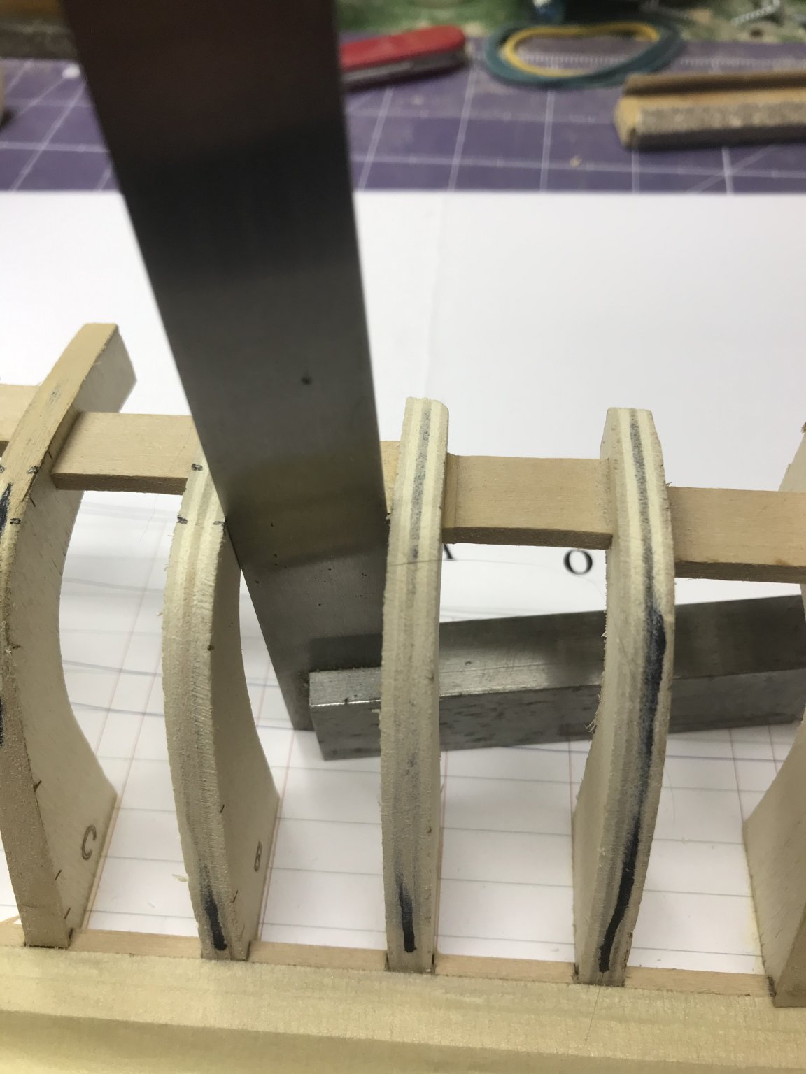
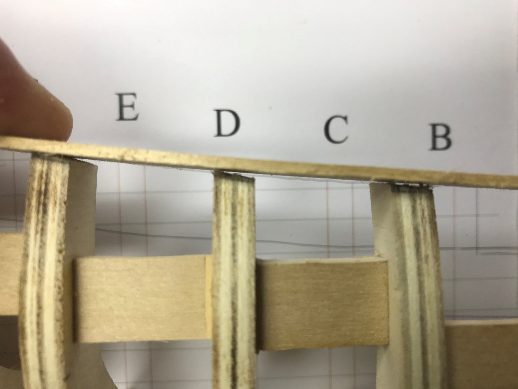
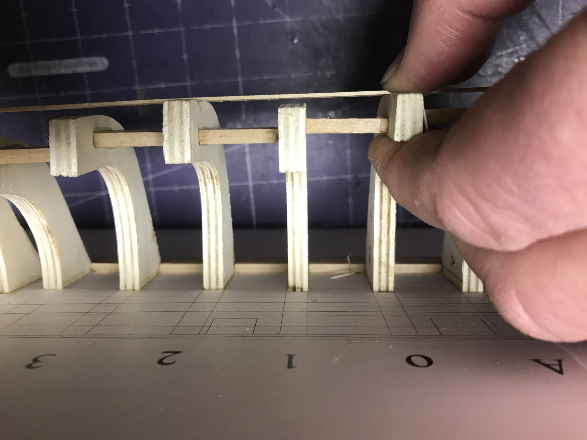
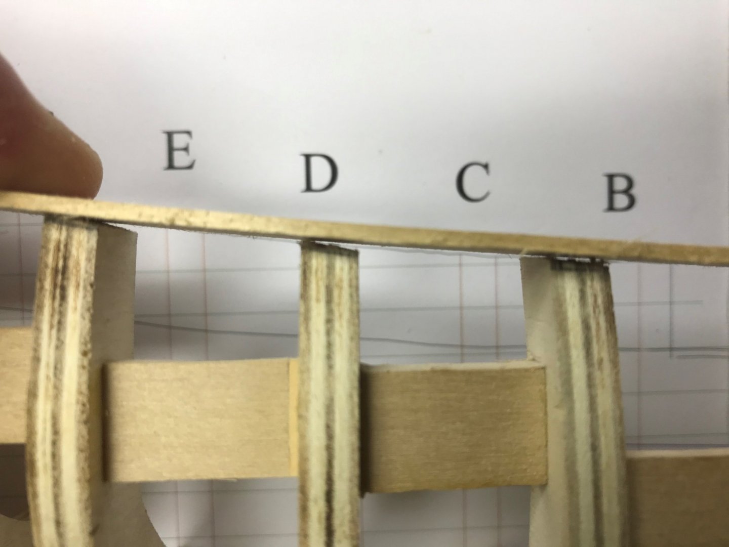
I got a little more time over the weekend to make some progress on the planking project. I sawed off the excess at the tops of the frames. I'm not completely happy with the results I achieved. When I lay a batten on the tops of the frames, there are gaps. I think I'm going to correct these before I move along too far. I started fairing the hull. I added some black lines to the centers of the frames, as Toni has suggested here on MSW. I can see this is going to take a while to get right and I think I'm going to add some wood to at least some of the frames. As you can see below, either Frame 2 is too proud or Frame 1 needs to be built up. Looking at it, I think Frame 1 needs to be built up. I can't explain why it turned out this way. The bottom of the frame sits just as it should against the building board. The notch in the keel is the correct depth. It's just a mystery to me. I started fairing, but was taking off more wood than I thought I should. Like Toni says in the instructions, this step takes a while and requires some care and frequent checking, so I'm prepared to put in some effort on this. Dan


-
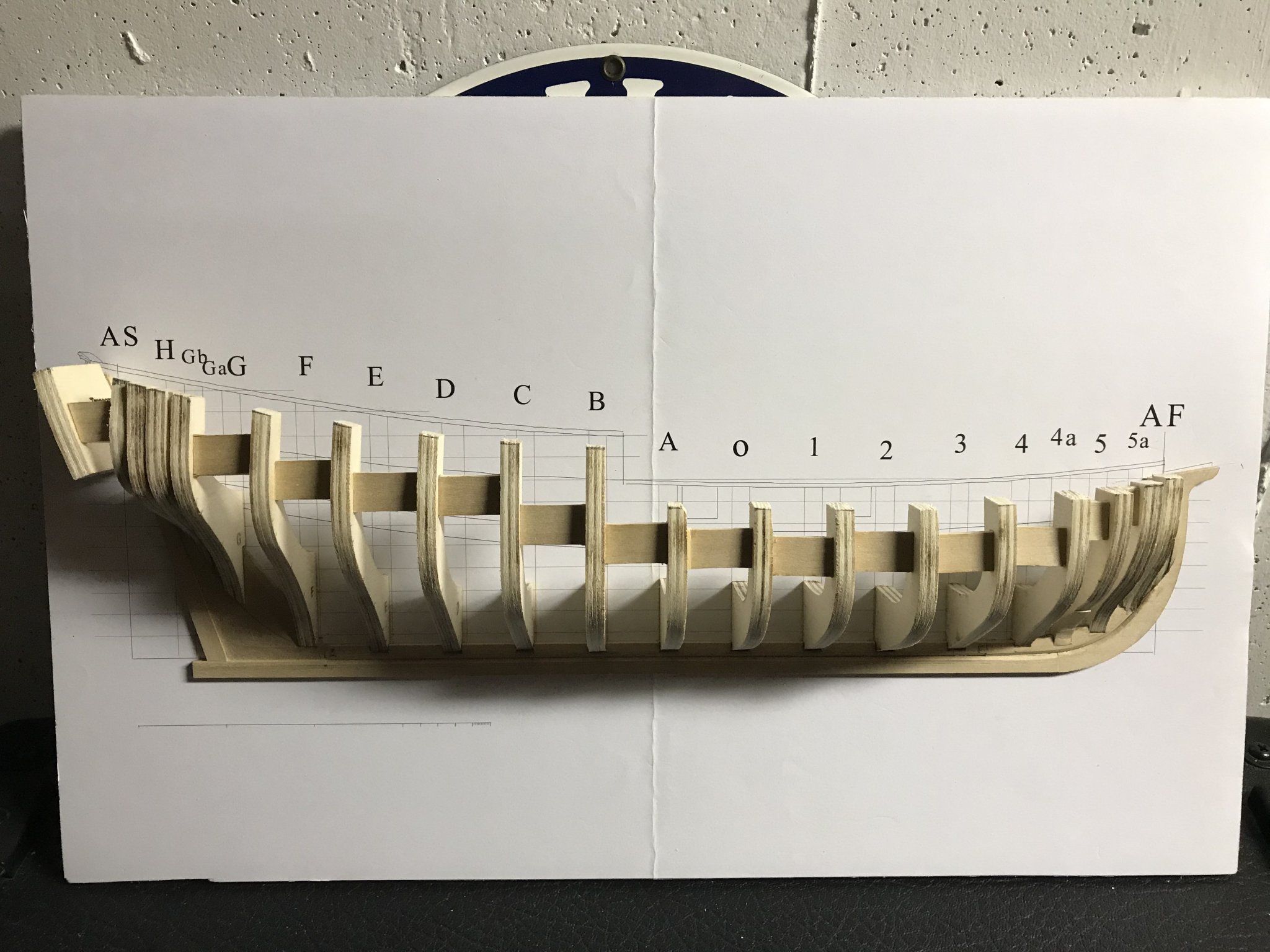
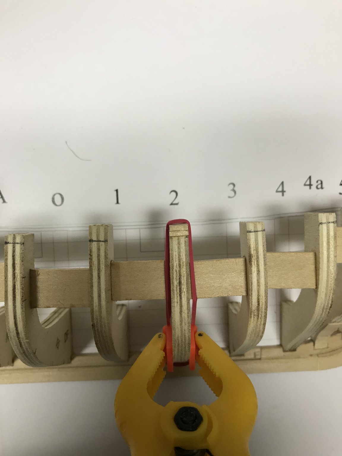
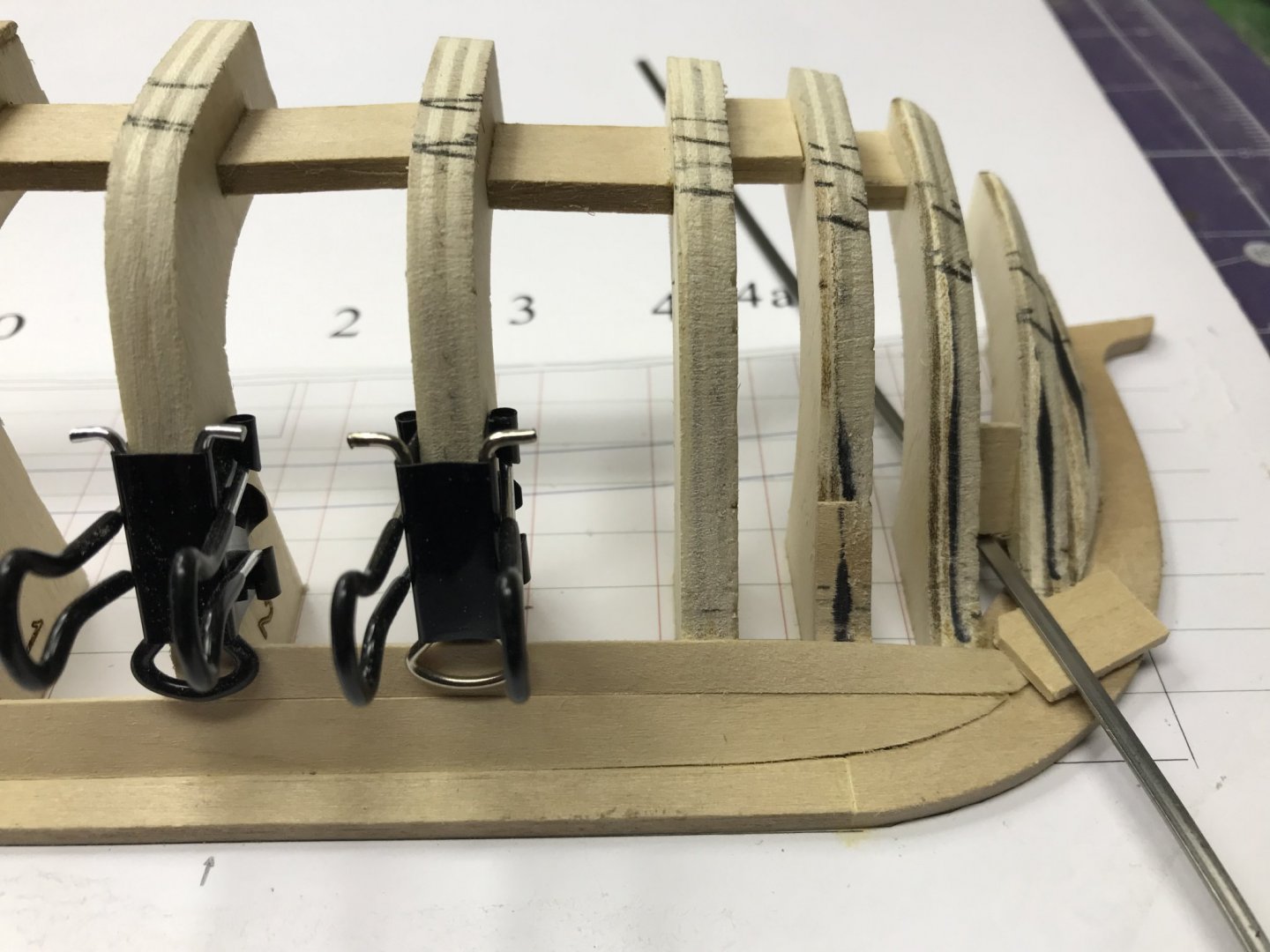
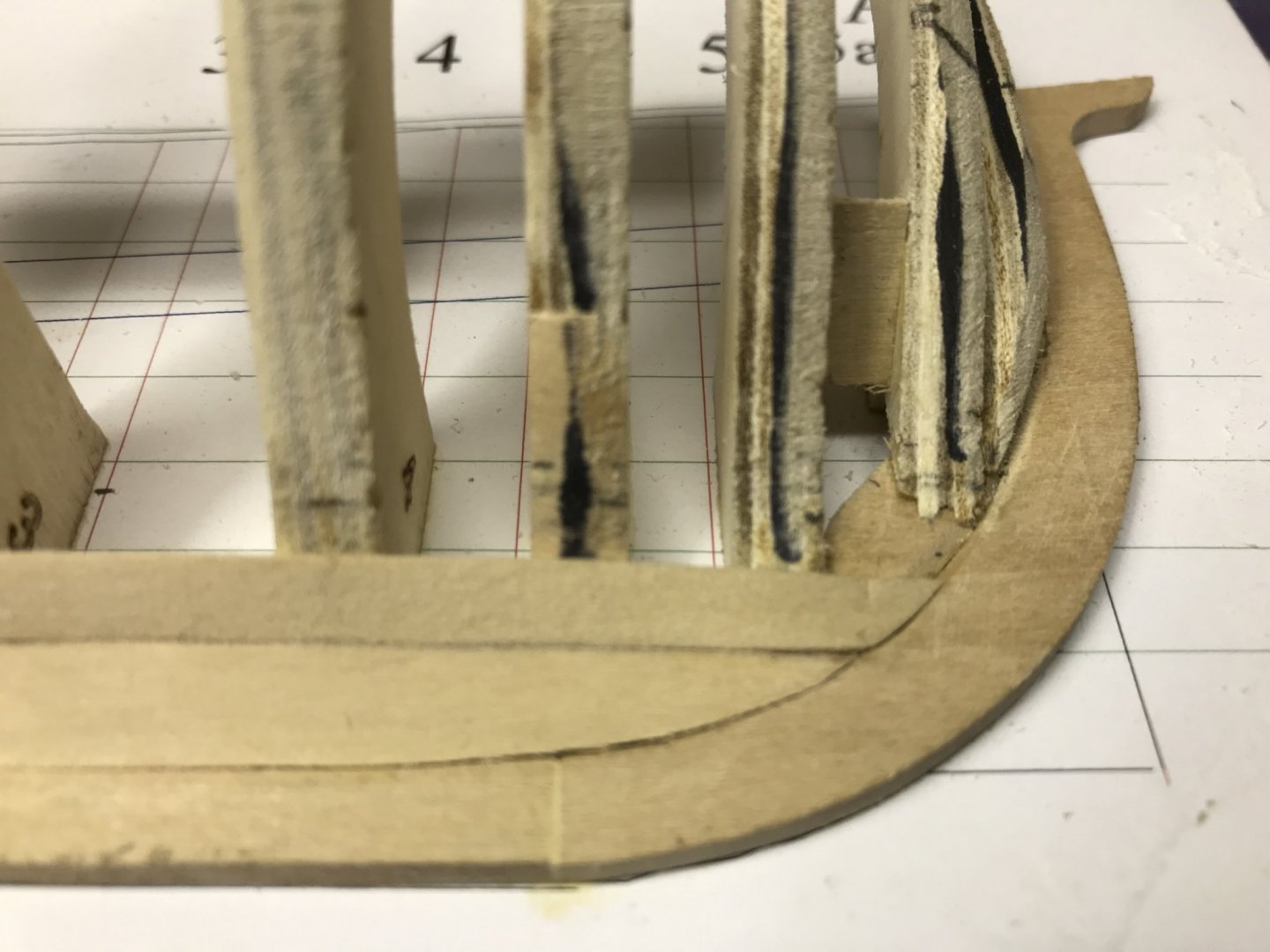
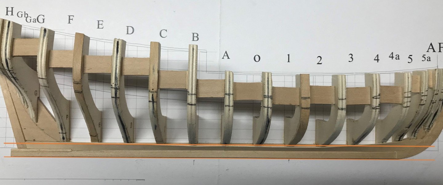
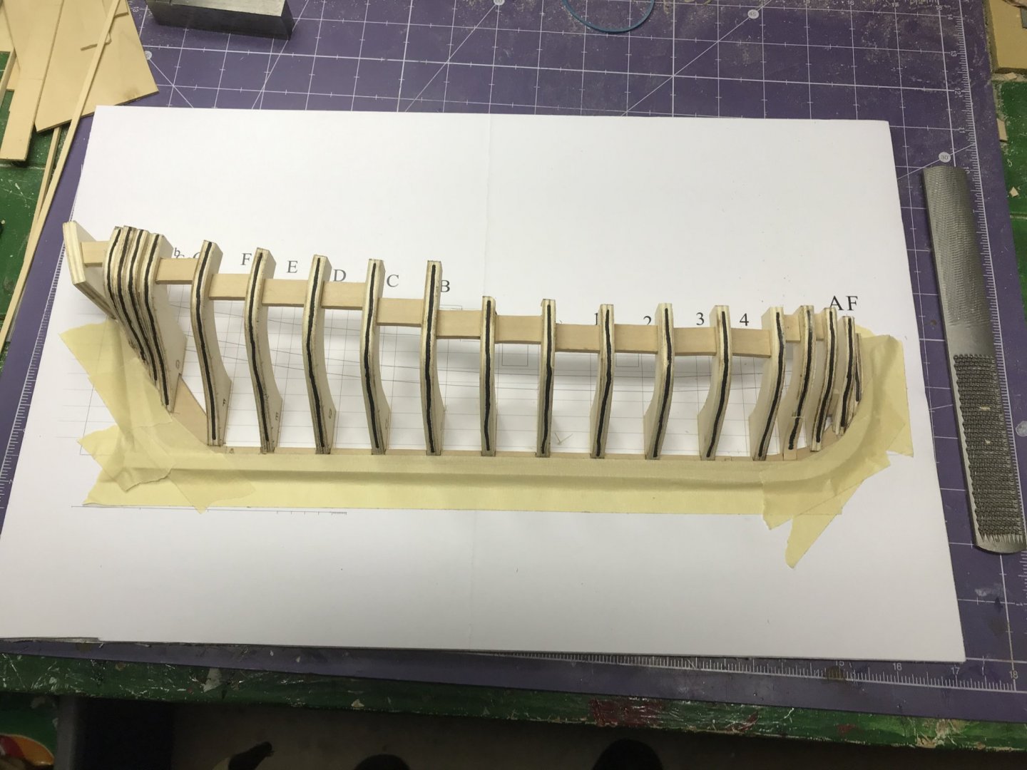
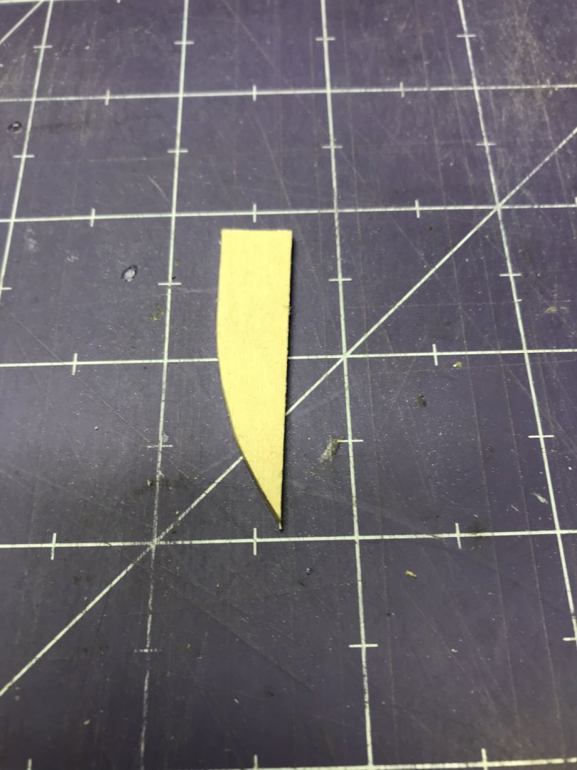
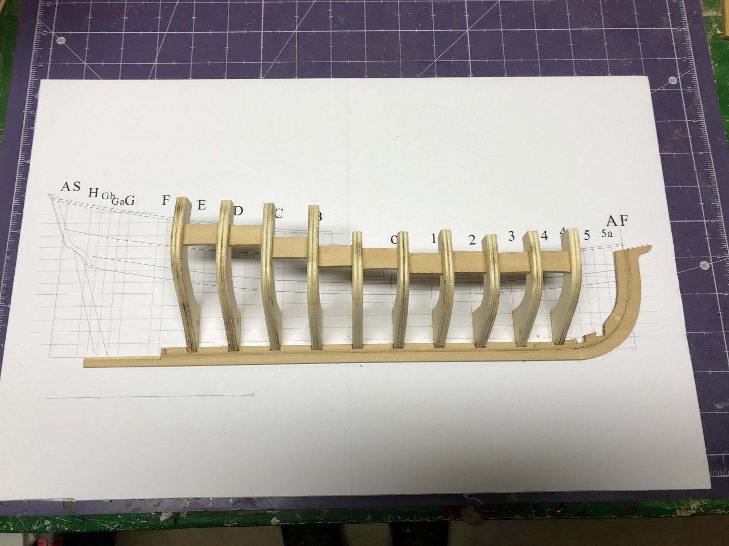
One last little detail had to be taken care of on the bow: addition of a shim that closes the gap between Frame 5A and the rabbet. I cut a shim from a piece of basswood. And installed it. Then on to the stern, I installed the transom. And that completes all the frames. I noticed when I tried to draw in the topline, that Frame 2 was just barely tall enough. I added a little shim to that. Most of it will be removed when the frames are cut down, but I wanted to be able to cut down to something, not just leave it as it was. I went over to Michael's -- a local craft store -- to get some chart tape. The clerk gave me the RCA Victor dog look. Seems you have to go to a "real art store" for that kind of thing. The nearest one is quite a drive, so I decided to go to the auto parts store and see what they had. Sure enough: pinstriping tape. Got a roll of this for about $4.00. Then I marked the topline on the model and blackened the area that needs to be removed. There is going to be a lot of fairing to be done on this hull. Some of the frames are too far inboard and the curve of the hull... Well, it was hard getting that chart tape on because the differences between the frames was very great. Time for a lot of cutting and chopping now. Dan


-
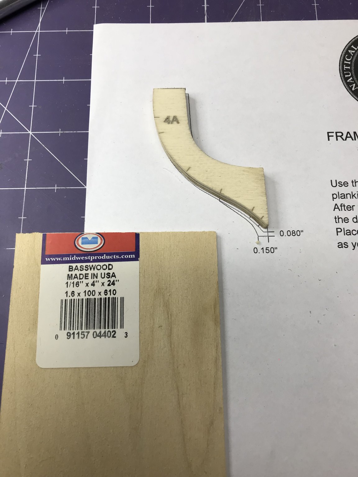
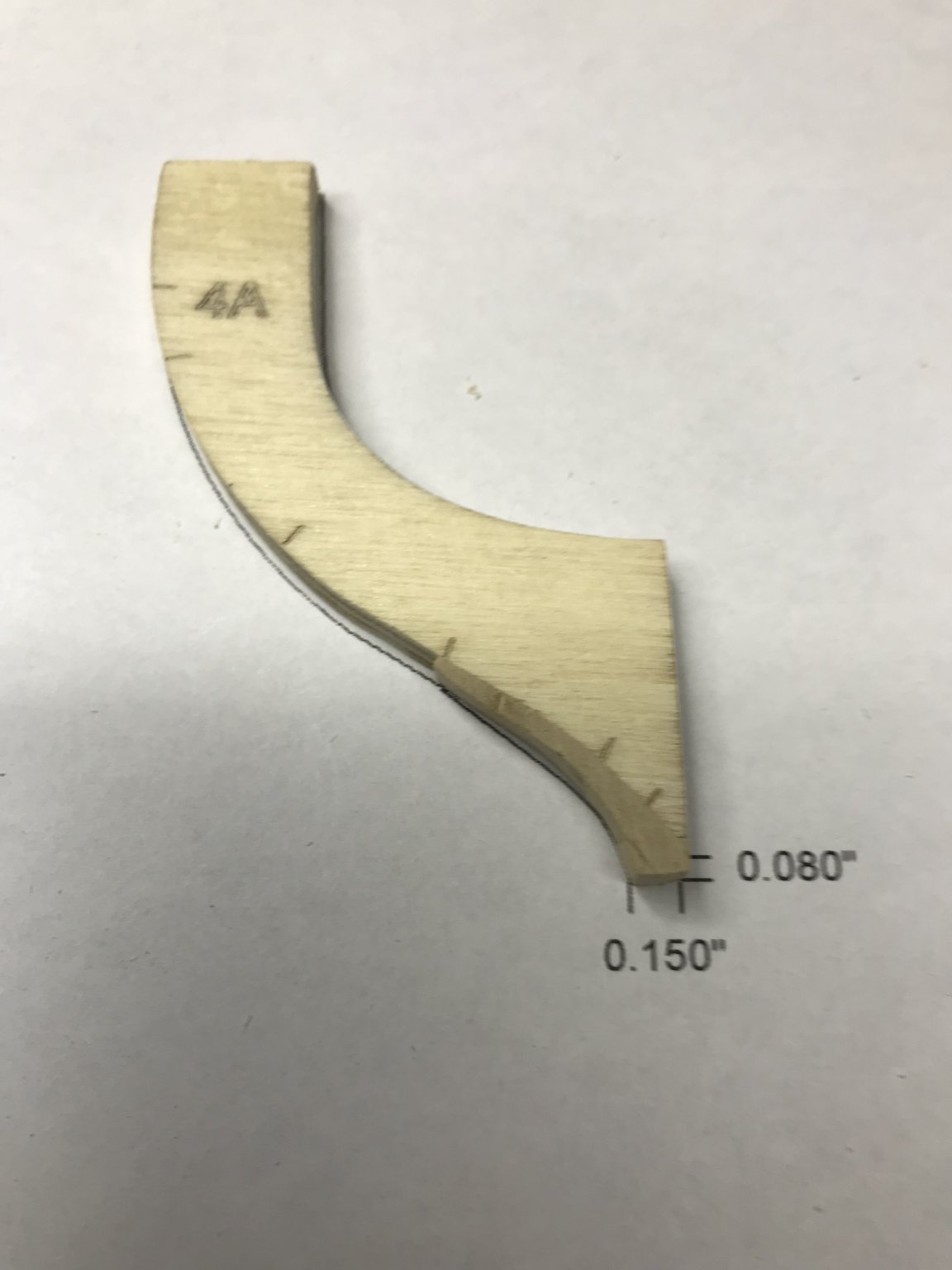
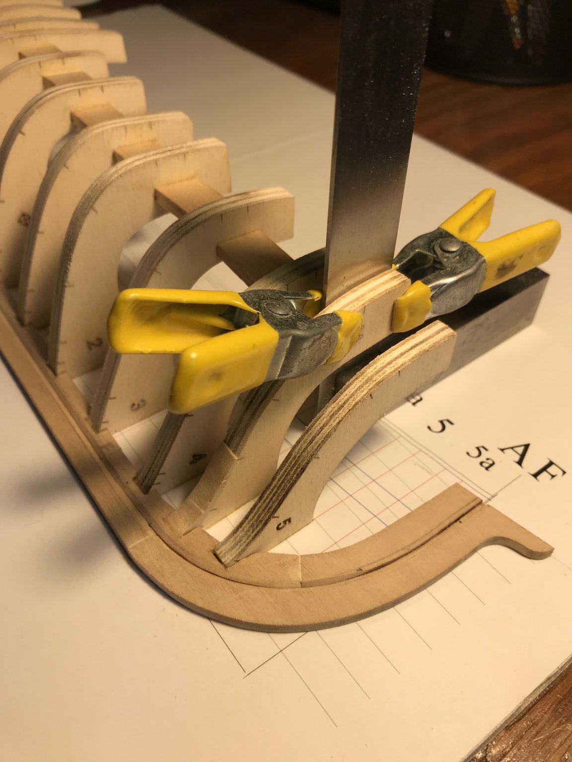
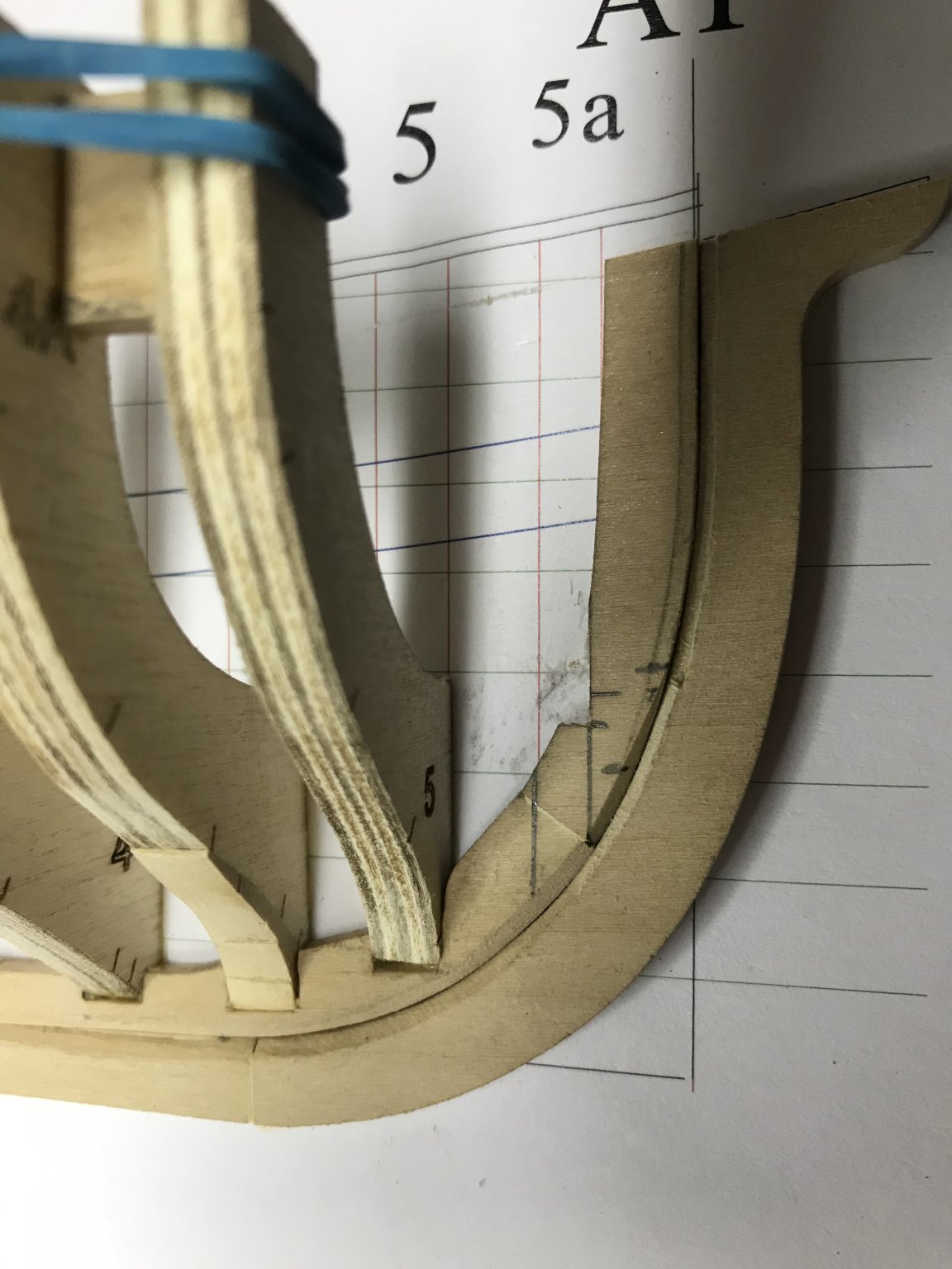
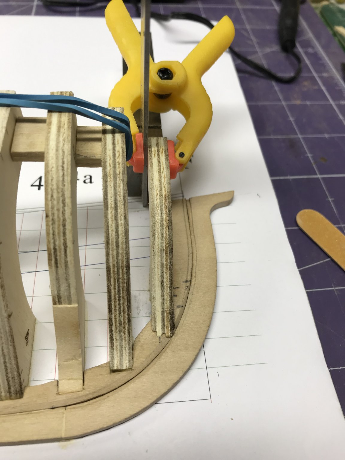
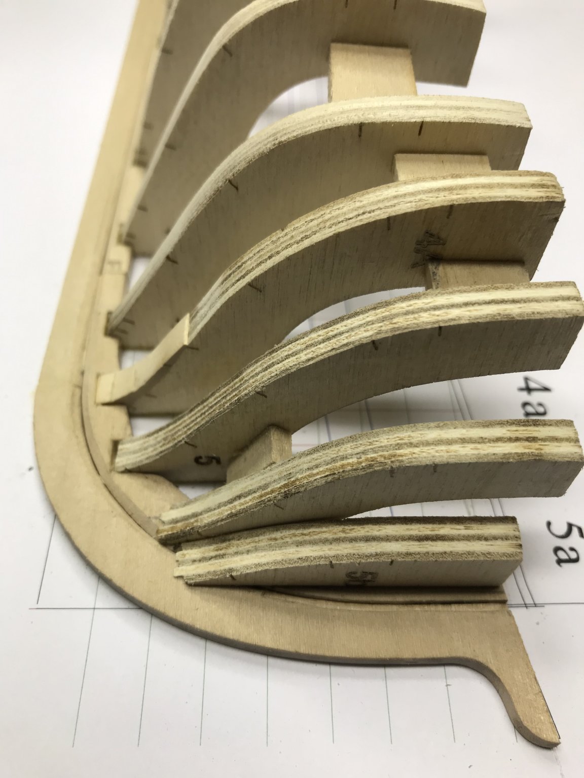
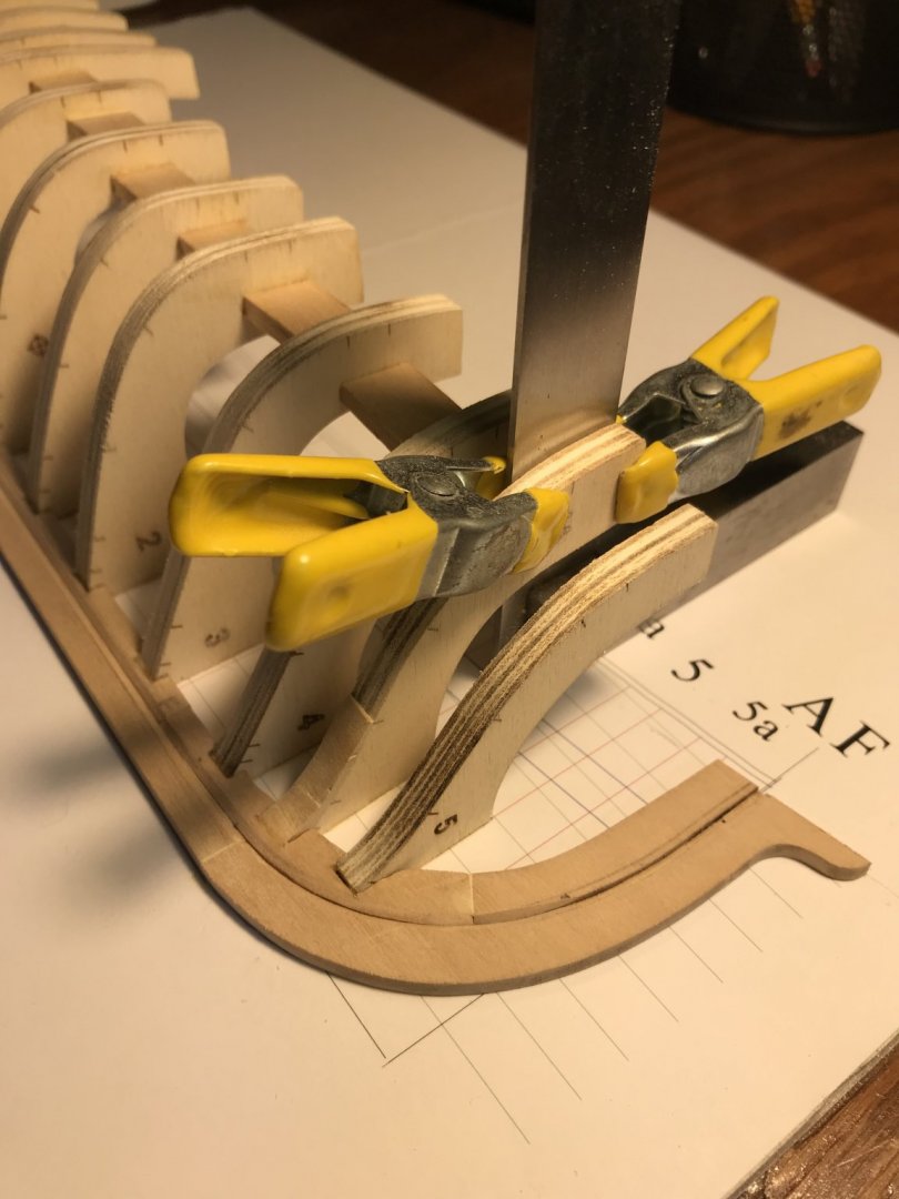
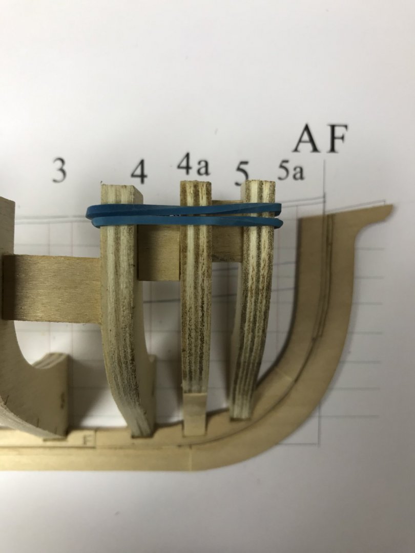
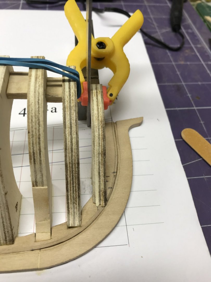
The next step required some surgery to Frame 4A. As you can see on the errata sheet included with the kit, Frame 4A needs a little wood added to it to bring it to the right shape. I had some 1/16" basswood in my wood pile which I used to make these modifications. I needed three layers to get it right. Here's the finished product. And here it is installed. A little trickier to get the clamps in there. Then I installed the spacers. The next frame (5A) is a little tricky to install. There is no notch in the keelson for this frame because cutting one would have made the keelson too thin. I followed Toni's directions on this, extending the lines for Frame 5a onto the keelson and then figuring out where the notch has to be to get the forward corner of the frame almost to the keel rabbet. You can see where I cut the keelson away and cut the notch. In the end, a little of the bottom of the frame chipped off. I needed to sand it a little to get the back of the frame to contact the building board. Rather than shim it up, I decided to cut it down... I hope that was a good call. Finally, I installed Frame 5a, the final forward frame. (Enough alliteration for you?) Dan


-
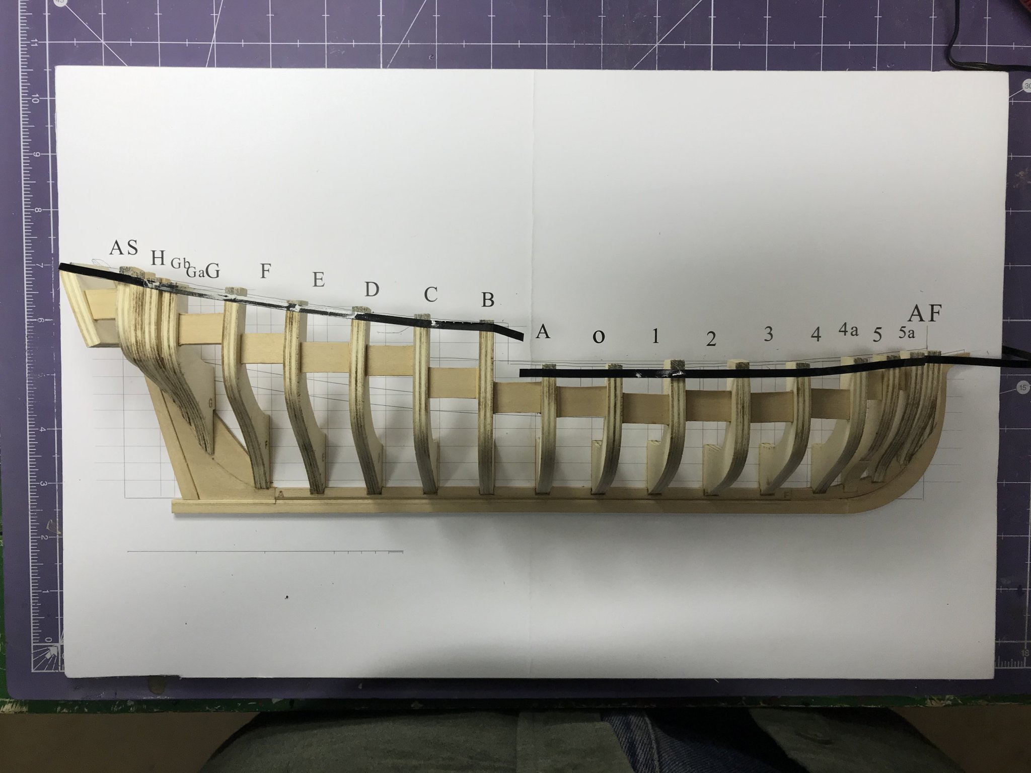
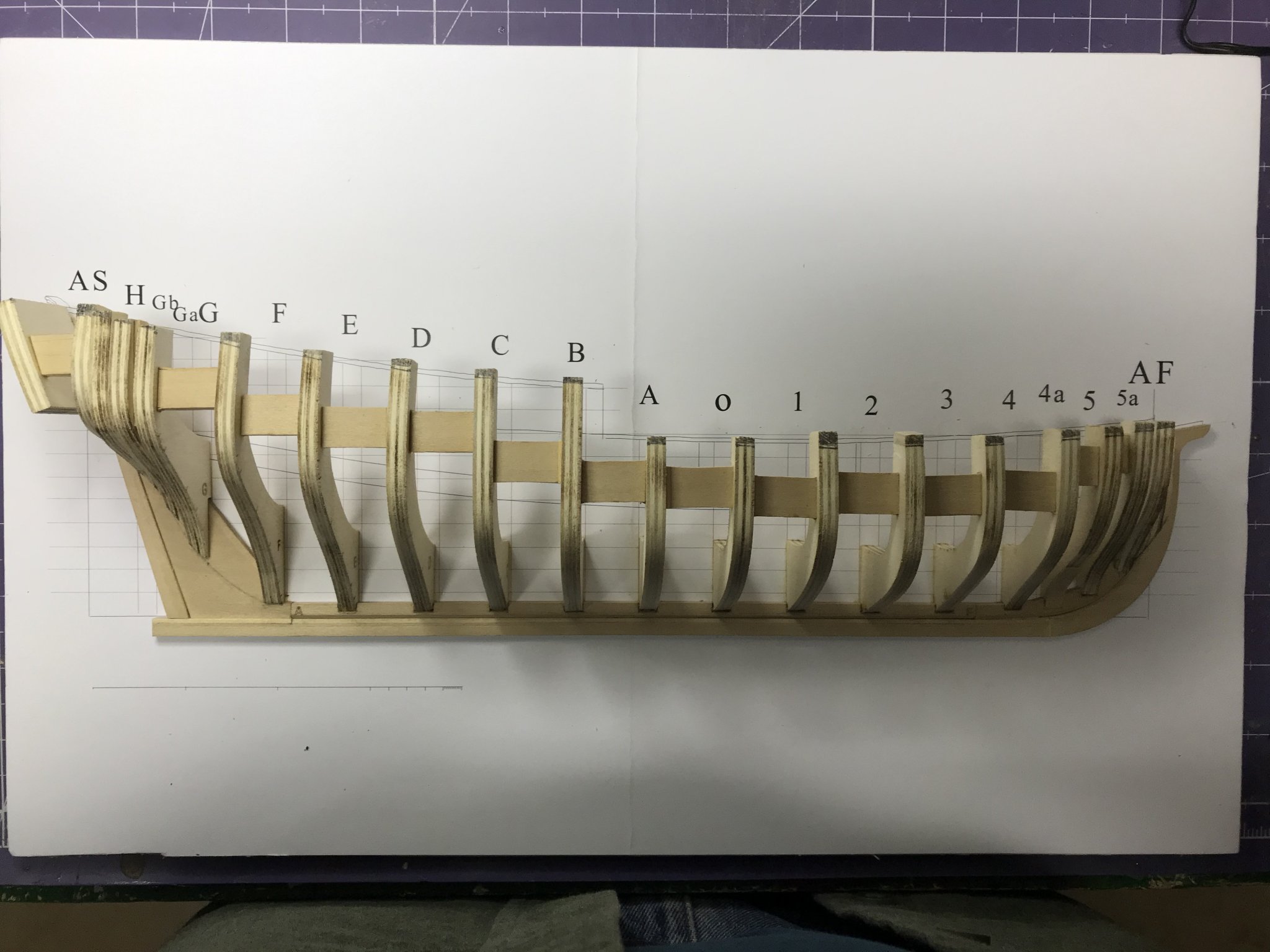
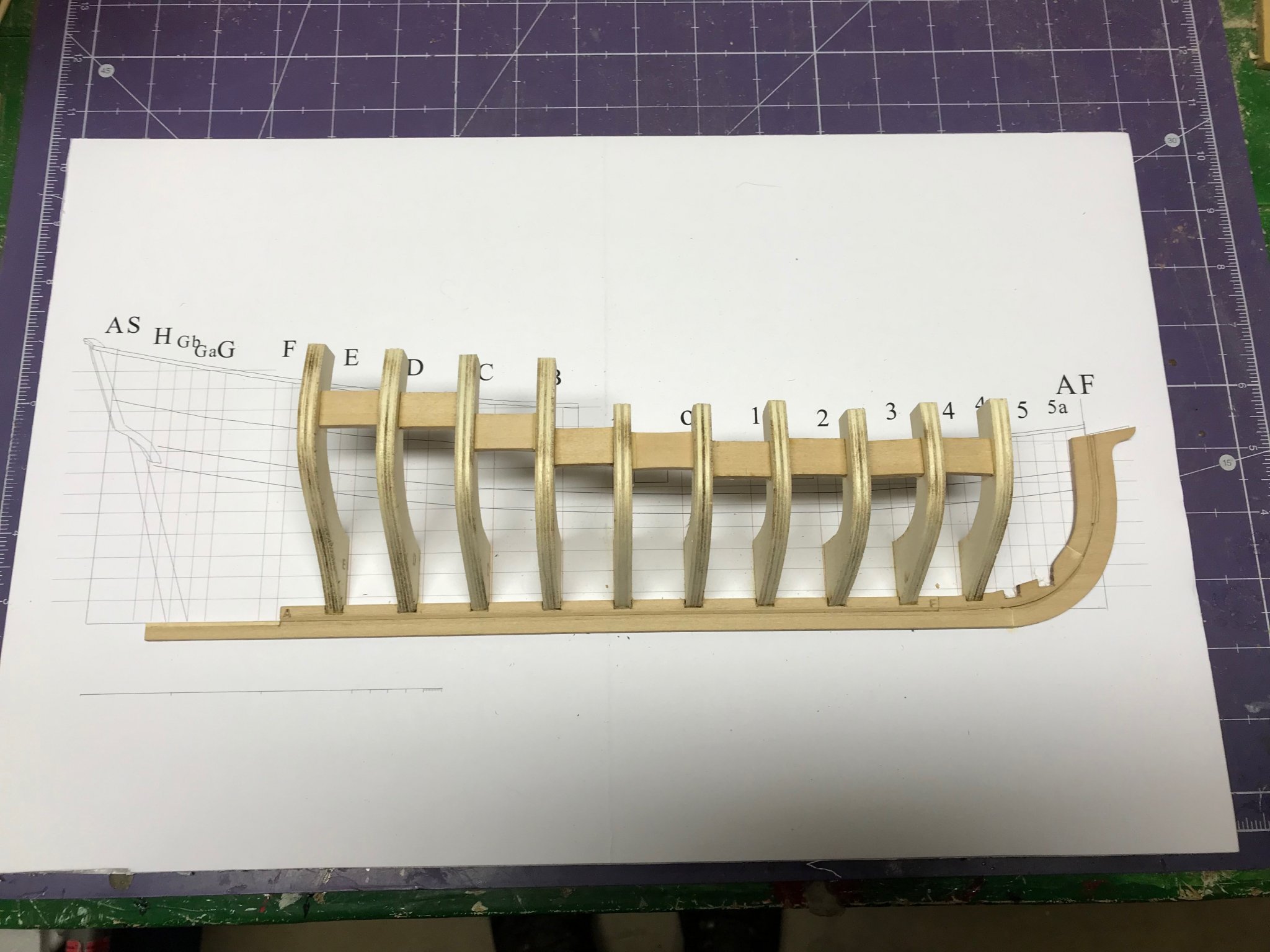
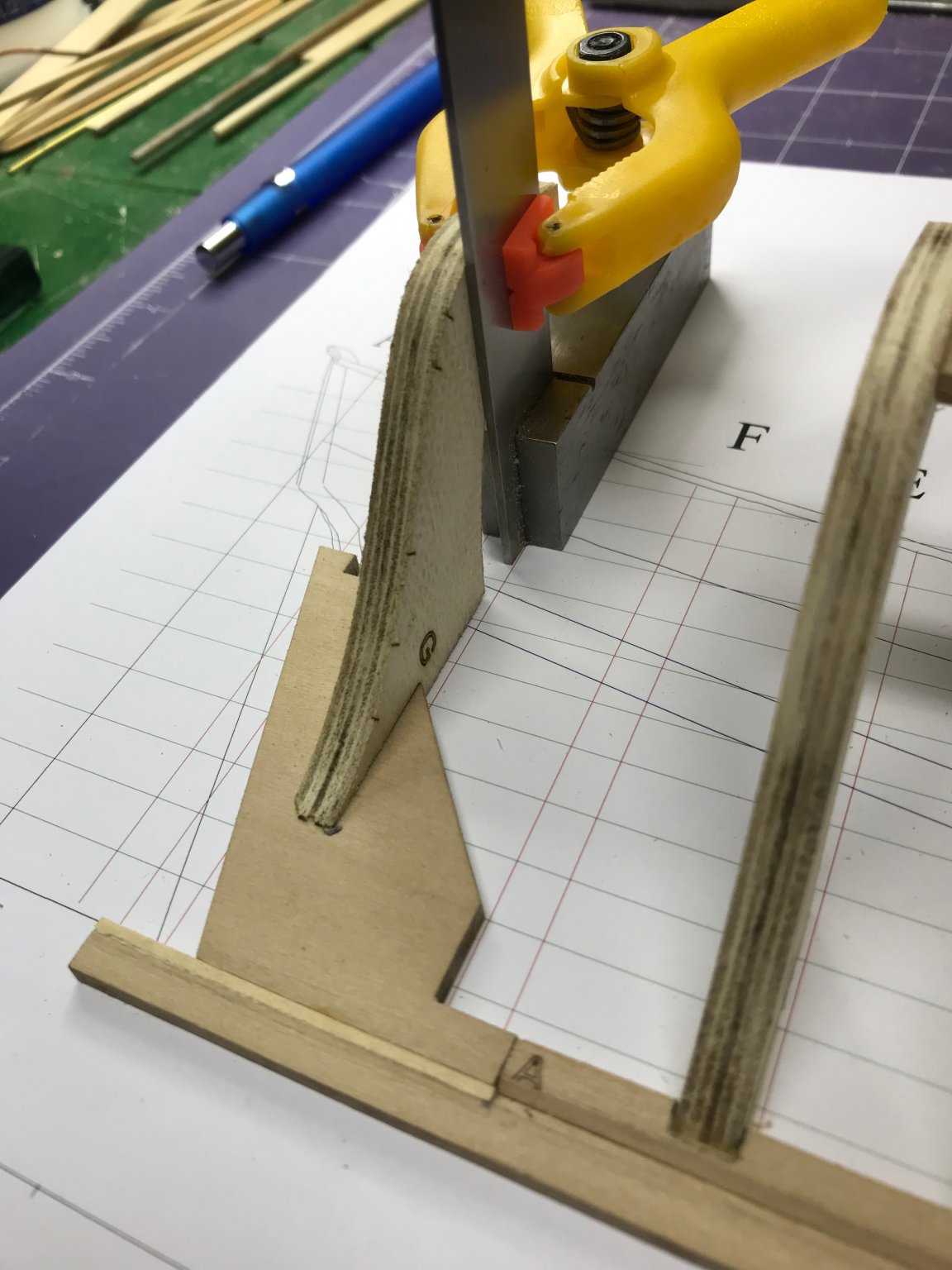
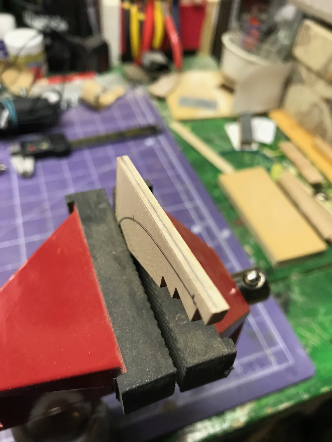
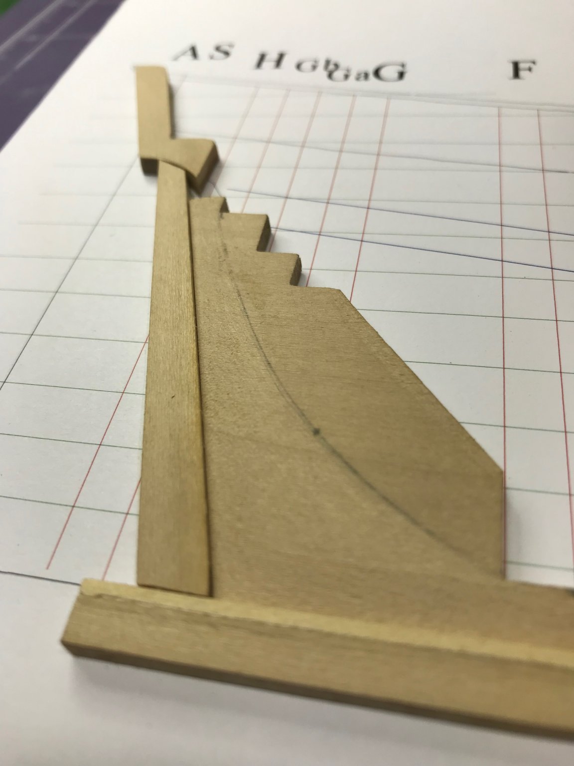
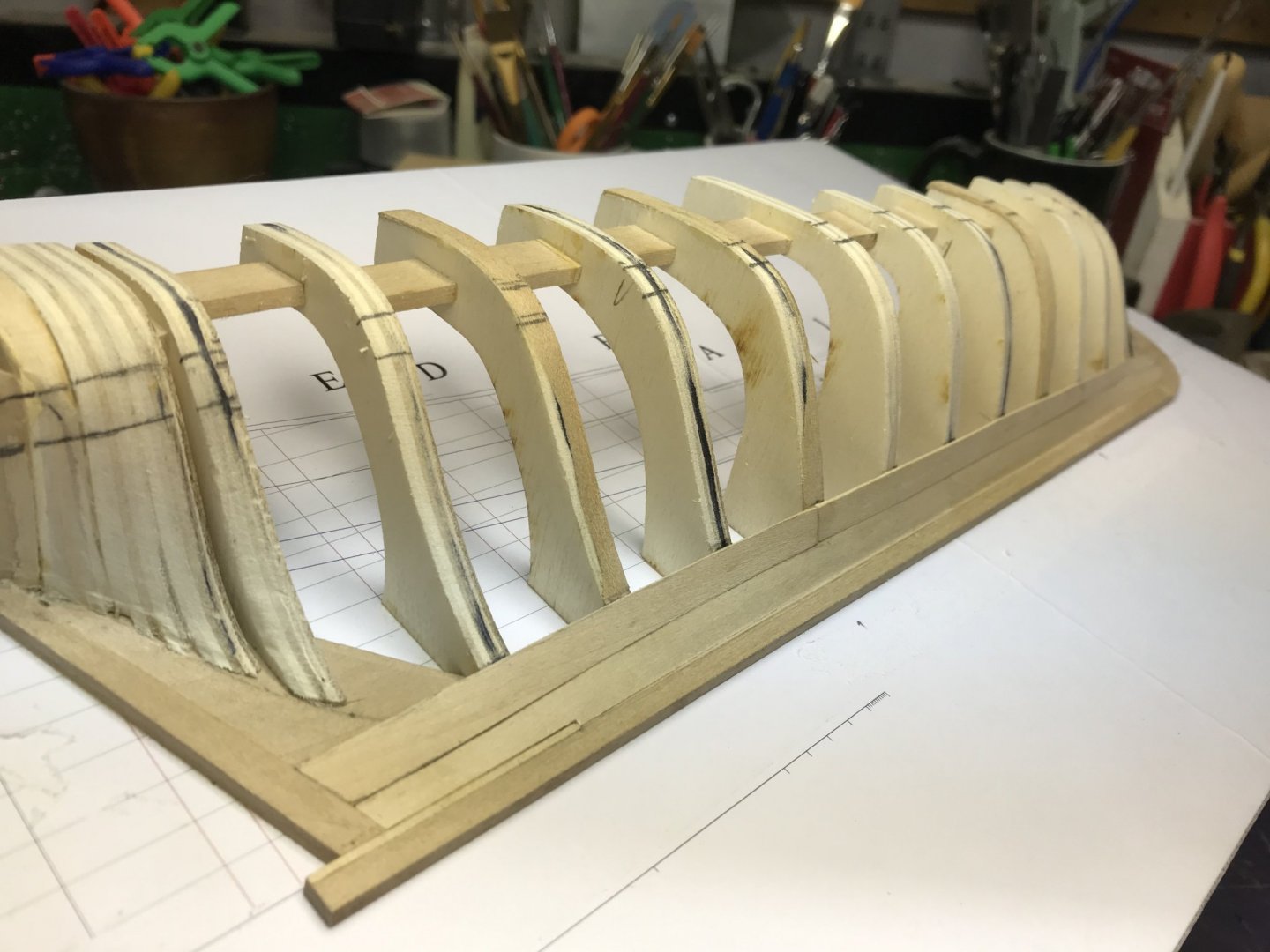
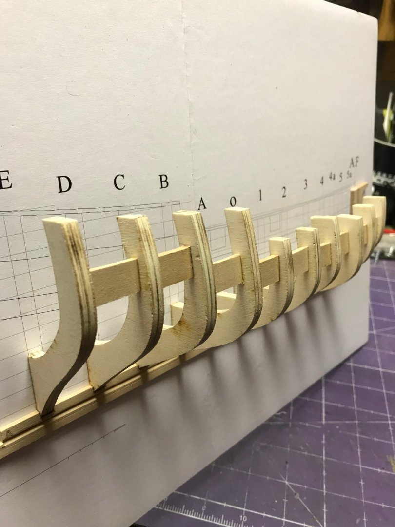
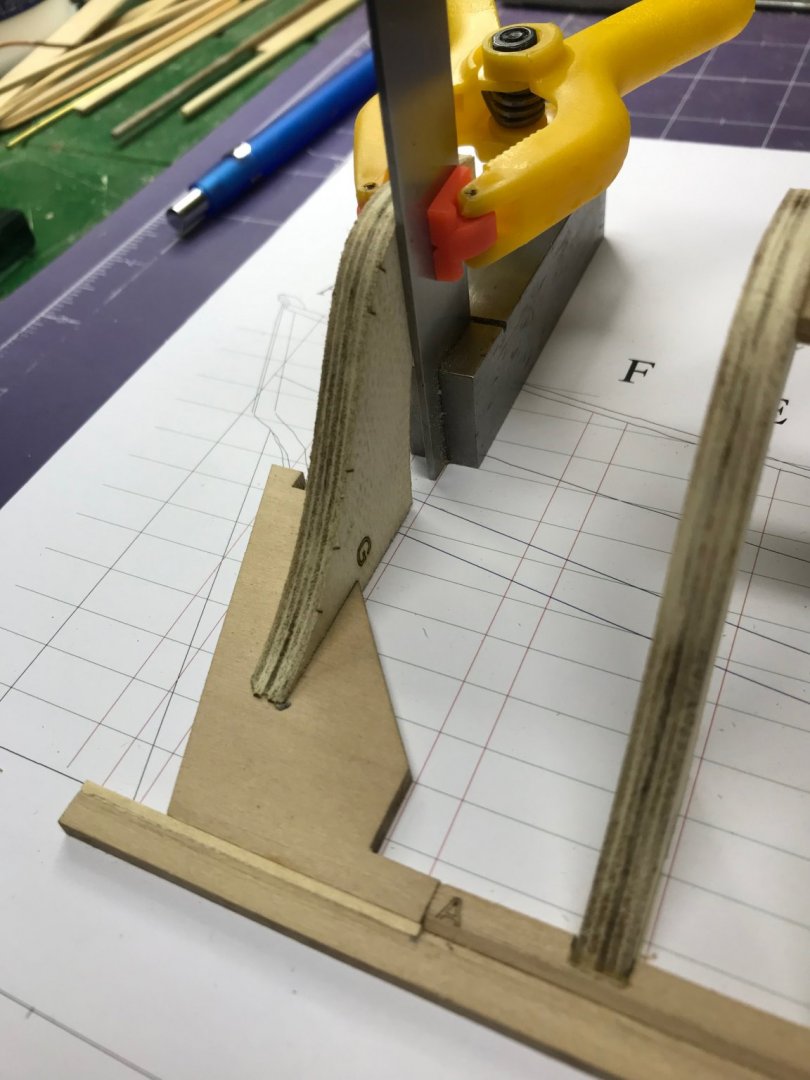
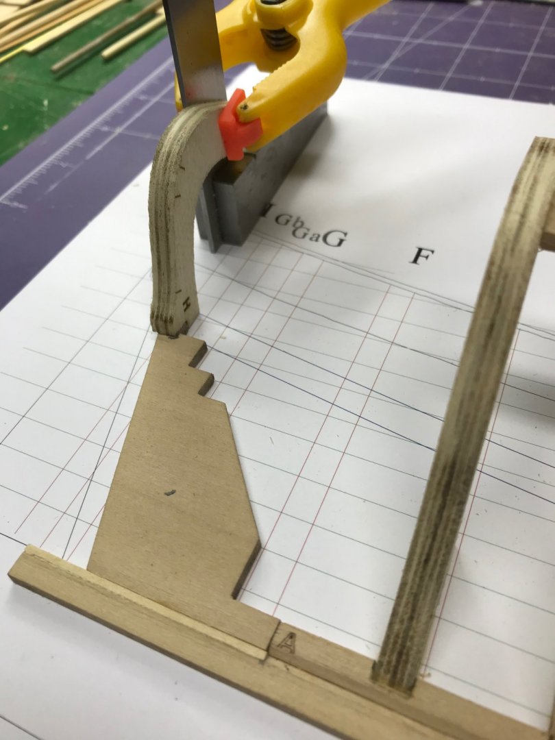
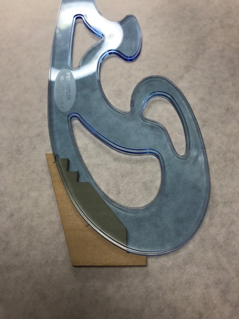
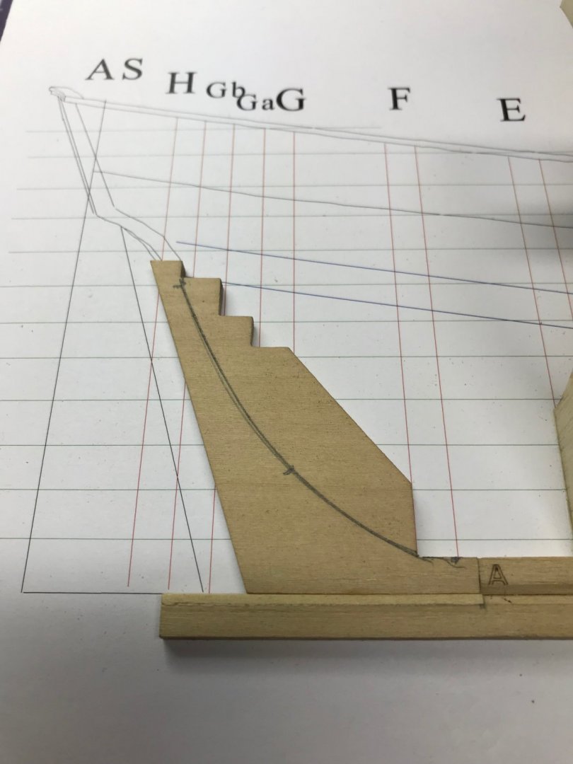
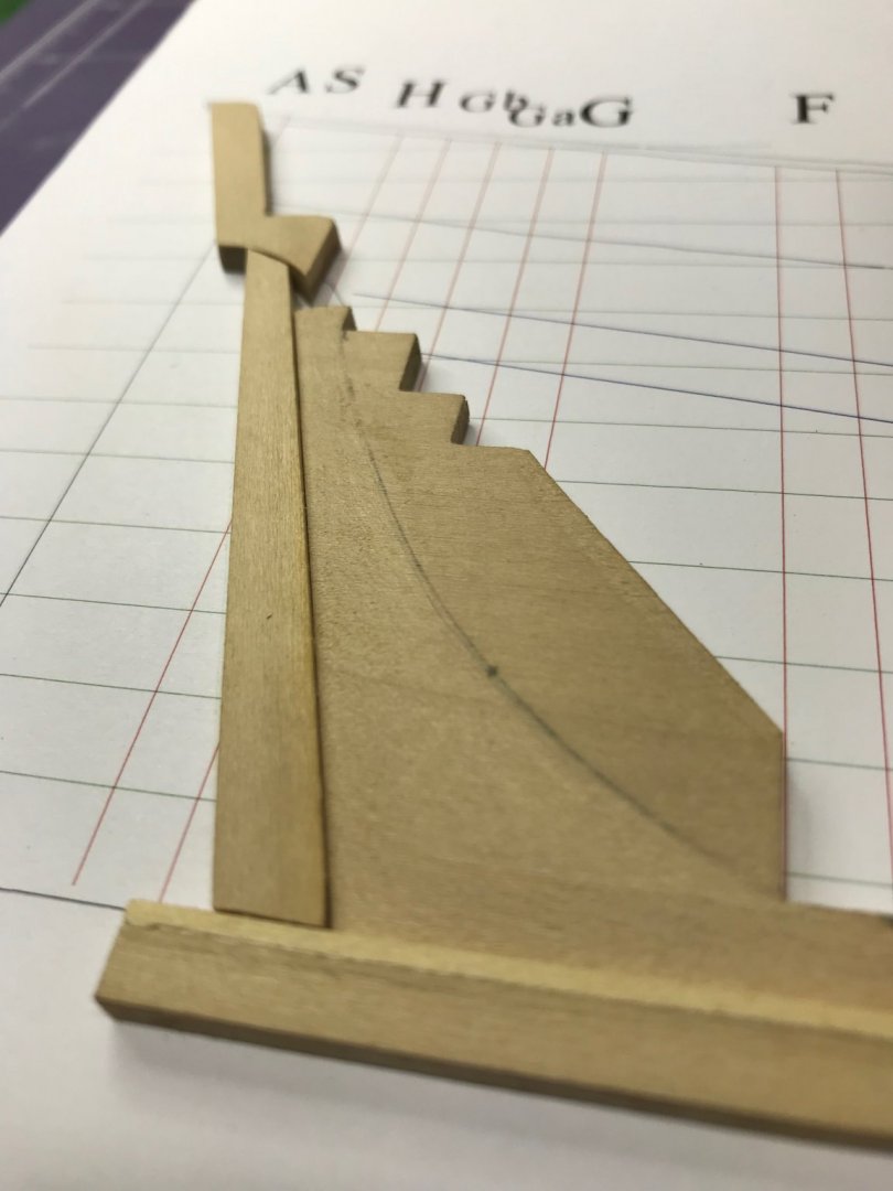
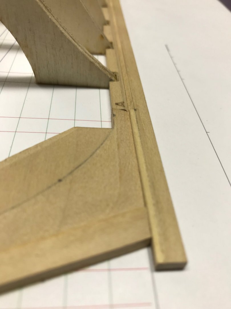
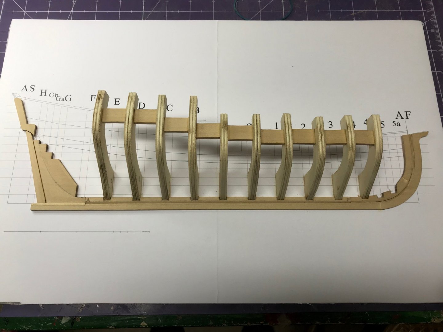
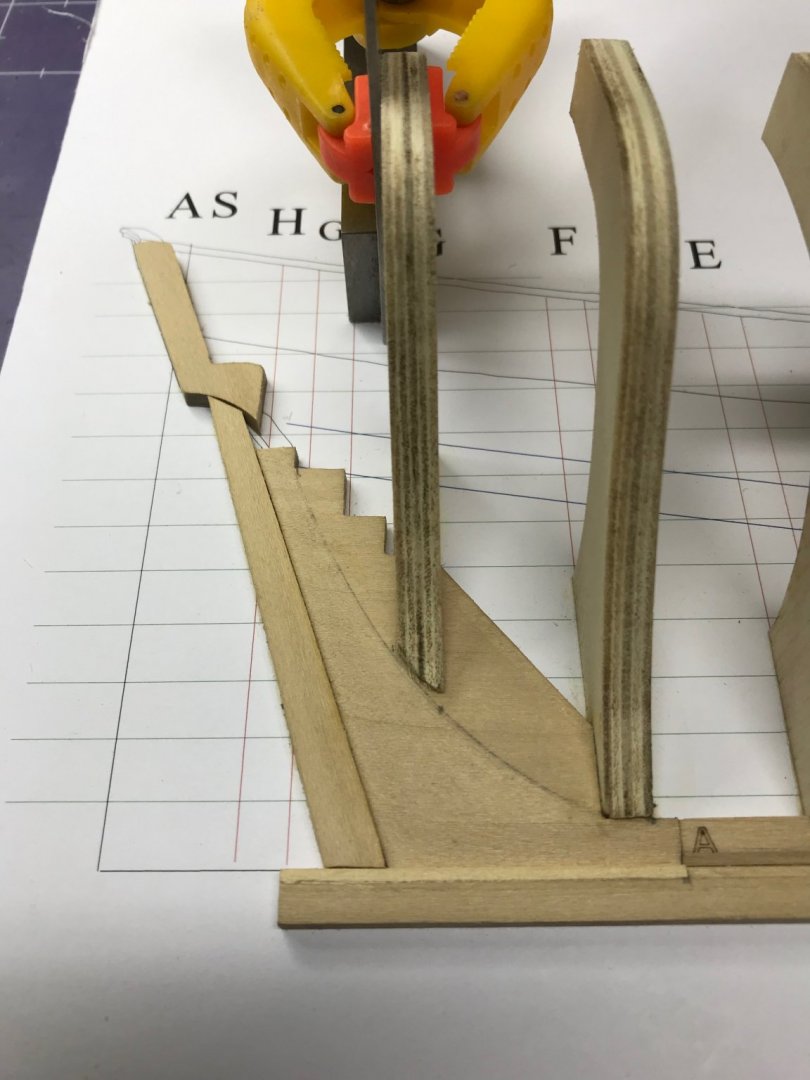
As per the instructions on Page 13, I glued "frames E through 4 to the keelson and the building board" and installed the spacers between them. That, as the instructions said, took some trimming and shimming to get right. One thing I'm a little concerned about is the snaggle-toothed aspect of the tops of the frames. I know fairing of the hull is critical and the bottoms of the frames, adjacent to the keel rabbet is fairly true, but the tops look different from Toni's pictures and look like they're going to require some surgery to get right. The next job is drawing the bearding line and then tapering the deadwood to accept the planks as they meet the sternpost. I "temporarily installed the deadwood and Frames G and H." Then I made a mark on the forward lower edge of the frames to define the bearding line. Using a French curve, I drew the bearding line. You might notice two lines in the picture above. That's because the written instructions say to make the marks and draw the lines to define the curve from the forward bottom edges of frames G and H. Here on MSW, Toni recommended making another mark at the bottom of Frame F, giving three points to define the curve. I did it both ways to see what would happen and it didn't make a nickel's difference. The deadwood has to be one plank thickness thinner at the sternpost and the keel than it is at the bearding line. It's a very subtle change. The deadwood is 0.127" thick. That thickness needs to be reduced by the thickness of the planks: 0.035". That means the final thickness will be 0.092" at the keel and sternpost, but will increase upward and forward to the original 0.127" thickness at the bearding line. To make sure I didn't take off too much wood, I marked the plank thickness on the bottom and stern of the deadwood. Then I started carving. I've used only hand tools up to this point, but I did use my Dremel with a sanding burr to do this work. I tried to get a good picture of the rabbet at the deadwood and the keel to show how this looks. Once the carving is done, the deadwood, sternpost and L-shaped piece are glued to the board. And then Frames F and G have to be installed. The bottom of Frame G has to be tapered to conform with the bearding line. That's it for today. Pretty good progress, I think. Dan


.JPG.4e03920ddf5053efb06de92eb53719c0.JPG)
.JPG.884c8908c3e06b677cbfb021956ad8f7.JPG)
.JPG.49576feb882119ccad3f3d878dd72e8d.JPG)


.JPG.c6abe452a32e916bb79f31989db8f284.JPG)
.JPG.dda52e218872b32b9a77a7730168fb69.JPG)
.JPG.d18afe379ecaa90cad8fcec02fbaa5de.JPG)

.JPG.dfa85e0d107e48a26dce567ab139f004.JPG)

.JPG.c27194cd184b782166702e7abfd90428.JPG)
.JPG.267dad0f9d0f5b00689fa1a052d117b7.JPG)
.JPG.c2e2071f1149c2fc34aaab0c330ab4d4.JPG)

.JPG.6237238af38475823a3f00e727f03d19.JPG)
.JPG.0fd11abcfaa90adf7355aba0dbdff504.JPG)
.JPG.f24908b8a88d7a12200cae9719373e7f.JPG)
.JPG.1af147f4102f3b7515259f41a2df69bc.JPG)
.JPG.24981b6686f69ccead5d6b0f1b92184c.JPG)
.JPG.b4351c0dcffacda50f5b244c0584e398.JPG)
.JPG.5c1216c16e5851d1e1802245a01bbc96.JPG)
.JPG.3221a775db834074a8ff19c97980b997.JPG)
.JPG.f3739b03e159cd7077d1a98c077444d0.JPG)
.JPG.15a045f26897fd661ac6f7517e7cbe55.JPG)

.JPG.ffa2af997d761299b2580c3c5cdcdc6a.JPG)