HOLIDAY DONATION DRIVE - SUPPORT MSW - DO YOUR PART TO KEEP THIS GREAT FORUM GOING! (Only 75 donations so far out of 49,000 members - C'mon guys!)
×


_SalD_
-
Posts
840 -
Joined
-
Last visited
Content Type
Profiles
Forums
Gallery
Events
Everything posted by _SalD_
-
 Thanks Augie, I've looked through your build of the Syren and it's excellent. I will be referring to it as I go.
 -
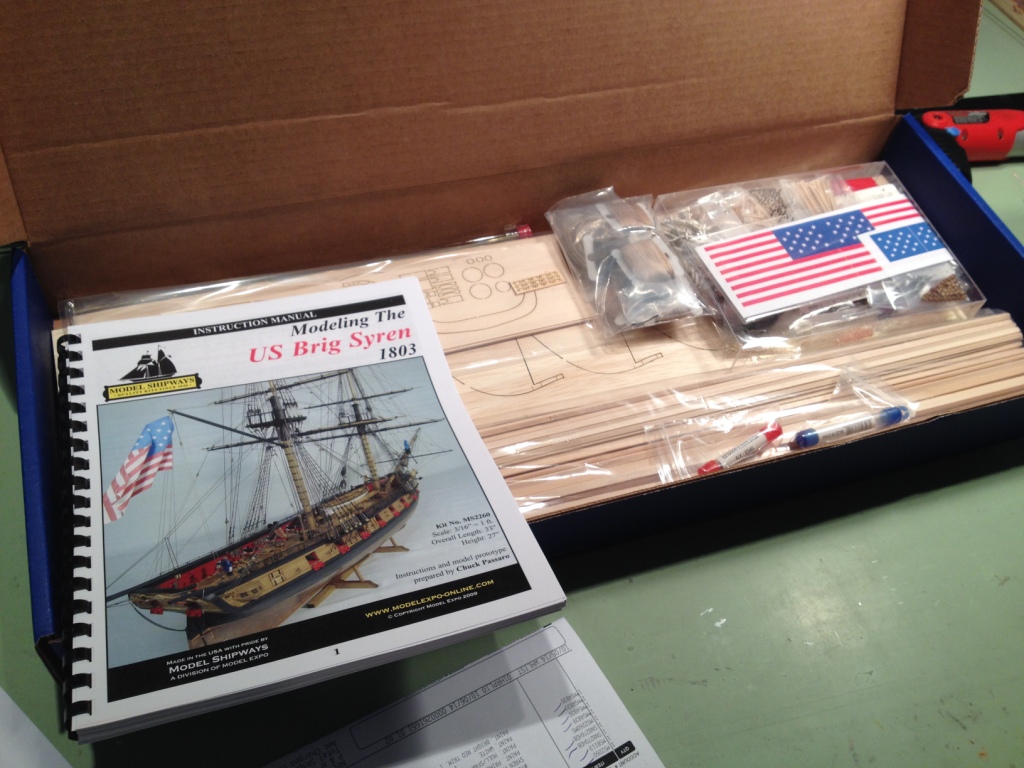
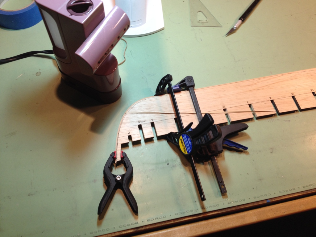
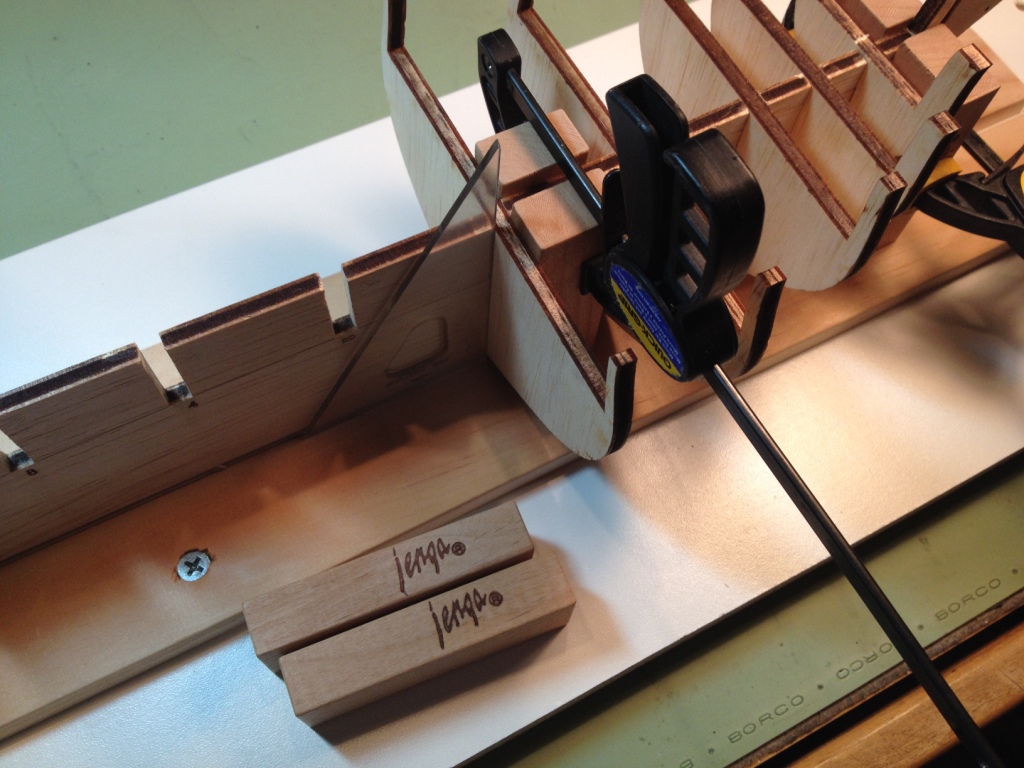
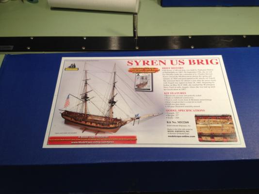
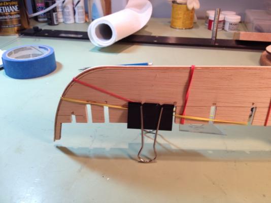
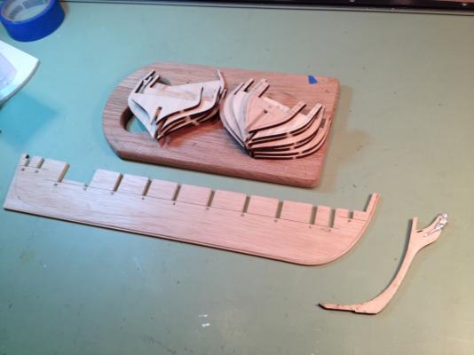
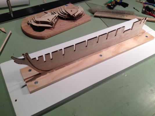
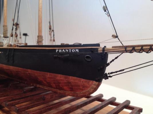
Hello all. This will be my second wooden ship, and build log, that I will be attempting. The first ship I built was Model Shipways’ Phantom which I found to be most enjoyable, so much so that I thought I’d try it again. For my second build I wanted to try a POB being that the Phantom was a solid hull kit. I looked at a number of kits and finally decided on Model Shipways’ U.S. Brig Syren. Although this kit may be a little advanced for me I chose it for a few reasons. First it’s a POB kit, second it comes with an excellent instruction manual by Chuck Passaro that pretty much gives me a step by step guide on how to build the ship and, last but not least, there are a number of excellent build logs here on MSW of the Syren that I can study. I wasn't going to start this kit until next month in order to finish up some chores around the house but the kit came and it was just sitting on the work bench calling my name and having an addictive personality I couldn't resist. So I opened the kit and took inventory. Everything was there except for some of the belaying pins and the ships wheel was broken. I sent a replacement parts form to Model Expo. Mandatory photo of the box and inventory. The Bulkhead Former was removed and checked for straightness. Not bad. Steam bend (used a little travel steamer) the rabbet strip around the BF and let it sit over night, then glued it into position. First small faux pas was to use the clamp at the top of the stem to hold the rabbet. With the basswood being wet and soft the clamp compressed the rabbet strip down to about half its thickness. Carved the rabbet along the BF, tapered the stem knee for the figurehead and removed the bulkheads (very carefully) and filed down the slots. Glued the stem knee and keel onto the BF and made up a keel clamp with a scrap piece of white particle board shelving and pine strips. I also test fit the bulkhead onto the BF and found that Jenga blocks work very nicely to square up the bulkheads.


- 659 replies
-
- 15
-

-
- syren
- model shipways
- (and 1 more)
-
Chris, Russ, Wayne, Brian, Tom: thank you all for the continued support and kind words. Patrick, thank you. It’s nice to hear from you and I’m glad you were following along. I hope you are doing well. For my next build I wanted to try a POB to give planking a try. I had given it a lot of thought and decided it’s time to leave the swallow end, take the swimmies off and jump into the deep end of the pool so I ordered the Syren by Model Shipways. I hope it’s not too big a leap but I figured with ‘mother’ Passaro watching over me I’d have a better chance of staying afloat. We’ll see. Best regards to you all,
-
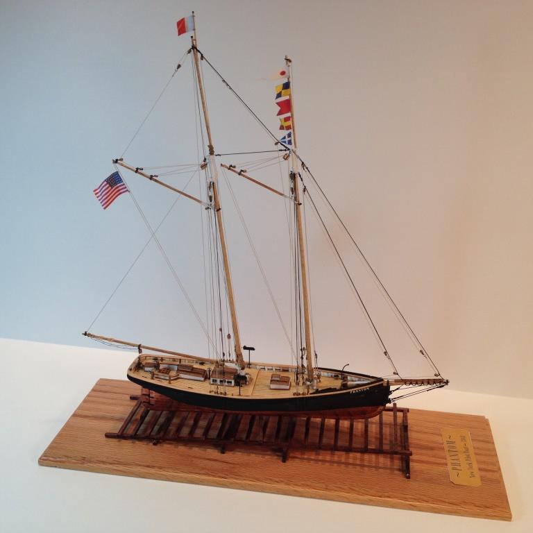
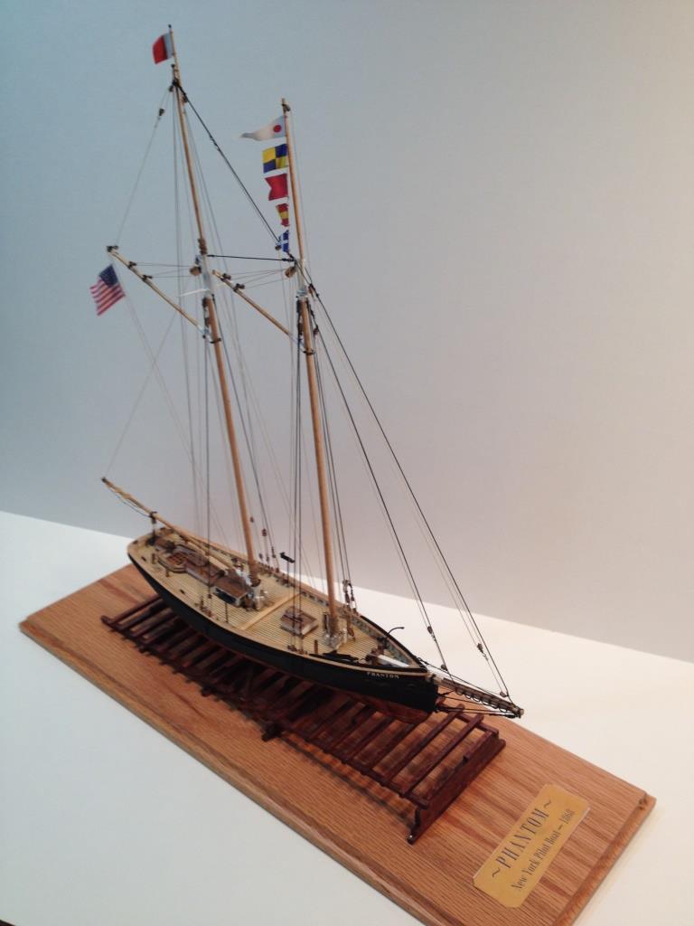
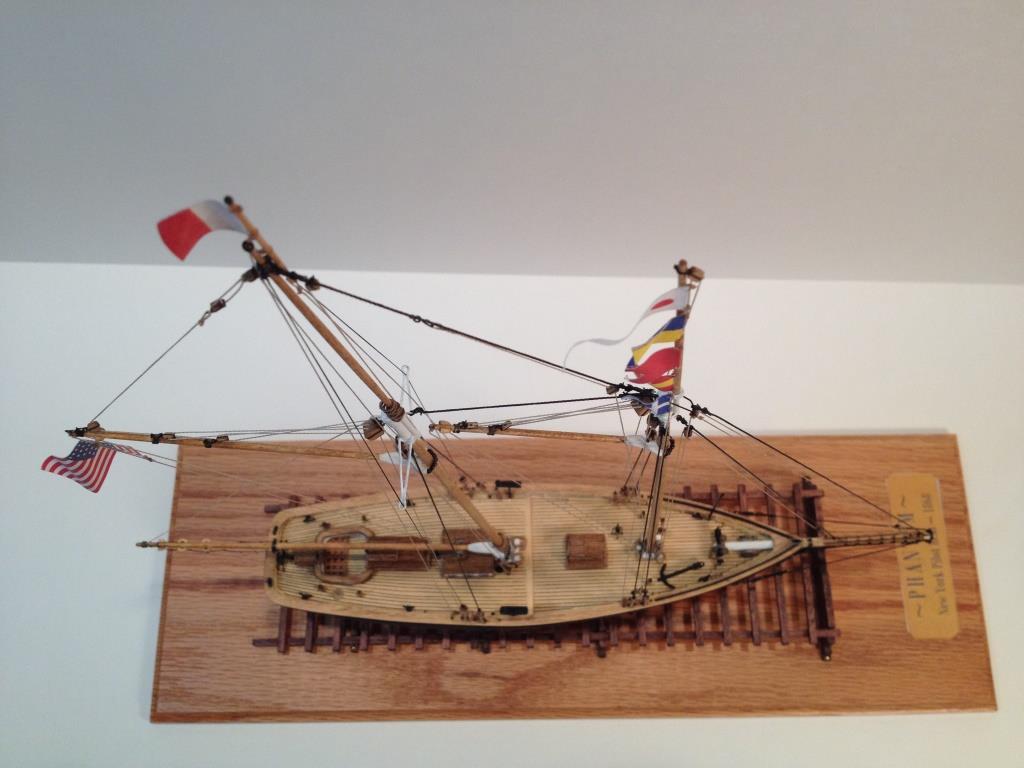
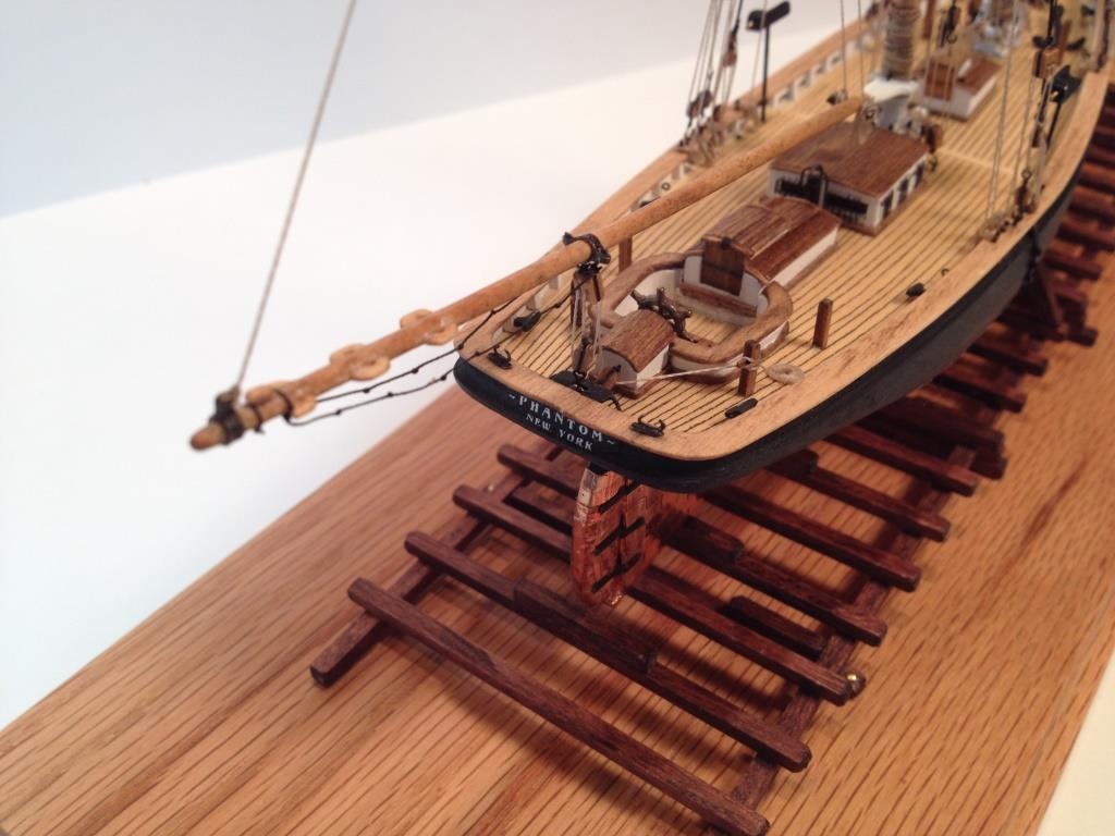
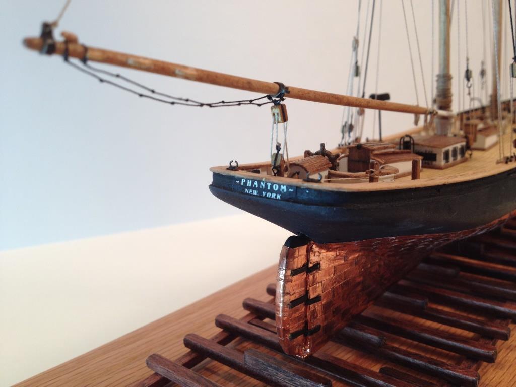
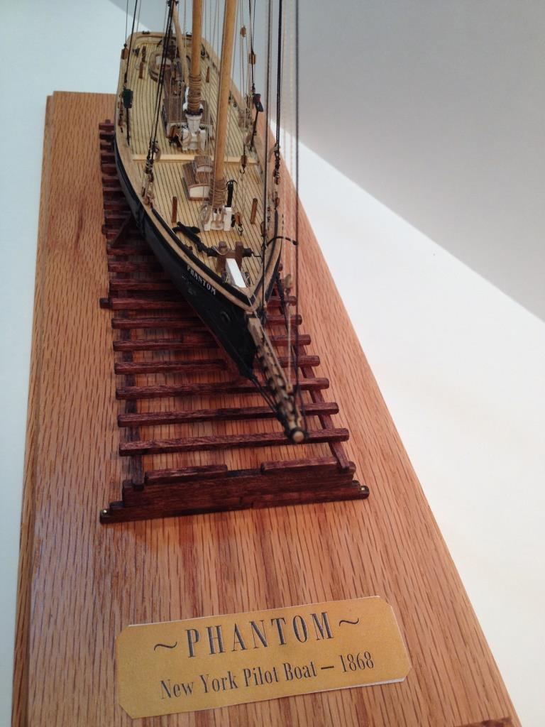
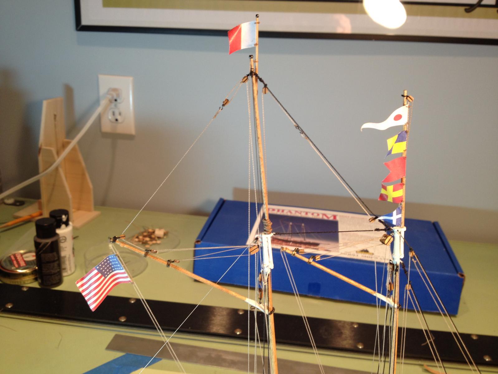
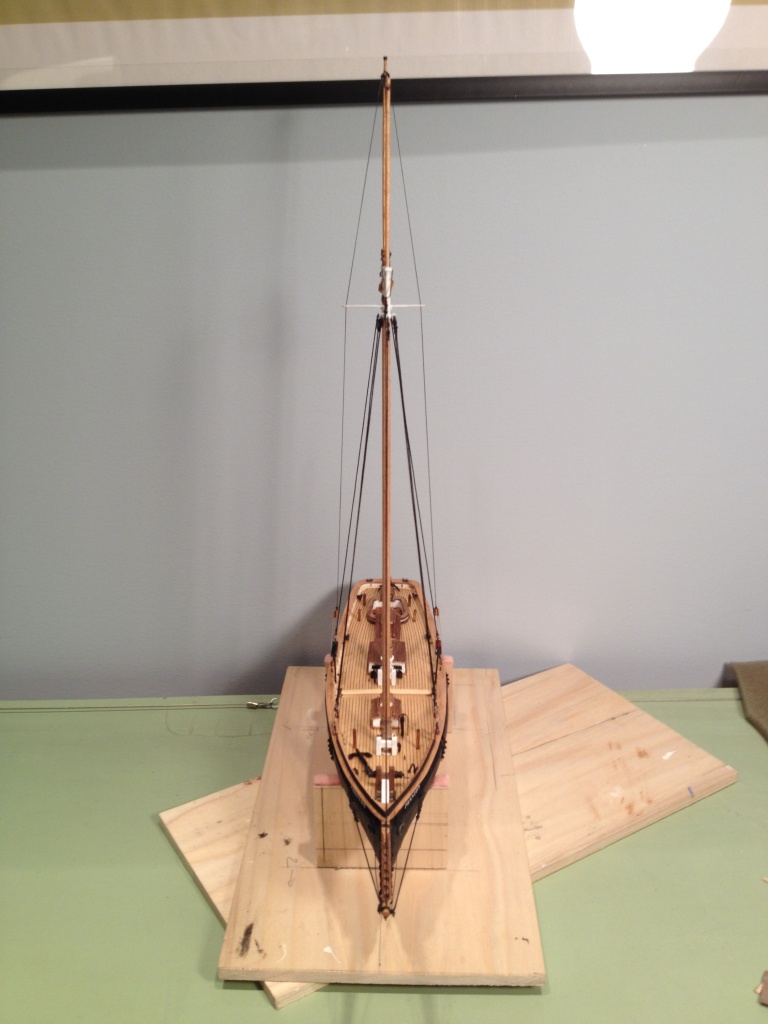
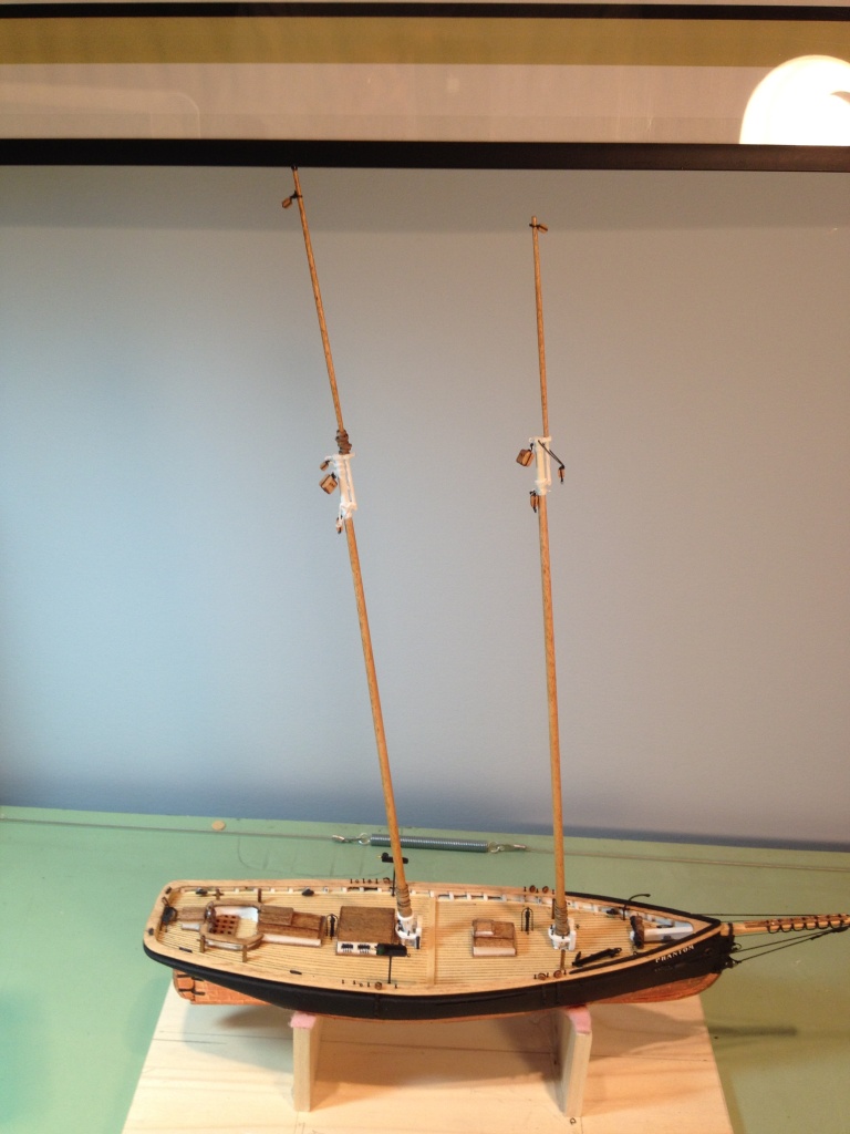
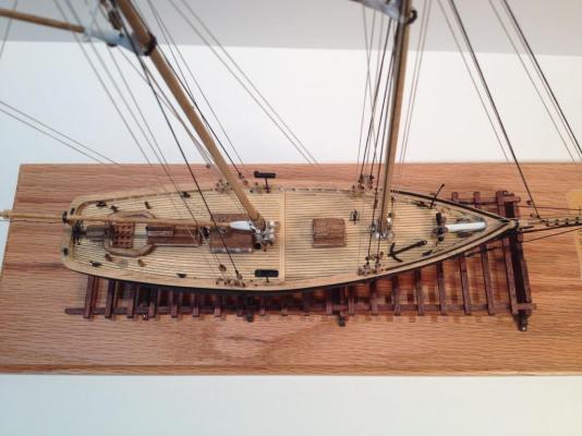
Finito!! I have finished the display base and have mounted the ship and launching ways. I made a temporary name plaque and just need to have a final one engraved. Although I'm excited that I've finally finished the ship and pleased with the way it came out I'm going to miss working on her. Deck is a little too clean, need to throw some more rope coils on the deck And now for the acknowledgements. I would like to thank Model Expo & Model Shipways for putting together a great kit that has been most enjoyable to build. The quality and quantity of material was first-rate. I think I only needed to fabricate four or five eye bolts. There were more than enough blocks, plenty of copper tape, plenty of standing rigging and just enough running rigging (could have used a little more to make some rope coils with). All in all I am very pleased that I chose this kit for my first build. The only issue I had, and this is not a fault of Model Shipways, was the instruction manual that came with it. If not for the practicum by Chuck Passaro, that supplements the kit’s instructions, this ship would have looked a lot different and would have taken me much longer to build. For that I am most grateful would like to thank Mr. Passaro for his fine practicum. I would like to thank all my followers and fellow Phantom builders for taking the time to view my build log. I hope this log will help others as past builds have helped me. I would also like to thank everyone for their help and comments and for everyone’s ‘likes’. Last but not least I would like to thank Model Ship World for hosting a great site. It’s truly amazing the expertise, knowledge and craftsmanship that can be found on this site. I've learned a great deal by reading other peoples build logs and hope to use this knowledge on my next ship. And on that note, good night and may God bless.


- 139 replies
-
- 11
-
-
- phantom
- model shipways
- (and 1 more)
-
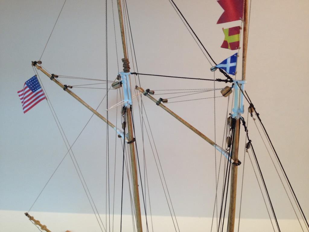
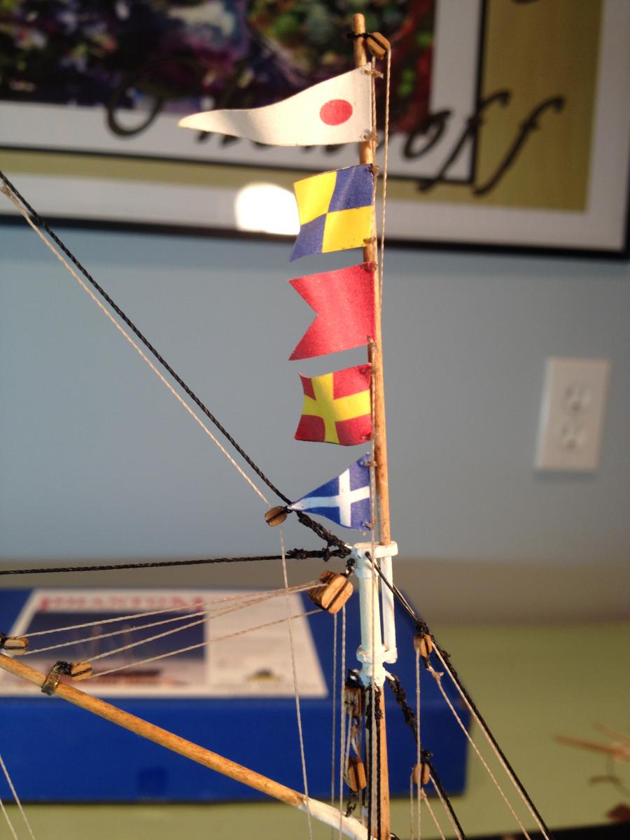
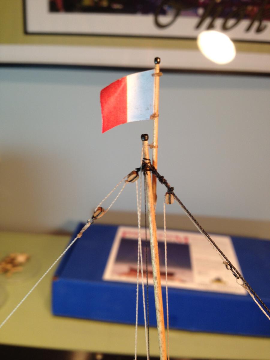
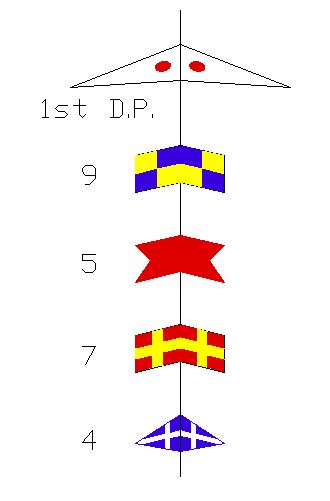
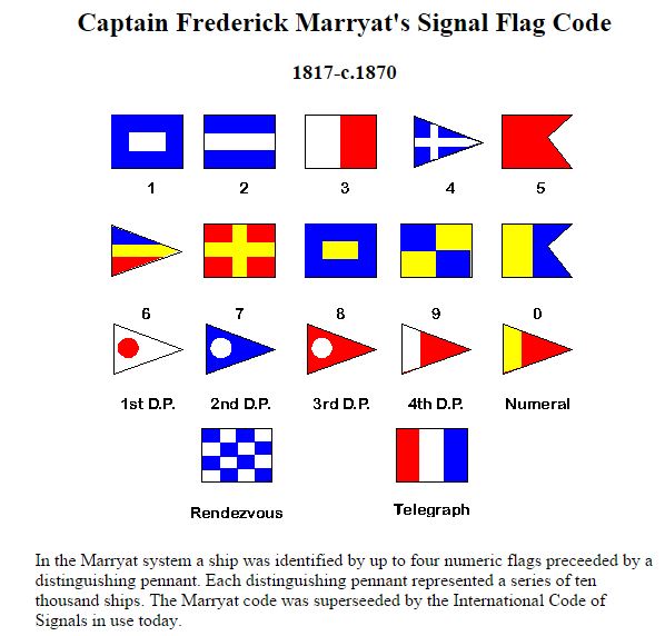
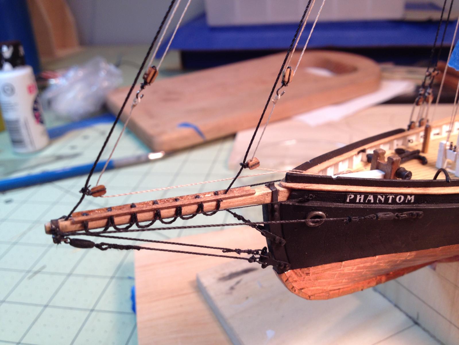
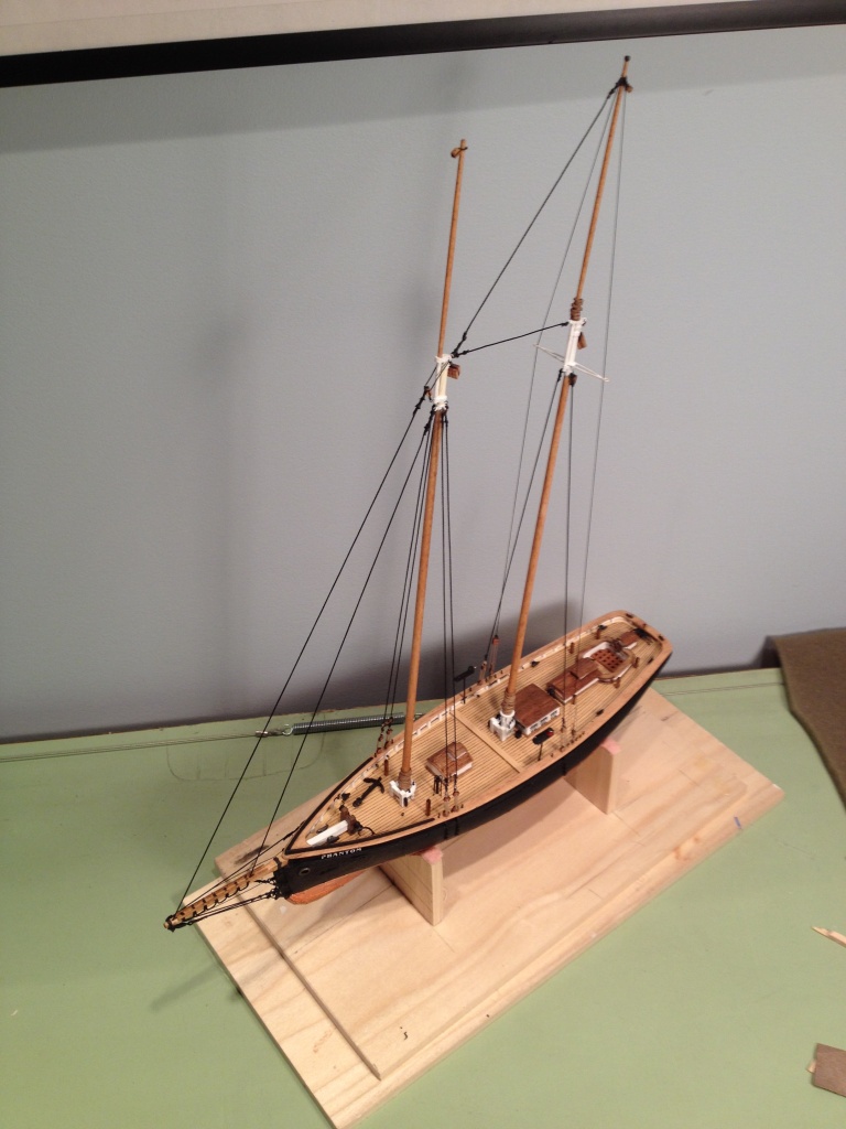
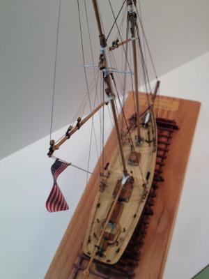
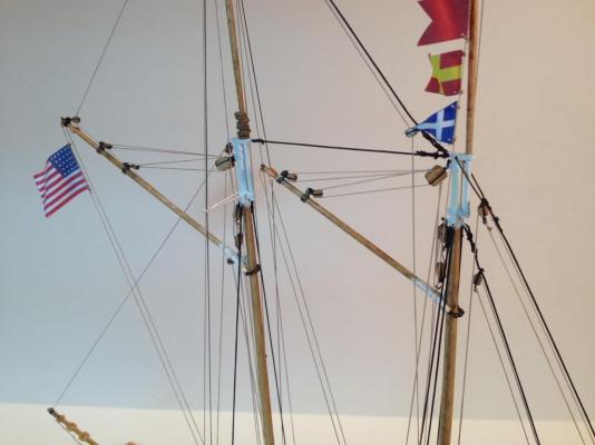
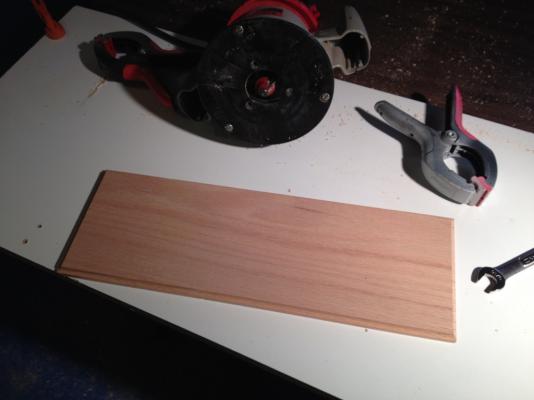
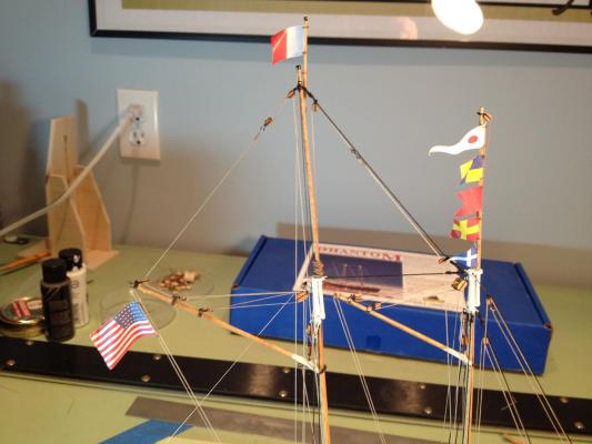
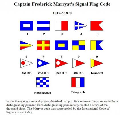
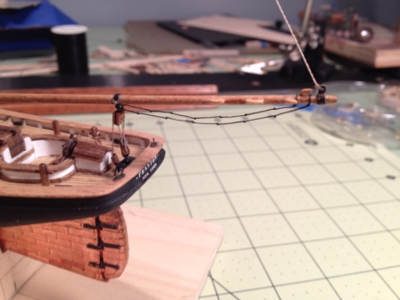
The rigging of the flag halliards is complete. I decided to use the American flag and the 'pilot’s on board' signal flag that came in the practicum but not the number flags. I did a little research into signal flags of the period and found in Captain Marryat’s Code of Signals, dated 1847, Part III, under merchant vessels that there is a listing for the name ‘Phantom’ with the corresponding numbers of 9574. I used these numbered flags along with the First Distinguishing Pendant and seized them to the flag halliard. Before printing any of the flags I reduced their overall size by 20% of what was in the practicum. Although they may not be dimensionally accurate I didn't want them to stand out so much that they would take away from the ship itself. The ship is complete and the only remaining task is to mount it on the launching ways and a display base. I made a base from a piece of oak that I purchased at Home Depot and just need to give it a few coats of polyurethane.

- 139 replies
-
- 4
-
-
- phantom
- model shipways
- (and 1 more)
-
Thanks again Russ and thank you for following my build.
-
After doing a little reading on naval signal flags I've decided to use the tenth edition of Captain Marryat’s Code of Signals, dated 1847, for the flags I’ll use for ‘Phantom’. In part III of this code under merchant vessels there is a listing for the name ‘Phantom’ with the corresponding numbers of 9574. I will use these numbered flags along with the First Distinguishing Pendant above them all, if I interpret the code correctly. Although the International Code of Signals was already in use (1855 to present) at the time the Phantom was put into service (1868), I decided to use Captain Marryat’s code for a couple of reasons. First, because his code was still in use up until the late 1870’s with the last documented edition being printed around 1879. Secondly, the Captain of this Phantom is an old sea dog who’s been sailing for what seems like an eternity and as he nears the end of his illustrious career the powers-to-be keep changing the codes for no apparent reason. For the better part of forty years everything was fine with the old code but then some intellectuals decide to justify their employment by coming up with a new “improved” code that no one can understand, except lawyers. And being a frugal man, having handmade his one and only set of signal flags many years ago, he’ll be damned if he’s going to spend money on a new set of flags or spend the time learning the new code so close to retirement. Not wanting to rush his life along or anything, but he’s counting the days to when he retires and anchors his houseboat in the Keys, sipping pina coladas (actually scotch, single malt, neat) on the poop deck. But I digress….. Here are the flags I will be using.

-
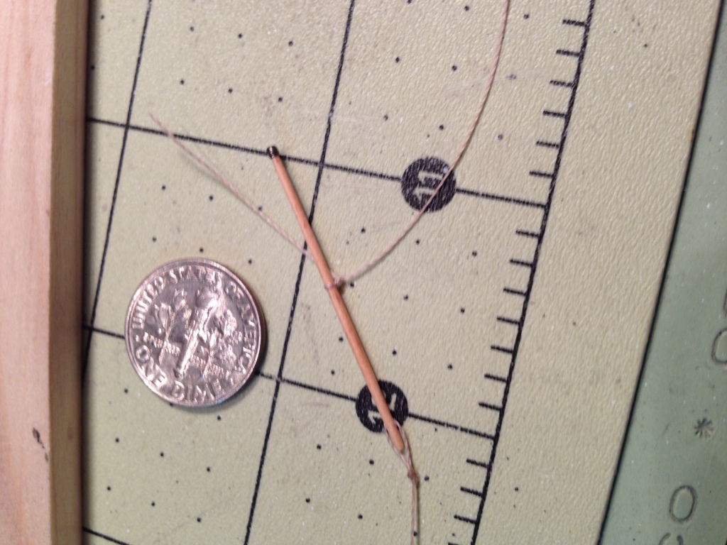
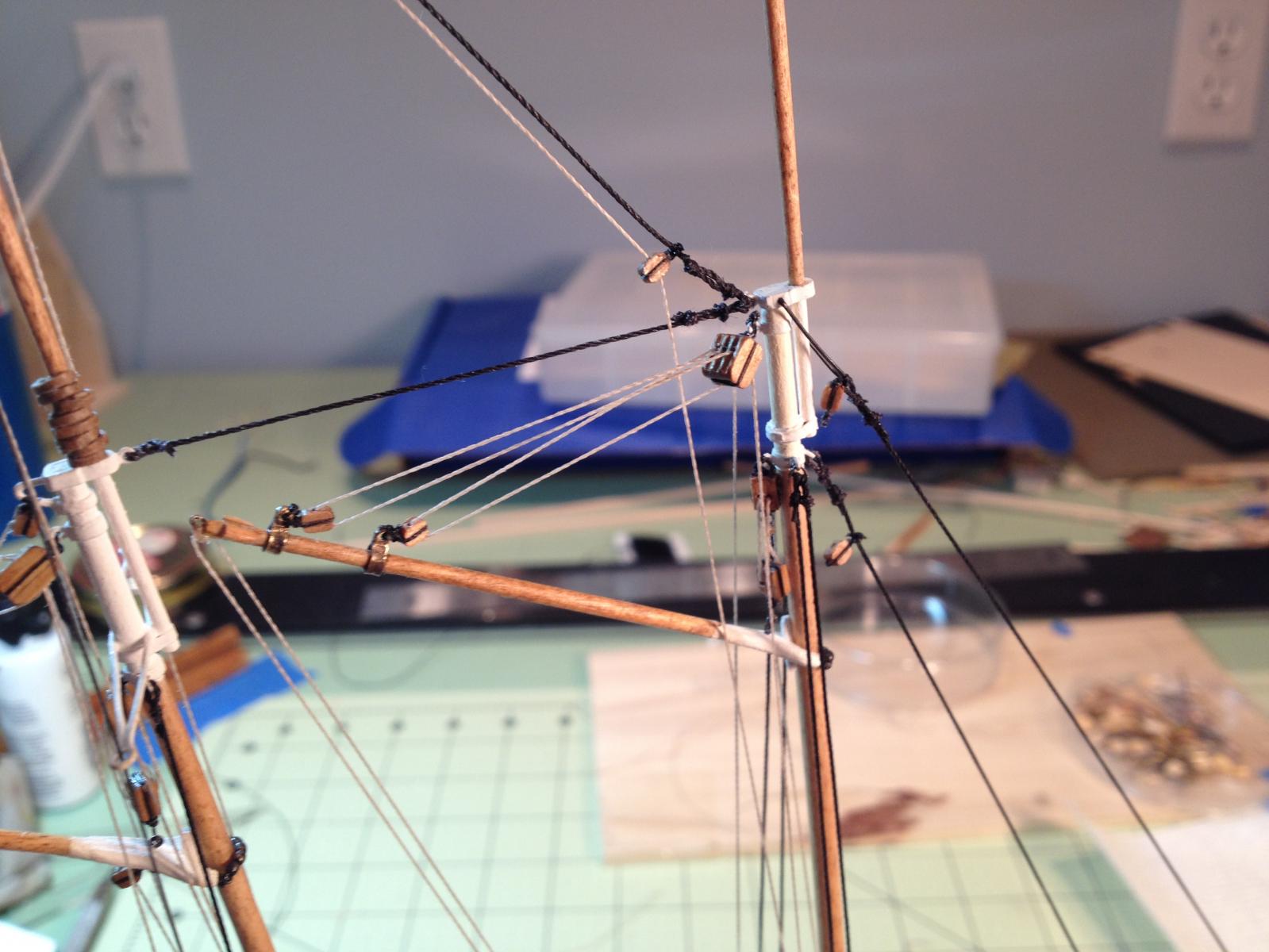
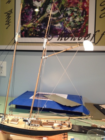
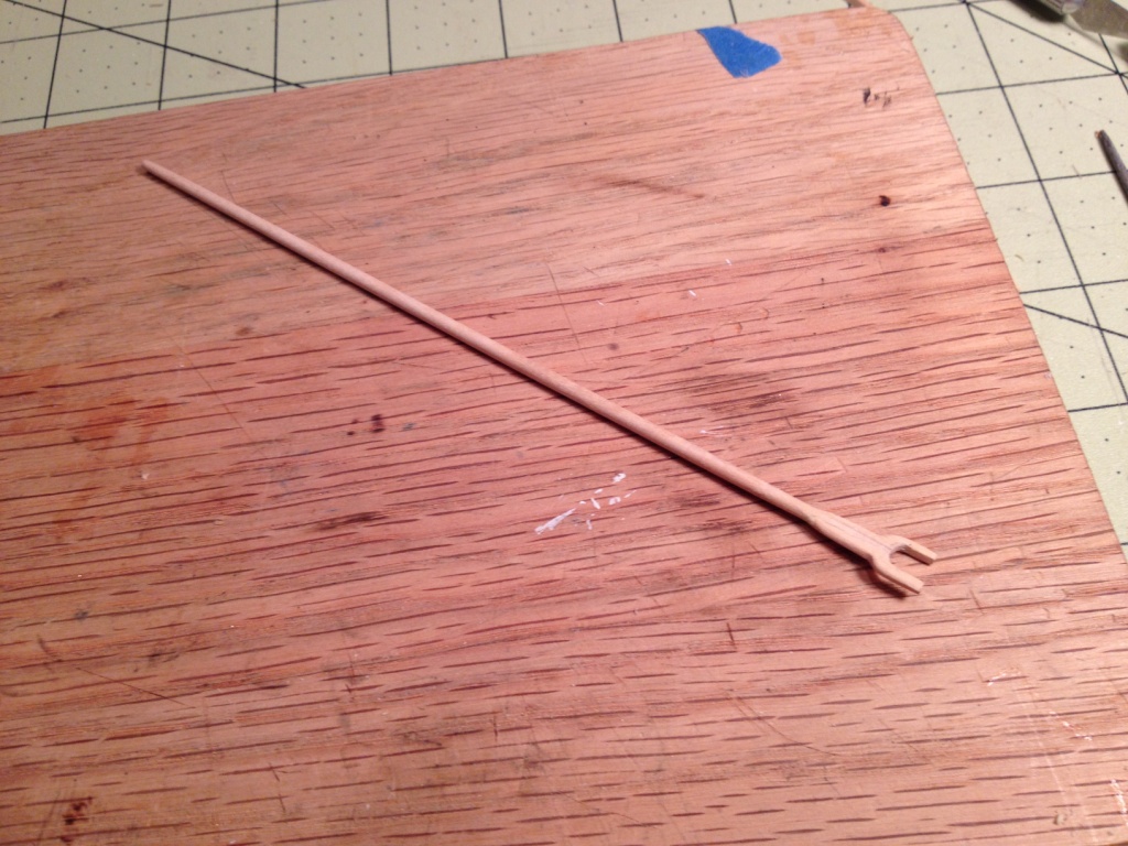
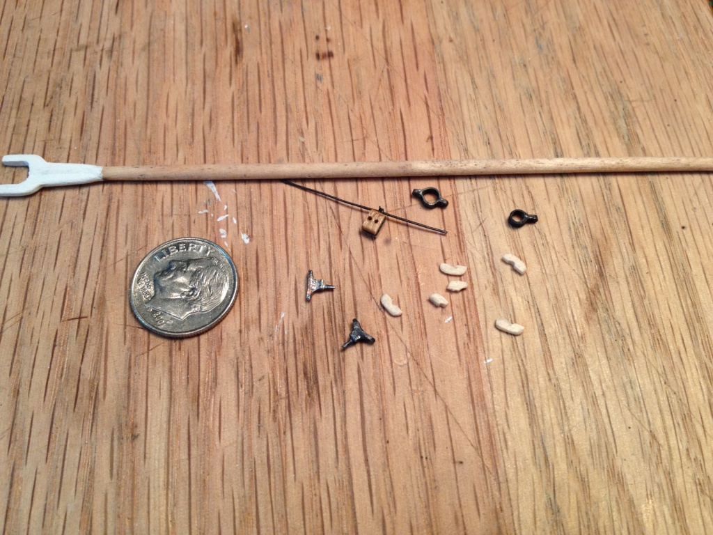
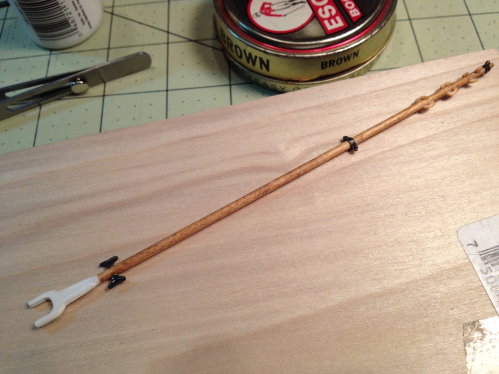
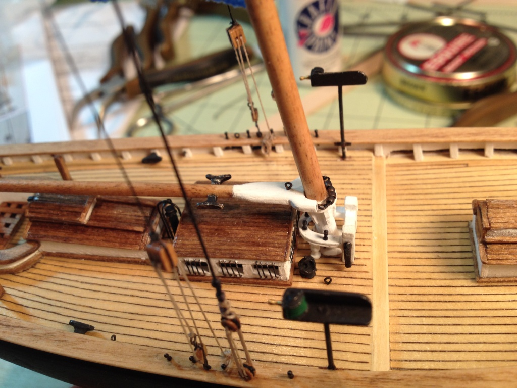
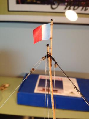
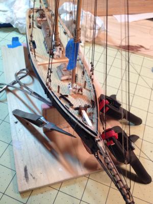
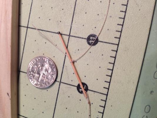
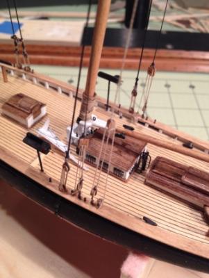
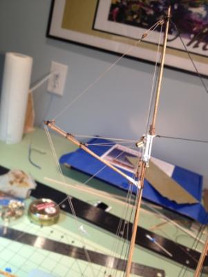
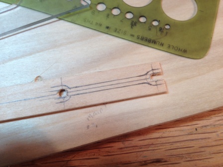
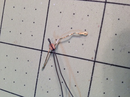
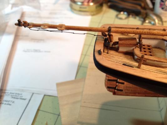
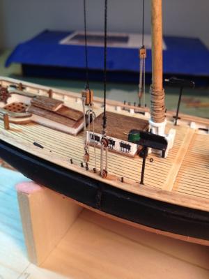
I started studying the layout of the Staysail and Jib Halliards with their corresponding downhauls and noticed the falls for the Halliards are to be belayed to the fore fife rail. However there aren’t enough belaying pins in the fife rail to tie these lines off. To remedy this I drilled two additional holes in the rail and added two new pins. The appropriate blocks were tied to the Fore and Jib Stays and the rigging was completed as detailed in the practicum. Rigging the Staysail and Jib Halliard I also started work on the signal flag that is rigged to the top of the main topmast. For this flag stave I used a toothpick and filed it down to the appropriate thickness. Added a parrel bead and tied the tan rigging line to it. I also drilled the hole at the top of the main topmast for this rigging line. Drilling this hole was a little nerve racking because I didn’t want to screw up the mast now that I was so close to finishing. I wish I had remembered to do this while making the masts. All went well however.


- 139 replies
-
- 3
-
-
- phantom
- model shipways
- (and 1 more)
-
I'd like to thank everyone for there input and it appears I have some reading to do. Wayne, those are great references I'll let you know what I come up with. Thanks
-
I’m nearing the completion of my model ship kit of the ‘Phantom’ and would like to add nautical signal flags on the flag halliard for the ships name and home port. After doing some extensive research (3 or 4 Google searches) I've learned that a four flag signal usually designates the name of the ship and where it’s from. What I can’t find is how you go about arranging the flags to say ‘Phantom of New York’. If anyone can tell me what four flags to use or if it's even possible I would appreciate it. Thanks ps If the name isn't possible any suggestions will be considered, just keep them PG-13. Thanks again
-
Thanks Russ, Things are moving quicker now. Stropping blocks is a lot easier and I’m getting pretty efficient at tying knots with a tweezers. Not quite ready for surgery but I could probably play a mean game of OPERATION now. And where have angled tweezers been all my life, those things are great! I finished the Gaff for the foremast and rigged it to the mast. The rigging was very similar to the Main Gaff. I tried to set the gaffs at the same distance below the mastheads and at the same angle. I am in a bit of a quandary. I'm at a point with this kit where I don’t have much more to do and there is a strong temptation to power through all the remaining tasks for the satisfaction of completing it. But then there is another feeling of dismay that this build will soon be over and I’ll have nothing to do but annoy the Admiral. I could never understand why some people had two or three unopened kits on their shelves, I’m starting to now. I’ll just need to approach the Admiral diplomatically about buying a new kit; “What will it be, a new model or more sex?” ...... I’ll let you know what kit I get.

- 139 replies
-
- 3
-
-
- phantom
- model shipways
- (and 1 more)
-
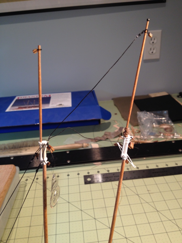
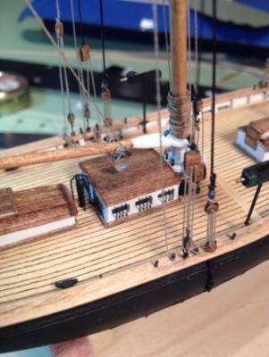
Main Boom and Gaff I finished the Main Boom rigging by running the topping lift and the Main Sheet Tackle. The installation of these lines was easy enough, so I thought, until I realized I ran the topping lift line through the single block at the top of the Main Top Mast meant for the Topsail Halliard instead of the block at the mast head. Fortunately it was an easy fix since the line was much longer than it needed to be. Main Sheet Tackle Topping Lift Tackle Rope coil Next I worked on the Main Gaff by making the jaws. I decided to make the jaws for the foresail gaff at the same time. The jaws were finished, the iron bands and the cleats were made and everything was assembled similar to the Main Boom. I followed the rigging steps as outlined in the practicum and although it was straight forward enough it seemed like it took me all day to rig this one boom. As I was working on this it boggled my mind how, on a real ship, all these line stay separate and don’t get all tangled let alone how do you remember which line goes with which sail. One thing I did discover after launching another block into the twilight zone while trying to put the stropping on it, was to thread a small piece of wire through the holes so if it did take off I’d have a better chance of finding it.

- 139 replies
-
- 5
-
-
- phantom
- model shipways
- (and 1 more)
-
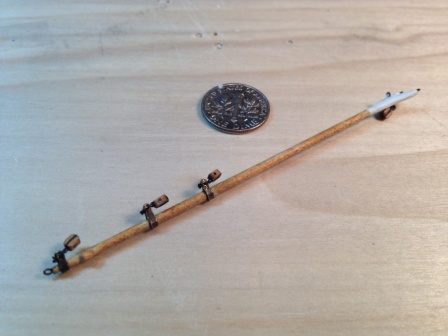
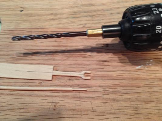
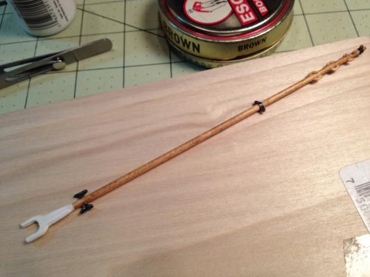
The Main Boom I started this task by shaping the 6” long dowel that was provided with the kit. I did this by chucking it into my electric drill and shaped it with sand paper to its proper form, similar to how the masts were done. Next I laid out the jaws for the boom on the 1/16”x1/2” wide stock that was provided with the kit. I decided to crave the jaws as one piece and then separate it into two halves. Prior to drawing the jaws on the wood I drilled a 5/32” diameter hole in the wood. This corresponded to the diameter of my mast and gave me a starting point to draw the jaws. Then using an x-acto knife with a number 11 blade, I removed a majority of the waste. I finished shaping the jaws by using an emery board. After I was satisfied with the shape of the jaws I carefully cut the piece in two. I then cut the end of the boom down to fit the jaw pieces. Next I made all the boom attachments. I made the iron bands from the brass strip that came with the kit, the wood stopper cleats were cut from a 1/32” thick sheet, the metal cleats are the ones that came with the kit. The metal cleats looked a bit large so I tried to reduce their size by filing. I think I should have kept filing and made them even a little smaller. I then assembled all the pieces. The double block for the Main Sheet Tackle was tied to a piece of 28 gauge wire which was formed into a ‘U’ shape and inserted through holes drill into each ear of the iron band. The boom was attached to the main mast with parral beads. I raided my daughter’s bead supplies again and found some brass beads (size #0) that were blackened and strung on thread between the two eye bolts on the jaws. Prior to attaching the boom I also tied the foot-ropes at the end of the boom as shown in the practicum. My 'OH SH*T' moment came while I was making the stopper cleats. The day before I had made the iron band for the Main Sheet Tackle and made a mental note that I needed to put the finish on the boom before gluing it on. Well, as I was making the wooded cleats, the next day, I told myself that I should glue these on before I put the finish on. So I glued them on. Needless to say while I was admiring my work and was so proud of how the cleats came out it dawned on me that I didn't have the iron band in place and needed to pull off all the cleats. Fortunately I used white glue and they hadn't set for too long. After that it was cocktail time and no more work for the day.


- 139 replies
-
- 2
-
-
- phantom
- model shipways
- (and 1 more)
-
Brian, Russ, Tom, thank you for checking out my work and the kind words. I would also like to thank everyone for the 'like this'
-
Brian, Just read through your building log. You're doing a great job. The planking, deck fixtures, and masts look terrific. As a first time builder myself I can appreciate the effort you're putting into it. Keep up the good work. By the way, have you read all those books?
-
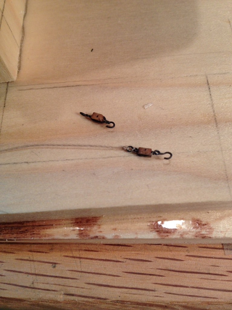
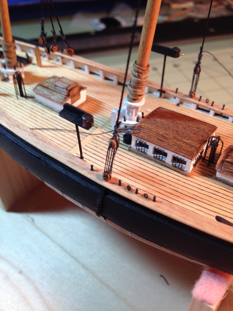
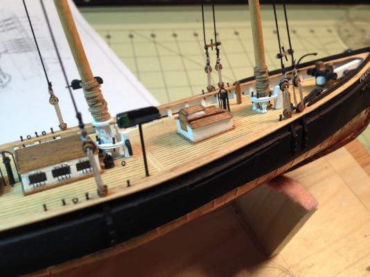
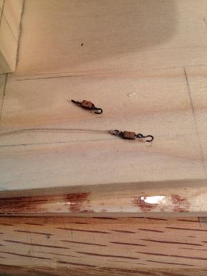
Lanyards and Main Topmast Backstays are complete. I wasn't sure how tight to make the shrouds but I didn't put too much tension in them. I had to play with the lines a little to get the deadeyes to line up but persistence prevailed. The Pin Rails with the belaying pin were also tied to the forward shrouds. I need to thank Modeler12 for his tip in one of his posts about applying some ca glue to the end of the lanyard that is inserted through the hole in the deadeye. It made threading the line much easier. I would also like to thank Wayne for his help with the proper way to rig the deadeyes. For the main topmast backstay rigging I started by stropping my block (pardon me if that’s not the correct terminology). I twisted some 30 gauge wire around the single sheave block forming an eyelet on the top and a hook on the bottom. This will be used with the running rigging on the backstay. I then tied the backstay line to the top of the main mast and threaded it down through the outrigger eyelet. Taking a measurement from the rigging plans I located the double block and tied it to the end of the backstay line. Once that was done it was a simple task to reeve the running rigging line through the blocks. One problem I ran into was that after rigging these lines you are suppose to tie it off to a belaying pin in the cap rail. Not knowing exactly how these pins would be used when I installed them I unfortunately placed them to far outboard on the rail so I had no room between the pin and the bulwarks to get the thread in. Fortunately the aft deck scupper was right there so I passed the line out through the scupper and held it in place so I could glue the line to the bulwarks right next to the pin and then brought the line up and around the top of the belaying pin. Then I tried my hand at making rope coils. I think I spend as much time on one coil as I did carving the hull. This one’s too big, this one’s too small, and this one’s unraveling. I never got one that was just right but close enough. I really enjoyed rigging these lines. With the rigging placed on the model I’m starting to get a better understanding of how they all work together. When looking at a fully rigged ship, model or real, it’s hard to visualize where all the lines go and how they work. By doing them one at a time you can see how they brace the masts and how by moving one point on one mast it affects the others. Very structural, I like that. One footnote, I hope there are extra single blocks that came with the kit. While trying to strop the wire around them I did launch a few across the room.


- 139 replies
-
- 6
-
-
- phantom
- model shipways
- (and 1 more)
-
Thanks again Wayne
-
Thanks Wayne. I do have a question. For the lanyards I have found two conflicting ways of doing them. One has the knot in the upper deadeye always starting on the right hand side of the deadeye (port or starboard) looking outboard. The other way has the knot starting on the left looking outboard. Is there a proper way of doing it or is either way okay, just be consistent?
-
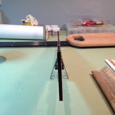
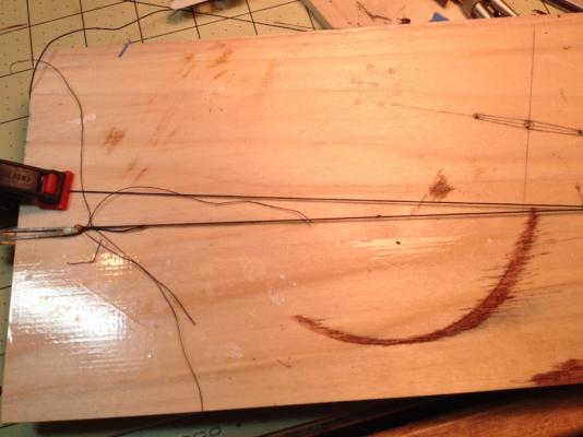
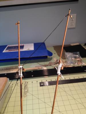
Working on the shrouds I'd like to start by begging forgiveness from all my followers as to how I did my shrouds. After hours of deliberation on how I was going to tie the shrouds, my practical nature prevailed and I ended up making the shrouds off the model. First I measured the distance from the eye bolt on the mast to the deadeye on the cap rail where the shroud would go between. From that dimension I subtracted the distance between the cap rail deadeye and the shroud deadeye taken from the rigging plans. This dimension I used to make a jig to tie the shrouds. A single pin was driven into a piece of wood corresponding to the eye bolt at the top of the shroud (can't see it in the picture). Two smaller pins were positioned at the calculated distance away from the top pin corresponding to the location of the deadeye. Two pins were used to keep the deadeye from rotating. I then place a deadeye on the two pins, held down with a hair clip, wrapped the shroud around it and seized the end. I then looped the thread around the upper pin and tied that end off. I made the four, foremast shrouds and then readjusted the length between the pins for the main mast shrouds. To attach the shrouds to the masts I made a small shackle for the two foremast shrouds and for the main mast I opened up the eye bolt and slipped the top loop of the shroud into it, then closed the eye back up. Please forgive me and I promise I’ll try tying the shrouds like I’m suppose to on my next model. Maybe they’ll be a little bigger next time. I then practiced tying the main mast lanyards before attempting the real thing. Using some sewing thread I tied both the port and starboard side lanyards in order to get a feel on how tight to make them and to practice tying off their ends. While doing this I came up with a simple way to help make sure the mast stayed plumb. Using my 45 degree triangle, I scribed a line bisecting the 90 degree angle and perpendicular to the hypotenuse. Oooou… algebra, “when will I ever use this stuff”… little did I know. I then measured the distance between the cap rails at the location of the mast. Dividing that distance in half I marked that distance on either side of the scribed line along the hypotenuse. Then laying the triangle up against the mast and with the two marks at the edge of the cap rail I could see if the mast was pulled to one side or the other.

- 139 replies
-
- 1
-
-
- phantom
- model shipways
- (and 1 more)
-
OUCH! Ulli sorry to hear about the hand. Hope everything heals okay. You just can't hire good help these days.
-
Ulli, Hello from a fellow Phantom builder. I hope you will enjoy building this kit as much as I am. It’s a challenge but with the help and advice from all the people on this site like Wayne, you should have no problems. I'm a bit ahead of you but I will be following your build with interest. Good luck,
-
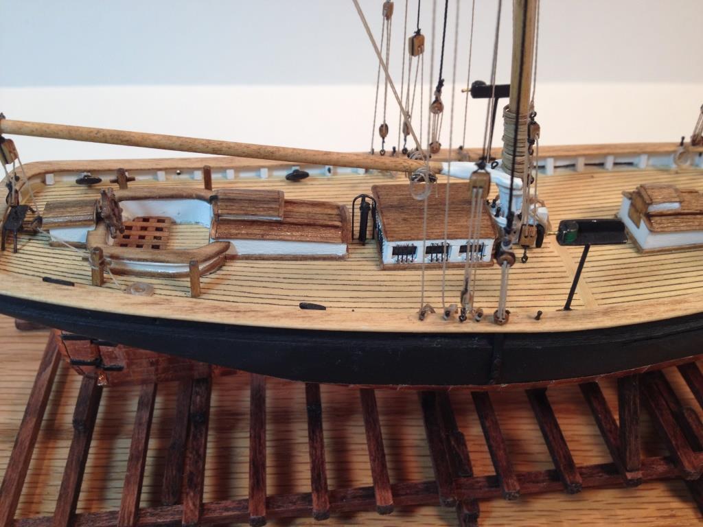
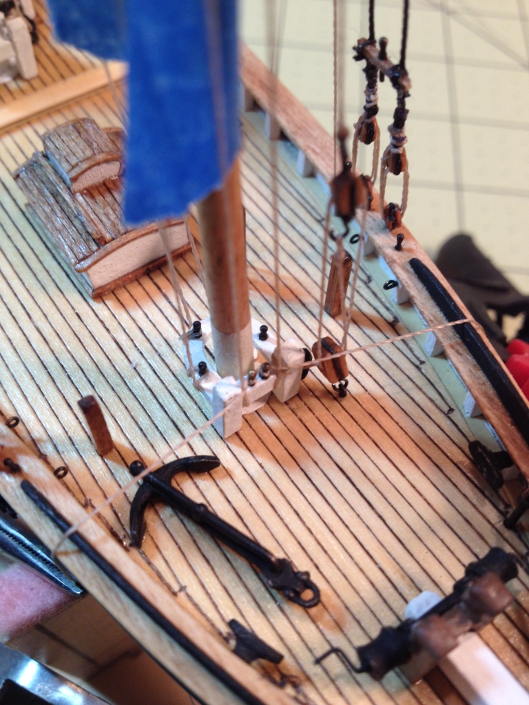
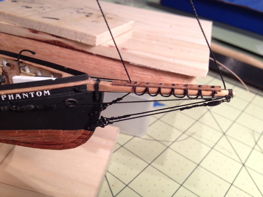
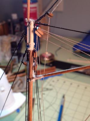
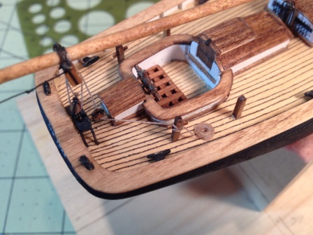
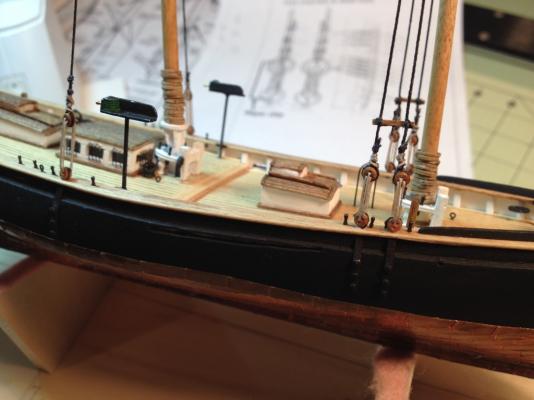
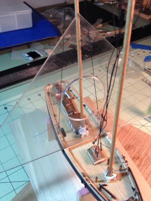
As in the practicum the first two lines I installed were the Fore Stay and the Jib Stay. I’m glad I didn’t glue in the Span Iron in place when I installed it because I found it easier to tie the Fore Stay with it swung up out of the way. After I tied the Jib stay I placed a couple drops of CA glue on the Span Iron at the mast cap. The next two lines I installed were the Main Topmast Stay and the Triatic Stay. I noticed that I would need to thread both of these heavy lines through the same eye bolt on the foremast mast cap and thought this might be difficult. What I did was, first I tied the Main Topmast Stay to the top of the main top mast, then, using a needle threader, I pulled the line through the eye bolt on the foremast mast cap leaving enough thread to rig the Triatic Stay also. I then cut the loop that was pulled through the eye bolt giving me the two ends of the Main Topmast Stay and the Triatic Stay. I then seized both ends of each line. Hope this makes sense, picture might help. A WORD OF CAUTION. For all my fellow Phantom builders who blindly follow directions such as myself (well, most of the time) . I started laying out the shrouds and I noticed that the Navigation Lights are going to interfere with the main mast shrouds. These lights were positioned as shown on Sheet 1 of 3 of the kit plans and as shown in the practicum. If you notice, the lights are shown on pages 19, 20, and 25 of the practicum positioned between the main mast shroud deadeye and the belaying pin, just like the plans. Then on page 26 a miracle happens and the lights are now fore of the belaying pin. Did I miss something? Anyway, I removed (carefully) the lights and moved them forward a bit. I’ll just need to cover up the two holes in the deck with a mop or bucket.

- 139 replies
-
- 1
-
-
- phantom
- model shipways
- (and 1 more)
-
Thanks, Russ
-
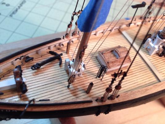
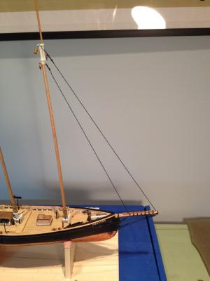
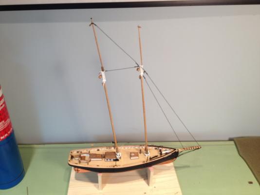
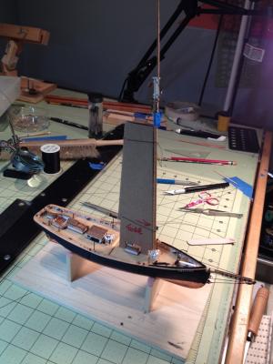
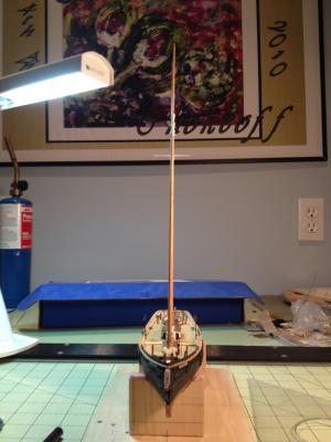
Stepping the masts After correcting my booboo on the mast hoops I glued the masts to the model. I decided to glue the masts in lieu of letting the rigging hold them for two reasons. One, when I drilled the mast holes in the deck I didn’t realize at the time that the dowel diameters would be reduced when shaping the masts, so consequentially the holes were a little big. The second reason was for my lack of experience at rigging. I realized (common sense prevailed) that there was no way I would be able to tie all those lines with the masts flopping around. I set the foremast first with the aid of a cardboard template, cut to the appropriate rake angle. I tied the mast to the template to hold it in the fore & aft position, and plumbed it by eye in the inboard-outboard direction. The blue tape on the mast is holding the mast hoops up out of the way. After the glue had dried over night I set the main mast. To set the correct rake angle and to hold this mast in position I tied a temporary string between the two masts where the Triatic Stay goes. I determined the length of this line by measuring it from the plans. I eye balled the mast for plumb in the inboard-outboard direction.

- 139 replies
-
- 2
-
-
- phantom
- model shipways
- (and 1 more)
-
Bart, thanks for looking at my build and for the kind words.