

kirill4
-
Posts
910 -
Joined
-
Last visited
Content Type
Profiles
Forums
Gallery
Events
Posts posted by kirill4
-
-
Good day Steve !
Oh! two years late !
Sorry! It just caught my eye when I looking throug pictures of Your build , consider delay with my comment it is mostly theoretical question now , of course it’s better not to change anything here and place the remaining gratings in the same way as those already installed... just consider this information into account for the future, by the way, yesterday I started looking for additional information on this issue... and while looking at the photos of the replica, Mayflower 2 noticed that these gratings were not installed there according to the classic way, so to speak!
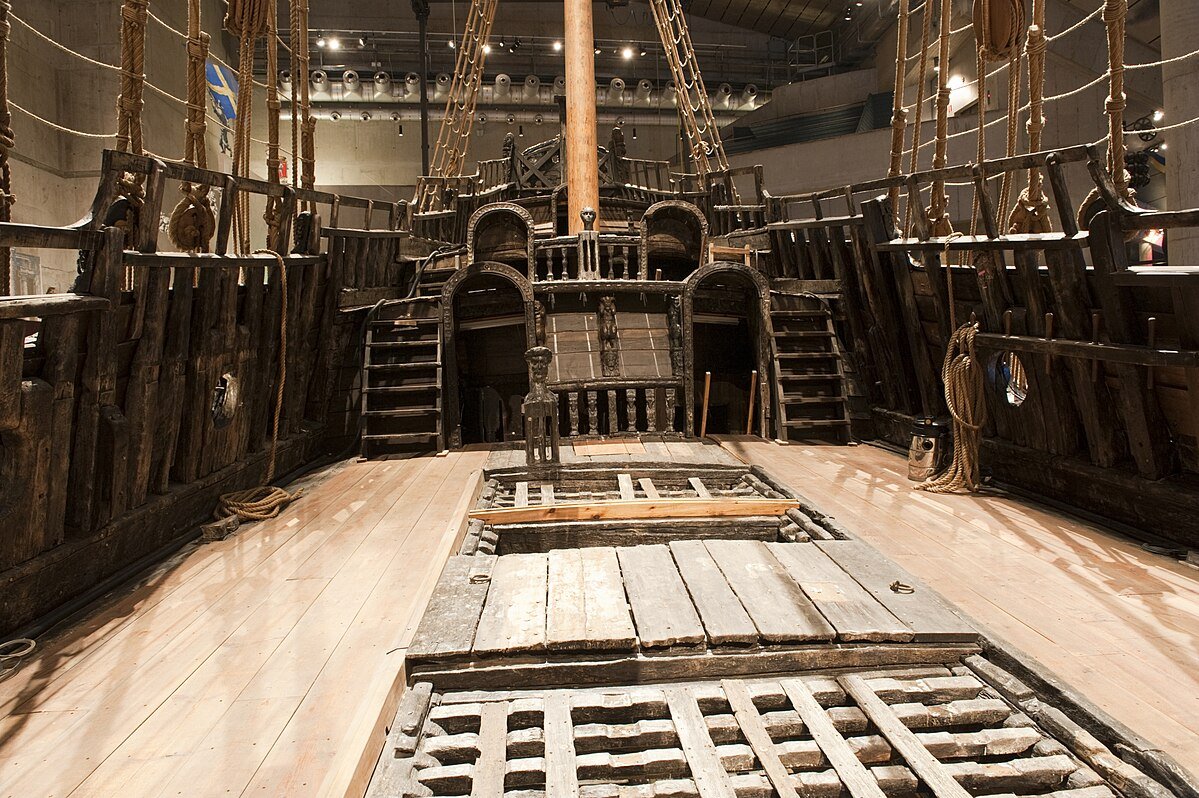
But this is a replica and it is quite likely that the builders considered this point not at all important but in general, as far as I can judge from the literature, or photos of original Vasa , or photographs of old original models - the battens of the deck's gratings are always located along the deck center line ... and placed above of the transverse elements (ledges) which lay perpendicular to the center line of the vessel.
Wish You all the Best and good luck with completion of this nice model!
Kirill
- Ryland Craze, 72Nova, Admiral Rick and 1 other
-
 4
4
-
Good day Steve,
Nice , clean wood work!
some minor remark, eye catcher -the top bars of the gratings should, as a rule
") , be located along the center plane, not across...
, be located along the center plane, not across...
Vasa's deck as example ....
All the best and M-Xmass!
Kirill
-
Good day Ondras!
Very fine and clean work! Such a great pleasure to look at it and to see how she is slowly growing up!
All the Best!
Kirill
Ps
I' m not an expert, but by visual impression, deck boat lashing looks a little bit too light and fragile . May be there is sence to use some set of 3 ropes or some more thick rope for that purpose/ to hold( secure) boat on deck?
-
Good day Bill,
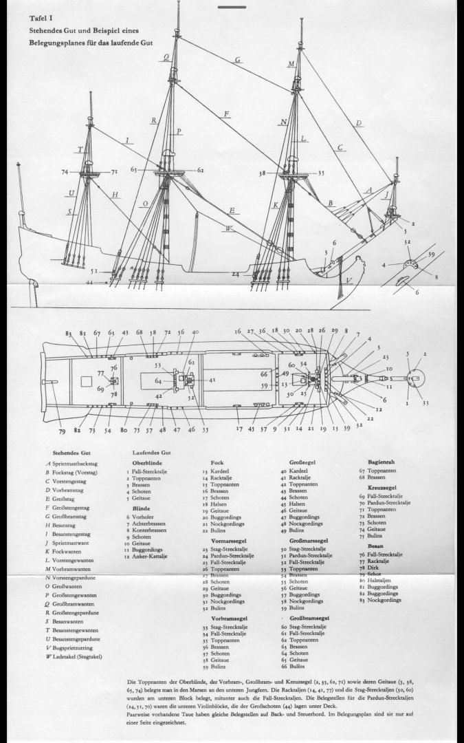
Oh, I see now... I m afraid that excel tables which I posted operates just common data based on European shipbuilding tradition depend on rigging period but don't give You specific details belong to spanish galleon exactly...
info You are looking for on the rope sizes used on standing and running rigging on SPANISH galleons between 1500-1800 , hm, it is quite a huge period when rules has been changed significantly ... I could guess You need to dig through the Spanish-speaking forums to find more specific details regarding your question. Maybe there is sense to narrowing the field of your research / one ship model of which You want to build?
ps
above Waldemar gave many useful links...
pps
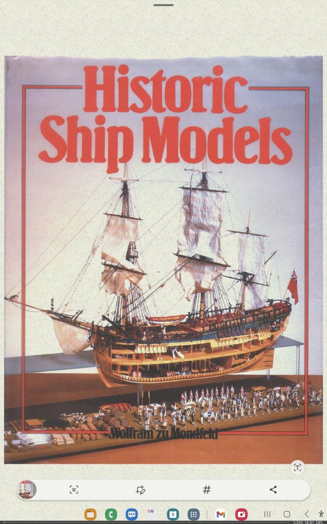
It seems to me that in order to competently and without excessive fanaticism equip an amateur model of a ship with rigging in accordance with the selected historical period, the information provided in the books and tables of RC Anderson, Mondfeld, and several other well-known authorities is quite sufficient, given that the above-mentioned excel tables were compiled taking into account the works of these authors... The Spanish school of shipbuilding of the 17th, 18th, 19th centuries, I believe, kept pace with the rest of the European continental schools and it is unlikely that there were any cardinal differences in the armament of ships with rigging that could be shown on the model, especially with regard to the sizes of running and standing rigging....
-
Good day Bill,
As seems to me ,there is not so big problem with it, how to find necessary ropes sizes for your galleon...I could recommend a few ways:
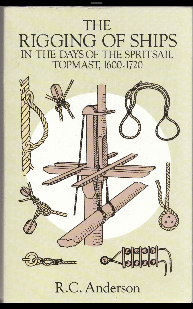
00. Book by RC Anderson where He gives all necessary XVI - XVII centuries rigging info
01. as far as I remember, on this forum, a few years ago I ve found very nice and handy excell tables made by one of ours colegues, tables which automaticaly calculated all necessary standing and rigging sizes of each rope You be need to rigg your galleon( and any other models as well) model... depends on period and rigging types and style
02. famous Mondfeld's book with nice tables regarding rigging and mast and spars sizes
03. Hoeckel 's book which looks like short version of RCAnderson book but containts all necessary data as well...
By my small experience , these sources could/ will provide You all necessary info( in general at least) for rigging your galleon model in the best simplified but accurate way...

Period Ship Scale Tables_2305250745__46.xlsx
Rigging - size of rope and blocks - Final.xls Period Ship Scale Tables.xls
-
Good day Ondras!
Greetings! Excellent work! It is always a great pleasure to watch how the model becomes more beautiful as it acquires details! And will you install bolsters, or are they already installed and hidden under the shrouds?
All the Best!
Kirill
- FriedClams and Ondras71
-
2
-
Good day Michael!
She is getting more beautiful and beautiful and buytiful with each stage completed , Great Job You made !
I like it very much!
All The Best!
Kirill
-
-
Sorry for my too late question regarding ratlines thicknest ...
May be this " check point " question will be usefull for the next model...
All the best!!!
-
Good day,
Seems that ratlines are a little bit too thick... in proportion to the shrouds thicknest ?
How did You calculated diam. of the ratlines?
-
-
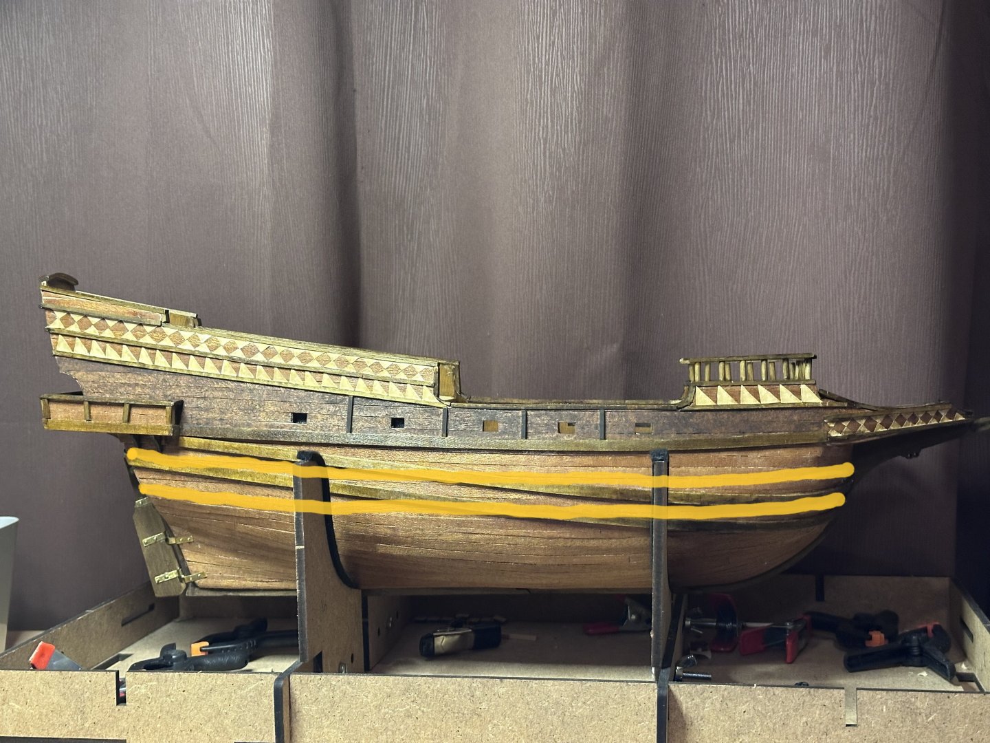
Good day,
Ah, I see...
In this case , balcony itself just additional, light construction, which could be placed in free position , lets say, iregadless of wales positions, but wales, they are important part of hull construction, .... and in this respect , there is no necesserity try to align them with balcony position , which is very minor consering wales and other ship hull elements...
As I could see on Your model, position of your 3rd wale is correct, and it well , harmony aligns with balcony position... that why your decision to place" imitation" of 1st and 2nd wales became eyes catcher if I could say that...and I started placed my comments...
logicaly it could be supposed that 1st and 2nd wales be placed just running proportionally to the 3rd wales...bellow balcony...?
-
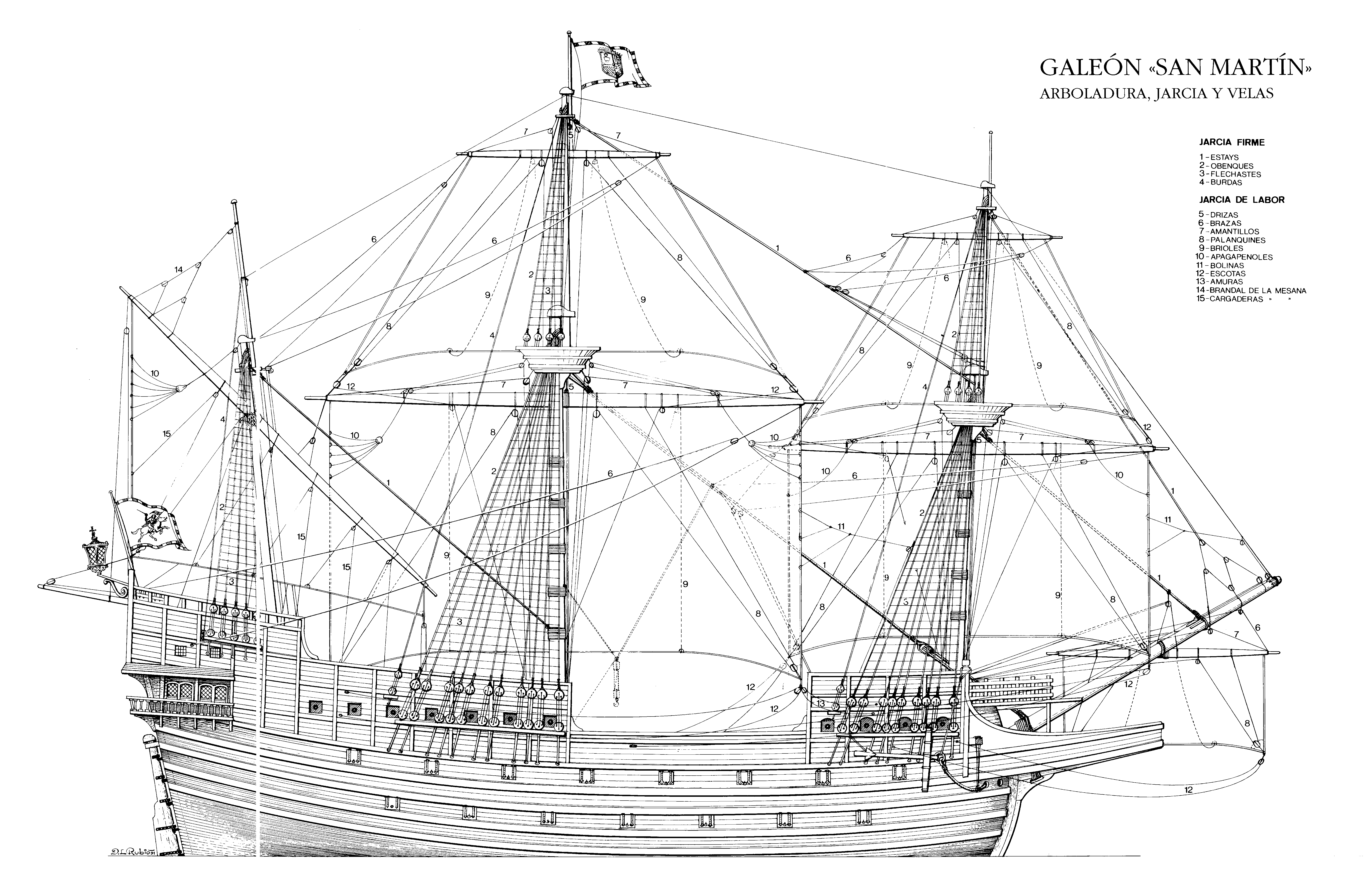
Beside mentioned above, I have some drawings of spanish galleon model which rigging diagrams You could use instead of Ocre rigging plans , at least they are much more corectly made!
СантЯго-де-Компостела-01.pdf СантЯго-де-Компостела-02.pdf СантЯго-де-Компостела-03.pdf СантЯго-де-Компостела-04.pdf СантЯго-де-Компостела-05.pdf
-
Good day,
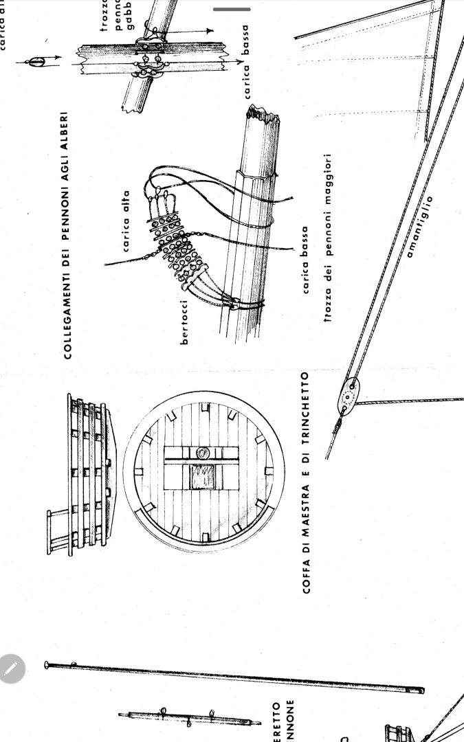
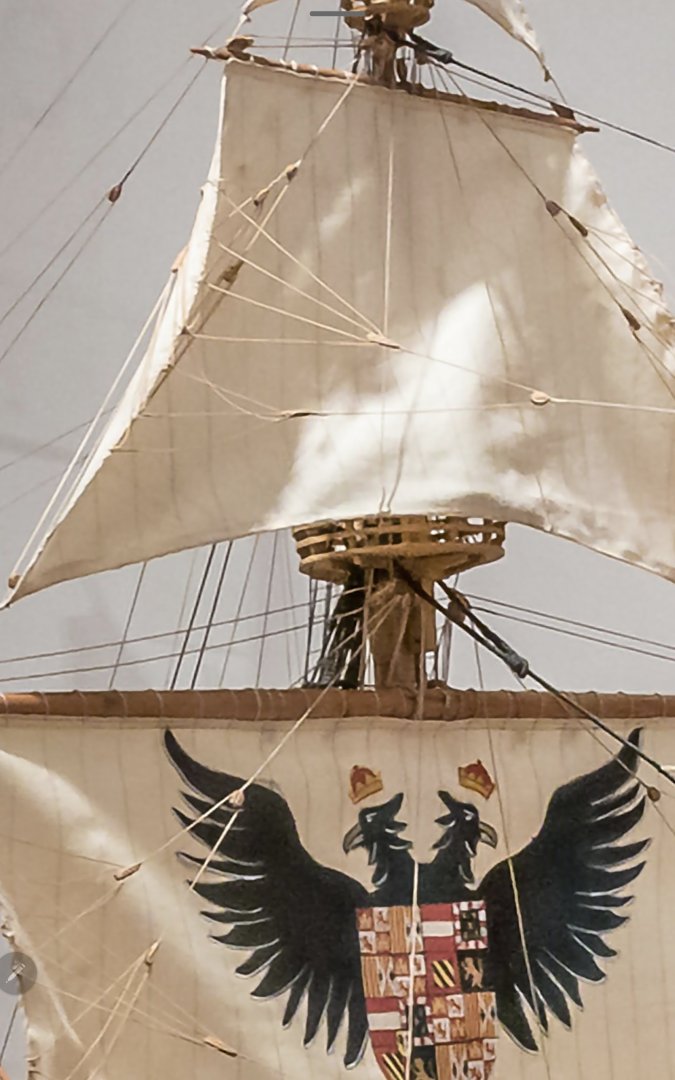
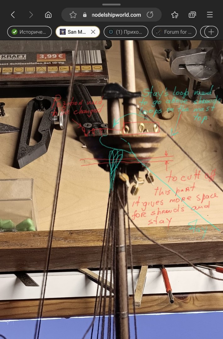
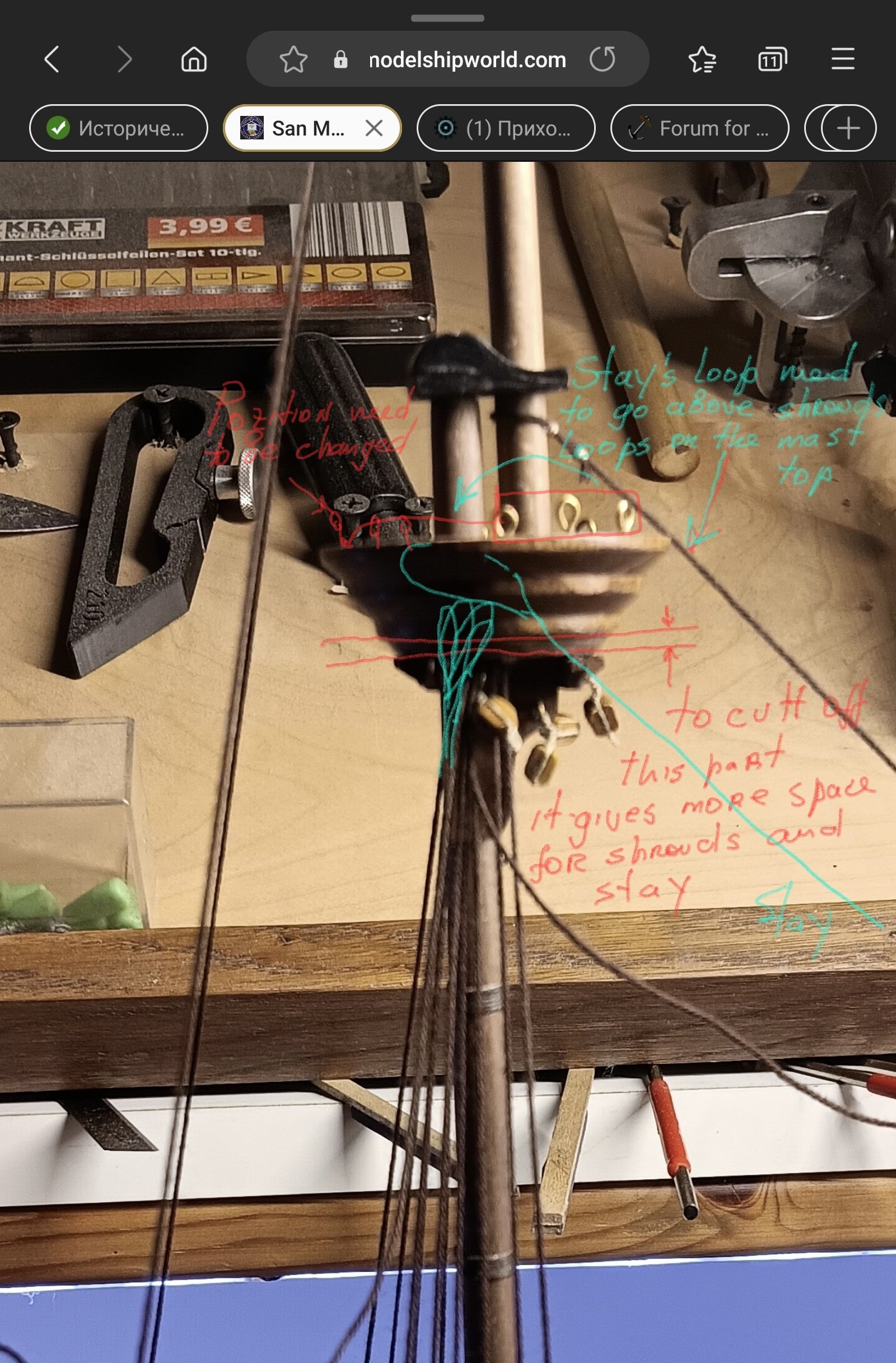
One of the solution , by my opinion, it could be to increase a little bit opening in the lower part of the top - this will give you some extra room for passing shrouds and respective stays , for increasing opening in the lower part of the top, you would be need to cut off one of its lower layer.... and rearrange a little top floor...
At least,when I m looking at the posted pictures, right now, the size of the top too small to be correct and there is too small opening in the lower part of the top platform...
There should be sufficient space to accomodate all shrouds loops and stay loop above them...
The secuence of rigging is quite important...
lower part of the top mast shouldnt be used for attaching stays,shrouds or any other rigging lines...
And I would like to recommend to take a break for a while with rigging and to spend a little time to read R.C.Anderson book about rigging matters... it is not necessary to read it complete, but a few pages only where he talks about certain issues which You faced in your rigging...
When You will follow rigging with understanding and sure what and how the process should goes on, current situation will not looks so dramatic as now.
As seems to me this Ocre kit still manageble, and good kit for start,You did very good work with the hull, but current spars and rigging questions are minor and could be easily be corrected by You because You already have good experience to work with wood for these correction...
I would advise , at these stage, to avoid using original Ocre rigging and sails plan anymore ,which only create for You very big mess and confusion but to use any other professionaly desighned rigging and spars plans which will suitable for spanish galleon rigging,
I would like to mention in this respect one of Ab Hoving's books about Dutch shipbuilding traditions where He gives step by step instructions how to fitt all rigging and sails with technically correct illustrations of typically europian galleon of the beggining of 17th century... rigging plans from this book could be almost directly using for your spanisg galleon model.
It is europian style rigging and similar period with your model.
But first, as I mentioned, there is a sence as seems to me, to take a break,
*to read that Anderson book , where He gives all necessary explanations in very simple manner,
*to look at that Ab Hoving rigging plans ,kipping in mind what You read in Anderson book and compare with Ab Howing plans
*to draw on your own rigging diagramm and than to continue to rigg your beatifull model...
All the best!
Kirill
-
Goos day,
She looks nice, sometimes I even can't believe it is the first your build !, but
, with wales position, definetely something went wrong, they should be more or less in parralel to each other with curtain sheer of couse , but not like You shown them, I'm sorry to say, but, right now, they are in wrong positions, it would be better to place them correctly for galleon model....
Very interesting, what was the reason when You decided to place them like this?
Wales in principal, they are the same planking as others planks, but only thicker, they used to reinforce ships hull construction, and because of this nature, they couldn't run accross adjustent planks, all runs in the same directions...
.thumb.jpg.e5a5f11bb2dbfee93f1a23d14f52d91a.jpg)
Aregimentforthesea.SourceCreatedorPublished1592.thumb.jpg.bbd3d18c9d4177cd0ae3ce2fecd71dc3.jpg)

- PeSt and GrandpaPhil
-
2
-
Good day,
Dear Pfalzer ,
Honesty I even don't know what to say...
from one side, what maker of this kit do with rigging of his own kit, from historic or technical point of vew, it is just ...lets say , looks very very strange and funny to see how they brake all imagiable limits and rules of shipbuilduing tradition:))) ...
from other side , You told that You are very experienced in technical fields ,at least much more experinced above normal housekipping's life of ordinary people, and from this point of vew, it could be twise relaxing to make corrected rigging(rigging which will be working in reality as well as on your model )of your own model instead of to follow and reproduce these fully wrong ideas of maker's instructions , which looks like meaningless set of rigging lines :)))
... or ,once again, it could be same relaxing way just to follow blindless kit's instruction ....
First , I thoght that it were your own idea how to make galleon riggings, looking at those pictures which You posted , but now I see, that You just carefully follow maker rigging diagrams, which are unfortunatelly fully wrong...hm...
From third side, we could just follow kit's instruction 100% ... why not? ... but for me personaly , it would be not so fine to have these fillings in the background, that all my rigging I m making so carefully , I'm making carefully wrong ! and I know , that I'm making it wrong because kit maker did it so wrong by unknown reasons...
-
Good day,
Dear Pfalzer,
I have some principal remarks regarding your rigging sequence , correct sequence should be like that:
*first mast tackles long stropes should be fitted,
*than shrouds,
*than stays - their loops applied above shrouds loops which in their turns should be applied around mast top, lower part of the top mast should be left free, it is wrong to connect upper part of the main or fore stay to the lower part of the respective top masts
*and finaly back stays if they are in use
These nuances about correct rigging sequence could be easily found practically in every ship modelling book.
Wood works of your model are very cool, and from my point of vew , it would be nice ti fitt all your rigging correctly not ruining nice model by wrongly installed rigging... by the way, lower part of the stays should not be connected directly to the spars ( masts or bowsprit), for that tackles need to be used.
ps
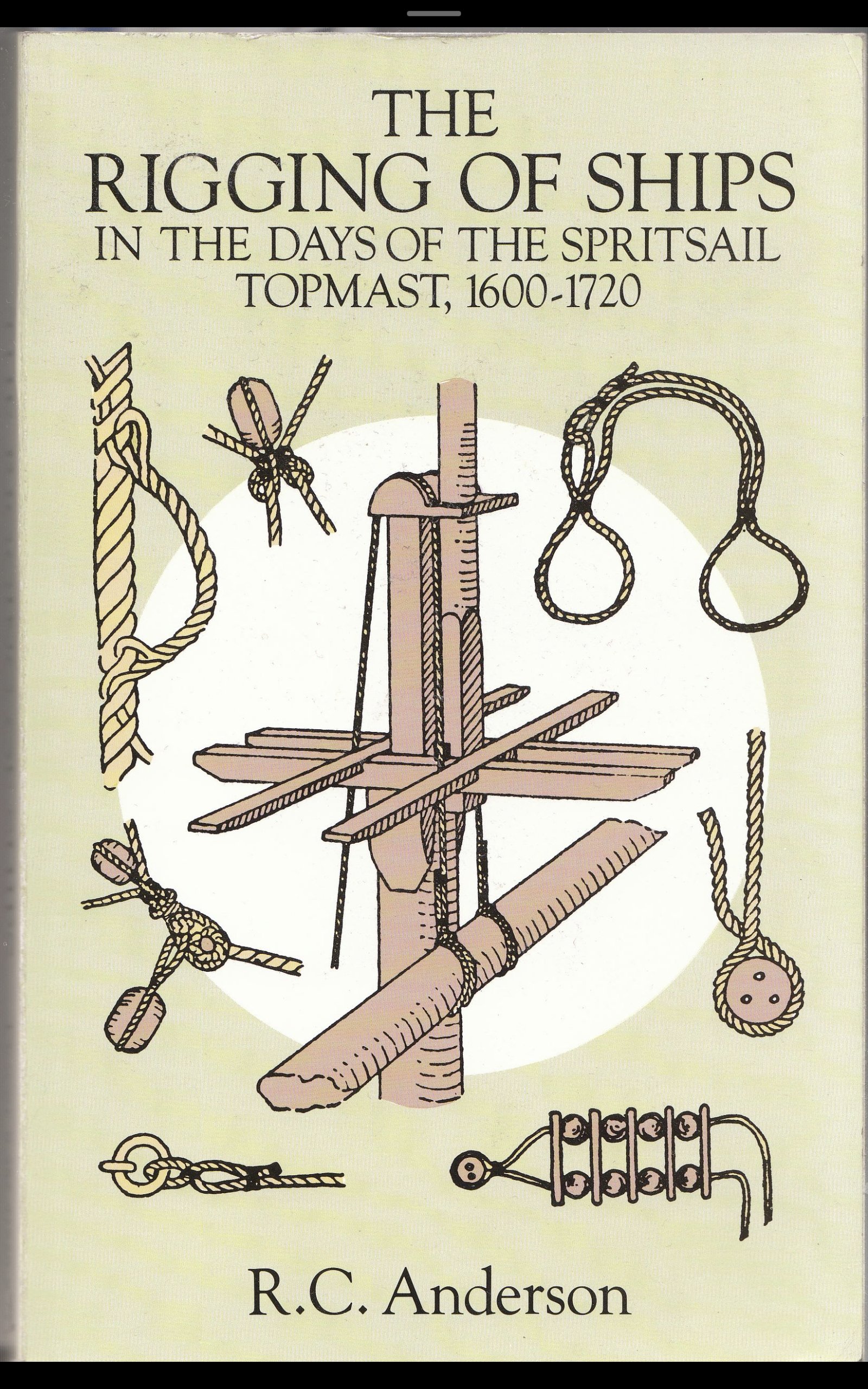
There is very nice book abourd rigging which could be fully implemented in case of galleon rigging - R.C . Anderson " The rigging of ships. In the days of the Spritsail topmast 1600-1720"
-
Good day,
Dear Loracs,
I'm sorry mentioned ratlines -it is no the case here , they are quite correct in size and colors on your model! Sorry for mentioned ratlines...
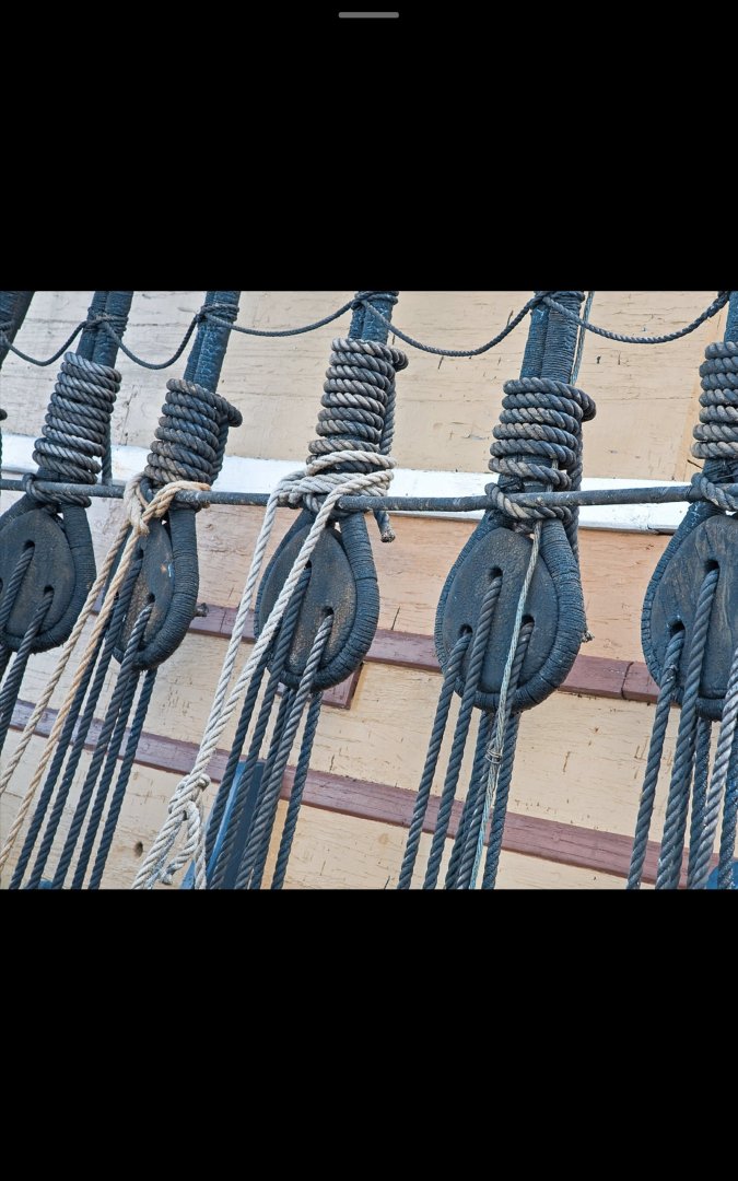
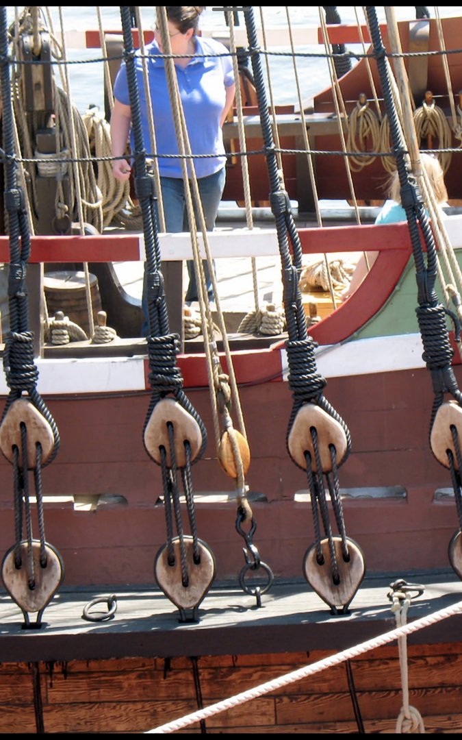
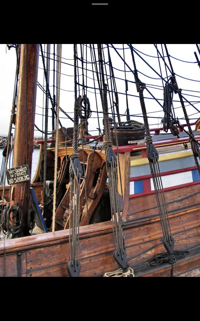
As for the laniards of the shrouds, yes, there is steady tendency they used to be tared, and normaly should be the same color as shrouds... that what we could see on replicas and what is more interesting for us as modellers, autentic admiralty museum models , they all have tared ratlines and shroud deadeyes laniards ...practically they easily could be stained to the dark colors with suitaboe stains or deluted acrylic paints and fine brush justcright at places where they are fitted...
All the Best!
Kirill
-
Good day,
She looks great! Very nice work!
Some remarks - laniard color , consider they used to be good tared , and color should be dark, same as shrouds colors, and while You are busy with ratlines, I hope You to take care about their thicknest, often we could see that people made them too thick/ oversised and thus ruining overal impression of the fitted shrouds ...and color of the ratlines - need to be the same as shrouds as well...
All The Best!
Kirill
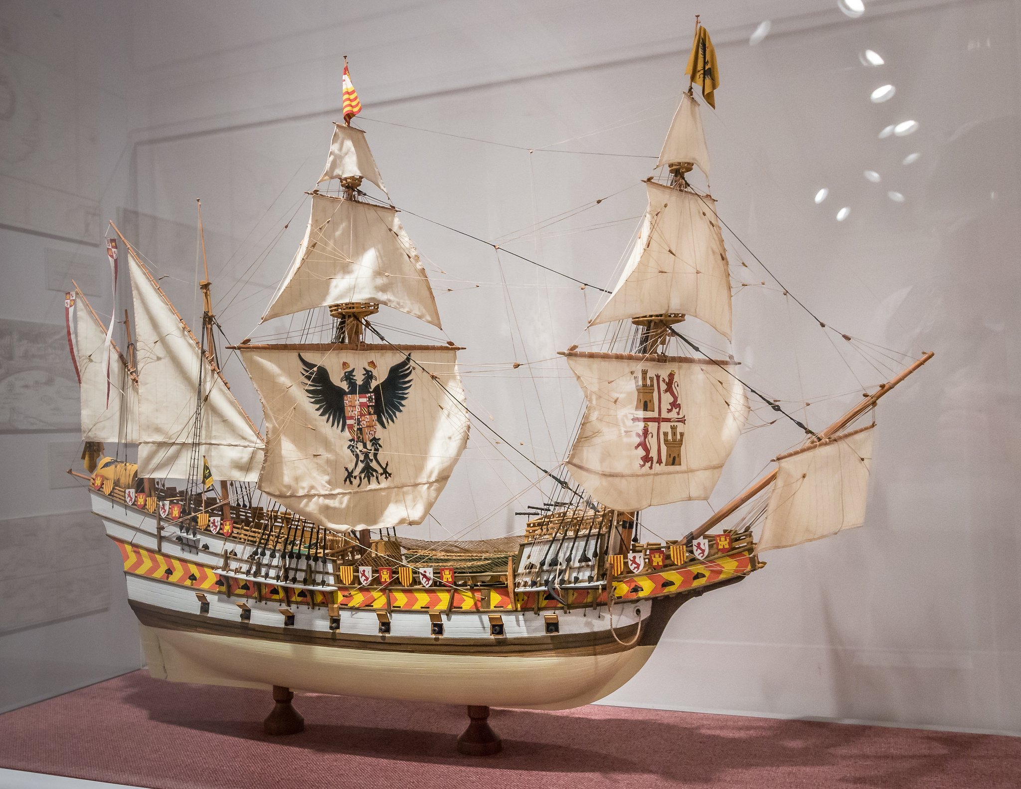
A few pictures of modern replicas - where we could see how triangle deadeyes fitted correctly and laniards tared as well - Mayflower, Duyfken, Half Moen
- firdajan and GrandpaPhil
-
2
-
Good day,
Dear all,
A small continuation - placed shields, chess-tree , cat -head , clamp for main course sheet, tried on gun port covers at place, anchor beam, added 4th barhout...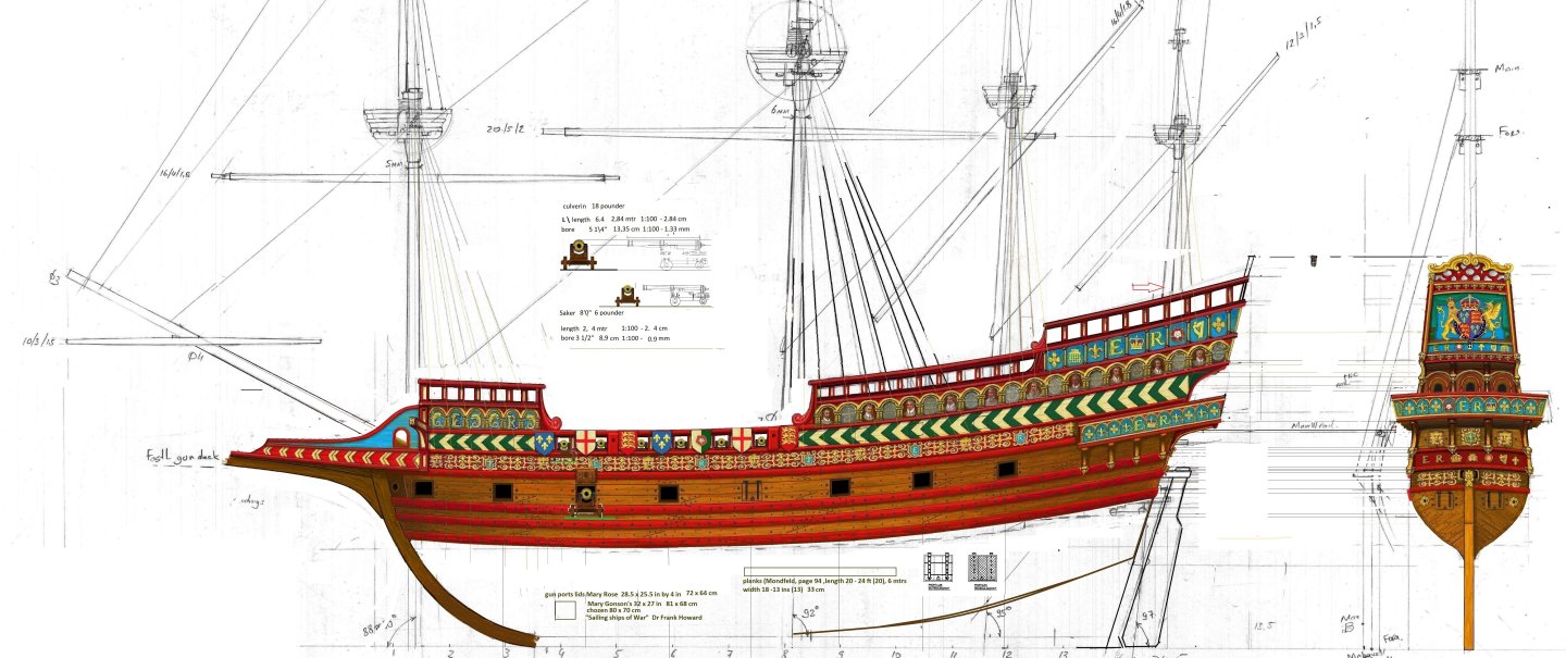
- firdajan, Baker and Knocklouder
-
3
-
Good day,
Dear all, here is a few steps forward with this project ... continue with bulkheads decor
ps
Have problem with downloading picture, here ia the link for the same picture
https://karopka.ru/bitrix/components/bitrix/forum.interface/show_file.php?fid=2784979
-
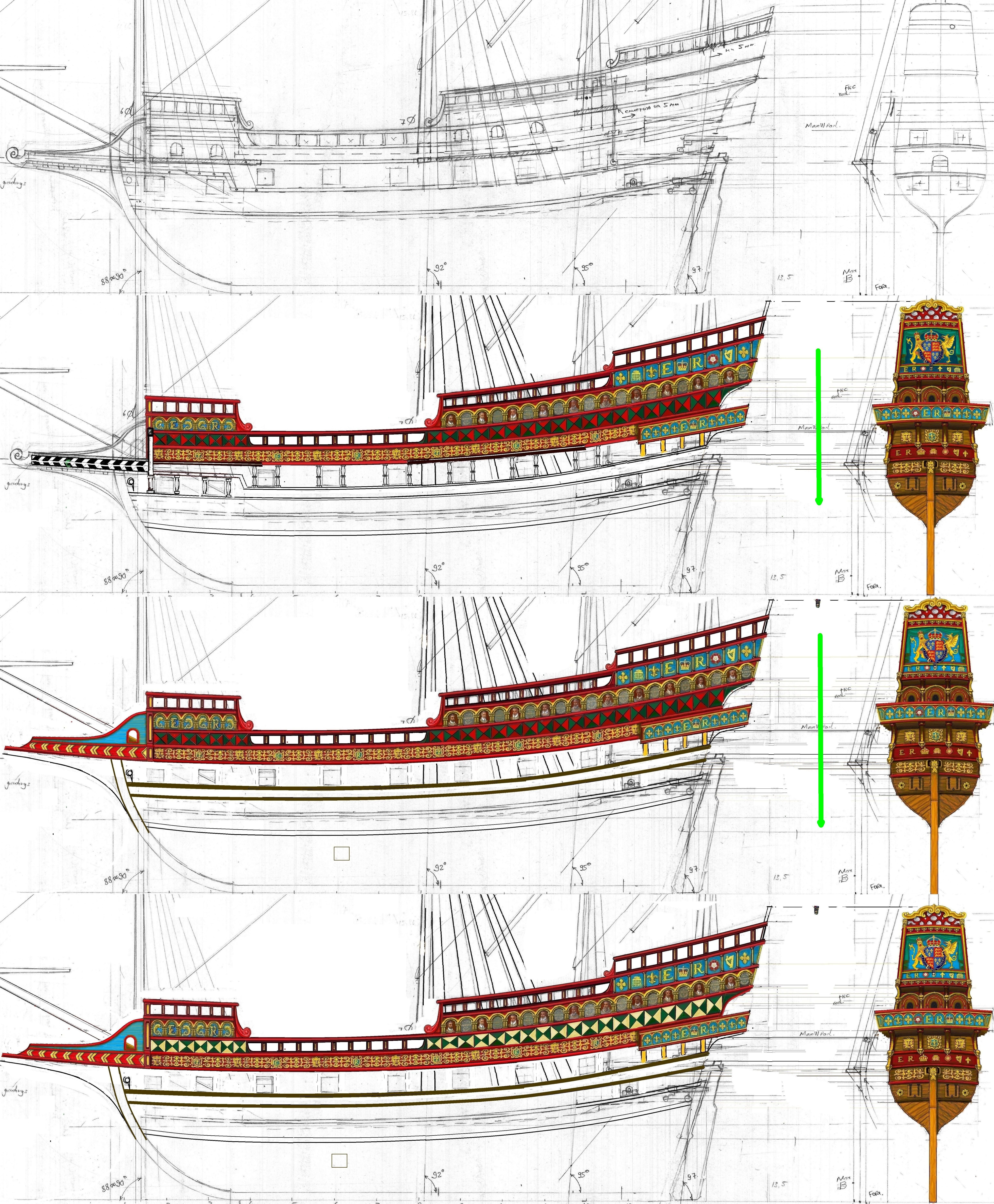
Greetings a respected community!
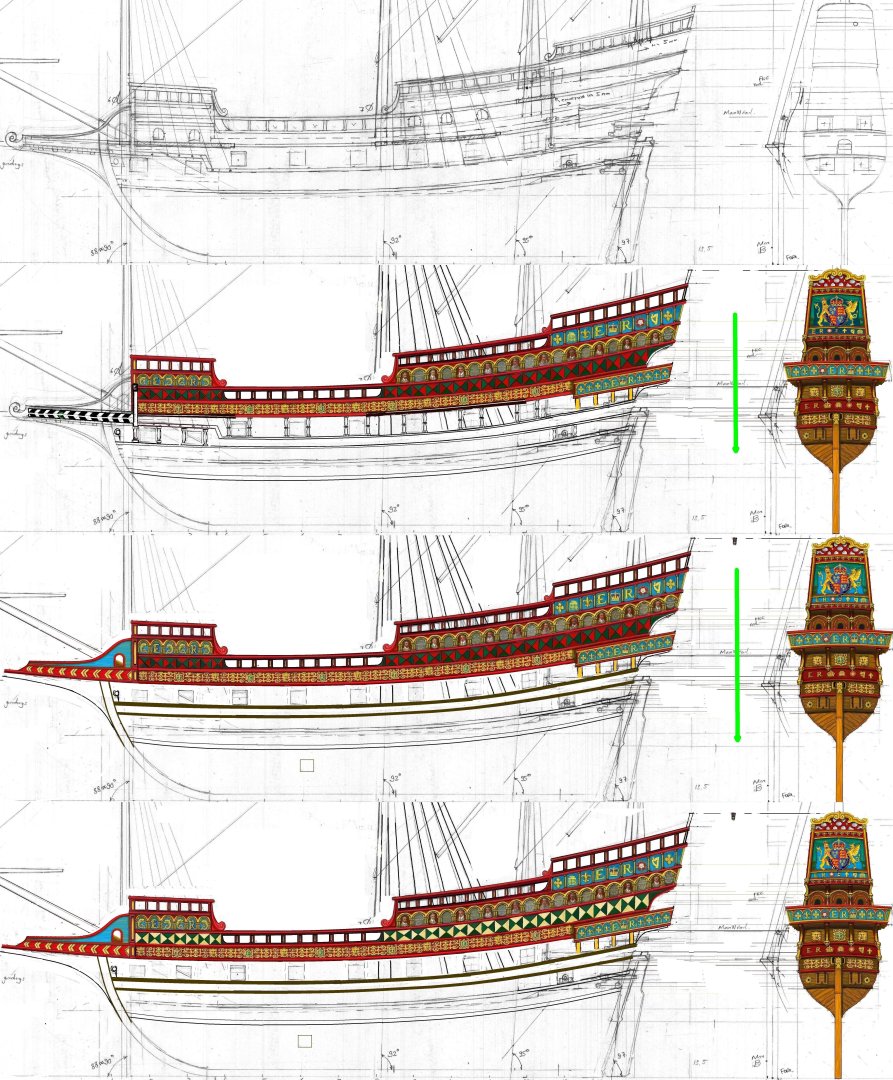
Recently I've made some small changes in my project , in the continuation of the story, so to speak -
* slightly increased forecastle height *raised the beackhead deck - in principle, by this , I've just returned to the original composition of the kit ...
* and refused to reproduce the step in the forward part of the main gun deck ... something, well, it "did not go to me" despite my lovely model of Elizabeth Jonas galleon ,
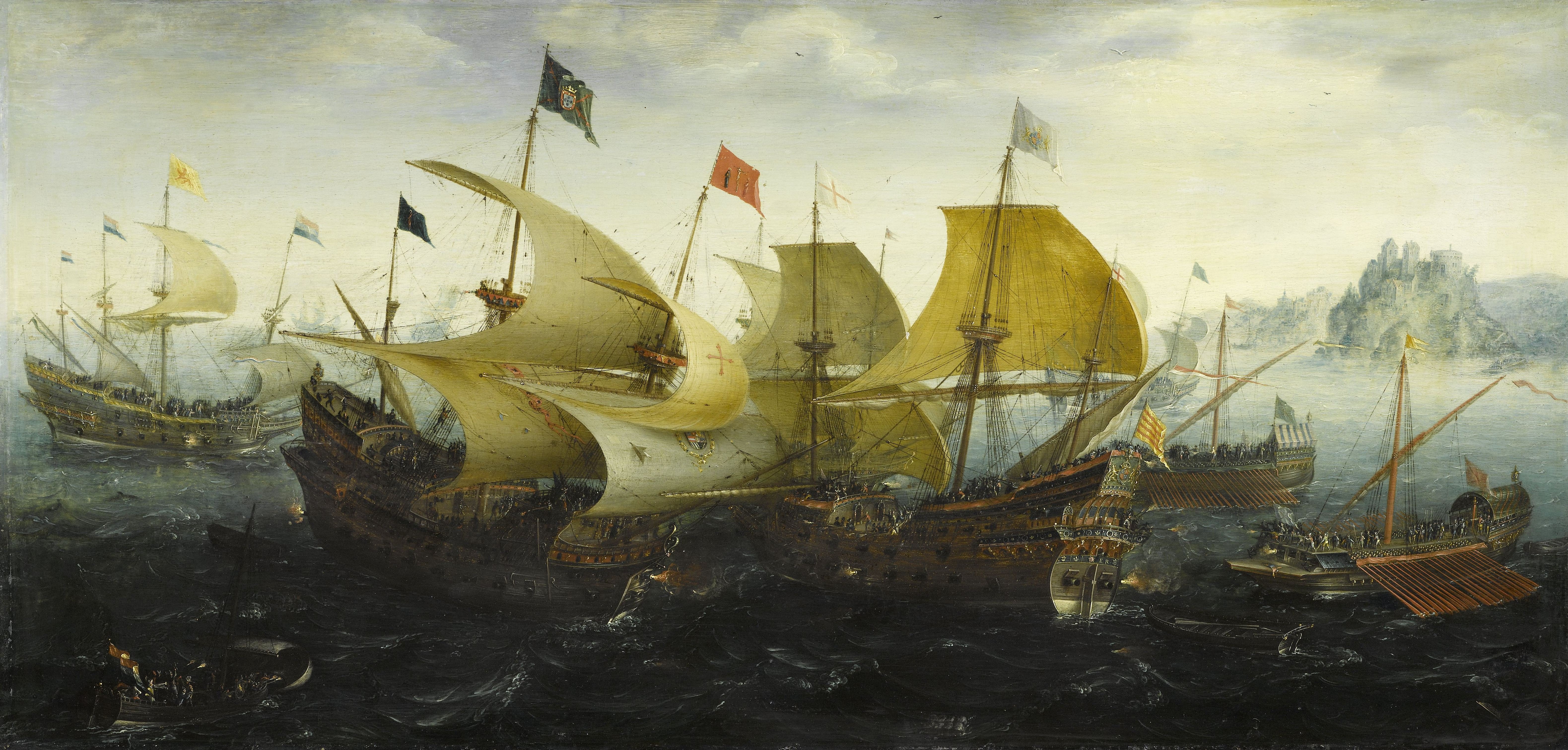
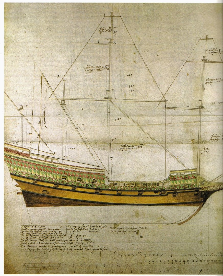
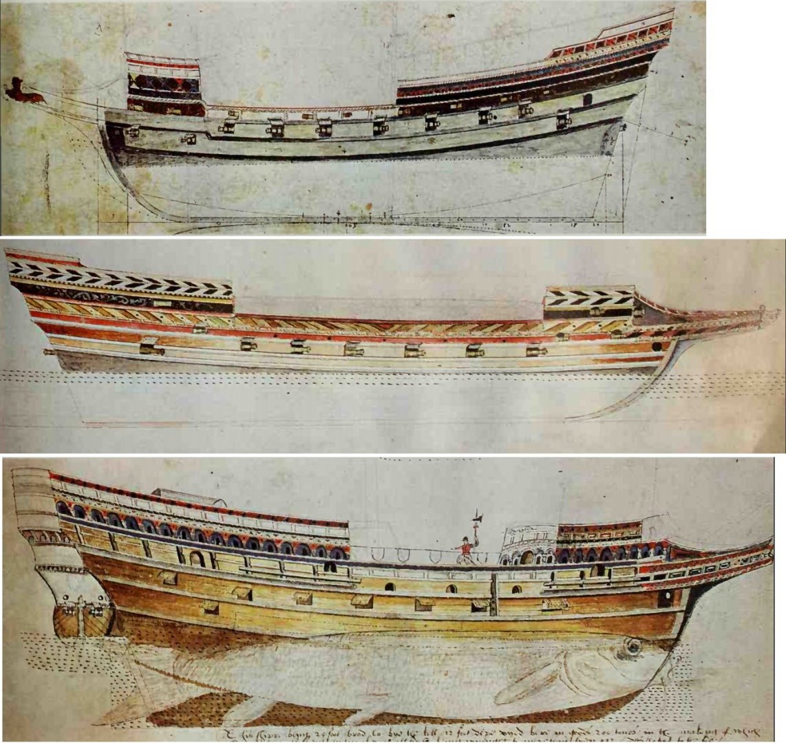
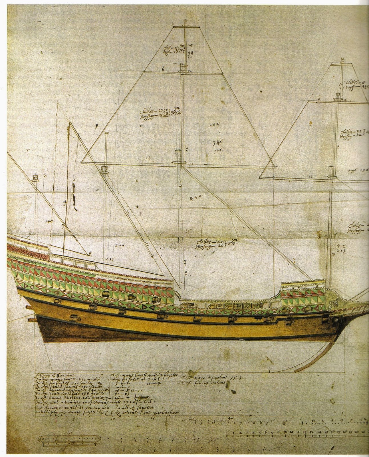
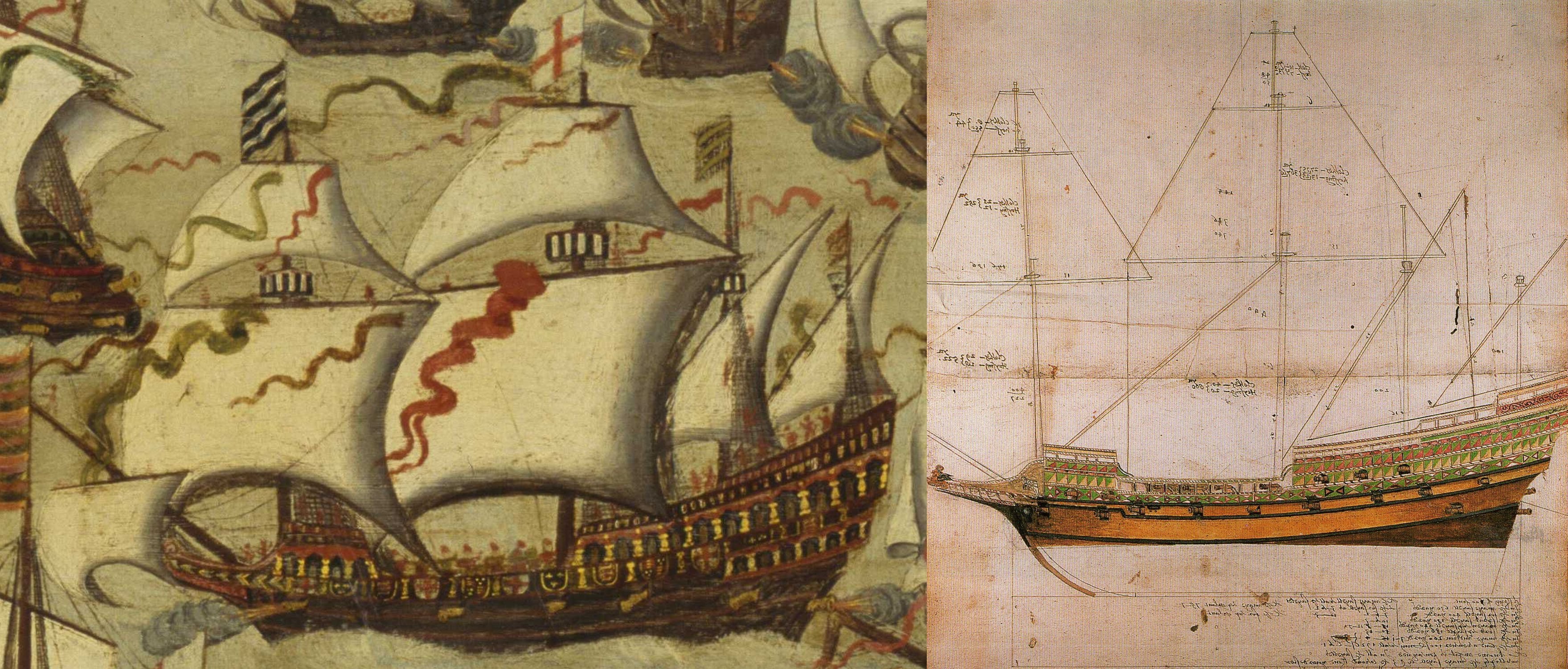
either on the famous Baker's galleon drawing , and then, judging by the drawings and paintings of that period, the step in the nose is not an indispensable attribute at all, as an example
- two pictures, with a step (Galeon Baker) and without ...
But in the stern - as a rule, this deck break was present at many pictures of the galleons and this break of the deck , even well traced up to the middle of the 17th century .... therefore I left the original option ...
*In the on -board decor I added Tudor's colors - white and green ...
So far...
Wish all of you all the best!

-
-
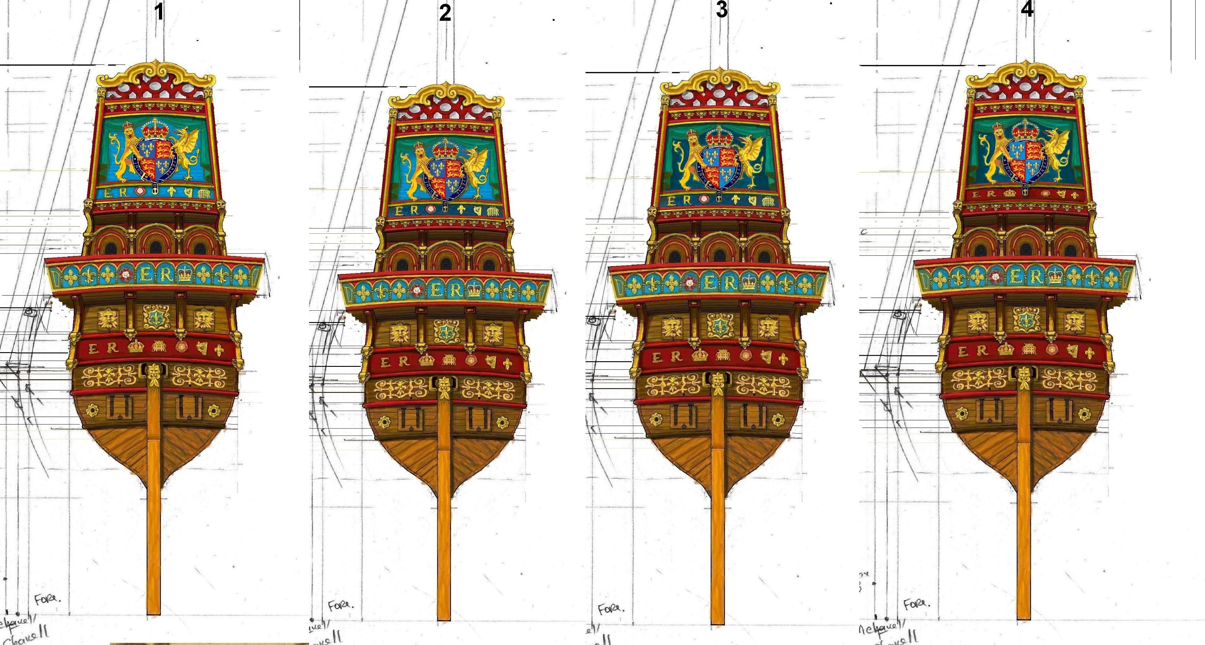
Good day !
Dear community,
Please to value / comment a few versions of heraldic shield decoration....I prefer variant N4


.jpg.b21cd7a030f32be53cae412f49c6678d.jpg)
Aregimentforthesea.SourceCreatedorPublished1592.jpg.36985fcd38ac9ee9030d57c979f25a64.jpg)


Roter Löwe 1597 by Ondras71
in - Build logs for subjects built 1501 - 1750
Posted
Good day Ondras!
Very interesting detailes added! And in common - it is masterpiece work!!!
Greetings with upcoming NY! All the best in new 2026!
ps
( in case You don't have them yet) 5 volumes - books 16th century spanish whaler(typical galleon 16th) in details , it could interesting ... ... https://publications.gc.ca/site/eng/9.946496/publication.html