robipod
-
Posts
202 -
Joined
-
Last visited
Content Type
Profiles
Forums
Gallery
Events
Everything posted by robipod
-
 Lawrence: will see what I can find on this side of the pond. Thanks for the tip.
 -
Daniel Just going over these comments and realized I did not thank you for the picture of the rudder and your comments. Very much appreciated. I can see that there is not much overlap as you say. I was somewhat confused by some of the books and info I was reading about overlapping the tiles but in the end I just figured as you mention that the scale that we are using it would not reflect and besides, I also figured it would look nasty if I really did try to overlap the tiles. I just stuck to the 50% stagger on each strake. Thank you for joining in. As said, really appreciate the input.
-
Lawrence... just figured out how to do this... should have done for Daniel too. However, I do have a question. How do you get one of those little tubes applied to the CA glue bottle? Do you glue it on? When you put the tube on, how do you seal the glue bottle for the next time use? It sounds like an idea I should try.
-
Lookin' awesome Pompey. You've been busy! I put mine on hold for a while. Got really busy. Have been back at it now though. You have to post a picture of her when you have the interior lights on. I only wish I could have been as neat and tidy as your interior. Decks look splendid! Figure I'm on the copper plates for the summer at the rate I'm going. Am very slow at them but, as I said to myself during planking... "one plank at a time"... well now I go "five plates at a time". All the best to you Nick! Lookin forward to the next posts.
-
Just want say thank you to all. This is really interesting creating the model and having these discussions about the "real one". Thanks for taking the time to share your thoughts! Oh, and for Fortress: спасибі всім вам. це дійсно цікаво створення моделі і мають ці дискусії про реальну.спасибі, що знайшли час, щоб поділитися своїми думками
-
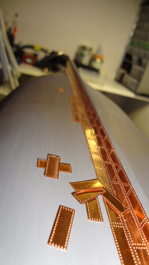
As noted earlier, I started the tiles. Read about it too way much, but I remember one comment where someone suggested 'just start, take it slow, and it will work out'. Well, that's exactly what seems to have happen. I found today that I would wonder into the shipyard and put on three or four tiles, stop, go do something else then come back. Plugged away off and on today as it has been one of those really wet spring days. Rain all day basically. I wonder if it snowed in the mountains? Back to tiles. Yes, I went really slow, used the magnifying glass all the time, kept the laytex gloves on, and used the blade and tweezers. The results are not bad. There has been some discussion about painting the hull with a primer, versus leaving it the unfinished walnut. I find it very useful with the hull the light grey. I get a great contrast between the tile and the hull. It is very clean to work on. I did sand the primer coat and was checking for any really weird spots. Will see if I can do this side in a week. (I think this is an ambitious goal - lol)

-
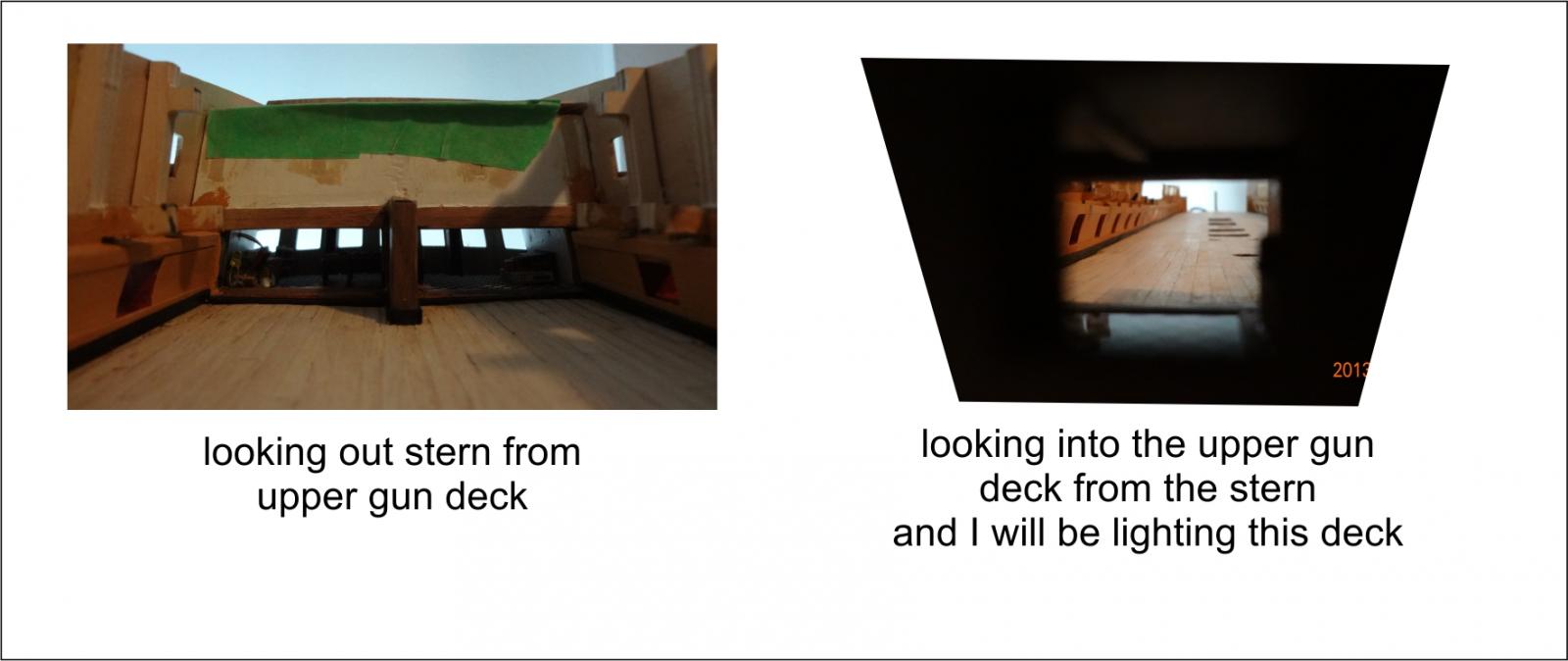
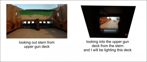
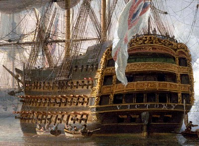
Konstantin The images by Turner are fascinating and remind me that 'in battle' the decks would be cleared to be ready for firing the cannons. All the screen bulkheads would be lifted and secured to the ceiling of the upper deck. When I look at my Victory, I have created somewhat of a battle ready state particularly for the upper gun deck. I have the deck completely open so it can be viewed from the stern to the bow. I have pretty much decided from these images you showed to not mount piece 389 to the upper gun deck (the upper deck screen bulkhead). I am constantly impressed by your knowledge of the ship. Thank you for making me think of this.
-
Terrific to see you post this Pompey. Have been looking forward to it!
-
Started the copper plates. Figured I would start at the keel and go up. Box a box of latex gloves to handle the tiles. Works really well. And I opened all the tile packages and put them in one open container so they will oxidize at the same rate. The way the model is right now, placing tiles up will be actually be going down. Will make five rows from the waterline down to correspond to the upper belt. Am thinking I will change the model up and take off the stand when I do the upper belts. Will see. Not so sure about this overlapping on the next row. If I don't speed up, it will be Christmas before I get all the tiles done. I edited and sped up the video on this tile... let's see the actual was [i don't want to say] just way too long... LOL.. oh well, timing will improve I hope but if it doesn't, it doesn't. If anyone has suggestions they are welcome.
-
Right on Kevin! thanks....
-
Joe This is a painting in the National Maritime Museum in Greenwich, England. One used to be able to order photographs from them of various paintings they had in their collection. Take a look at the website. I am sure you can still order. http://collections.rmg.co.uk/
-
Gil Did you ever see this one of Victory. Pocock Painting - they could have a decent bbq on the balcony...
- 295 replies
-
- 1
-

-
- victory
- caldercraft
- (and 1 more)
-
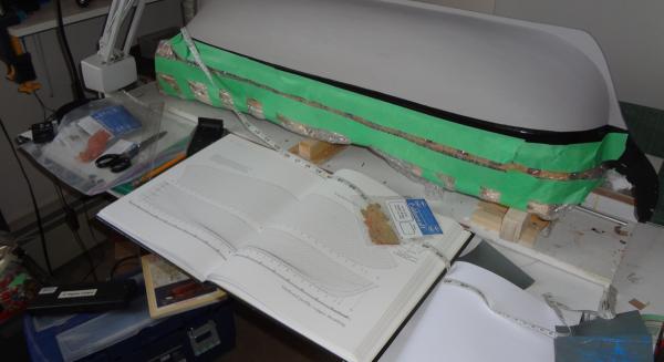
Still struggling with the concept of the copper tiles. Did some math last night. The Jotika plates are 17mm long by 7mm wide. Measured the distance at mid-ship of the plating surface. About 172mm. If I do not overlay the tiles, that would be approx. 24 rows. If I overlay the tiles by 1/3 (2.3mm) it would represent approx. 37 rows. If I overlay the tiles by 50% (suggested in the Jotika manual) it would represent about 49 rows. (these are close figures - not exact - but close enough) Now here are the figures that throw me. After measuring the length of the hull and taking a worst case scenario with the number of tiles per row I ended up with approx 850mm laying the measuring tape on the waterline (one side). That would be about 50 plates. If one says 50 is the max but there will be less at the keel, approx 780mm - that would be about 46 plates. Here is where I get concerned - say on average 47 plates per row that translates to 1739 plates per side. For both sides - 3478... but I have 2600 tiles plus an extra 200 that I ordered at the same time as the kit. Looking at McGowan's HMS Victory, Her Construction, Career and Restoration on page 140-141 is the expansion plan of copper sheathing. There are 37 rows: 12 rows on the top from the waterline (can't remember proper term) and an additional 25 rows from keel up to the 12 from the waterline. Here is where I get confused. (Wish it was just a mountain of snow... could figure it out... LOL...) Virtually all the photos I have seen the tiles are 1. not overlapped and 2. as questioned before do not seem to have the 12 row apron from the waterline. Question: What does one do? Overlap - and if so, do I have enough tiles? Any comments would be appreciated.
-
Gil Thanks for the comments. Am struggling with the copper plate layout. Will go into detail in the next post. I read you are off and away to sail the west coast up to Alaska. Have a safe and most awesome journey. I took the BC ferry from Prince Rupert to Port Hardy one summer. It was fascinating just being on the inside passage. Just stay clear of those ferries... lol... Victory looks much different with the open stern. Guess the Admiral and Captain didn't go on their balconies very much... no barbecue's on the balcony for naval officers... We are all taking license with the ship just like her builders over these two hundred plus years... heck... who can dispute what the actual ship was in 1805. they should have had digital cameras... hey, maybe The Doc and Marty McFly should use the DeLorean and go back to the battle.... guess they'd have to hover.... that would solve it!
-
Konstantin Thanks for updating about the bowsprit. I see what you are describing. Hope you got those three items that I sent to you! Thanks for being along here.
-
Chris Thank you for the comment. I know exactly what you are suggesting. Must admit when I first saw your idea I was thinking, .." wonder how the plastic would look on the model?" And it came to mind that maybe I wouldn't use it because it was 'not wood'. Well, then did I laugh at myself. Here is a person who has put fake photo interiors, fake plastic lights etc etc. into the model already... Yes, I will get some because it will be very useful. Have a friend who has a car detailing shop so can get various thicknesses. Great idea. Am very pleased that you would even read my post here as I consider you one of the best in the world. Maybe I'll have to finish this one and then go purchase the Amati Victory, when it arrives. Maybe Vanguard would be fun to build. This one will have been practice...
-
"The Victory's copper is laid in two belts, the upper belt having twelve strakes and over lapping the lower belt" is from Longridge in his The Anatomy of Nelson's Ships. Most models I see here do not appear to have the twelve strakes at the top. most are one or two. If you have the book, the pull out drawing on page 36 shows this pattern. Am tempted to measure the distance from the waterline to keel and divide by the width of the Jotika supplied tiles to see if I should be starting the top twelve rows and work down while working from the keel at the stern up. It would appear that the twelve rows from the waterline down should be completed before the keel up is done. (does this make any sense?) Have you overlapped the tiles? In his book, Longridge states "On naval ships the upper edge of a lower strake overlapped the lower edge of the strake above it." I am not sure that I've seen the tiles overlapped. Is it an optical illusion or has everyone overlapped the tiles in the manner suggested by Longridge?
-
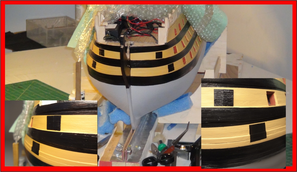
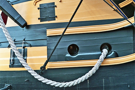
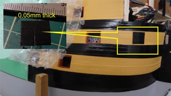
Finished the faikies... Now I must admit that for the lower gun deck I couldn't figure out how to use the 0.05mm veneer. So looked more and more at the pictures of the real Victory and found this: Took my gun port pattern and drew on the hull. Took a flat xacto blade and hammer - I can't believe I used the hammer - and followed the outline with the blade. Didn't turn out too bad. Am pleased though that I did the middle gun deck gun port with the 0.05mm veneer.
-
Today decided I better finish the closed gun ports near the bow. I wonder why Jotika doesn't cut them out of the plywood? Maybe the curve at the bow puts too much stress on the wood and it splits with the ports cut out. Oh well. In the instructions it says ".... They are then scored with a sharp craft knife, simply to represent the gunports in a closed position..." There is no way I can score the hull and make it look reasonably rectangular etc. and be somewhat decent looking. I've been thinking about them for a bit and decided to do this. I have a local supply of .05mm walnut and maple veneer. I took the outline of a gunport and then drew it on the .05mm veneer. Cut the veneer out... oh, before I cut the veneer used some CA glue on the back to bond it a bit. Measured the mid-point... cut them out and this is the result. I don't think there will be much problem with the hinges. (I hope not anyway). That's how I'm solving the closed gun ports and making it "look a bit cleaner". Am doing the same for the lower gun deck closed port. The vertical split does not show too well in the photo but when I look at it, it's there.
-
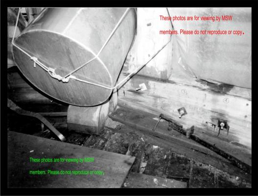
Konstantin - your knowledge of the real ship is so impressive. Thanks for this description. The upper right of the photo I took is a plastic tarp.
-
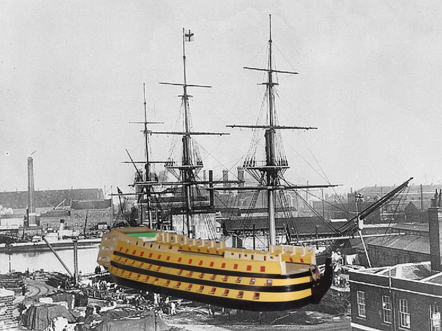
Just realized I haven't posted my final of the Victory reconstruction. Here it is. At the bow in '83 or so. Left this in a higher resolution and pixels so you can see the details of the wood and construction at this point of her. Any thoughts as to the significance of the 1,2,3,4? Am thinking Konstantin will know. I have no idea. Enjoy
-
looking good Erik. Made a comment about a second set of lights in my build. I used the middle deck as practice too. really like the concept of lighting you are creating. Oh the joy of planking coming up! Are you taking the wiring out the keel?
-
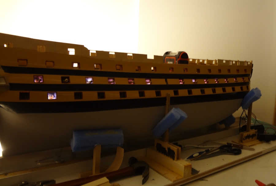
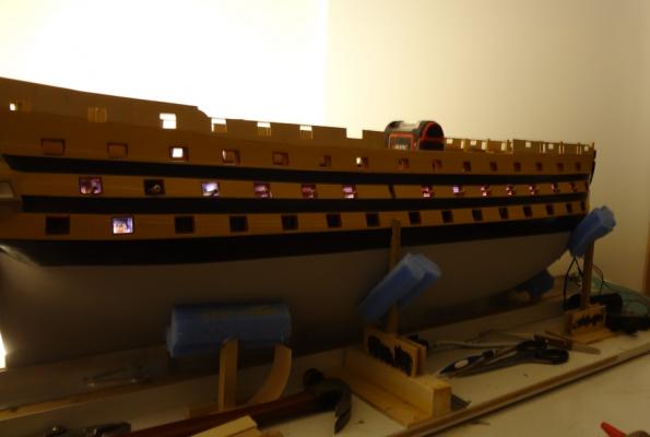
thanks Josh... am going to have to do catch up on everyone's build this week. Will start tonight Erik thinking of two purposes for the extra set of LEDs . 1. As a back up when the first set goes/ or might go but am also thinking that if you put the extra set in now and find the one set of LEDs is not enough to give you the right kind of light... and 2. the second set would give you the option of having both sets on at the same time. I should send John a note too about making a redundant set of lights too. That is something that i would definitely do now. Mind you I don't have the electrical skills to achieve it. I am going to add an extra light or two on the ceiling of the upper gun deck just for the sake of having the spare. Erik I've read the comment on lighting for these ships that less is better for the interior because the candle/oil lamps they used would not throw much light if any. I totally understand the comment. However, what I've seen so far is that I don't sit in a completely dark room.... That is reserved for the bedroom... LOL By having very little light shining through the gun ports they don't even look like there are any lights there. I was able to brighten the middle gun deck lights by re positioning them a bit to show more light. When my Victory sits in the room I can't see the lower deck gun ports LEDs flickering at all until I shut off all the lights. It will of course be personal preference but as said I've already brightened mine so that when it sits in the main area of the place, it will at least show the lighting with a couple lights off instead of all the lights off in the place. I wonder if I could get an image of what I'm saying here.. not even going to try. Was flipping through some images and I do have an example. There is a light on in the room directly behind the model. You can see the middle gun deck gun port interior from the brightened LEDs. Do I babble on or what?
-
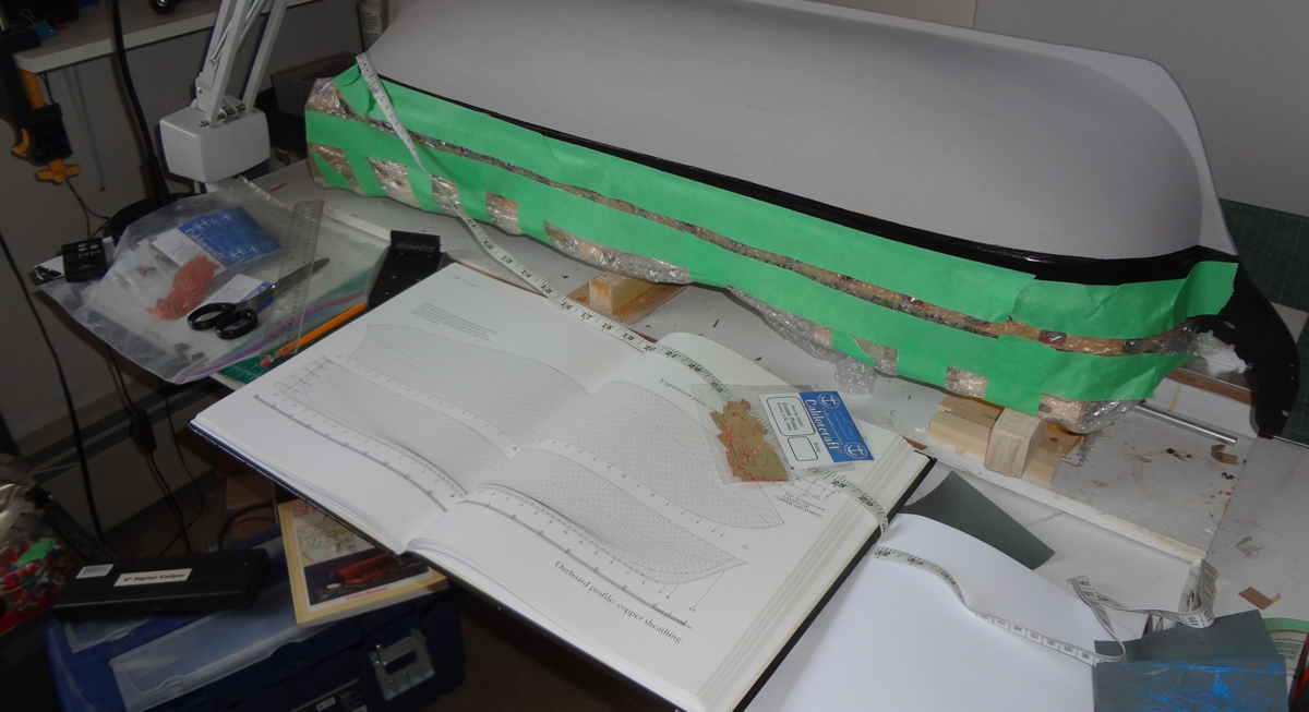
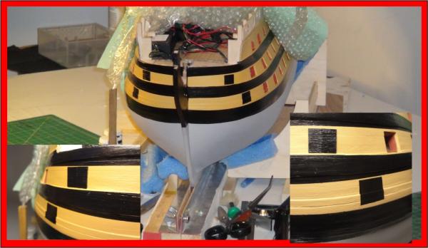
Erik. I looked at your build. Yes, I see where you are headed. If not too late would suggest you double the lights... have each on a different circuit so you can have a backup. At least I would do something like that now. Konstantin - thank you. Yes, you are right. The decks of the two ships may very well be have been different wood. Am thinking it comes down to what Erik suggests that it is personal preference. Progress has been slow, what has it been two weeks. I finally finished drilling the holes for the dummy cannons. All done. Messed up one on the starboard side but it will glue into place alright. The cannons also cut the light from the LED in the gun ports. They look alright. Will put them back in the tray and go to copper tiles. Will be reading about how to blacken the cannons later. Here is my Victory with dummy cannons drilled. Won't see this for a while. Will cover the sides now with plastic and tape. It's a long weekend here in Canada: -- Victoria day weekend. (Yep, named after Queen Victoria who was the first monarch of the Canadian confederation (1867) - For those who are not aware Canada has a constitutional monarchy and our current Queen is Queen Elizabeth the Second). Last weekend of riding for this season. Will be out in the mountains. Hope you enjoy the humour in the photo.

- 295 replies
-
- 1
-
-
- victory
- caldercraft
- (and 1 more)
-
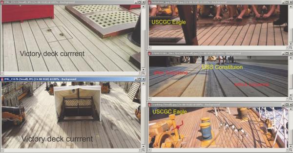
Fellow Victory builders I have a question. This one related to the foc'sle, quarter decks. On the picture below I've put a grouping of images on the difference between decks before and after the crew holystones them. You can see the sailors on the USCGC Eagle using the holystone on the deck. It is my understanding that back in 1805 Victory/ other British warships used holystone on the decks. Do you see the difference on the USS Constitution decks before and after holystone? Here is the question. Should the quarter deck(s)/foc'sle look bright and similar to those on the Constitution and Eagle or would you leave them the uncleaned look of the grey. I know some have "greyed" their decks. But is it more accurate to have them this other lighter colour. Would the 'worn' deck look similar to the left side of the Constitution image? Was anyone around in 1805? LOL... I 'greyed' my middle gun deck but left the upper gun deck a brighter 'buffed'. Would appreciate your comments. (Am thinking way ahead here. For that matter not even close to starting but it's been on my mind this week. We finally got spring in Calgary today! 27 ©..... we had snow last week... LOL (still lots of snow in the mountains!)