HOLIDAY DONATION DRIVE - SUPPORT MSW - DO YOUR PART TO KEEP THIS GREAT FORUM GOING! (Only 36 donations so far out of 49,000 members - C'mon guys!)
×


JSGerson
-
Posts
2,618 -
Joined
-
Last visited
Content Type
Profiles
Forums
Gallery
Events
Everything posted by JSGerson
-
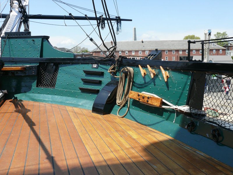
 Wow, I didn't know I was the "go to guy" on research! The only pointed planks I see are where the deck planks meet the waterway at the bow. These shown exactly the way look on the real ship. However, the hull planks, do NOT come to a point. Various methods are used to avoid that scenario, like using stealers and/or tapering. This is the way the ship is today. How it looked in the 1800s, I would not know. The earliest US Navy spar deck plan I have is from 1928, and there practically no difference from the kit's plans.
 -
Beautiful planking job Pete!
-
Just about every surface of my model is covered with something, be it copper, paint, or stain. I have not used polyurethane (Wipe-On Poly)...yet. When I use paint, it's on bare wood so it soaks into the surface. I've used basswood, boxwood, and pear wood so far. The only wood I could have used the poly was the pear wood which was already the correct color I wanted. I didn't use it on the couple of wooden columns and bitts I made with it so far which are barely visible, but I may go back and touch them up with it. And yes I too get cases of "analysis paralysis." Jon
-
I am starting the main grating and only now have I looked closely at the laser cut piece. The individual 18 hatches ae not separated, yet your model makes them look (or actual are) individually set into the frame. Did you separate them, and if so, what method did you use? Any saw blade would reduce the material between the gratings after the cut. Yours appear nice and tight. Jon
-
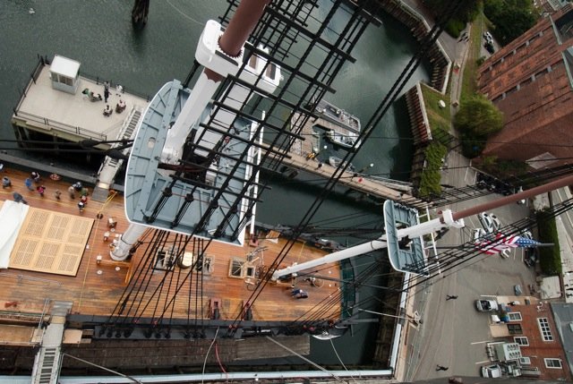
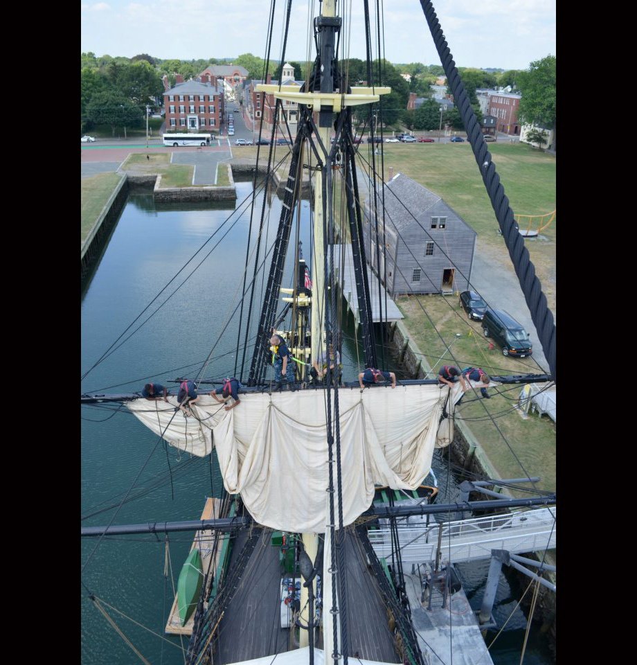
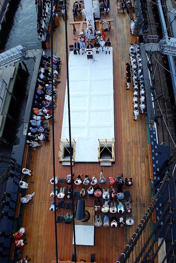
As near as I can tell, the tapering is subtle, but I will check it out in more detail when I get to that stage' Peter, here are a bunch of overhead shots of the stern. Any tapering is hard to see in these photos.
-
When I first started making models around age 10, obviously they were plastic, but I never liked the simple ones. I always chose the ones with the most parts, so most of the time I made modern ships and maybe a few cars and planes. No one I knew made models and therefore I was self taught. I wasn't even aware that you could buy paint. So although, I learned to assemble the kits fairly well they never looked as good as what I saw on the box. Boy, have times changed. Jon
-
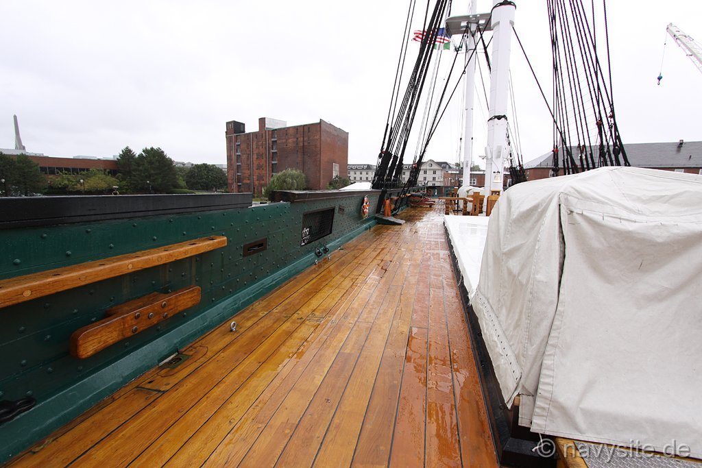
I've been following your conversations from afar about tapering the deck planks and I'm confused. I understand tapering of the hull planks because you're working on a curved surface. Just about every one of my planks near the the bow and stern were tapered. But the only tapering I've seen on the deck planks is where the planks converge and/or nibbed are at the bow. None the of images I've seen of the actual Constitution deck planks converge. Or are you talking about something else? Jon
-
No blood, just the way the wood took the stain. Maybe sweat stain? Jon
-
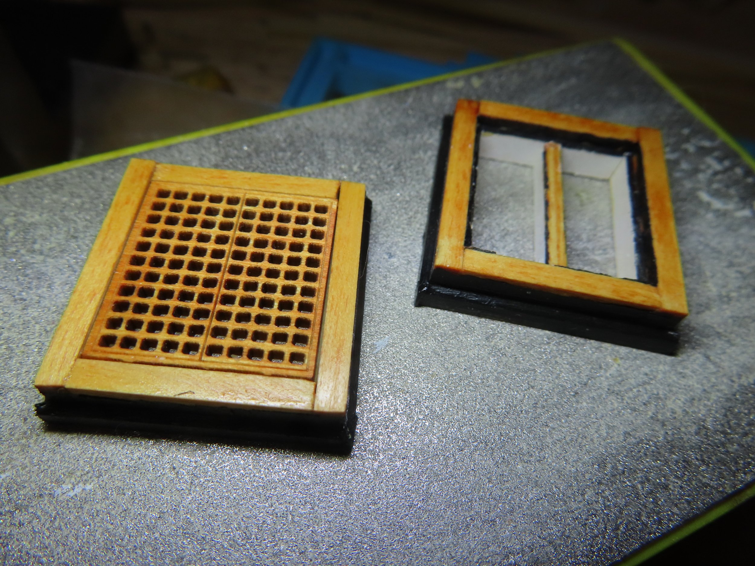
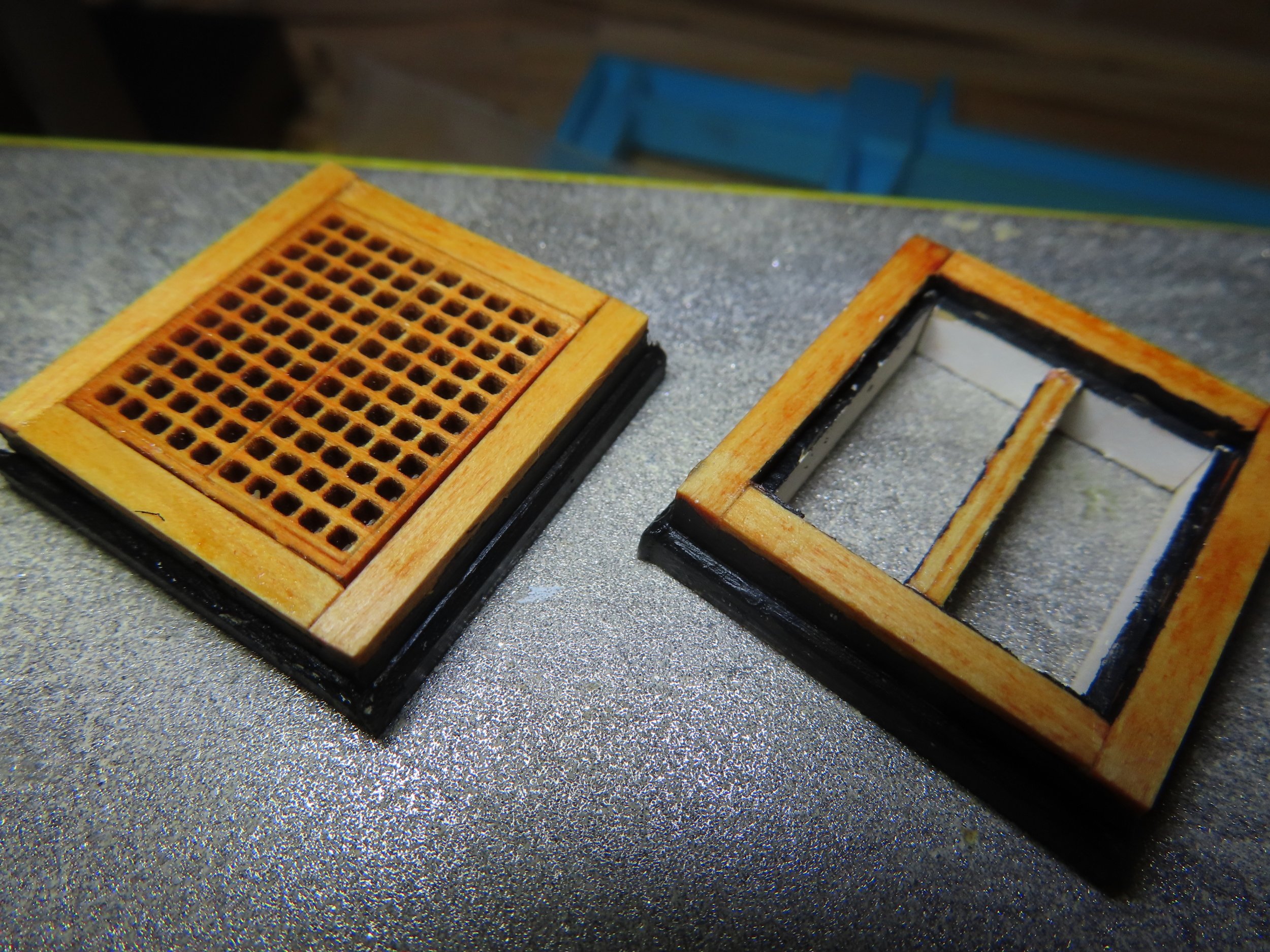
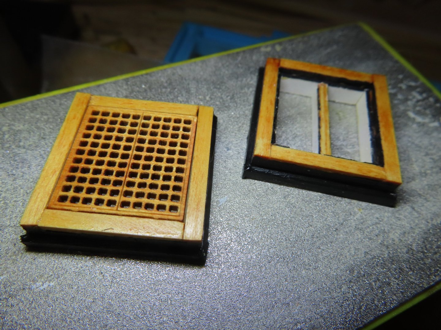
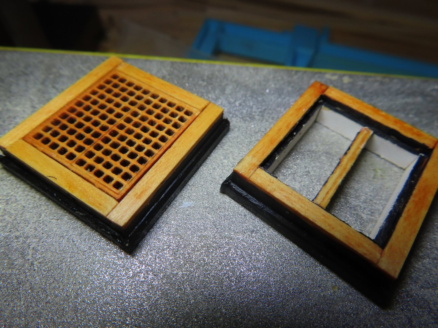
I also noticed that the painting scheme of the actual ship has again changed. You will notice the frames of all the hatchways presently have black trim, whereas prior to the 2015-2017 restoration, the frames had natural wood finishes. Since my model is based on the present ship configuration (with some exceptions), I painted these last two frames with black trim now because the interior elements had to be painted during fabrication and to see how they would look. The others will be painted later.
-
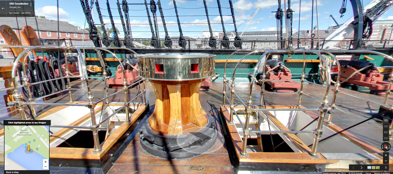
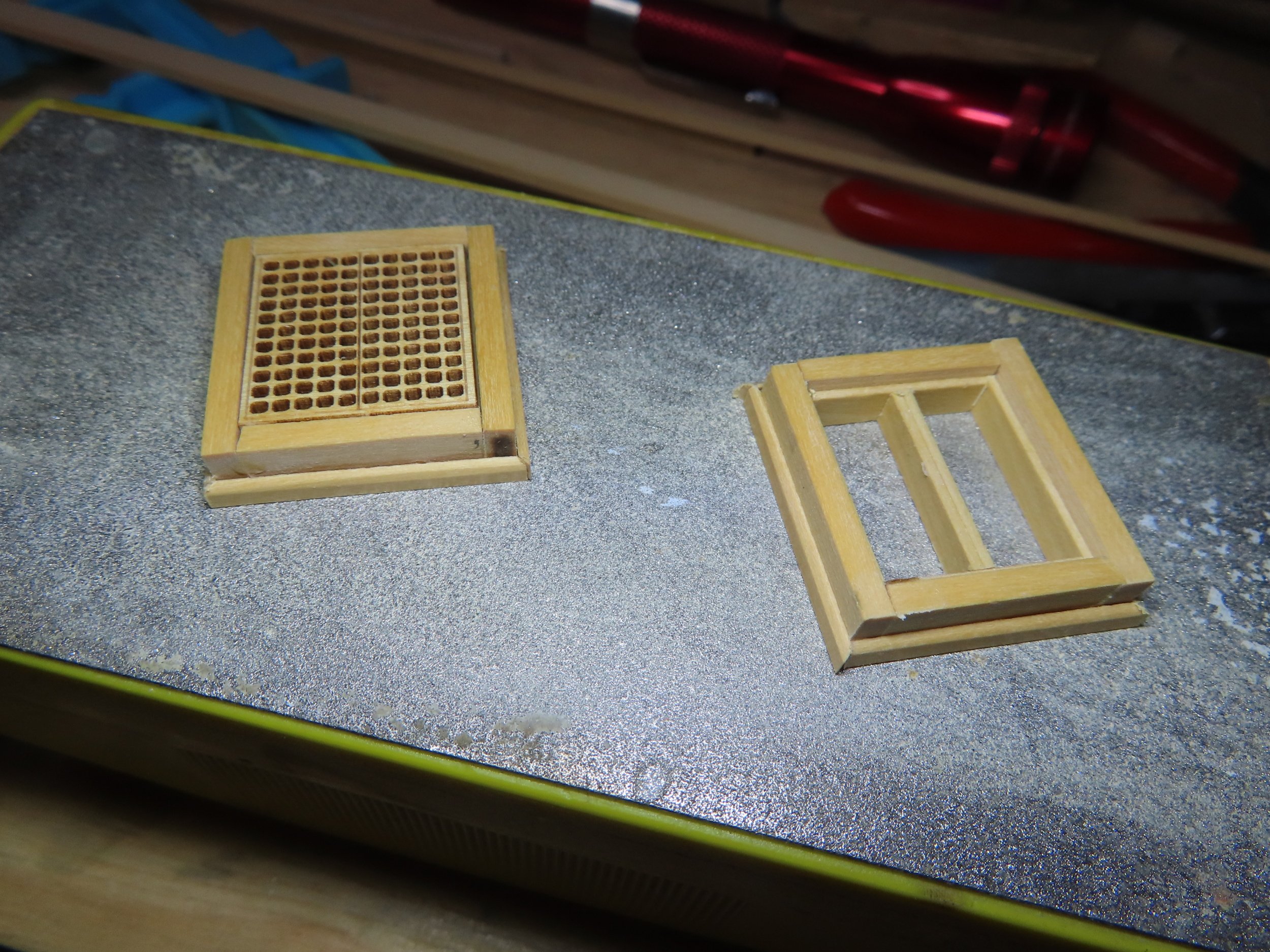
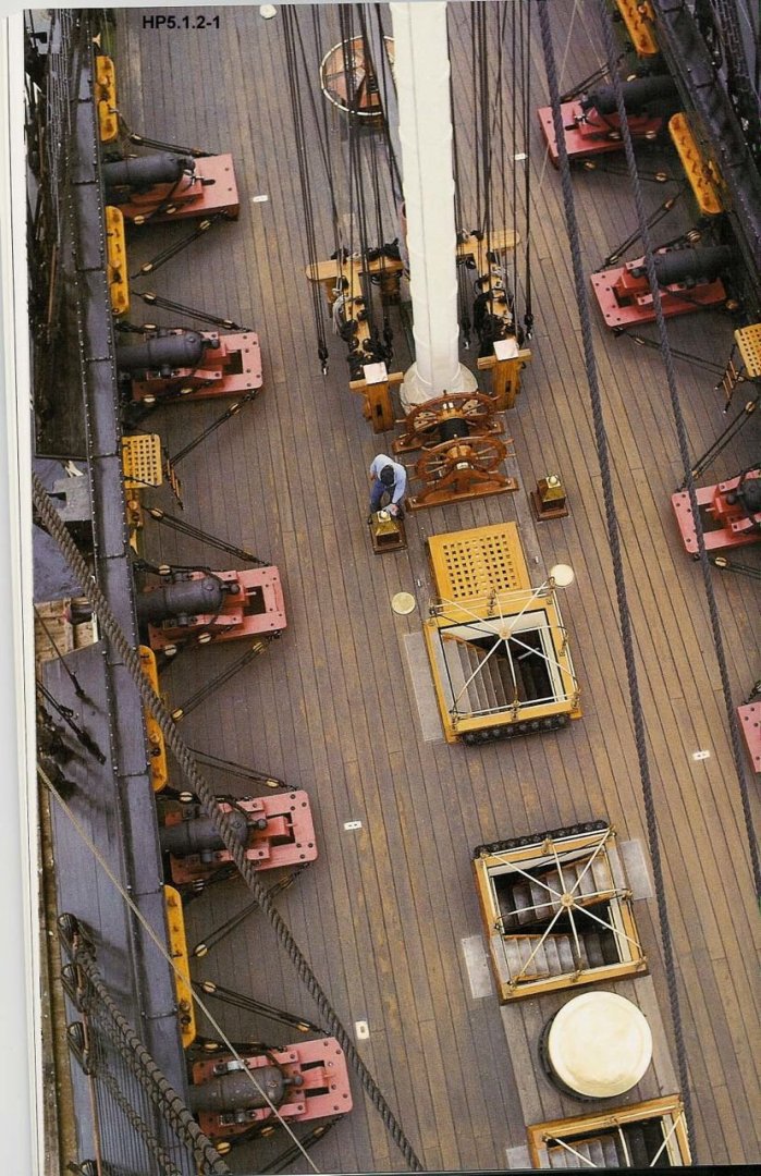
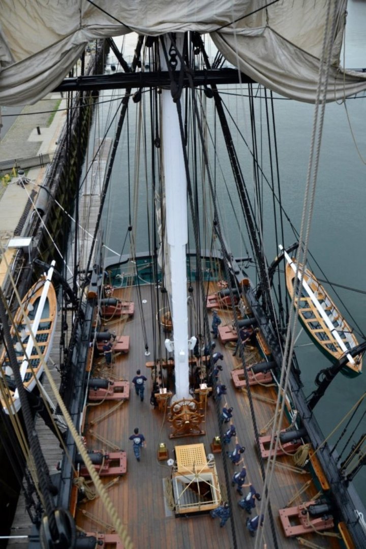
The last hatchways prior to the main one are on either side of the capstan. One hatchway is planned to be open, and the other closed. I found a small discrepancy with the kit gratings. If you look at the actual ship, there are separate gratings for each ladder, four in total. The kit provided two double wide gratings. Maybe they were this way in 1927 which is the main basis for the kit’s design, I don’t know. Whatever the case I’m leaving the closed hatchway as a double wide. The open one looks closely like, but not exactly like individual gratings. The main difference is the center beam between the ladders is flush with the top of the hatchway, whereas mine is sunk down to facilitate the formation of the lip which holds the grating should it me placed back on the frame. The image of the open hatchway is dry fitted pending painting.


-
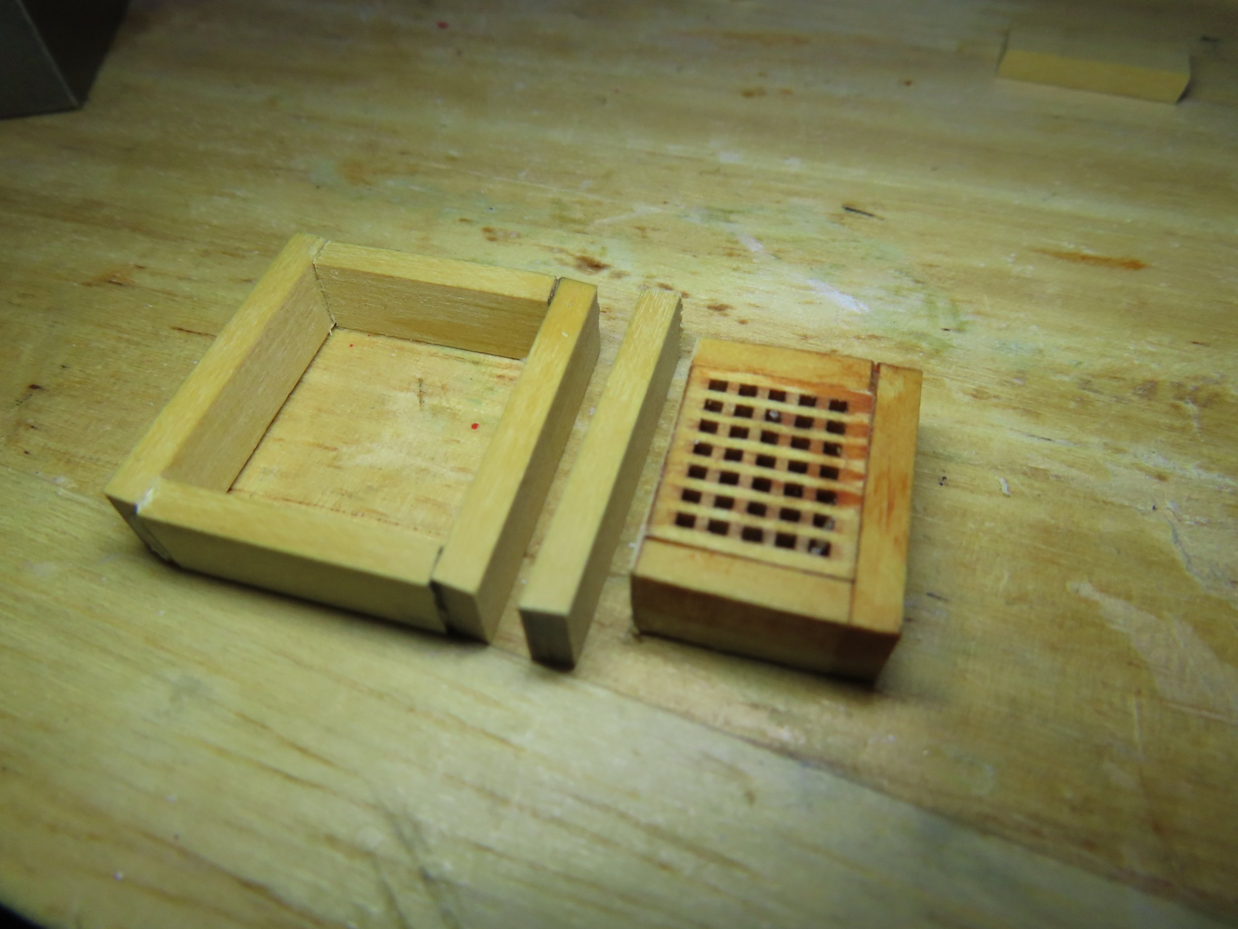
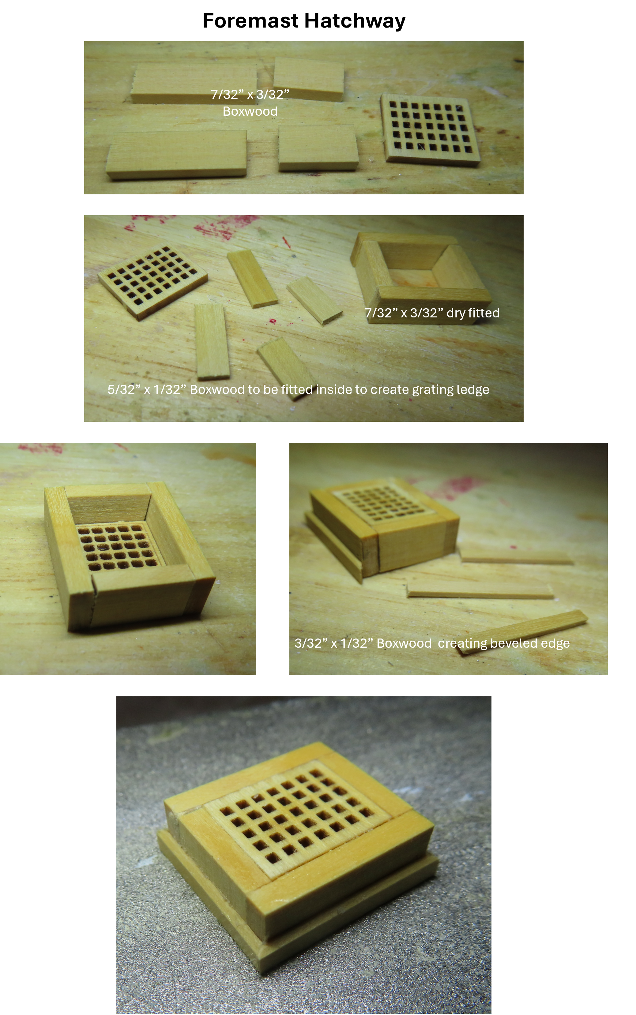
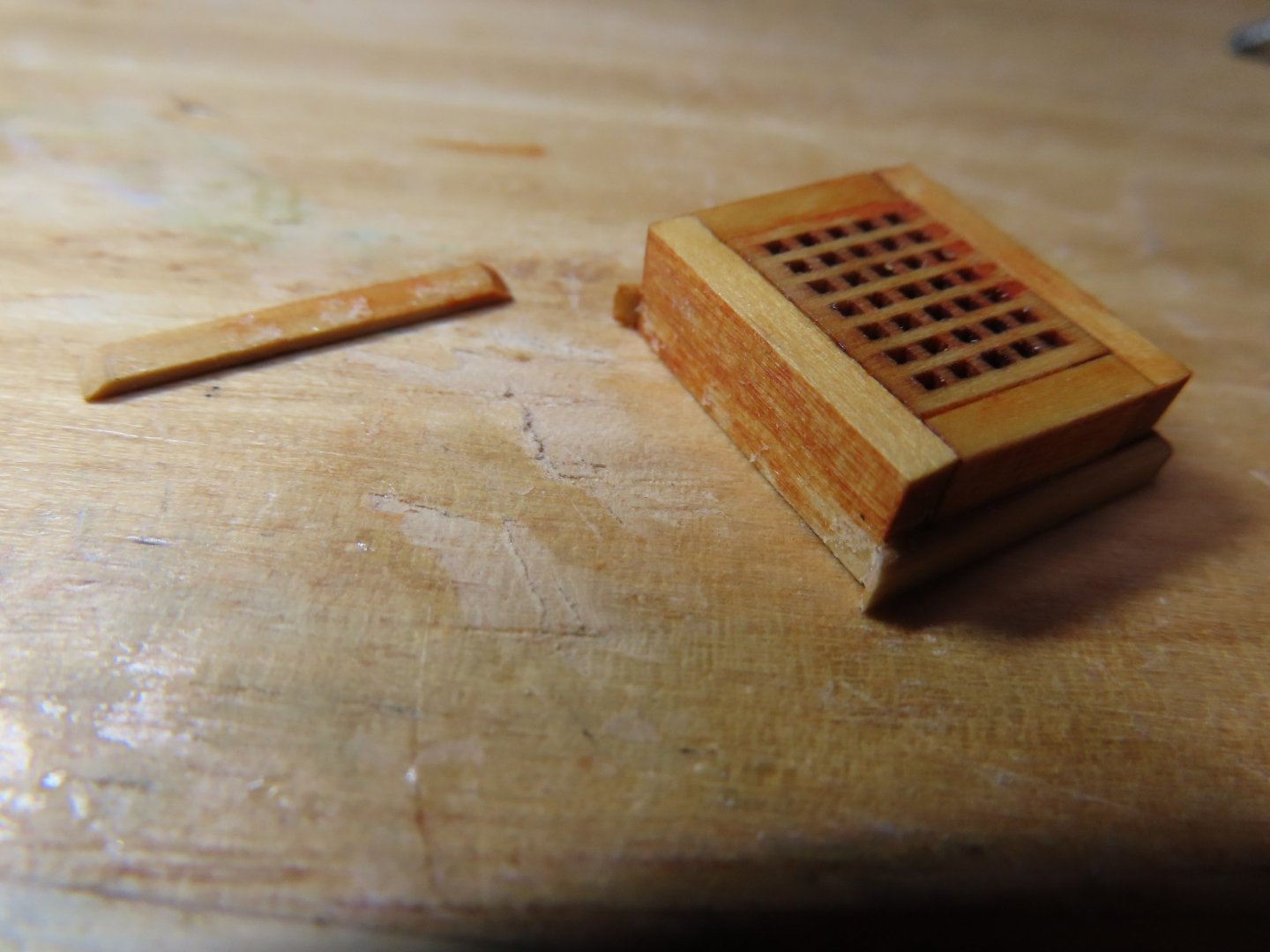
Now for the tricky part, the inside transition curve between the two grating frames. This curve was initially fabricated by trimming off the corners to start the transition. Then, using a router bit on my Dremel tool, the router bit allowed me to carve the inside curve of the 7/32” x 3/32” boxwood using the side of the bit as the cutting tool. This was done by hand, no drill stand or jig was used. To create the curved beveled edging was even tricker due to its size. I was trying to emulate a curved piece of beveled 3/32” x 1/32” boxwood because bending a strip of boxwood 90° in that short of distance was neigh impossible (for me at least). The curve was created by cutting a separate piece of boxwood to the basic shape and finished by carving by hand, again with the router bit fitted Dremel and assorted files. I suppose if I had a milling machine, it would have been more precise, but I think the results I got work just as well.


-
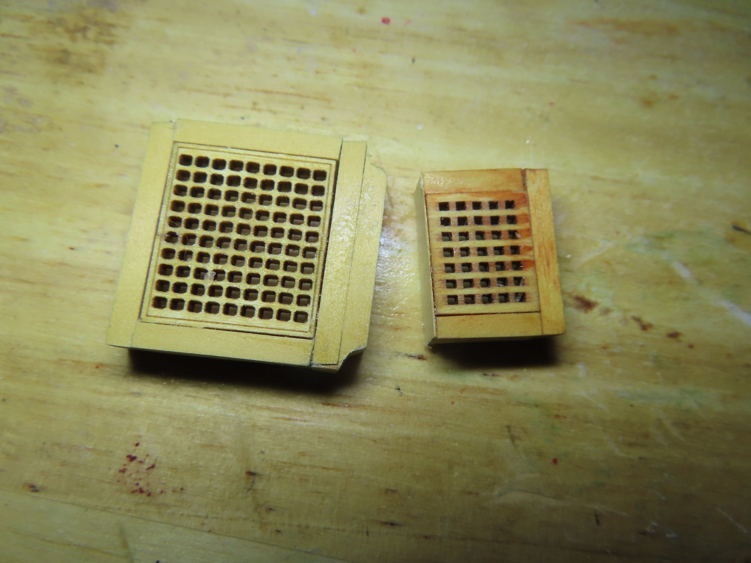
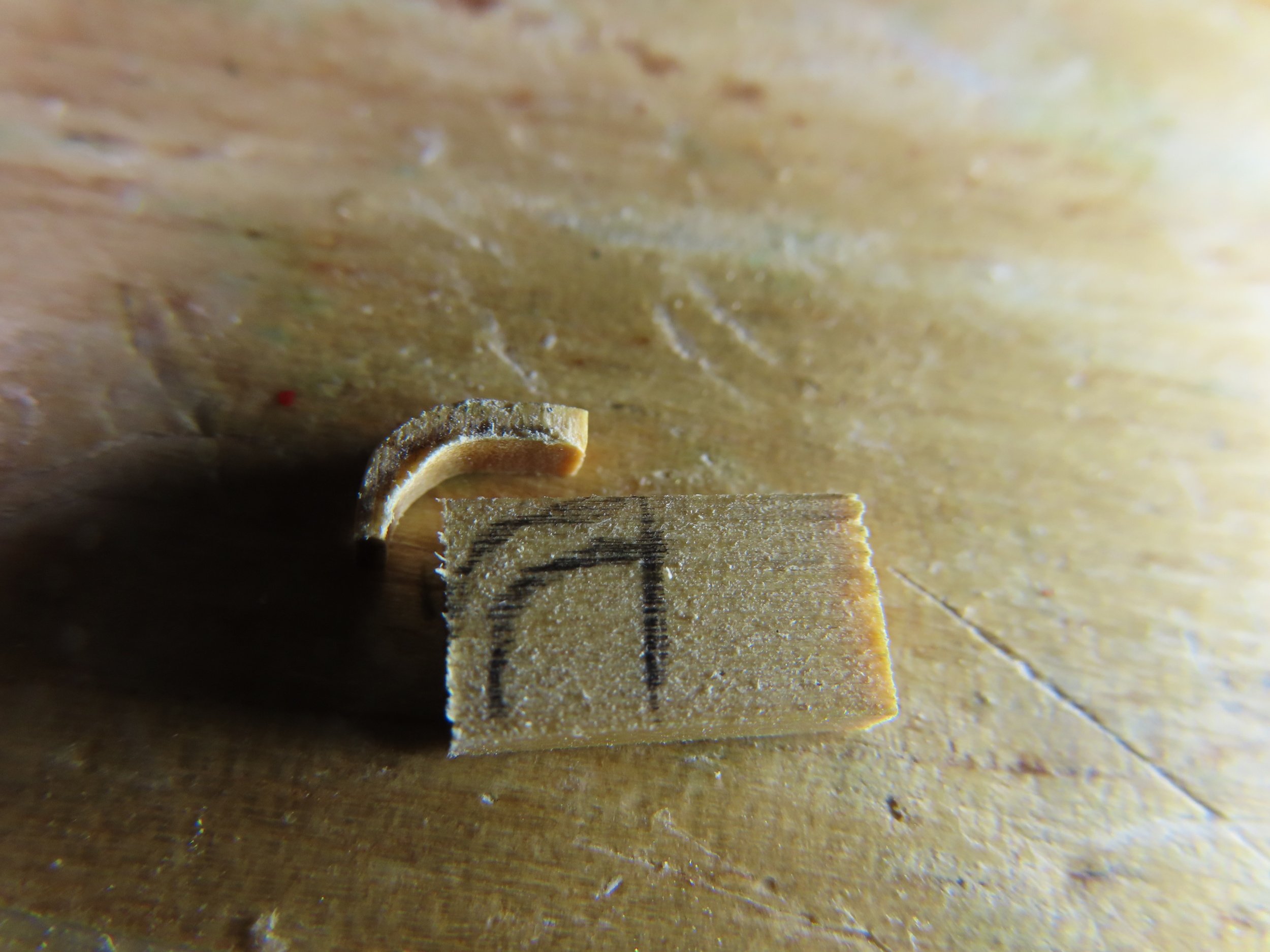
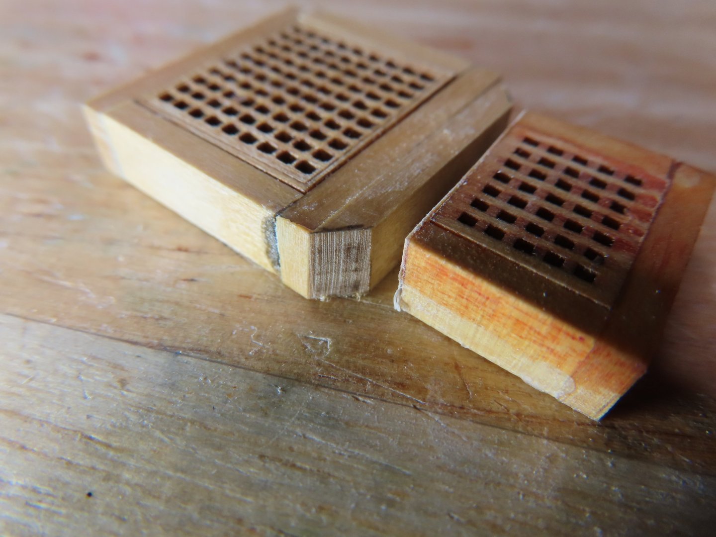
As it turns out, due to the construction of the ship’s wheel double grating, I was able to salvage most of what I had already made. First, I refabricated the foremast hatchway with the proper 7x6 grid grating. (Yeah, I know, no one will know the difference, but I and the man upstairs will). Using the old hatchway, now to become the smaller grating of the double hatchway, I removed all the 3/32” beveled edging from it as well as one wide side of grating 7/32” x 3/32” frame. This piece of the framework was replaced with another 7/32” x 3/32” (the length of the larger hatchway) that was glued to the larger grating frame. This is the piece that will act as the transition between the two gratings.

-
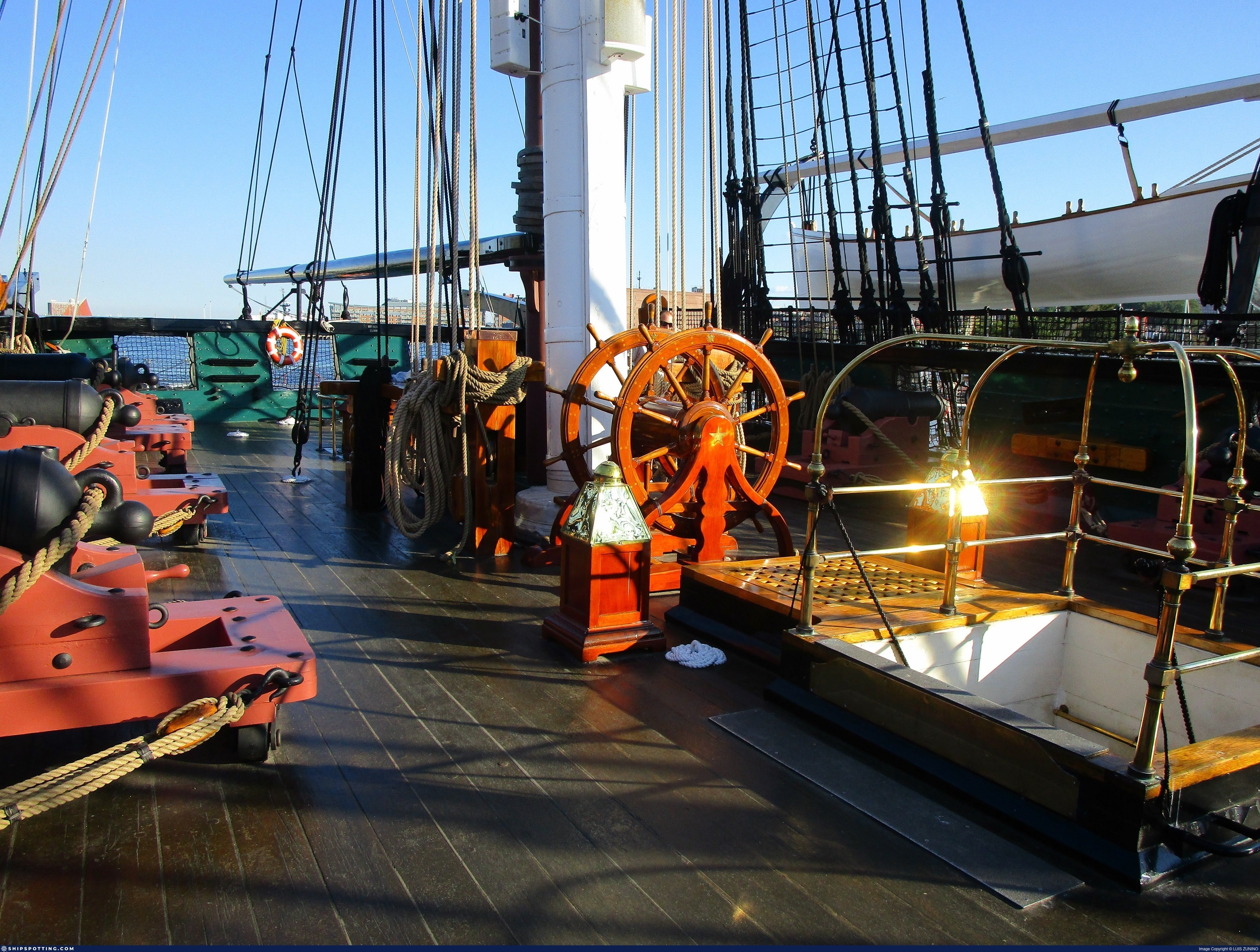
Saving the main hatchways and gratings for last, I worked next on the double grating next to the ship’s wheel. The larger of the two gratings is a hatchway, and the smaller one covers a skylight. I never found an image where that grating was removed to revealed the skylight below. As a matter of fact, I never found a decent image of the double grating as a whole. However, this is where I realized I made a mistake in choosing the kit grating I used for the foremast hatchway. I used the one assigned for the skylight, a 7x5 grid instead of the proper 7x6 grid.


-
I met Ken Foran and to watch him use a metal lathe is a thing of beauty. He's written books, made museum models on commission, etc. To duplicate his process, is out of my league, but it's fun to watch. Jon
-
I've done so much scratch building on my model, that I almost feel guilty when I use a part provided by the kit. Case in point, the kit's cast metal stove stack I used. I really wanted to make my own, but didn't have any idea how to fabricate it with my skills and tools. Jon
-
That's what this site is all about...helping others. Jon
-
In Xken's Niagara log he said: So yes. he mixed his own. Jon
-
I don't think he ever finished it. He did just enough to show how this things could/should be done. Have you noticed, there are no pictures of him rigging the model either once the masts were made. He had too many other models he was working on. Still, without his help, I never would have started my model. Jon
-
I have not had the opportunity to buy wood from Modelers' Sawmill as I have plenty of stock wood. The point I was trying to bring out that HobbyMills was referenced by Mr. Hunt's practicum for Model Shipways USS Constitution supplemental wood packages . Since HobbyMills is no longer in business, I don't know if Mr. Hunt's practicum has been amended to replace HobbyMills as a wood suppler for the packages. Geoff - Thanks for the kudos Jon
-
Gregg, glad to have you as a reader!
-
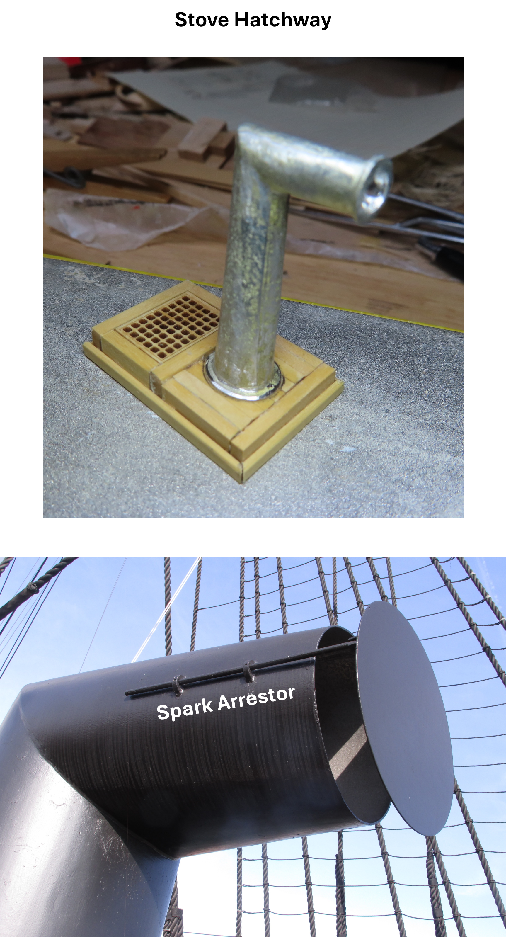
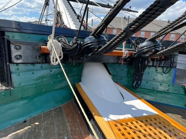
The final touches of adding the arrestor to the stack, eye bolts, shot racks, and painting will be done later, as the main purpose of this exercise was to get the hatchways completed for dry fit up to ensure proper alignment of the spar deck support beams. BTW, the MS plans state that the shot racks on the forward hatchways were not installed in the 1997 restoration. I will install them because I believe they originally existed when the ship was militarily active. Also, I will not install the support beams under the main hatchway that pass under the grating openings. This was where the ship’s supplies were loaded into the holds. Even though she is technically an “active” commissioned warship, these recent modifications, I believe, were made to make the ship more of a museum piece, structurally sound, and for the welfare and safety of tourists. My model is based on the 2015-17 restoration but is not a total replica of that restoration. Still to come are the forward hatchways and the main gratings. [Looking at the stack mouth after I posted these images, I realized the casting had the spark arrestor, but I mistook it for a stack mouth flange. There is no mouth flange, so I will probably remove it when I go to attach my arrestor.]
-
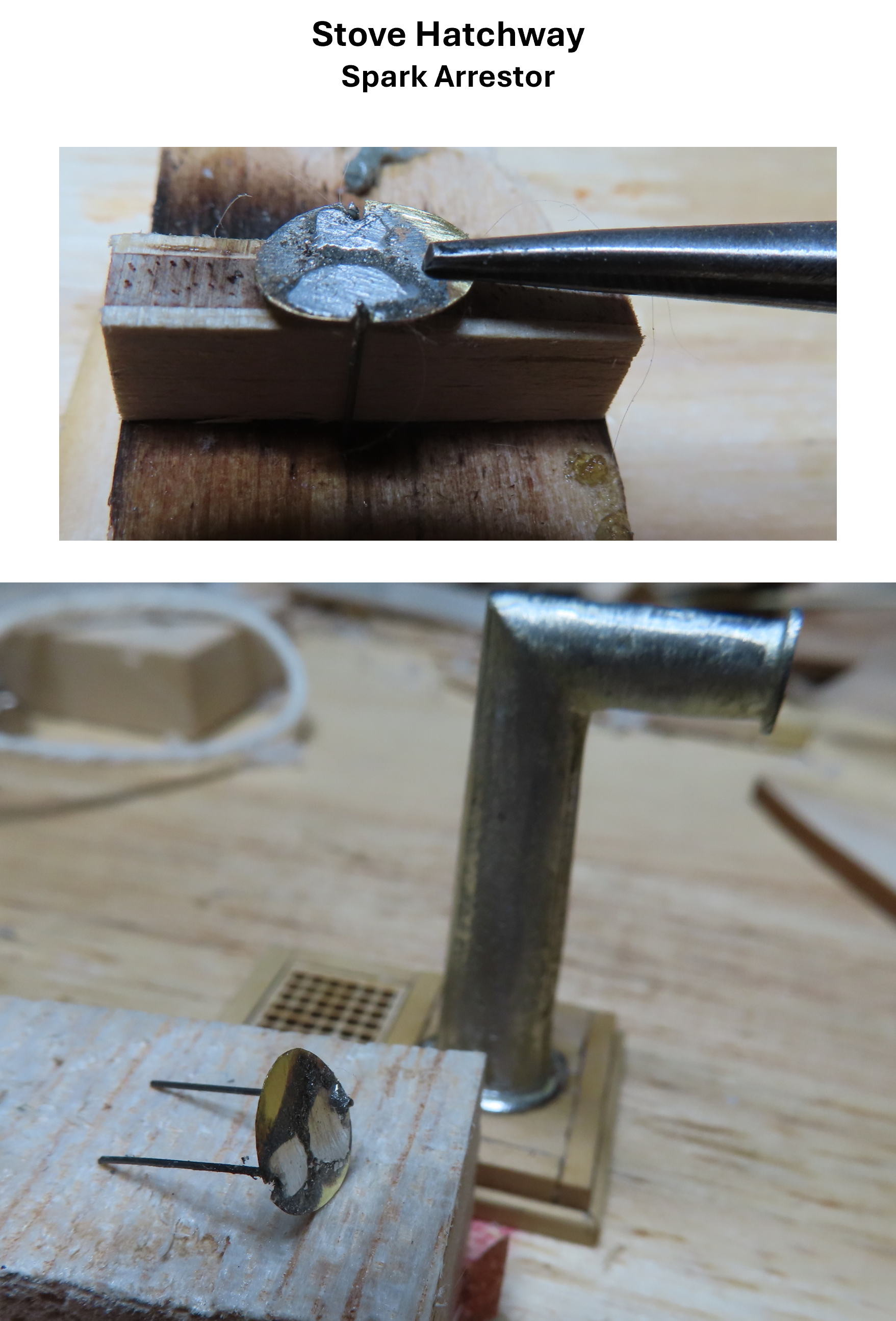
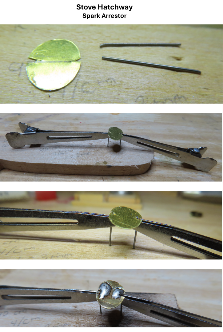
This was a tricky bit. Ideally, I would have drilled a hole on either side of the arrestor plate, inserted some fine diameter rods into the holes and soldered them in place. The immediate problem is that I don’t have a fine drill bit that can drill into metal, even a soft metal like brass. I opted to cut a slit in lieu of holes and hoped the solder would fill in the gaps. I cut 0.005” thick brass place to the oval shape and cut two pieces of 0.018” dia. music wire to length. Using silver solder paste with a butane torch, these were soldered as shown below. It worked like a charm until I tried to remove it from the wood block, and it fell apart. It took numerous attempts and a slightly different, more robust setup, till it held together. The excess solder was then filed off.

-
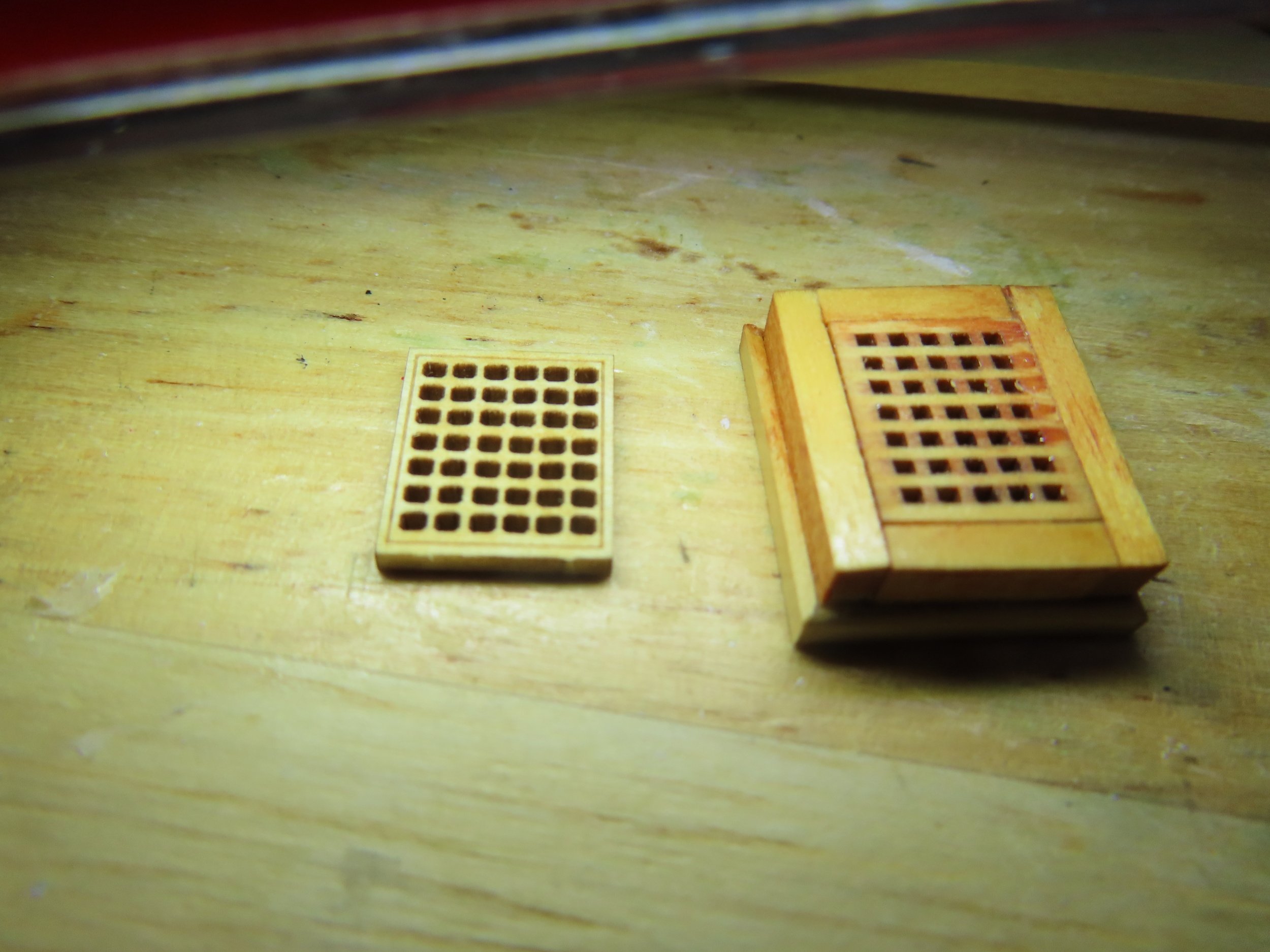
The third hatchway is part of the stove stack. The grating was framed as the others, but the chimney platform section is 1/32” lower with seven 3/32” x 1/32” boxwood planks. The planks are supported just like the grating with an inside ledge. In actuality, the stack passes through the platform to the stove below. My first thought was to recreate the stack using brass tubing, but the stack is oval in cross section, and it tapers towards the top. Even if I had a metal lathe, which I don’t, I have no idea how I would/could fabricate a hollow stack of that shape. The kit’s casting is pretty accurate, so I went with it. Until I removed the kit’s cast stack from the kit box, I thought it would sit flat upon the platform. But the cast piece has a substantial plug/protrusion that requires an oval hole in the slats. If I were to cut/drill a hole through the slats, the platform would collapse. Therefore, I glued a piece of 1/32” plywood under the slats for support. Because this a solid cast part, I drilled out the stack’s mouth just enough to give the illusion the stack pipe was hollow. Of course, just to make things more interesting, the plug is not circular but oval in cross section, and the stack’s base flange is supposed to be recessed into the platform. I decided that the recessed flange was a bit much. A lot of work for not much visual gain and a high probability I could really mess up and have a “re-do” on my hands. The drilling of the plug hole went smoothly. Using successive larger bits, a pilot hole was expanded to the proper width and then filed to get the proper oval shape. A couple of planks tried to come loose but the slight damage was covered up by the stack’s base flange. The next item fabricated for the stack was the spark arrester in front of the stack mouth. It sits very close to the mouth and blocks a direct view inside the mouth enabling my hollow stack illusion.

-
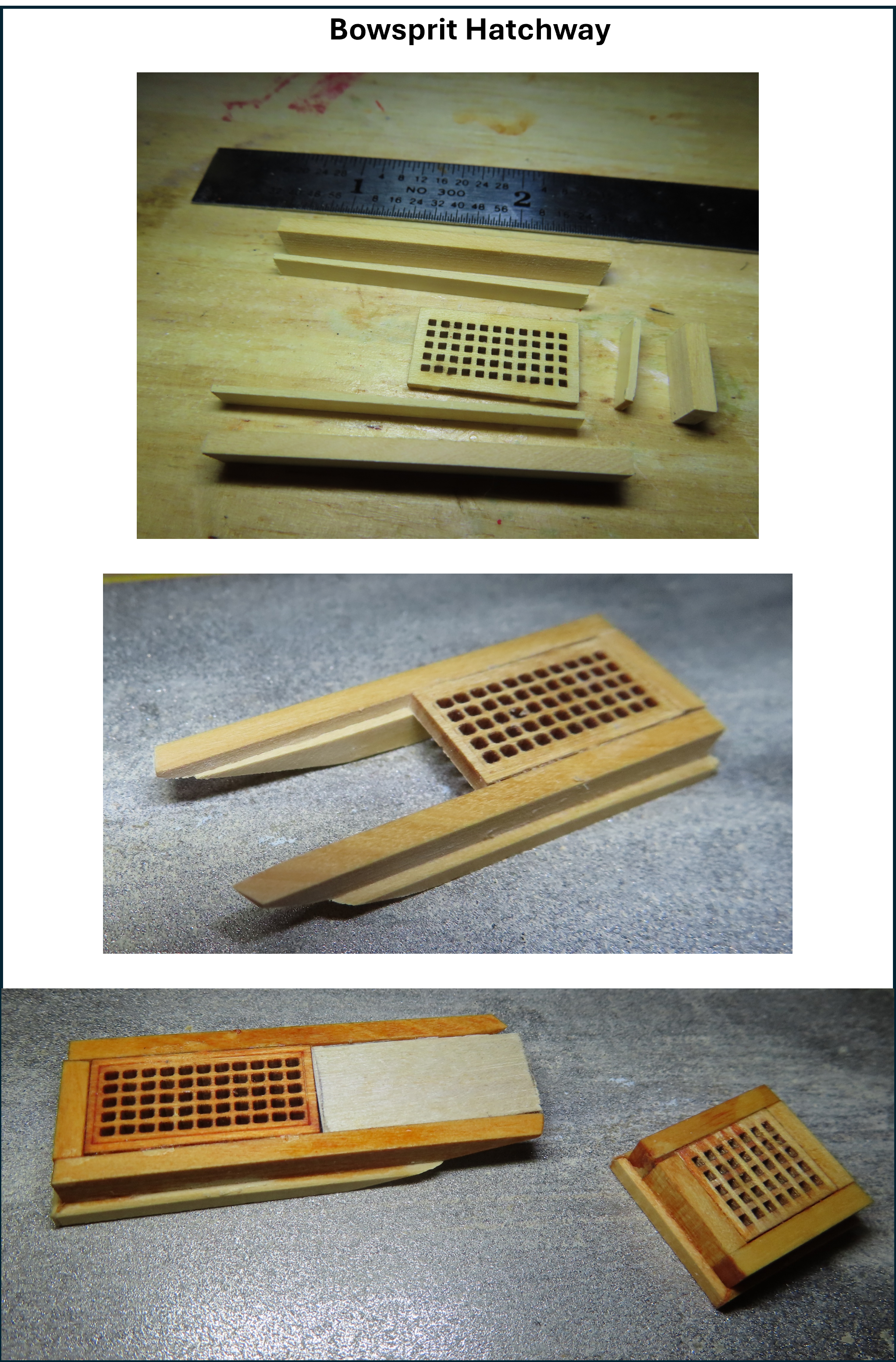
I next chose to make the bowsprit hatchway. This was almost identical to the first one except its sides extended along the bowsprit. Because the sides butted up against the bow waterway, it had to be tapered to fit. In addition, where the hatchway frame extended around the bowsprit, the top covering was cutout to allow the bowsprit to pass through into the deck. I made a blank out of 1/32” plywood to be fitted and painted later.

-
Starting with the small grating frame just forward of the foremast, whose grating supplied by the MS kit measures 15/32” x 13/32”, I cut the 7/32” x 3/32” boxwood stock as follows: 2 pieces: 21/32” lengthwise 2 pieces: 13/32” beam wise These pieces were placed around the grating, framing it with butt joints and glued (not the grating). Then the 5/32” x 1/32” boxwood stock was cut as follows: 2 pieces: 15/32” lengthwise 2 pieces: 11/32” beam wise These were placed inside the and at the bottom of the glued frame. This left the 1/16” ledge at the top for the grating to rest on. Finally, the 3/32” x 1/32” boxwood stock was cut as follows to create a mitered joint, just for looks. 2 pieces: 24/32” lengthwise 2 pieces: 20/32” beam wise The top edge was beveled to a 45° angle and the ends mitered before final assembly.