-
Posts
2,646 -
Joined
-
Last visited
Content Type
Profiles
Forums
Gallery
Events
Everything posted by JSGerson
-
I have the US Navy gun & carriage plans for the Conny should you want them. I have already submitted them to other builders as well. Jon
- 233 replies
-
- Model Shipways
- constitution
-
(and 5 more)
Tagged with:
-
I tried styrene with mixed results. I found that CA glue made the plastic brittle. If I were to do it over again, I would use birchwood strips. Its flexible enough to tie into knots! I don't know if you can find the exact dimensions pre-cut however, so you might have to do that yourself. There are an number of suppliers on the web. Jon
-

USS Constitution by mtbediz - 1:76
JSGerson replied to mtbediz's topic in - Build logs for subjects built 1751 - 1800
My vote is for the dark gray. Jon -

USS Constitution by mtbediz - 1:76
JSGerson replied to mtbediz's topic in - Build logs for subjects built 1751 - 1800
I am by no means an expert on "blackening," but it appears to me that the brass may still have had some fine residual oil remaining on the metal from the turning or casting process (which ever was used) or even your fingers. I usually clean the metal with acetone first. You may have done that, in which case try rubbing off the blackening, This may absorb what ever substance is covering those bare spots. Clean once more with acetone and blacken again. Still no luck? Then you presented the choices yourself, keep or paint. The argument for paint is that the rest of the ship looks pristine, fresh out of shipyard and the paint will make the guns look new. But I do like the weathered look that you achieved. I don't know if I helped or hindered. Jon -
I checked the US Navy plans and got the following gun lengths: Carronades: British Style: 5' 1 7/8" => scale: 0.81" (13/16") or 20.5 mm 1812 Style: 5' 5" => scale: 0.85" (27/32") or 21.6 mm 32 pdr: 10' 9 1/8" => scale: 1.7" (1 45/64") or 43.2 mm 24 pdr: 10' 1 1/4" => scale: 1.6" (39/64") or 40.6 mm Jon
-
I hadn't discussed the carronades on my blog yet because I'm not there yet. I purchased all the 1812 carronades for the spar deck from Model Monkey a year or so back. They 3-D printed parts specifically for the 76.8 scale MS kit and they weren't cheap. In this case they printed the complete carronade barrel and carriage as one unit. I would have preferred just the barrel and fabricate the carriages myself. We'll see if I can split them apart when the time comes. However, the bad news is I didn't see those items on their web page when I checked today (1/5/25). Of course, I have the US Navy plans for both versions of the carronades should anyone want them.
-
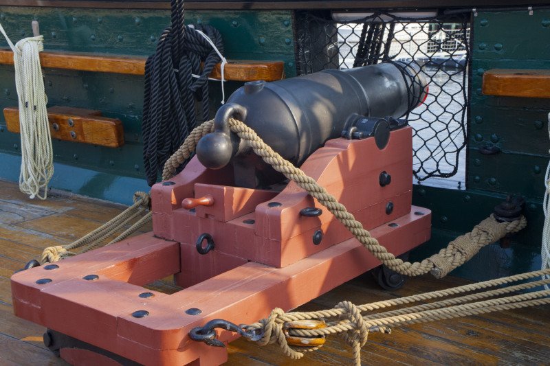
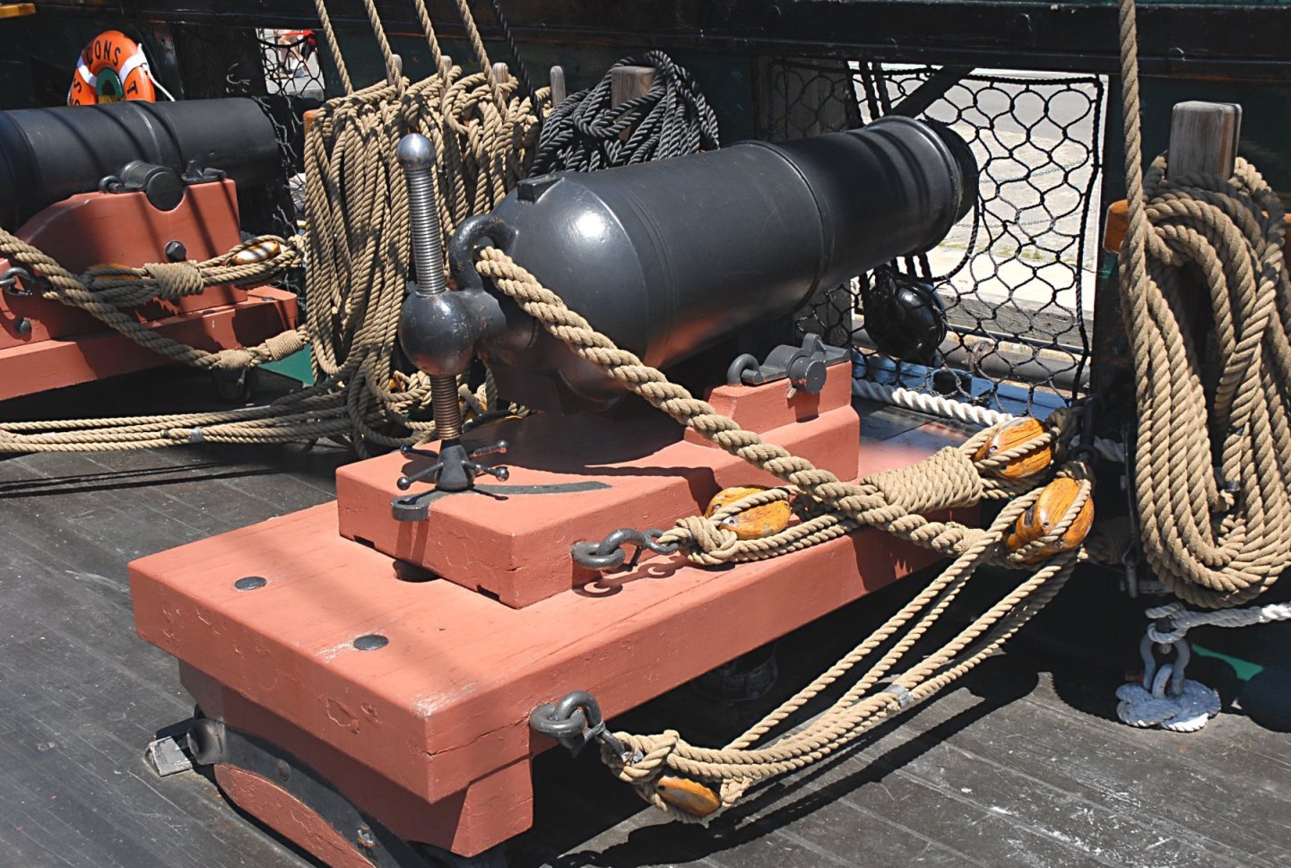
Ah yes, the carronades. Here is a "blurb" from the USS Constitution Museum: Below are images of the inaccurate British siege gun and the more accurate 812-era replica carronades. the one with the screw barrel elevator. I elected to place the more accurate 1812 version on my model. Others have decided to use the siege gun version because that is what is on the ship today save for the two 1812 replicas. The two version require different carriage designs. The choice is yours. Jon
-
Again, you did an amazing job on those handrails, which BTW I am working on mine now. You got that ring absolutely round, and the ends meet with perfect closure. I cannot tell from the photo were the ends meet. How did you line up the ring with the perfectly vertical supports, hold them in precise alignment to apply, what I assume is CA glue? What's also amazing is there is such little surface between the mating surfaces for the pieces for the glue to adhere to. A job very well done!! Jon
-
You are not the first to run into this cannon height problem. Myself and another builder (forgive me, I've forgotten which one, it's been a while) had the same problem building the Model Shipway's model. The gun deck was not part of the kit so it was my first kit bash without instructions. We purchased additional guns and carriages from Model Expo. As it turn out the Model Expo gun carriages did not match the dimensions of the US Navy USS Constitution plans. They were too short. The other builder elected to split the sides of the carriages and add addition wood to raise the height. I elected to fabricate the carriages from scratch using the US Plans. In my case, that was 22 gun carriages that were visible and therefore affected (the remaining 8 guns were dummies). Raising the deck was not an option for me by the time I addressed the problem. Yes, I'm a glutton for punishment!😁 Looking forward to seeing how your solution works out, hopefully for the better. Jon
-
Peter, The US Navy plans I have. The 3-D printer I don't have, nor do I know of anyone who does have one. Cutting the brass 1/16" stock or the styrene 0.060" stock into cubes wasn't a real problem if you have a small miter box and a fine tooth saw. Cutting the brass rod and tubes also not a big deal. I used a fine tooth saw because if I used a cutting disk on a Dremel tool, the tiny piece pieces would fly off into Never-Never Land. I bought the brass balls. The hard part (for me at least), was trying to drill holes into the brass as I have documented. Take it one step at a time, and it will come together. Albeit, there are a lot of steps. As for going to a larger scale, the 1:76 scale of the MS kit creates a four foot model. That in turn requires an even larger display box, which requires a display table large enough to properly show off the display box. Now increase the scale of the model and everything gets bigger. Oh, one other thing, usually a larger scale almost demands more detail. Be careful what you wish for.🤥 If you enjoy it, it not work Jon
-
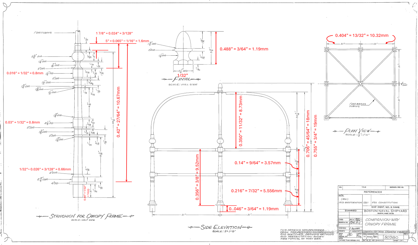
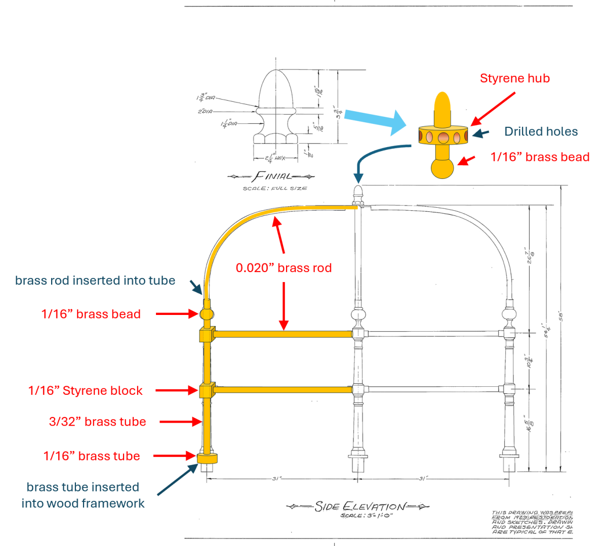
I am taking my canopy frame fabrication cues from several builders but am using 1/32” brass tube instead of 1/32” brass rod as many other builders have used for the vertical components. This allows me to use a continuous vertical component, passing through the junction blocks and decorative balls to just beyond the top railing. Then the overhead canopy support made of 0.02” brass rod can be inserted into the 1/32” tube creating a strong mechanical connection. The 0.06” blocks will only support the horizontal rails with no stress. The brass balls are strictly ornamental and provide no support. The tricky part is where the canopy arches all meet at the top. A hub piece will be used to connect all the arches plus the finial. The finial is to be comprised of a rod and tube configuration (TBD), and filed into its final shape and inserted into the hub. The vertical framework base will be inserted into rings made from 1/16” tubes, embedded into the grating wood frames. Here is a summary of the materials: Base of vertical component: 1/16” brass tube – K&S Engineering No. 5125 Vertical component: 1/32” brass tube– K&S Engineering No. 815035 Horizontal component: 1/32” brass rod - K&S Engineering No. Junction blocks: 0.06” Styrene square rod – Evergreen No. 223 Ornament: 1/32” brass balls – Tribal Desert from Etsy Junction hub: 3/32” styrene tube – Evergreen No. 153 So here is my plan based on the US Navy plans and the trial prototypes of the vertical components and the canopy hub element to see if this would work. The prototype is purely concept, so it is not adjusted for proper dimensions or glued and yet it stands on its own. The final image shows the styrene painted brass. It appears it just might work.
-

USS Constitution by mtbediz - 1:76
JSGerson replied to mtbediz's topic in - Build logs for subjects built 1751 - 1800
I'll add that to my list of a metal lathe, 3-D printer, router, and dedicated drill press.😁 -

USS Constitution by mtbediz - 1:76
JSGerson replied to mtbediz's topic in - Build logs for subjects built 1751 - 1800
As always, fantastic woodworking skills. Well done! Jon -
Peter, Ken Forman (xKen) is a master of metal work, so he made his scroll work out brass plate and solder and he did a beautiful job. Like him, my scroll work was fabricated from smaller pieces but I used 1/64" boxwood instead metal. I actually wanted to carve finer detail into the scroll work, but I didn't have the skills or tools to get the effect I wanted. But, from a foot away, the results were acceptable. I actually found creating the fiddlehead and the cheek knees much more difficult and I wasn't fully satisfied with those results either. Take your time, make trial pieces, and have patience and tenacity, and I have faith you'll will get it done. Jon
-
I really don't know where the problem lies, my technique, proper type of tools, quality of tools, or my skills. The one thing I couldn't try was a slower drill speed. My old Dremel drill press can only accept my one speed plug-in Dremel drill and not my cordless variable speed Dremel. I think it will work out OK with using Styrene for this one component. Jon
-
Another quick update on brass drilling. Yes, the new bits drilled through the brass...until they didn't. If you look back, I made a diagram of how I was going to the drill brass blocks. Basically, each block requires two holes, some passing all the way through the block, and others only halfway. Each block required two set ups on the drill press. I was lucky if my new drill bits lasted two blocks before they quickly dulled up or broke. On moment they were drilling, the next they weren't. One didn't even drill from the start. I actually bought bits from three sources, my original bits from either Model Expo or Micro-Mark, a full set from AliExpress, and two Gyros #75 packages and one Gyros #67 each containing 12 bits/pkg. The AliExpress #67 bit broke immediately upon touching the brass and the #75 went dull. The Gyros went dull after a couple of holes. I was using a light touch, not jamming the drill into the brass. After all this, I don't have much to show for my efforts, just two cleanly drilled brass blocks. So I will admit defeat and go to plan B, Styrene plastic. The drill bits cut through in seconds, and cutting the blocks off from the bar requires just a sharp knife instead of a fine tooth saw or cutting disk. Hopefully, the brass painted blocks will blend in with all the brass rod that make up the canopies.
-
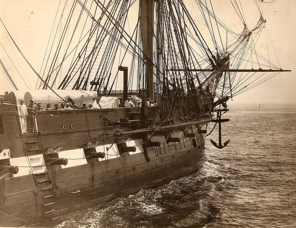
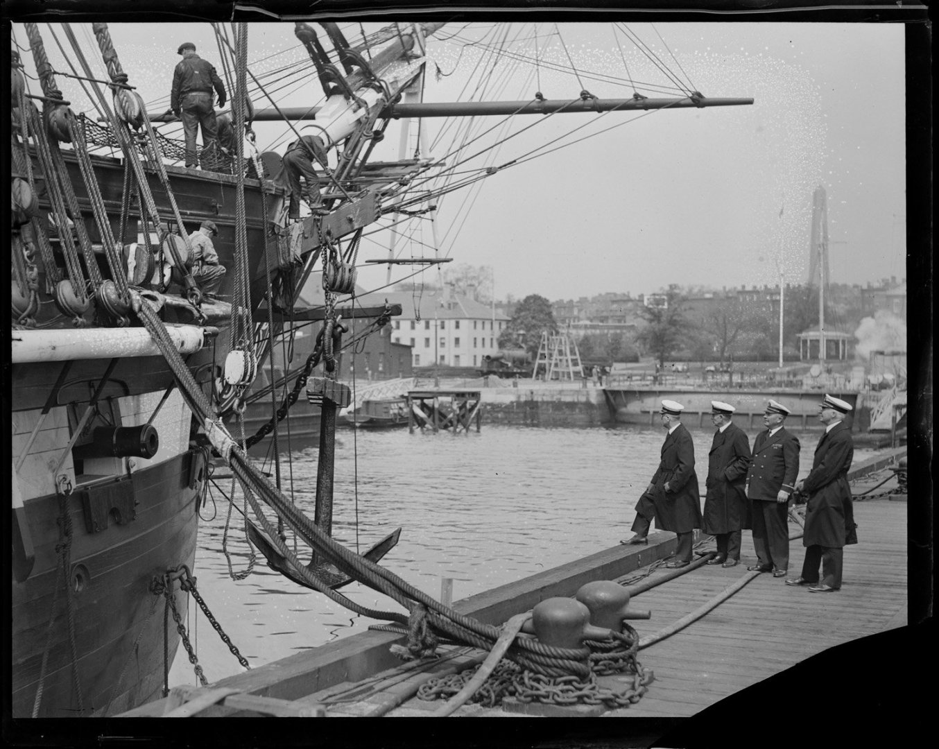
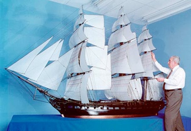
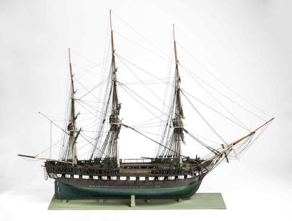
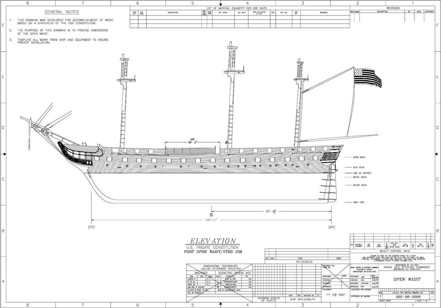
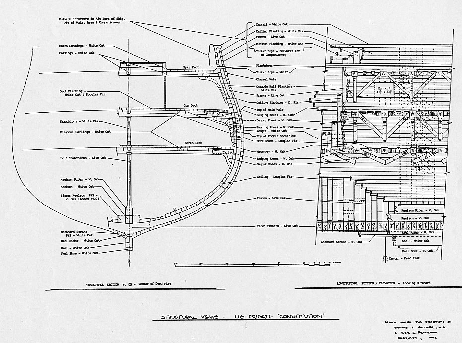
TBE - I have Olof A. Eriksen's book Constitution - All Sails Up and Flying that you linked to in your post, but the link was for the whole book excerpt and not anything specific, so I don't know what specifically you wanted me to see. The book deals and rigging and sails, with a little history, and not so much the structure of the ship. He also has a few photos of his various models of the Constitution. His masterpiece was his 1:24 1812 scale model. Unfortunately I could not find any detail photos of his models. The USS Constitution Museum talks about the 1812 Hull model exhibited in the Peabody Essex Museum. Although the Peabody Museum does not show any images of this exhibit, a good collection of them can be found at Fine Scale Modeler Magazine's website. I have found a few more images over the years. The open waist was reintroduced by the US Navy with this plan below. It was an attempt to return to the 1812 configuration. The 1992 cross section plan showing the waterway and plank sheer was drawn the same time the open waist returned. You could use this as a guide. I am not an historical expert, but I just have a lot of "stuff." Nobody really knows what the ship looked in her early days, just educated guesses, so you have some artistic freedom. As I have always said, your making a model of the ship, not a miniature reconstruction. I hopes this helps Jon
-
The topgallant rail was added during the 1927-31 restoration. It was subsequently removed during the 2007 -10 restoration (I believe) after it was determined to be historical inaccurate. The MS kit is based on the 1927-31 restoration which why its part of the MS model. So, all USS Constitution builders must decide what era their model represents...the earlier in the build the better. Jon
-
I met Ken (a professional model builder) and his wife at the 2016 NRG conference in San Diego CA while he was still building his USS Constitution model (you'll find my two cents comments and contributions in his build log). Since he finished that build he designed, built the prototype, and wrote the manual for the Model Shipways' USS Constitution cross section model kit. And to top that off he did the same for the Model Trailways 1869 Allerton Steam Fire Pumper. He also written a couple of books on how to machine brass parts on a mill and lathe. He is an awfully nice guy and would probably answer any questions posed to him, but I doubt he still follows Conny build logs because he moved on to other projects. Jon
About us
Modelshipworld - Advancing Ship Modeling through Research
SSL Secured
Your security is important for us so this Website is SSL-Secured
NRG Mailing Address
Nautical Research Guild
237 South Lincoln Street
Westmont IL, 60559-1917
Model Ship World ® and the MSW logo are Registered Trademarks, and belong to the Nautical Research Guild (United States Patent and Trademark Office: No. 6,929,264 & No. 6,929,274, registered Dec. 20, 2022)
Helpful Links
About the NRG
If you enjoy building ship models that are historically accurate as well as beautiful, then The Nautical Research Guild (NRG) is just right for you.
The Guild is a non-profit educational organization whose mission is to “Advance Ship Modeling Through Research”. We provide support to our members in their efforts to raise the quality of their model ships.
The Nautical Research Guild has published our world-renowned quarterly magazine, The Nautical Research Journal, since 1955. The pages of the Journal are full of articles by accomplished ship modelers who show you how they create those exquisite details on their models, and by maritime historians who show you the correct details to build. The Journal is available in both print and digital editions. Go to the NRG web site (www.thenrg.org) to download a complimentary digital copy of the Journal. The NRG also publishes plan sets, books and compilations of back issues of the Journal and the former Ships in Scale and Model Ship Builder magazines.




andmooringchains.jpg.0df7eb2599f2e92128e3a961b91b72b1.jpg)
