JSGerson
-
Posts
2,646 -
Joined
-
Last visited
Content Type
Profiles
Forums
Gallery
Events
Everything posted by JSGerson
-
 She's turning into a very handsome model! Jon
 -
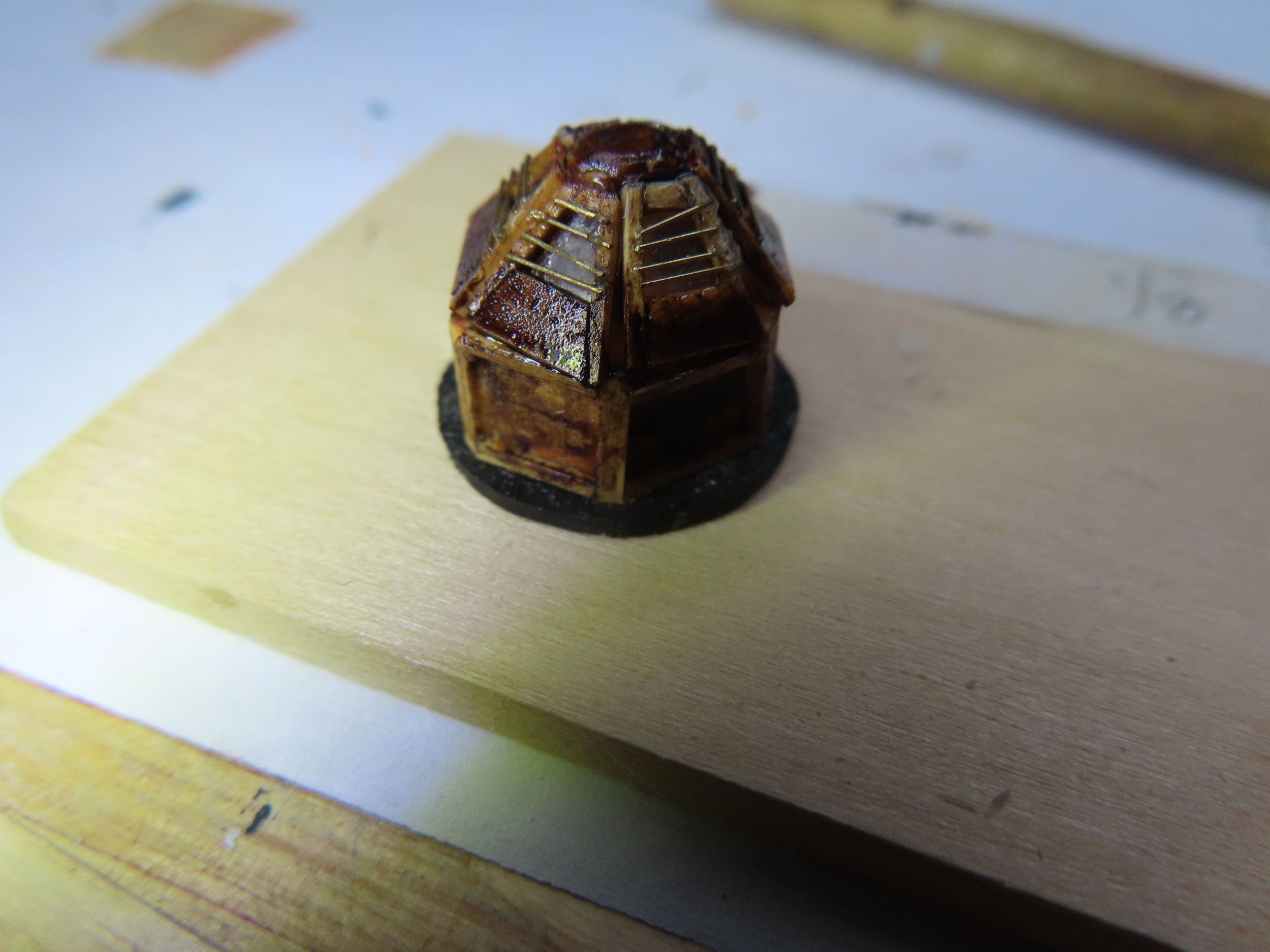
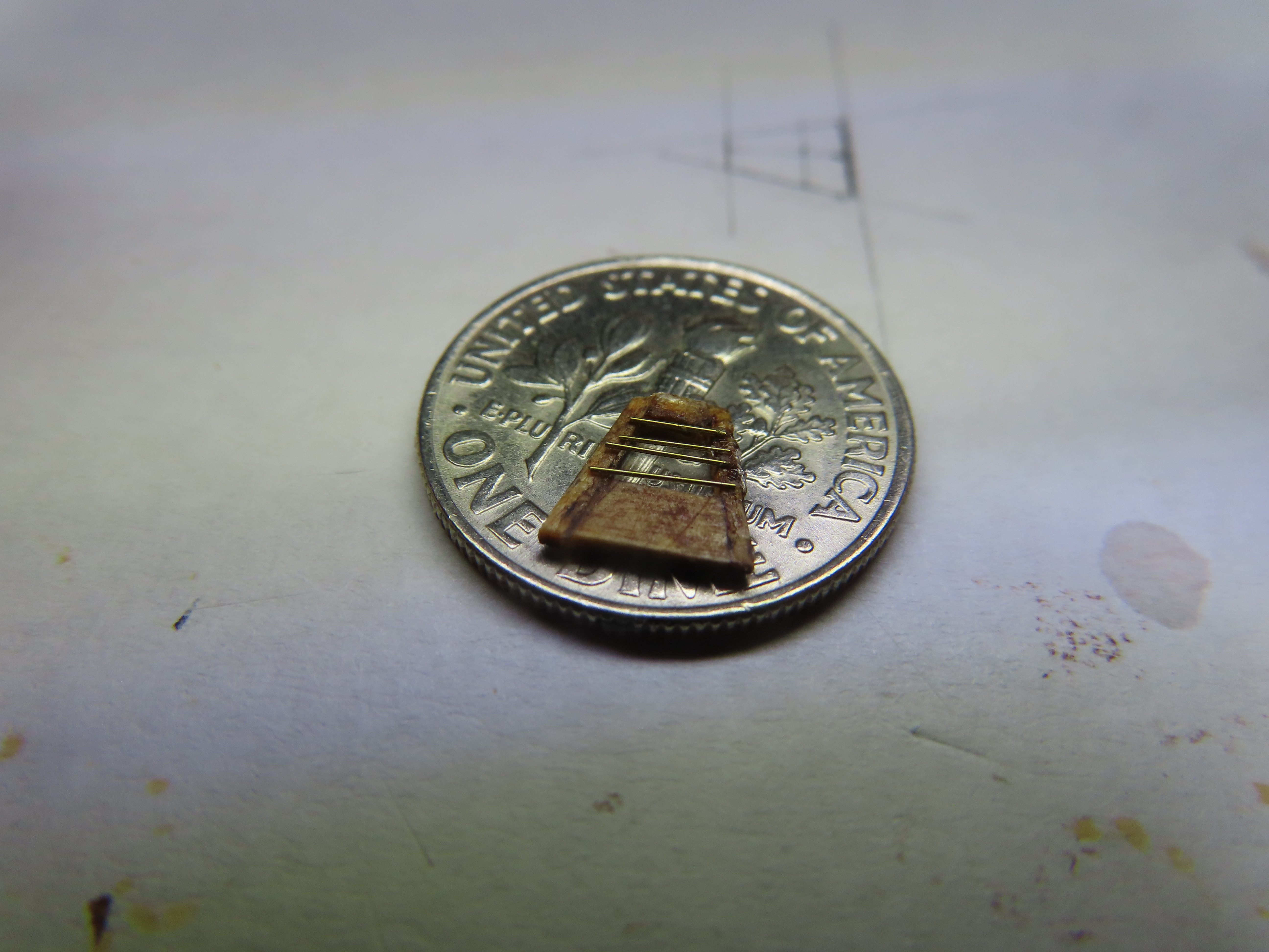
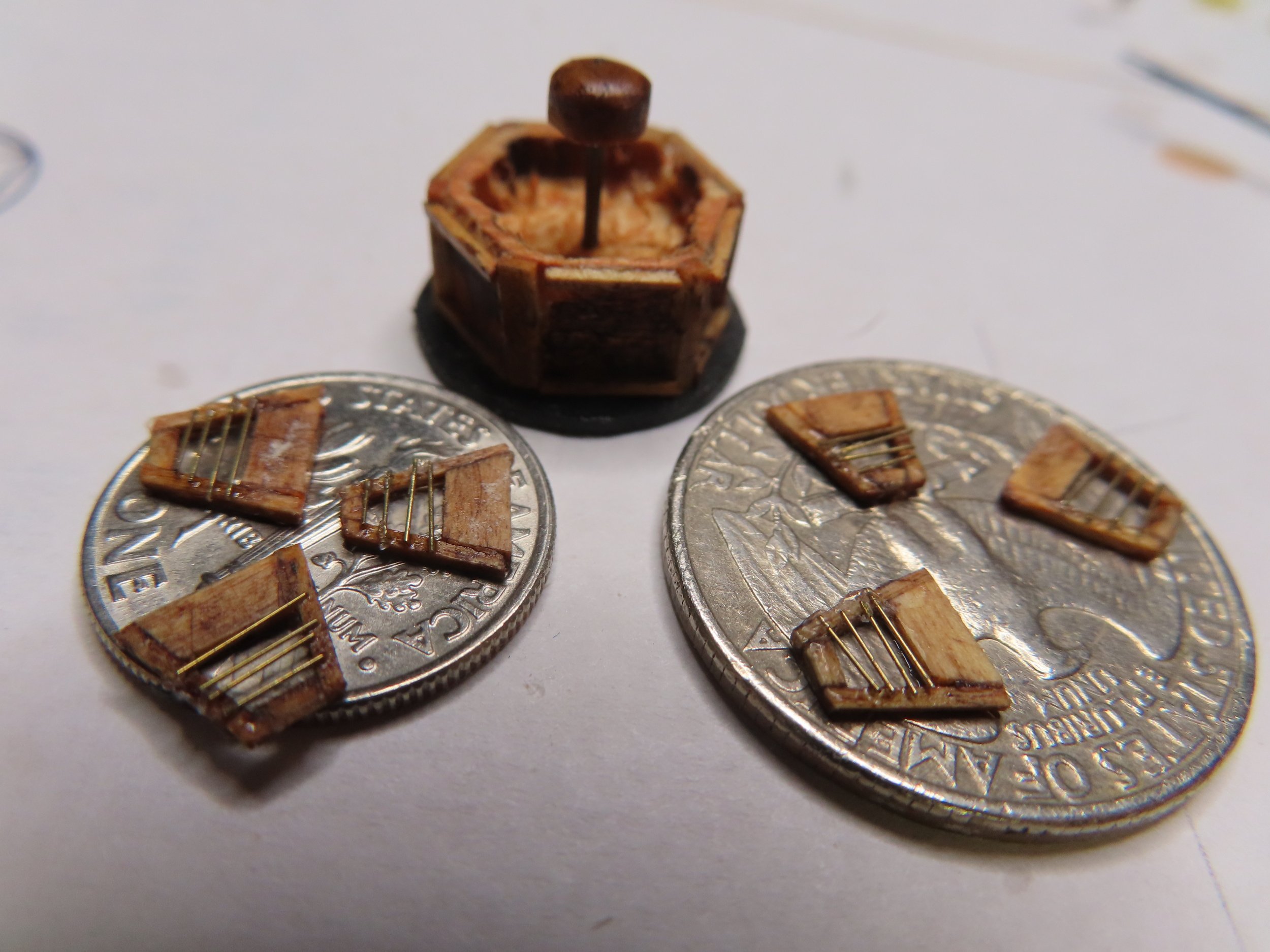
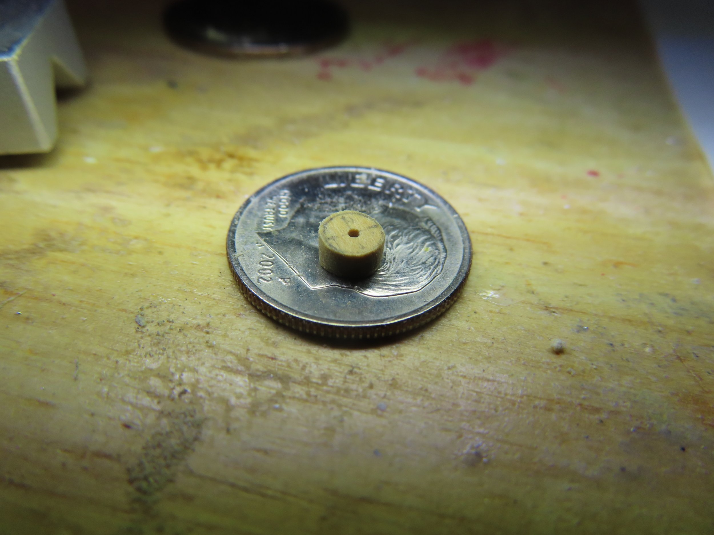
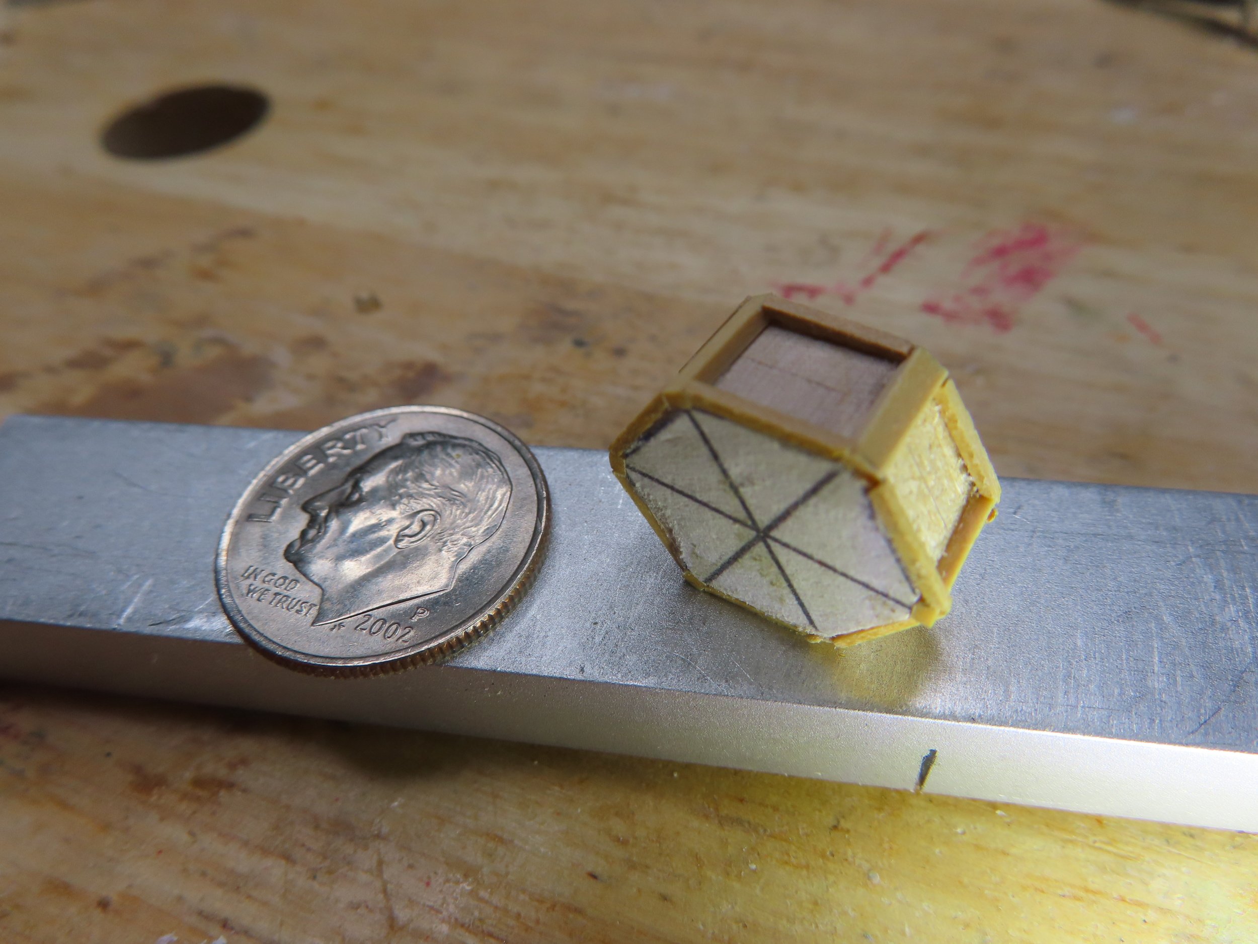
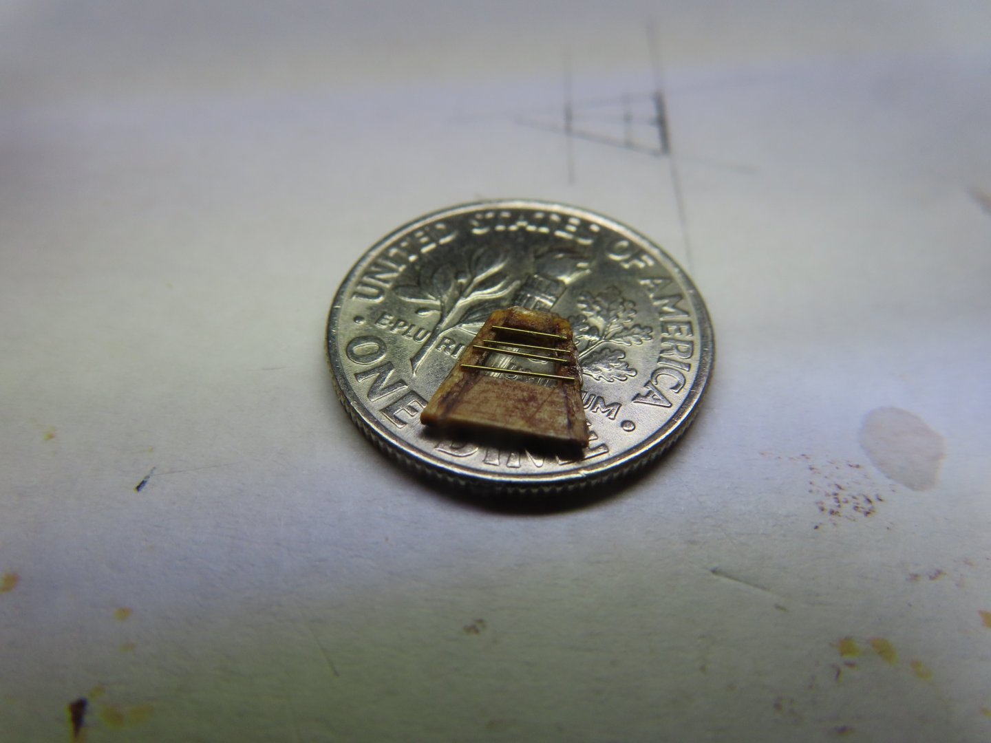
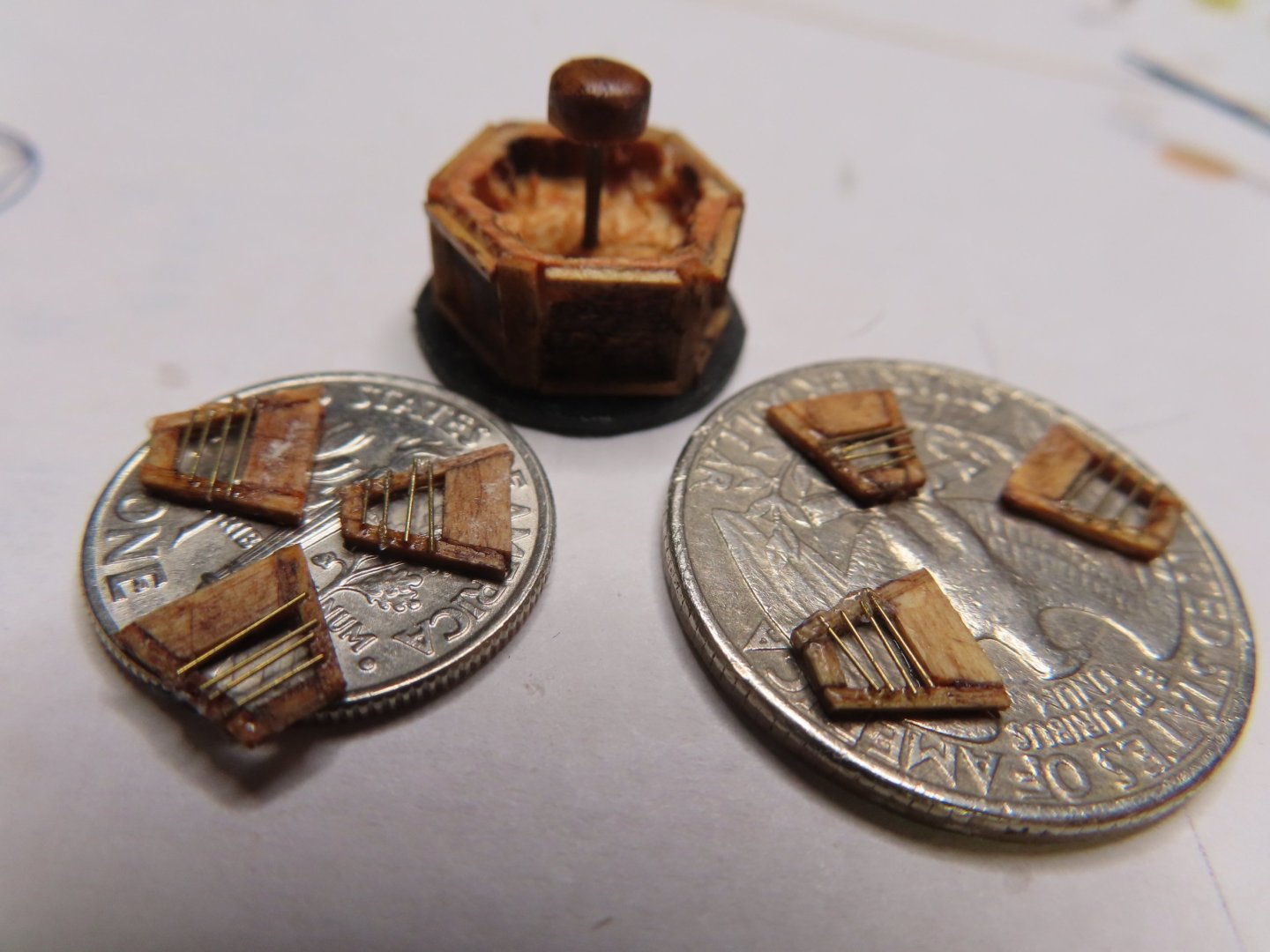
With lots of tenacity and patience, I was able to place the four wire pieces in ascending order, longest to shortest, from base to the top of the windowpane. The wires were initially held in place with a very fine drop of PVA glue at one end of each wire. This glue was used so I had time to maneuver the wire into their final positions. Once the glue set up, CA glue was used to secure the wire at their other ends. In the end, the skylight which fits on a US quarter coin, is comprised of 82 separate parts: 1 Base with six faces each base face - 4 base frame pieces x 6 f aces = 24 pieces 1 Dome support wire 1 Dome 1 base plate 6 Window panels each consisting of: 4 window frames = 24 pieces 1 piece mica = 6 pieces 4 pieces wire = 24 pieces I’m not trying to make excuses, but with 82 separate parts, those tiny precision errors add up. On this scale, my novice workmanship is showing with these closeup images. It’s something I’ll have to live with it. The skylight will put aside till it’s time for its installation. Now, back to working on the canopy frames.

-
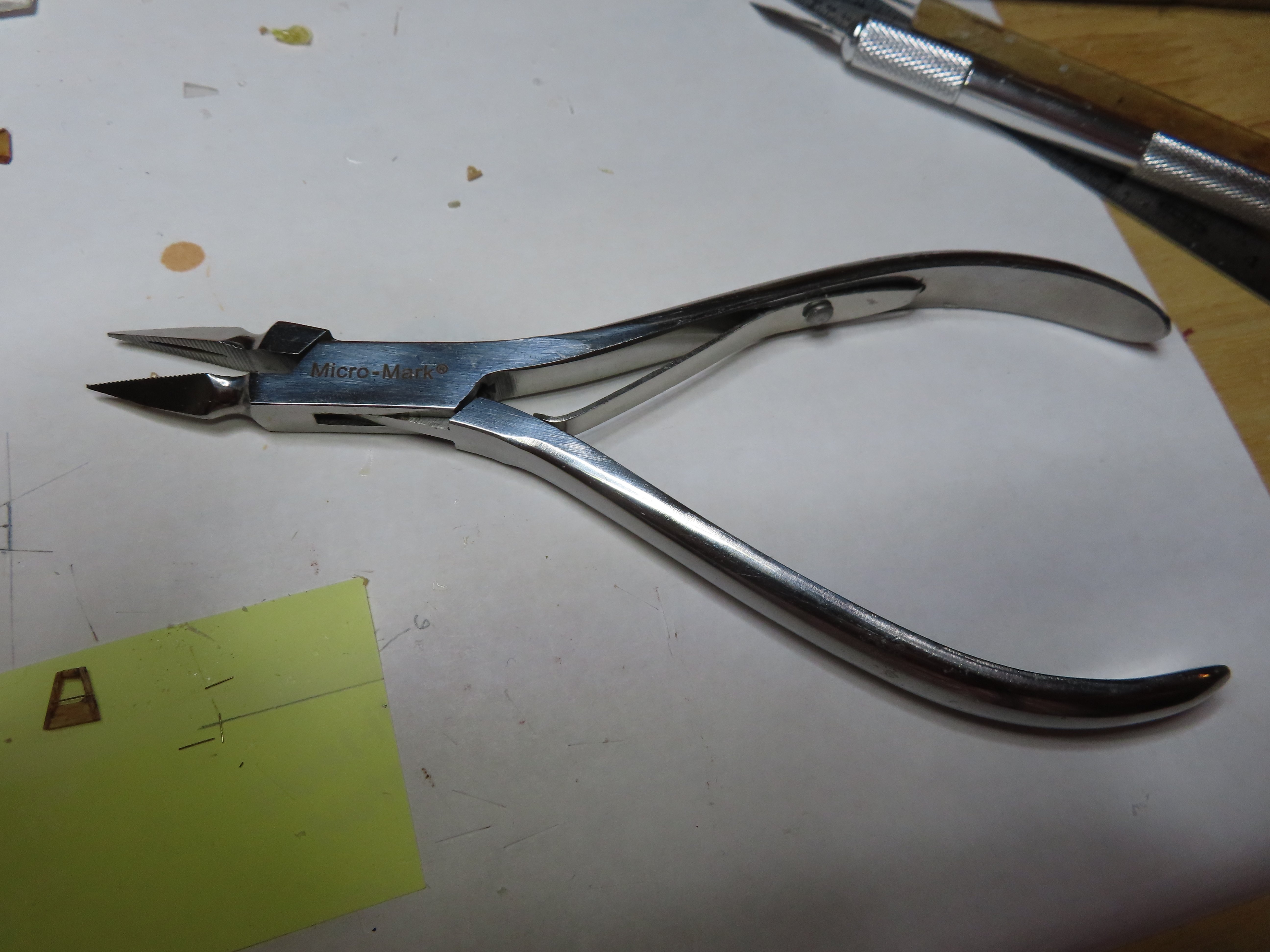
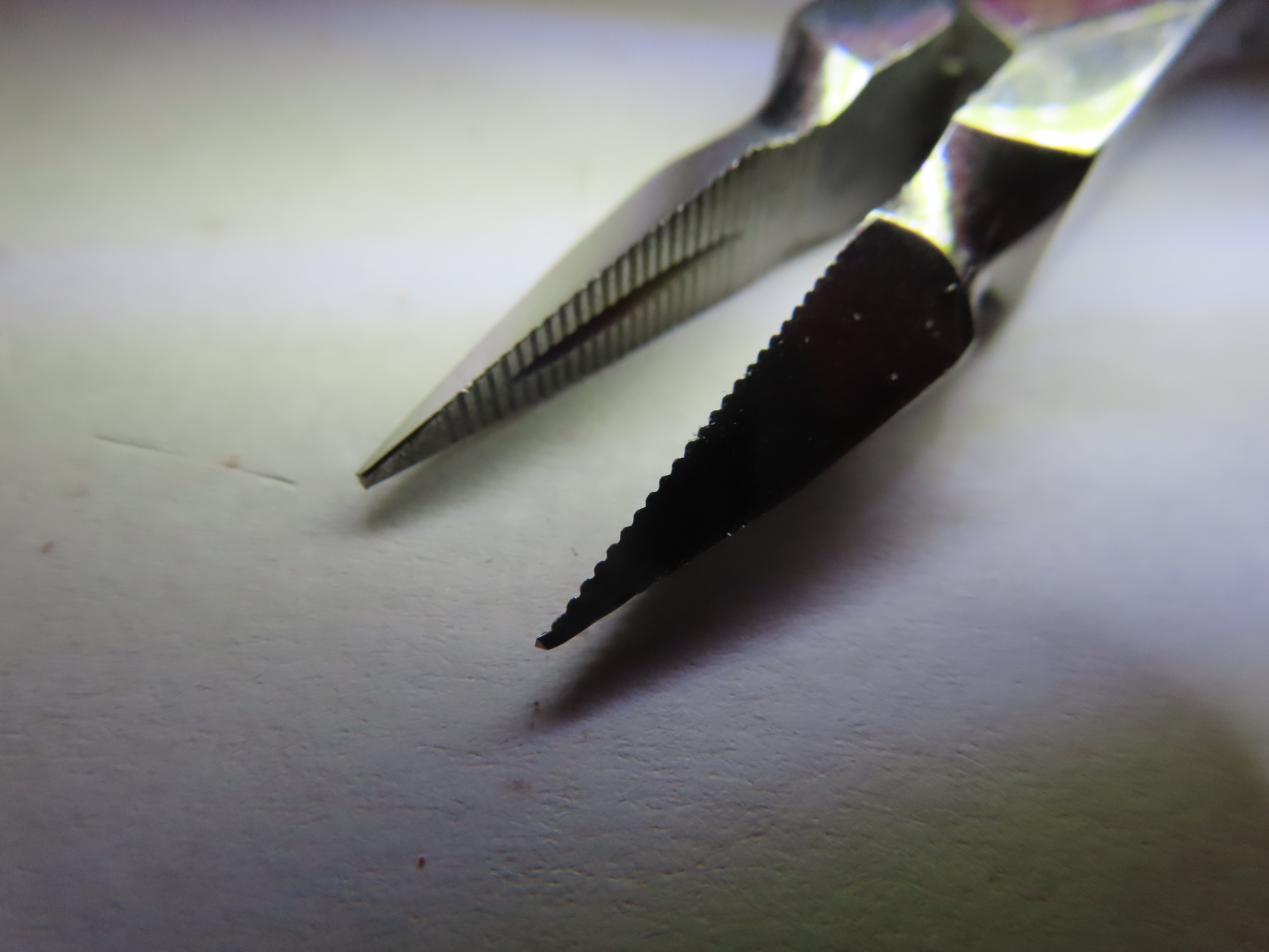
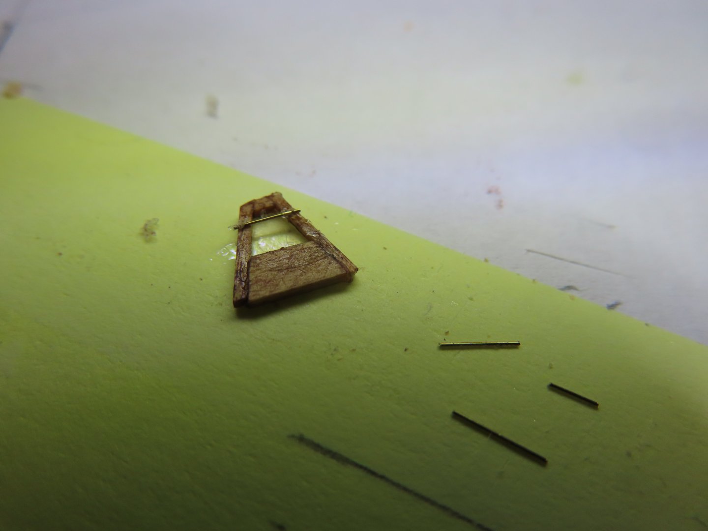
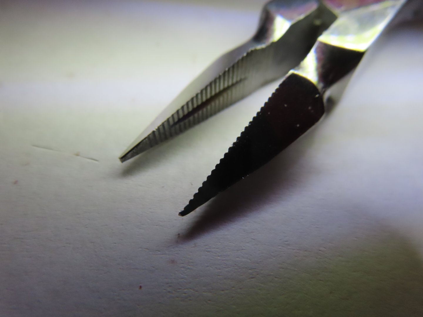
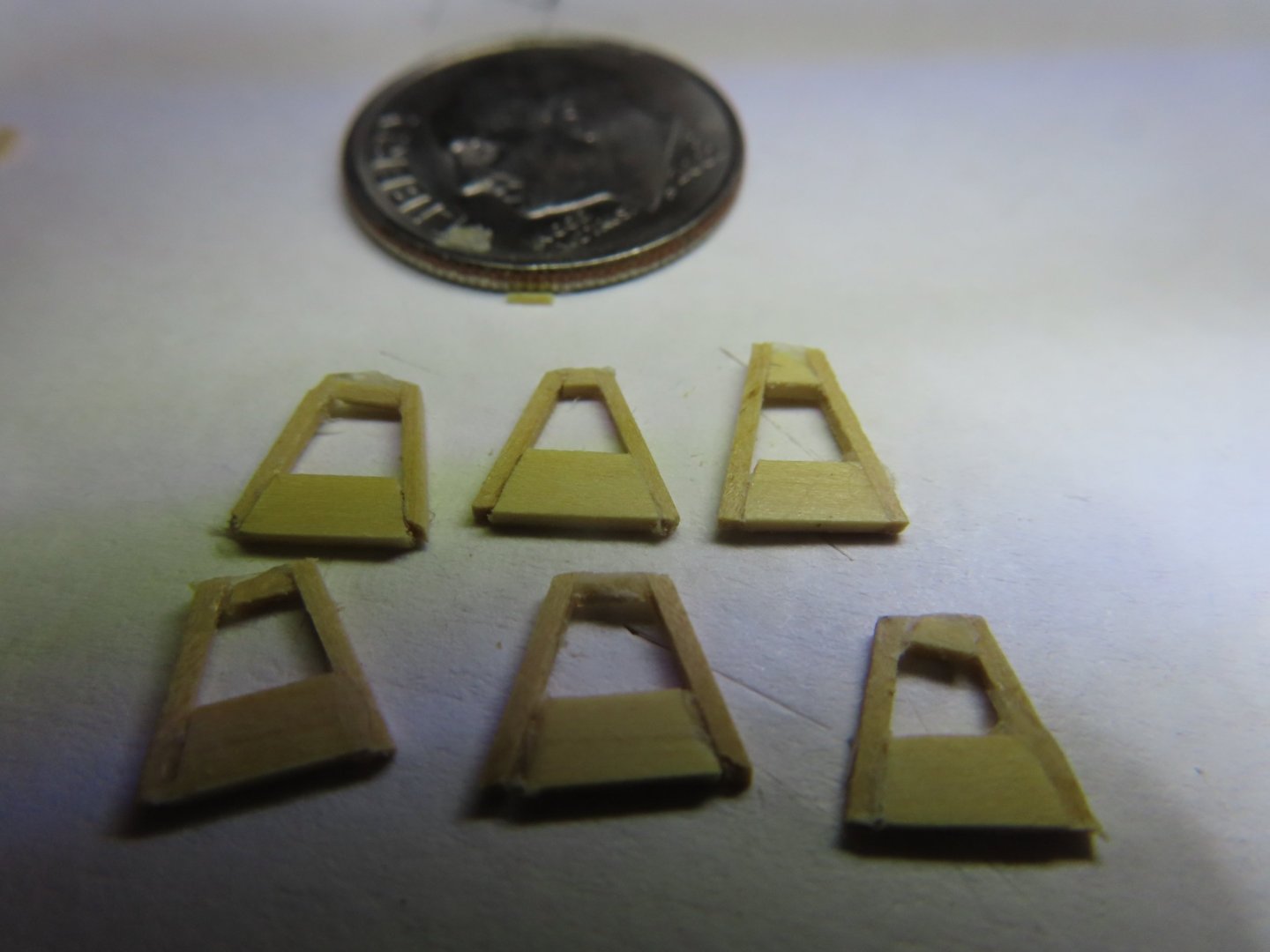
As I was about to add the Infini Model Micro Fine Brass Wire 0.1mm IBW-1000 (0.004”) wire to protect the windows, I realized that the 0.1 mm wire I ordered was not the wire I received. I got Infini Model Micro Fine Brass Wire 0.2mm IBW-2000 (0.010”). Although technically a bit oversized, as it turned out it looks better for the model and that is what counts. The four cut wire parts per panel were of four different short lengths due to the trapezoidal shape of the windowpanes. They were very thin which made it difficult to pick up. My two forceps tweezers were just about useless. Compared to the working space on the panels, the tips of the tweezers looked like tree stumps in comparison, and I couldn’t pick up the wire pieces off the workbench surface due to their rounded tips. I ended up using my rarely used sharp but relatively heavy needle-nose pliers I had bought some years back. It was a bit awkward to use, but it got the job done.

-
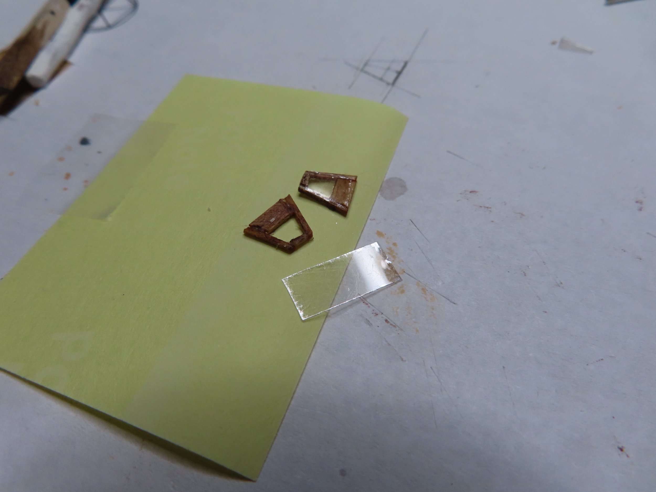
The windows panes were made from mica cut to size and fastened on the backside with CA glue. Just a fine drop was all that was needed for capillary action to suck in the glue between the wood frame and mica lying on it


-
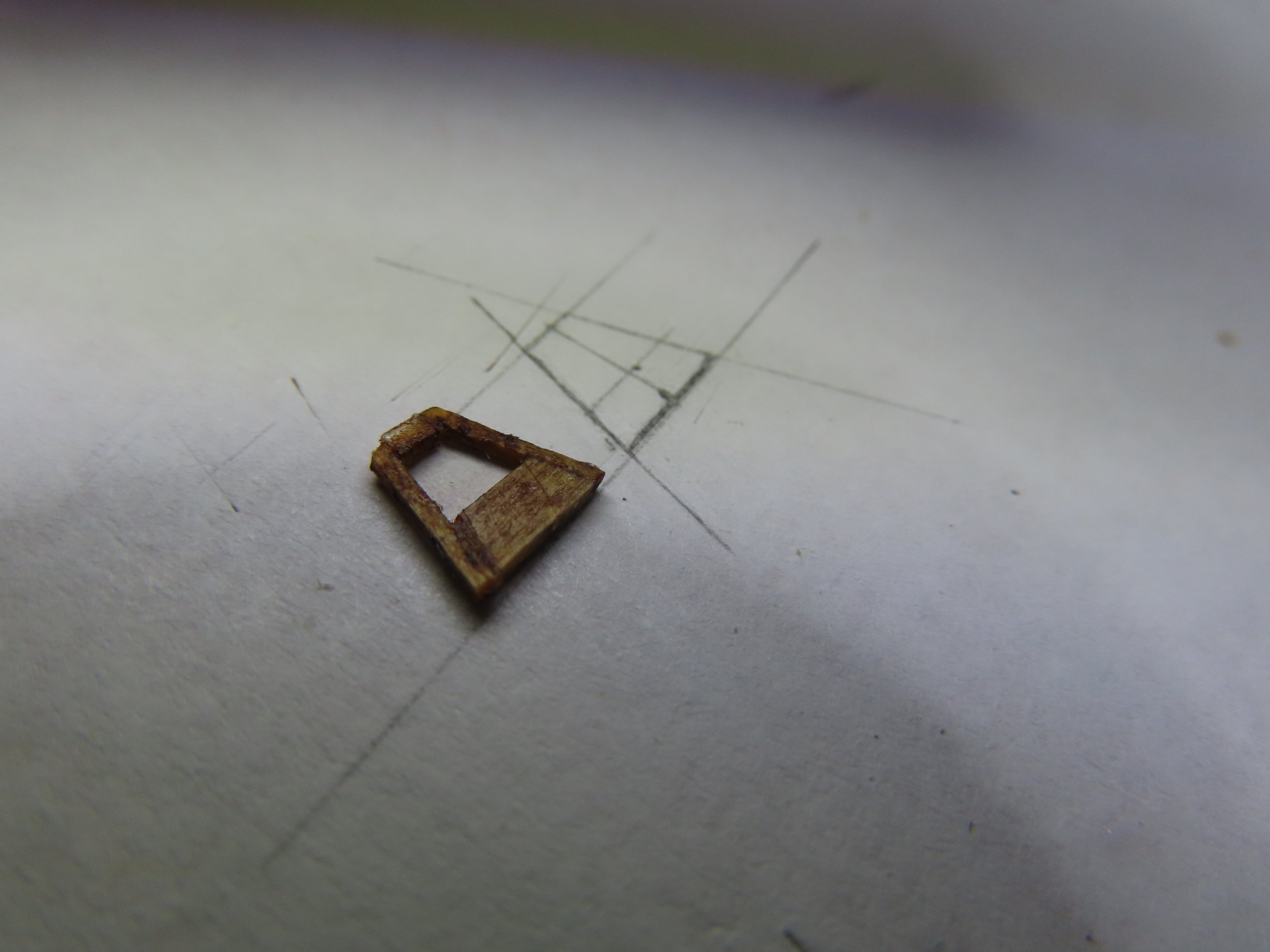
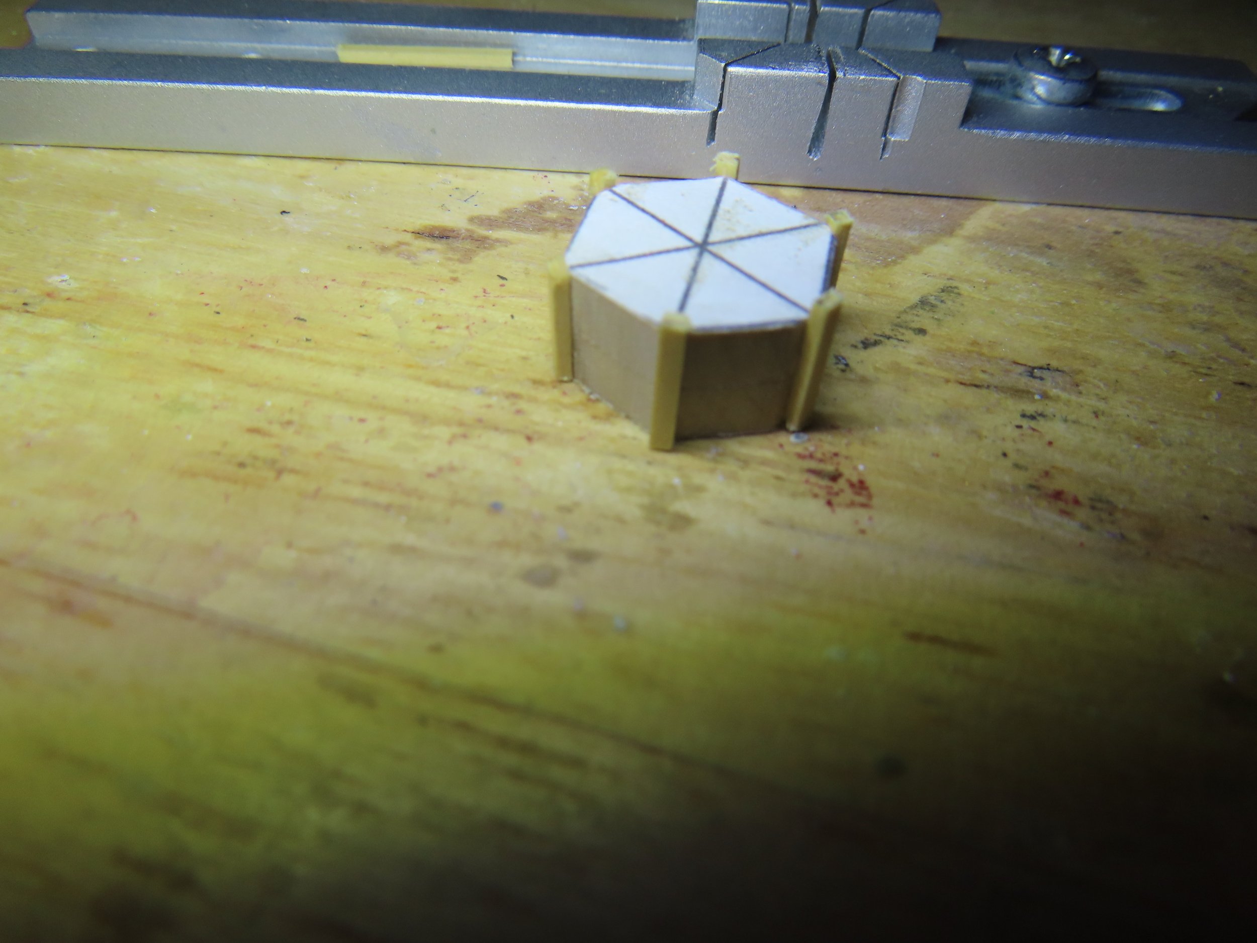
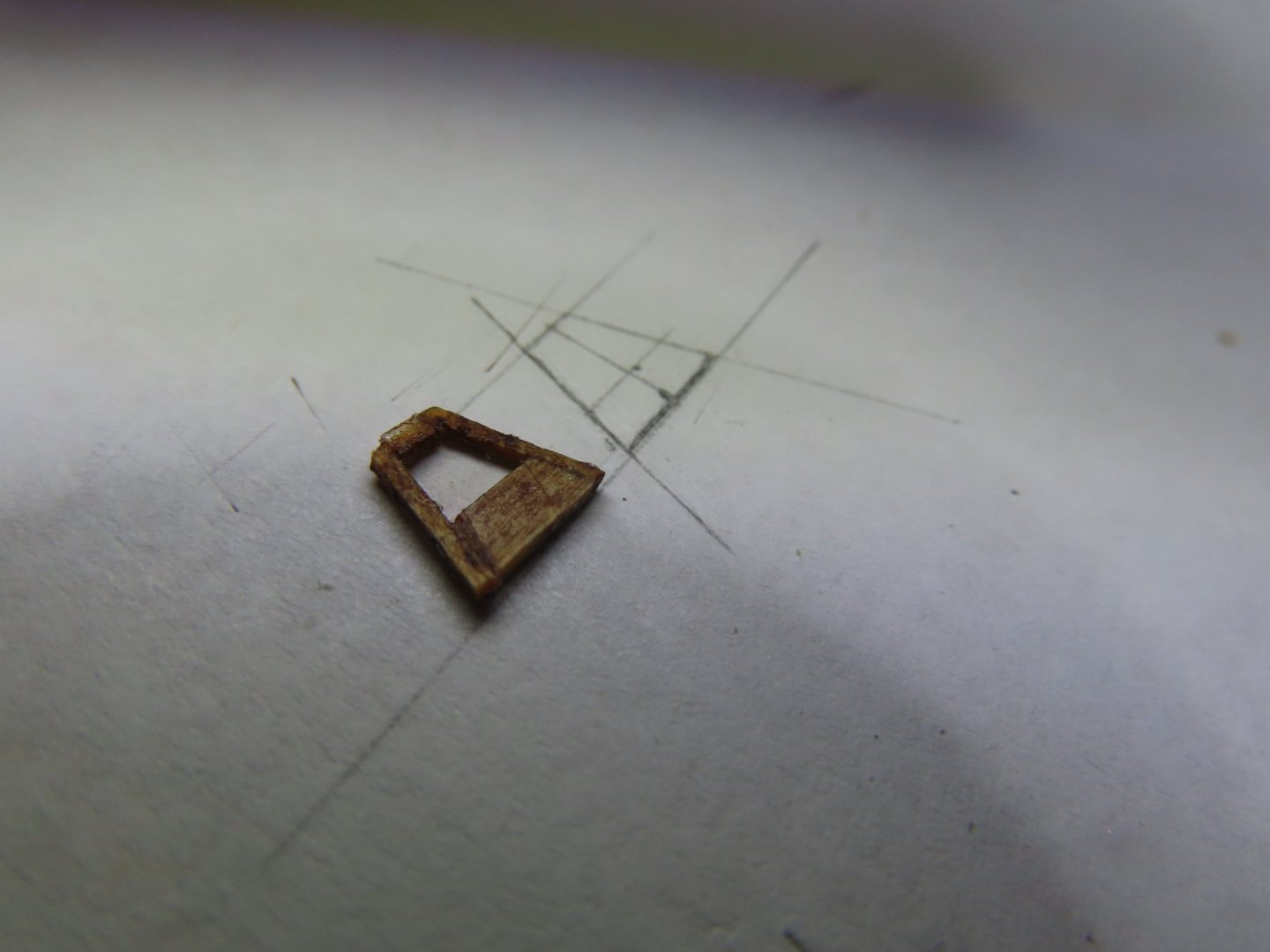
The skylight’s side and top window framing was made from 1/32” x 1/32” boxwood stock. The bottom was made from 3/32” x 1/32” stock. An outline was drawn on paper and covered with wax paper. The frames were lined up with drawing and fastened with PVA glue so the parts could be adjusted before drying.
-
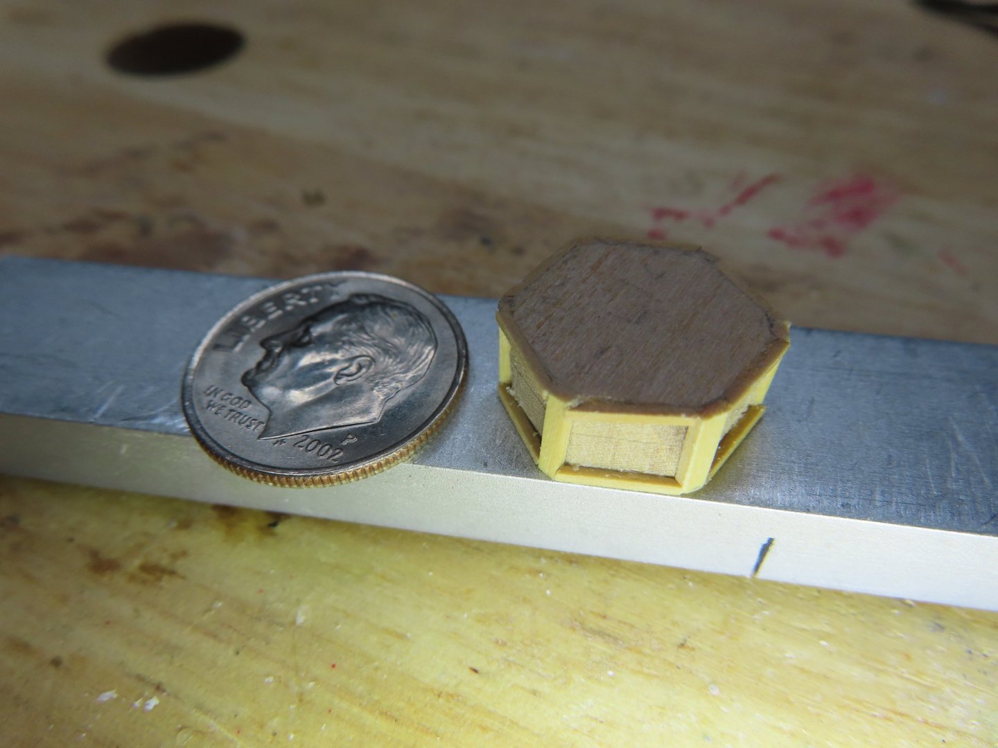
The skylight sits on a 1” thick round platform protruding about 1” wider than the skylight structure footprint. Because this component will be painted black, be mostly covered by the skylight, and I didn’t have a readily available piece of 1/32” basswood or boxwood wide enough, I used 1/32” plywood. NOTE: The practicum calls for the round platform to be painted Bulwark Green. Why, Mr. Hunt chose this color I don’t know because I could not find any images showing a green platform, just black.

-
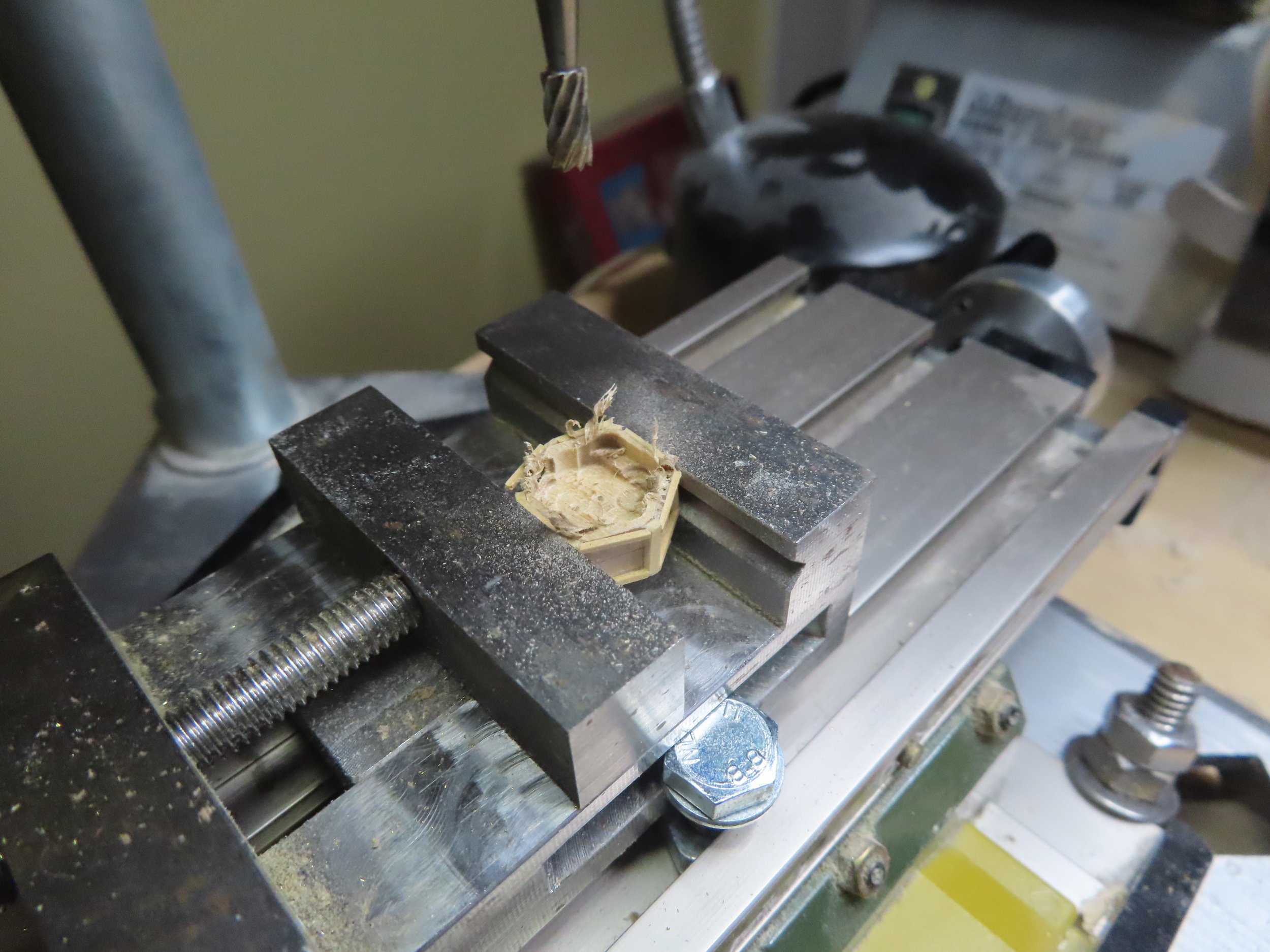
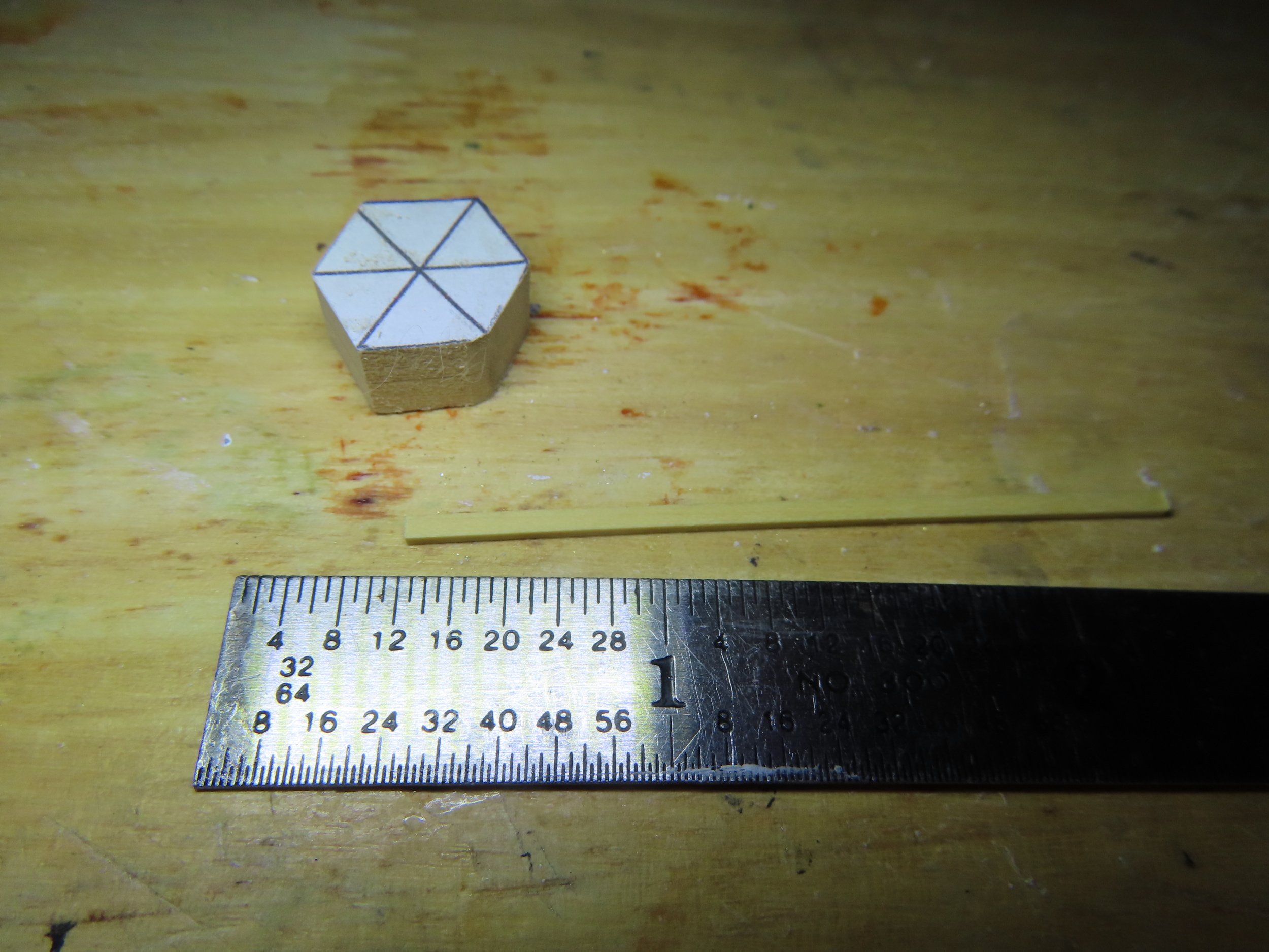
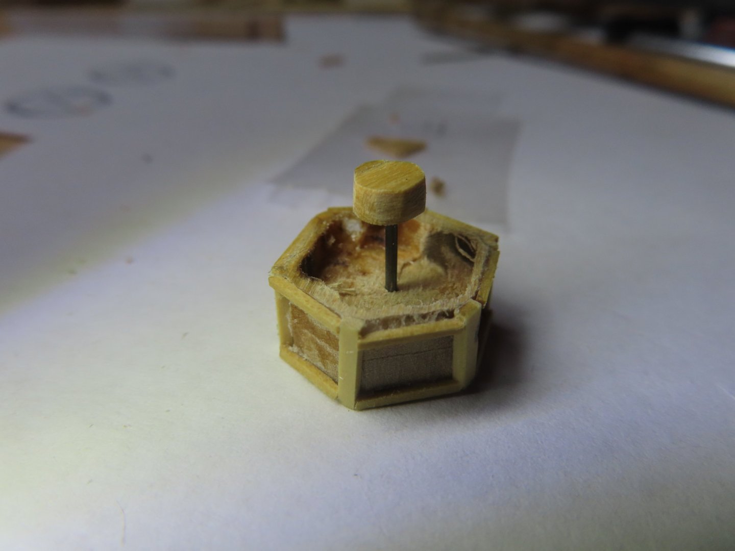
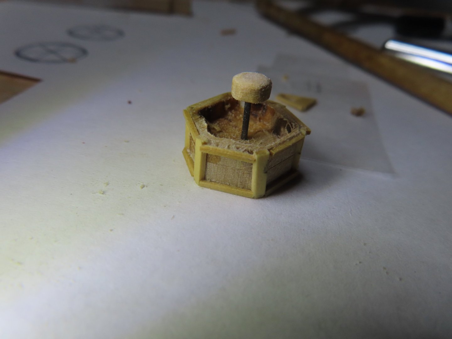
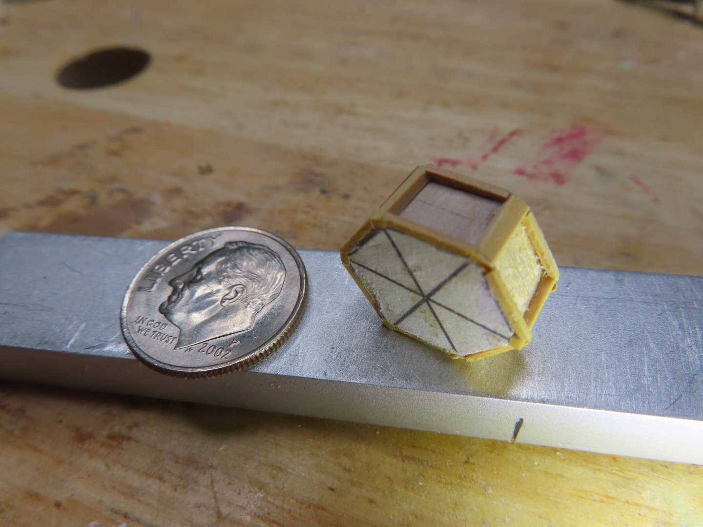
Then, the wire and dome were removed, and the base was hollowed out halfway down. This was done to create the illusion the base was totally hollow. The top piece was rounded off to create the roundness of the dome. Now, when the base, wire, and dome were assembled, I had a solid structure to support the windows. According to the US Navy plans, the dome was made from mahogany. No mention what type of wood the rest of the structure was made from, so I assumed it was the same. However, the photo images seem to show the skylight was the same color as most of the wood on the spar deck which was not mahogany. The mahogany stain I had gave a deep reddish tone, almost black looking which I didn’t want. Therefore, I initially stained the wood with Miniwax Gunstock, then applied a light coat of Miniwax Red Mahogany.

-
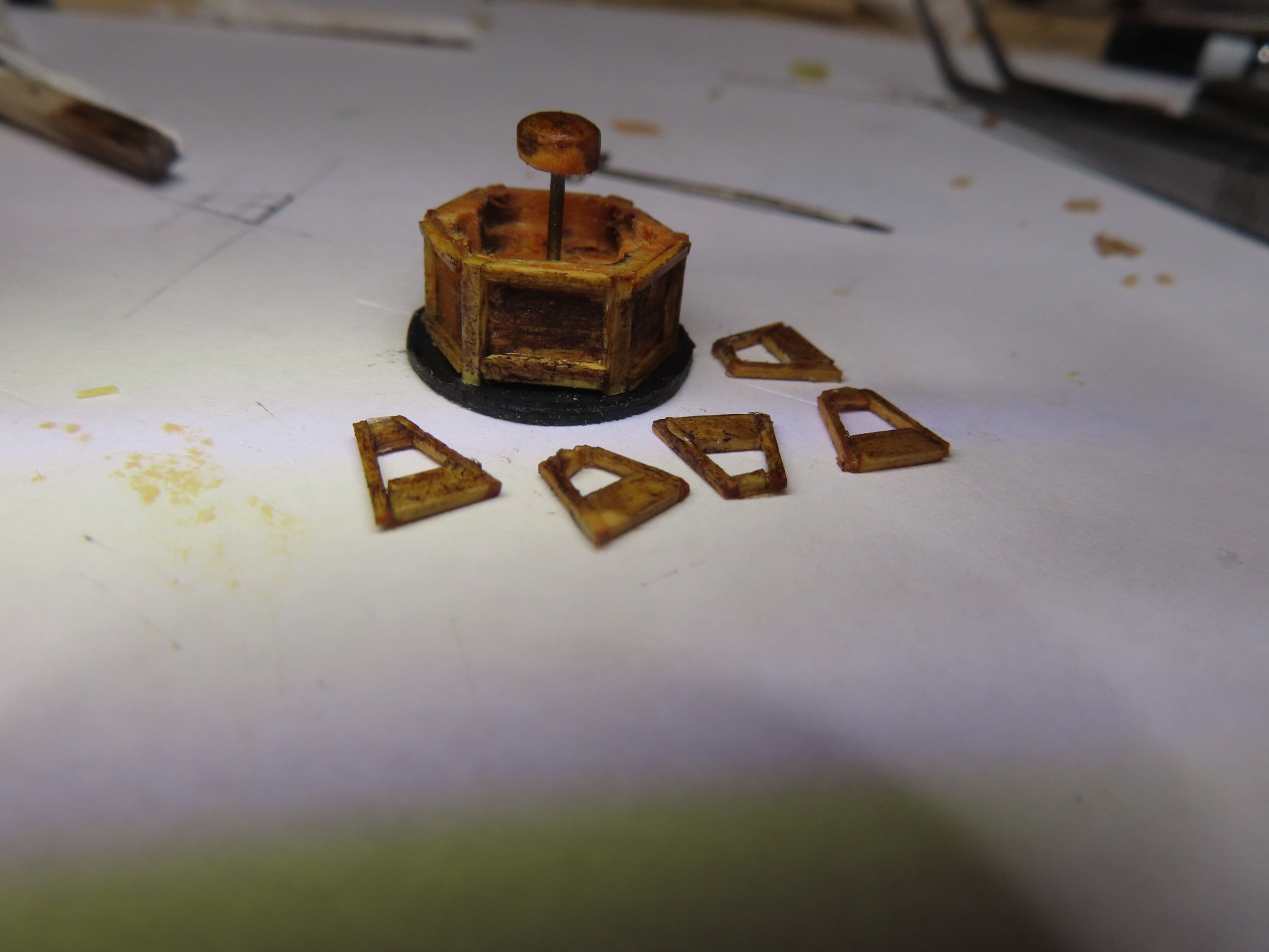
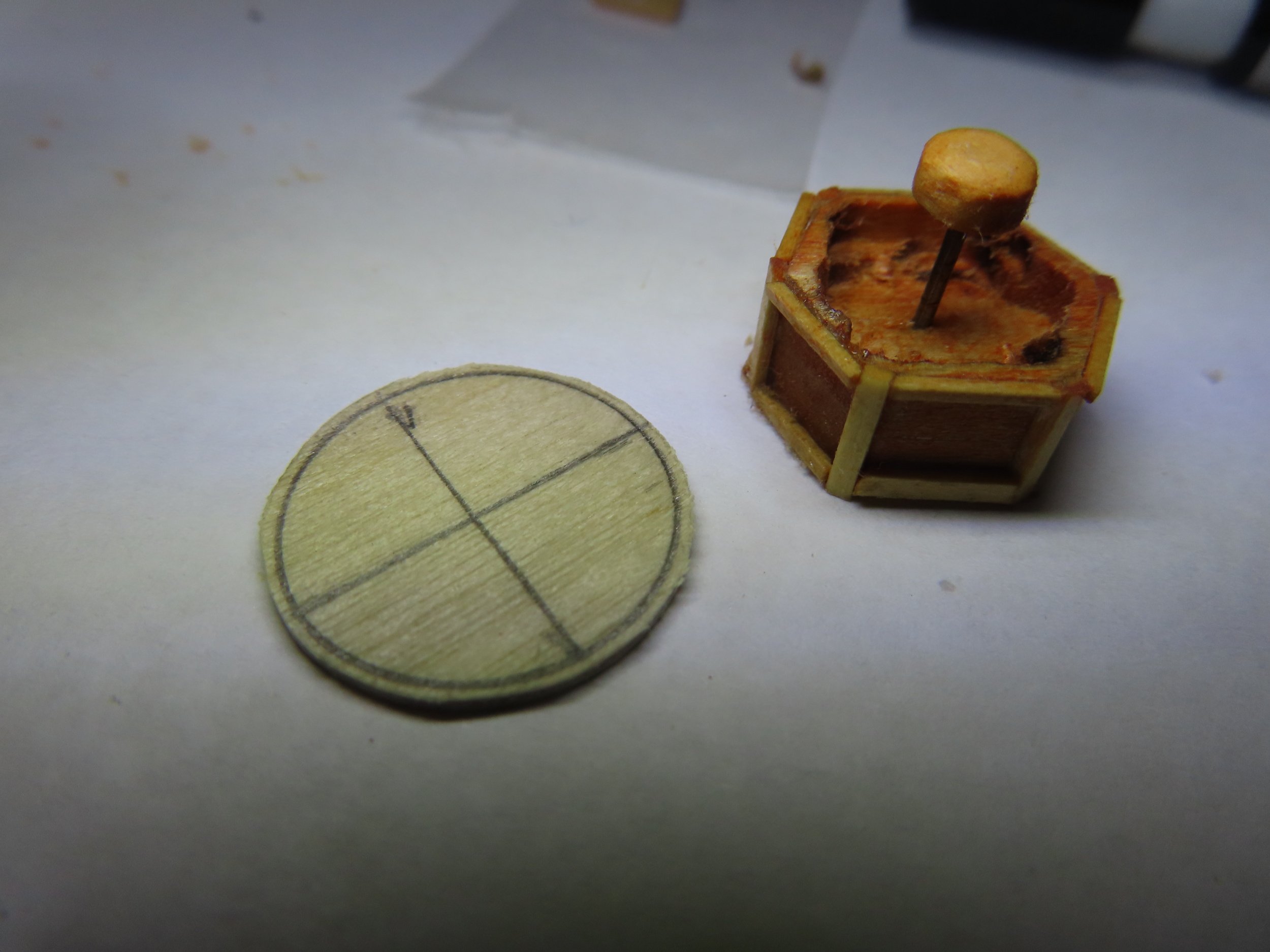
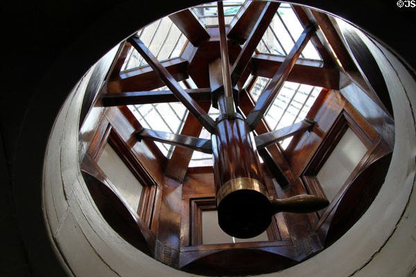
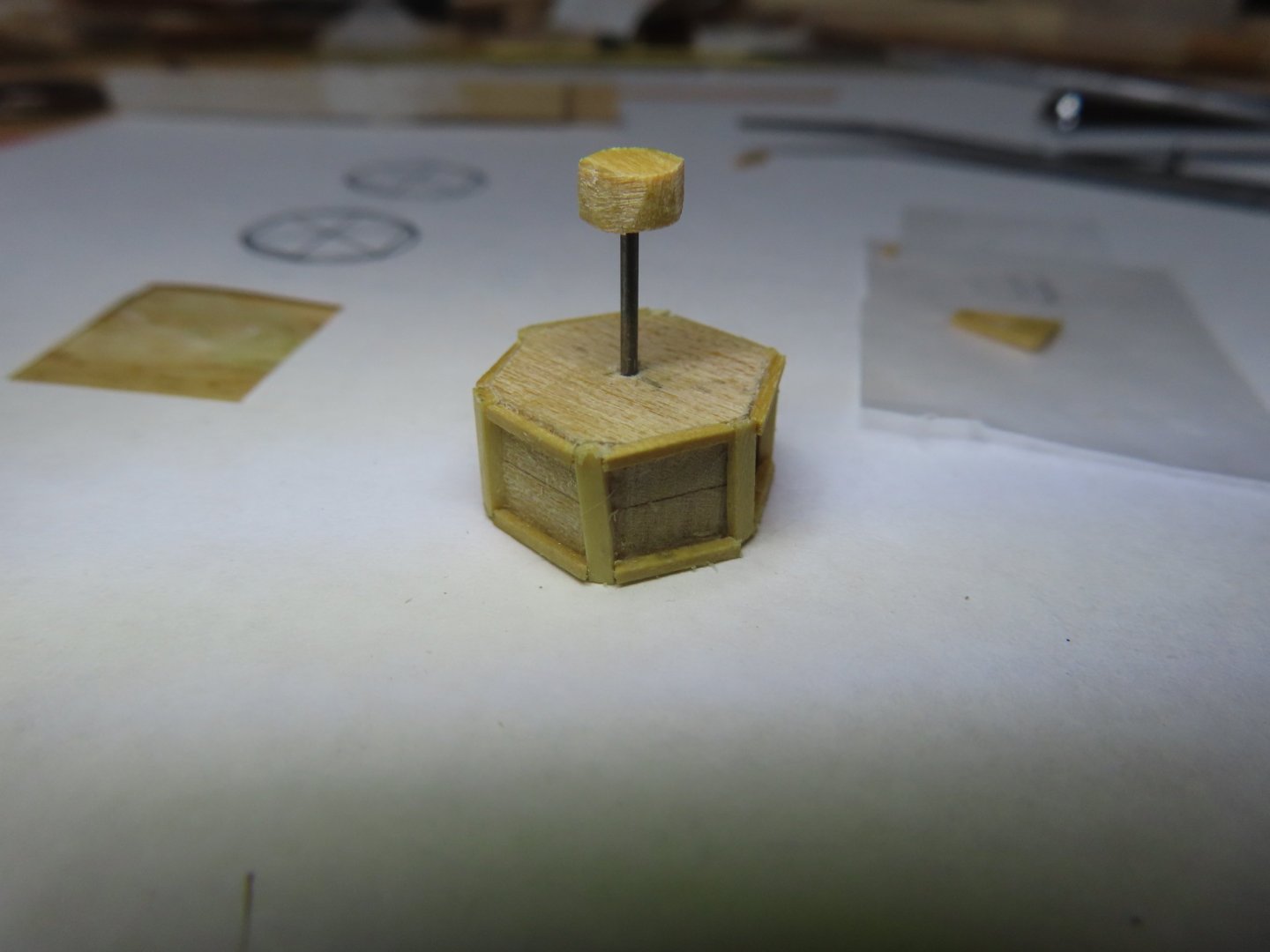
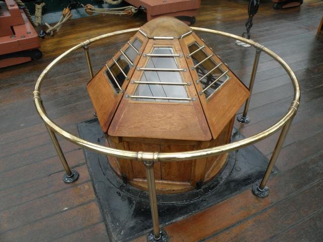
The skylight windows invited numerous methods from a variety of builders depending on whether the skylight was solid wood mimicking a glass enclosure or an actual framework. My method is also a bit unique. Because I intended to make actual windows with a frame and glass (mica), the window frame would only be supported at the base and top of the window frame. Therefore, I had to create a “floating” top support. The actual skylight has a wood dome with an internal mechanism to facilitate the opening and closing of the windows. So, that inspired me to have my dome supported by a pole paying homage to the real thing. An extended dome was fabricated out of boxwood with a hole drilled about halfway through to accept a piece of music wire. Another hole was drilled through the base to support the wire. The dome was stuck on the wire, inserted into the base, tweaked so that the top of the dome was ½” from the bottom of the base.


-
The side border framework was made from 1/16” x 1/32” boxwood.


-
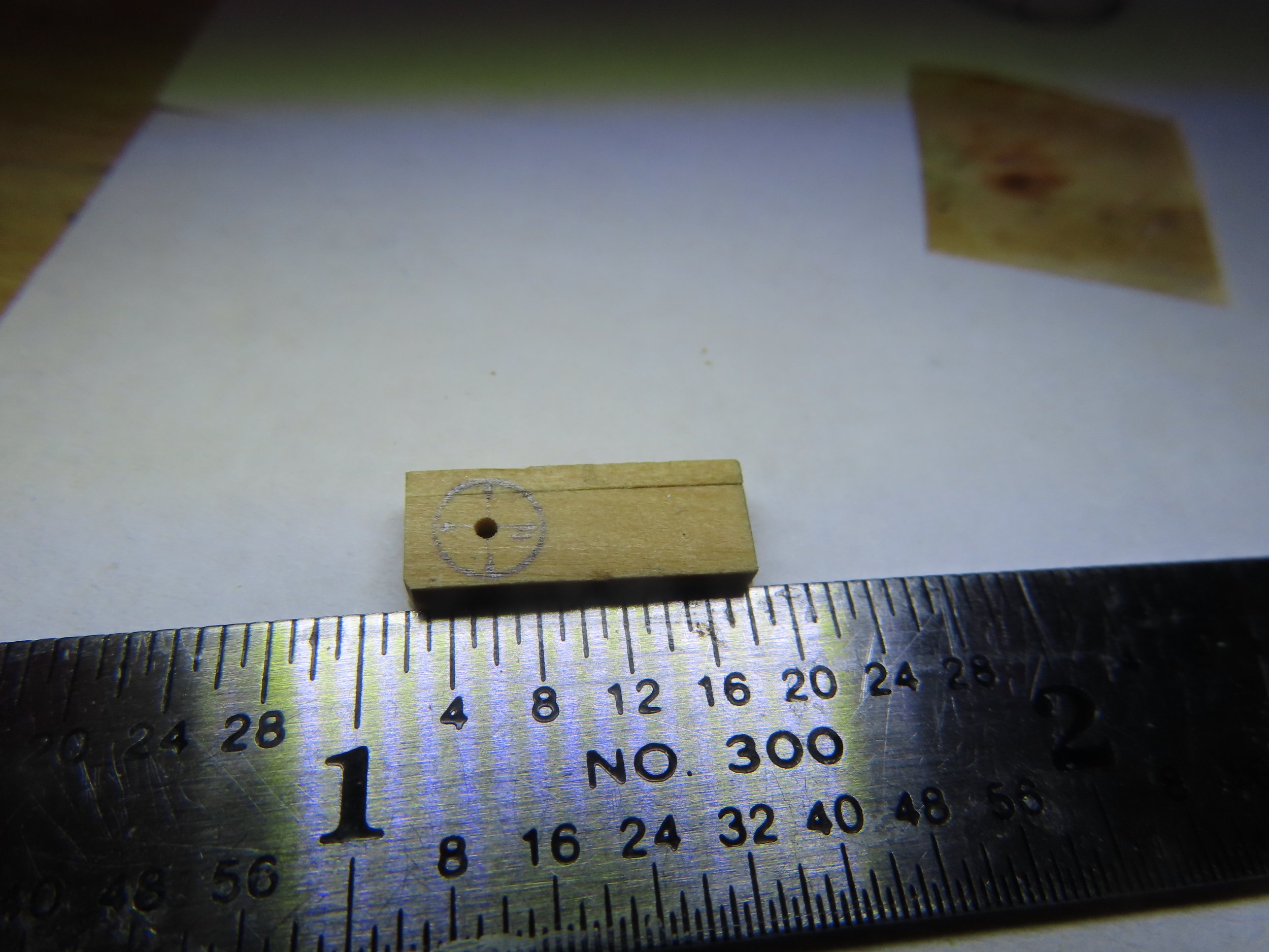
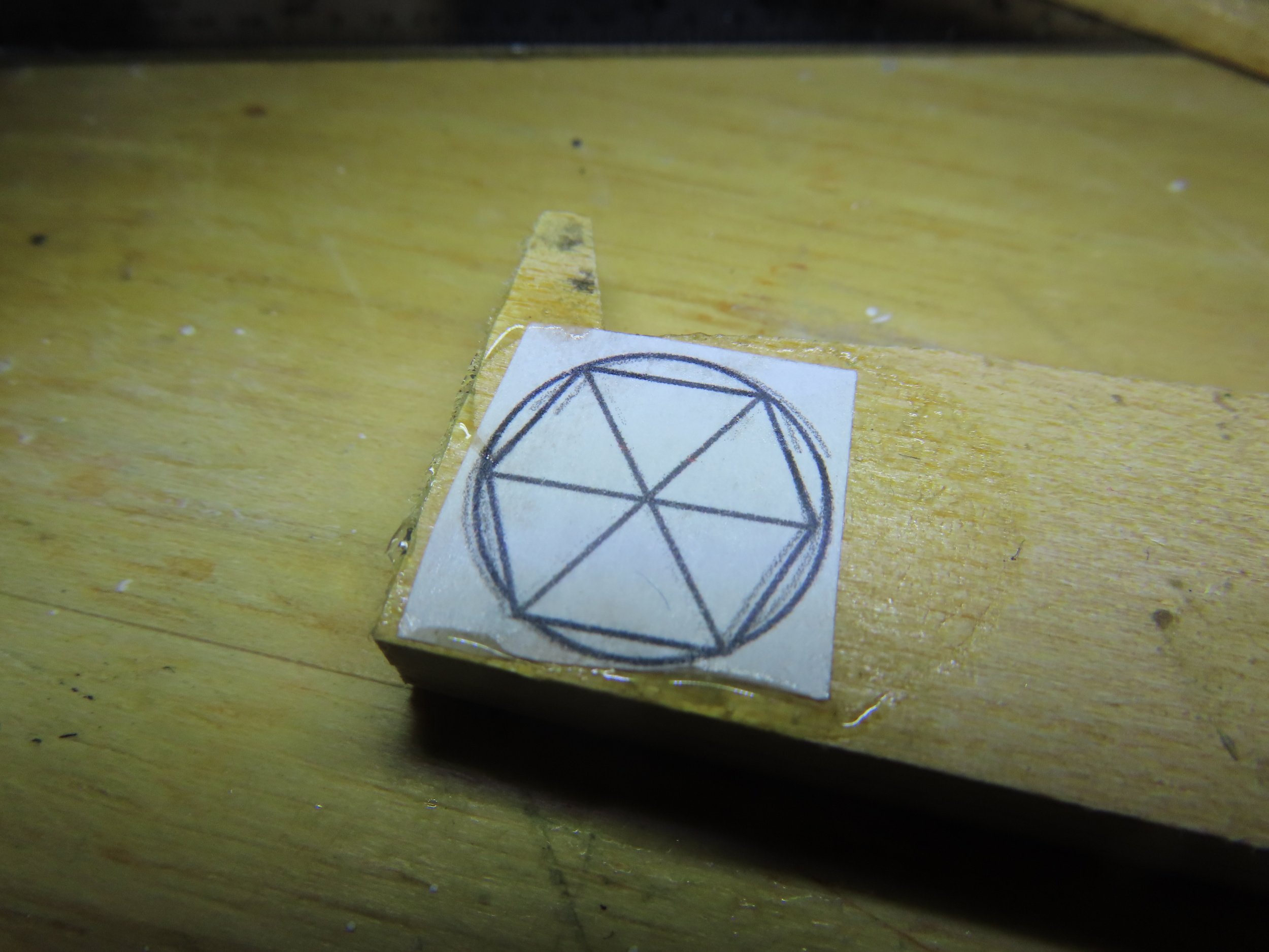
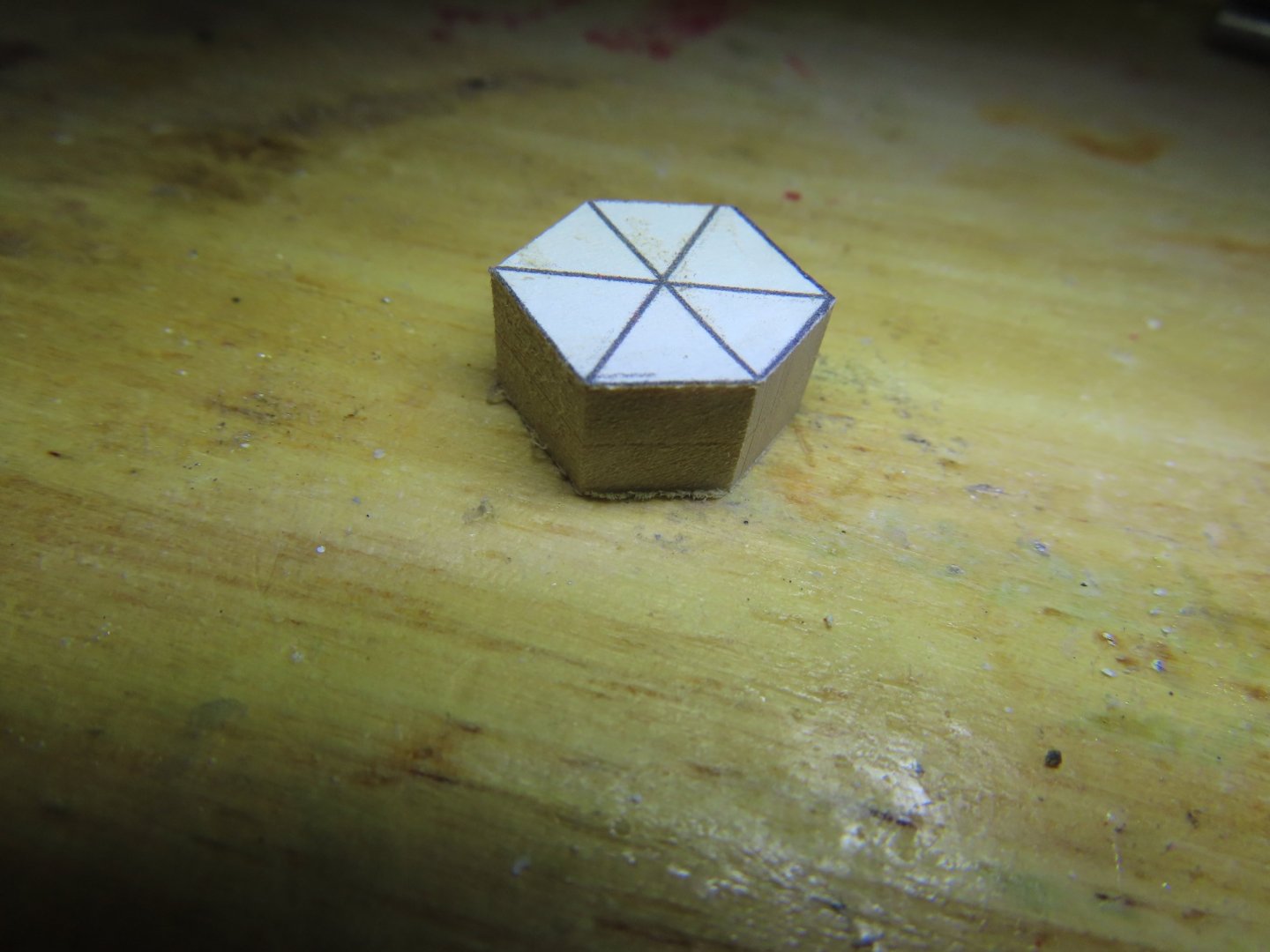
As usual, the first thing I did was gather my materials needed for this endeavor. One of the items was brass wire for the horizontal 3/8” brass bars protecting the glass windows. This scaled down to 0.005” or 36-gauge brass wire which Mr. Hunt did use on his construct. However, try as I might, I could not locate 36-gauge identified brass wire to purchase. I did find Infini Model Micro Fine Brass Wire 0.1mm IBW-1000 (0.004”) online at A-Z Toy Hobby in Texas. I don’t think anyone will notice the 0.001” difference in thickness. Using the template from the practicum, the skylight base core was cut from ¼” thick basswood stock.

-
While I waited for the new drill bits to arrive, I put the canopy stanchions on hold and started to work on the captain’s skylight. This took longer than I had expected, and the time was also interrupted with my annual Thanksgiving weeklong trip to my sister’s home where the family gathers for the holiday. I studied the practicum method, xKen’s method and others. Since I am a glutton for punishment, I chose not to take the simple route. I wanted transparent windowpanes and close to scale details which meant, I would be using Ken Foreman’s as a guide more than Bob Hunt’s. Also, Bob did not fabricate the brass railing surrounding the skylight which Ken did.
-
The photo of the anchor was taken May 5,1931 by Leslie Jones. I have six more similar images taken at the same time should you want them. Jon
-
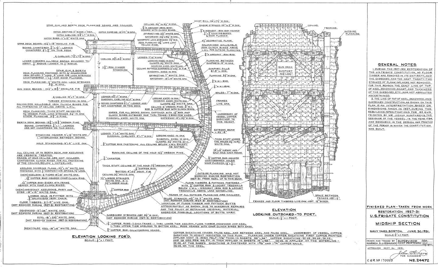
I didn't find any additional detail on the waterways other than this 1927 version of the midsection section which just states "solid waterways" & "white oak," with a clear image of the waterways cross section. As for the joints, they are probably some sort of lap joints. but any detail would be perpendicular joint lines and those be barely visible on bare wood. Your model would get the same visual effect from a simple butt joint. I think any effort to make them more prominent, would render them out of scale and not help the model. Jon

- 233 replies
-
- 2
-

-
- Model Shipways
- constitution
- (and 5 more)
-
Click here for unegawaya One of the reasons the waterway is installed first is because that's the way the actual ship was built (see cross section plan). I see no reason you couldn't plank first then add the waterways second for a model. You would have to modify the waterway cross section to account for the planking under it. Jon
- 233 replies
-
- 3
-
-
- Model Shipways
- constitution
- (and 5 more)
-
USS Constitution by mtbediz - 1:76
JSGerson replied to mtbediz's topic in - Build logs for subjects built 1751 - 1800
Just catching up on a week's worth of everyone I've following's build logs. Beautiful work as always. Jon -
USS Constitution by mtbediz - 1:76
JSGerson replied to mtbediz's topic in - Build logs for subjects built 1751 - 1800
We are making models, not miniature reconstructions. I didn't cut the waterways either. It just has to look right no mater how you do it....and you do it very well. Jon -
USS Constitution by mtbediz - 1:76
JSGerson replied to mtbediz's topic in - Build logs for subjects built 1751 - 1800
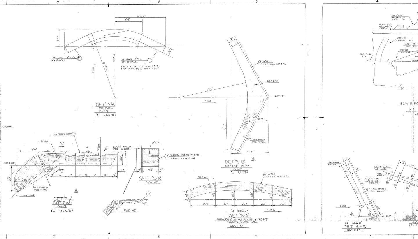
Well, I got home late Monday afternoon and saw that you completed(?) fabricating the catheads, but as promised here are the US Navy plans. Jon

-
Gregg, We are here to answer your questions as best as we can. Look forward to your build. Jon
-
I have 1 or 2 books from that era, but I'll to wait till I get home next week to check to see if I have that one. Jon
-
USS Constitution by mtbediz - 1:76
JSGerson replied to mtbediz's topic in - Build logs for subjects built 1751 - 1800
If you are willing to wait a week, I would tell you the exact US Navy plan for the catheads. I am visiting my sister for the Thanksgiving holiday and am not able to access my computer. I am using hers to communicate. Jon -
The short answer is yes, you must sign up, but it doesn't cost anything. You can also choose the language you wish to read it in. I did, and have had no problems. Jon
- 233 replies
-
- 2
-

-
-
- Model Shipways
- constitution
- (and 5 more)
-
I like Marcus' idea. You may end up with a very unique model. I have not seen any 1804 based models. This is most important. NOW is the time to make these decisions. Trying to make or change your choices after you start building up the ship's frame will become increasingly difficult. Take a look at the history of the figurehead/billethead here: https://ussconstitutionmuseum.org/2017/03/03/bow-decor/ BTW, the missing Hercules figurehead was finally replaced in 1833 with the President Andrew Jackson figurehead, an unpopular President in the Constitution's home port of Boston, Massachusetts. One stormy night in1834, a protesting local captain sawed off the wooden Jackson's head. Since then, there hasn't been a figurehead on the ship, just the billethead decoration. Jon
- 233 replies
-
- 2
-
-
- Model Shipways
- constitution
- (and 5 more)
-
The stem that came with the kit was never meant to be seen without a covering of copper plate and paint so Model Shipways wasn't concerned about the individual pieces that it was comprised of. As such, the silhouette of the stem reflects closely what the ship looks like today so I am not surprised it doesn't match the old plans. You are trying to envision the ship as she was commissioned which nobody really knows what that looked like, other than some historically based educated guesses. Your stem plan looks plausible, but probably not historically accurate. I don't have any drawings of the stem earlier than 1927. Plan 14705 shows what the stem looked like prior to the 1927-31 restoration. So, if you were to try to me be more historically accurate, I would try to make the stem look more like what the 1927 plans show. Here are the plan numbers I have. If you can't find all of them at the museum, let me know. Here is the earliest know photograph of the ship showing her stem during her restoration in Portsmouth, Maine 1858. 1927 - No.: 14705 1927 - No.: 25006 1927 - No.: 25026 1929 - No.: 24779 1972 - No.: 25007 Hope this helps, Jon

- 233 replies
-
- 1
-

-
- Model Shipways
- constitution
- (and 5 more)
-
I would take the drawing you made in your last post, copy it and copy again in mirror image (port and starboard). Make a template by cutting the whole image as a whole out of the paper and with rubber cement, glue it to the stem on the model. With a sharp blade or using pin points, imprint the "puzzle pieces" into the wood. Then you can peel off the templates and finish embossing the lines into the wood. Jon
- 233 replies
-
- 3
-
-
- Model Shipways
- constitution
- (and 5 more)
-
If the ship didn't already have a name, I would have suggested you name her Tenacity, because that's what it took to get the model to this stage! Jon