JSGerson
-
Posts
2,633 -
Joined
-
Last visited
Content Type
Profiles
Forums
Gallery
Events
Everything posted by JSGerson
-

USS Constitution by mtbediz - 1:76
JSGerson replied to mtbediz's topic in - Build logs for subjects built 1751 - 1800
It will be interesting to see how you fabricate the curved bow waterways. Jon -
Well you went from "damn near perfect" to perfect. Well done!! Jon
-
USS Constitution by mtbediz - 1:76
JSGerson replied to mtbediz's topic in - Build logs for subjects built 1751 - 1800
As expected: neat, clean, and well executed! Jon -
I'm getting my materials and tools together preparing to start drilling brass blocks. Based on your comments about drilling speed, I'll switch to my variable speed Dremel in order to get the slower drilling speed. I also may have some cheap drill bits, which didn't make too much of a difference when used on wood. In the past, when applying a little drill pressure, some of my bits have bent. I can understand if a small diameter bit snaps, but to me, bending means that the metal wasn't tempered properly to make it stiff for a straight cut. It would also mean the drill tip can't hold an edge. Thanks for your insight. Jon
-
That's damn near perfect. Just add your transparent material to the black backing prior to the frame work to get that pane glass look. I admire your tenacity. Jon
-
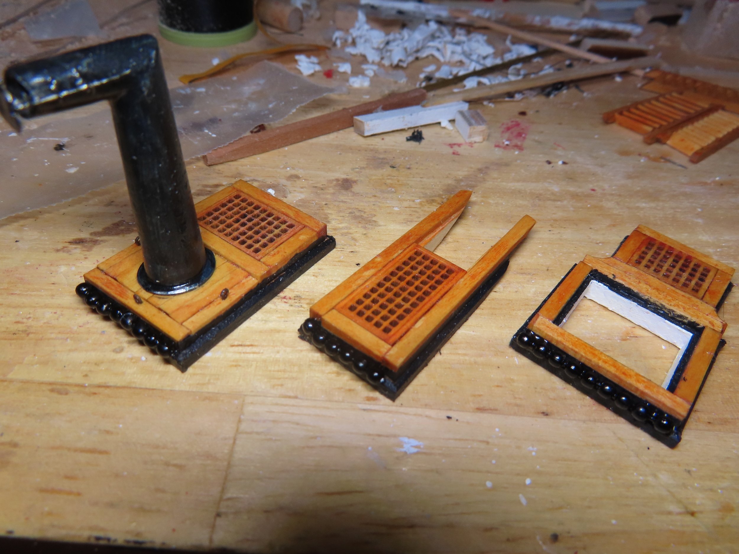
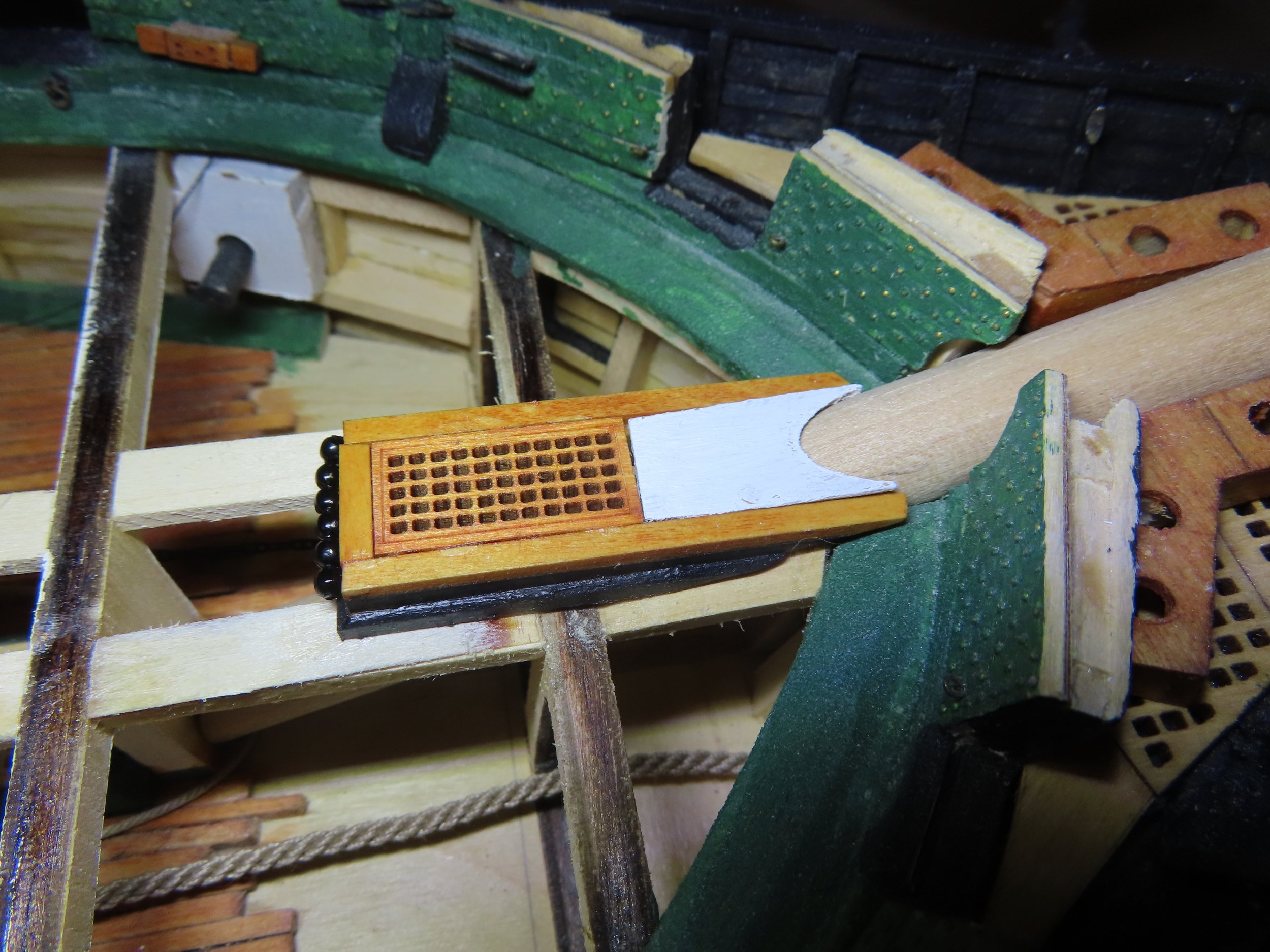
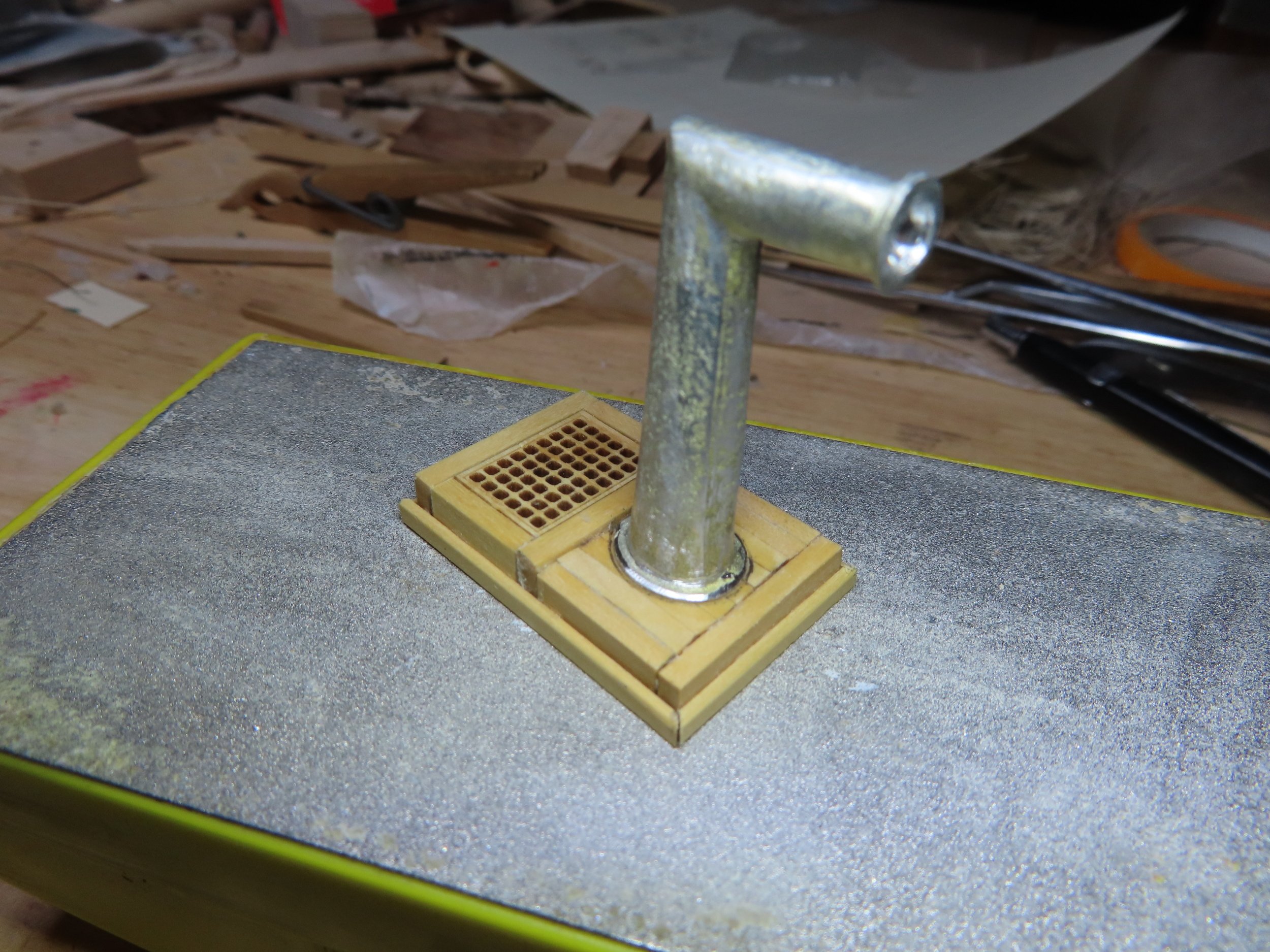
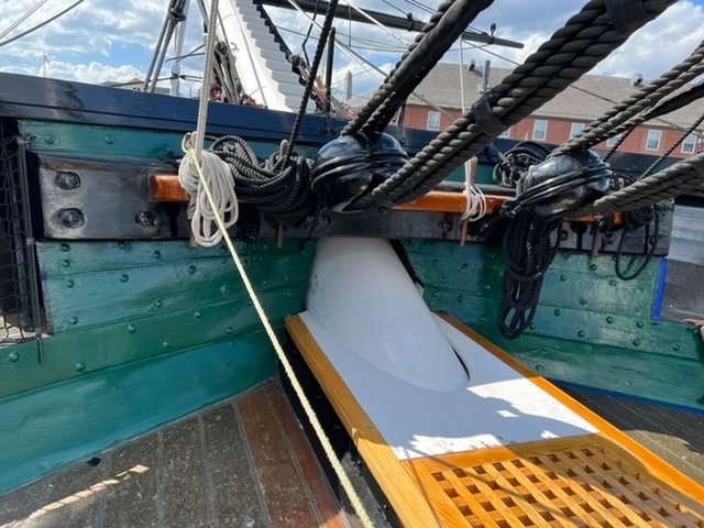
The bowsprit hatch was completed by carving the forward insert around the dowel that would eventually become bowsprit. It was then painted white and dry fitted into place. The unit was then glued to the deck. The dry fitting was necessary so the insert can be removed to allow the dowel to be fitted into the model as it is fabricated and adjusted to its final configuration. Once the bowsprit is secured into place, the insert will be glued in as well.


-
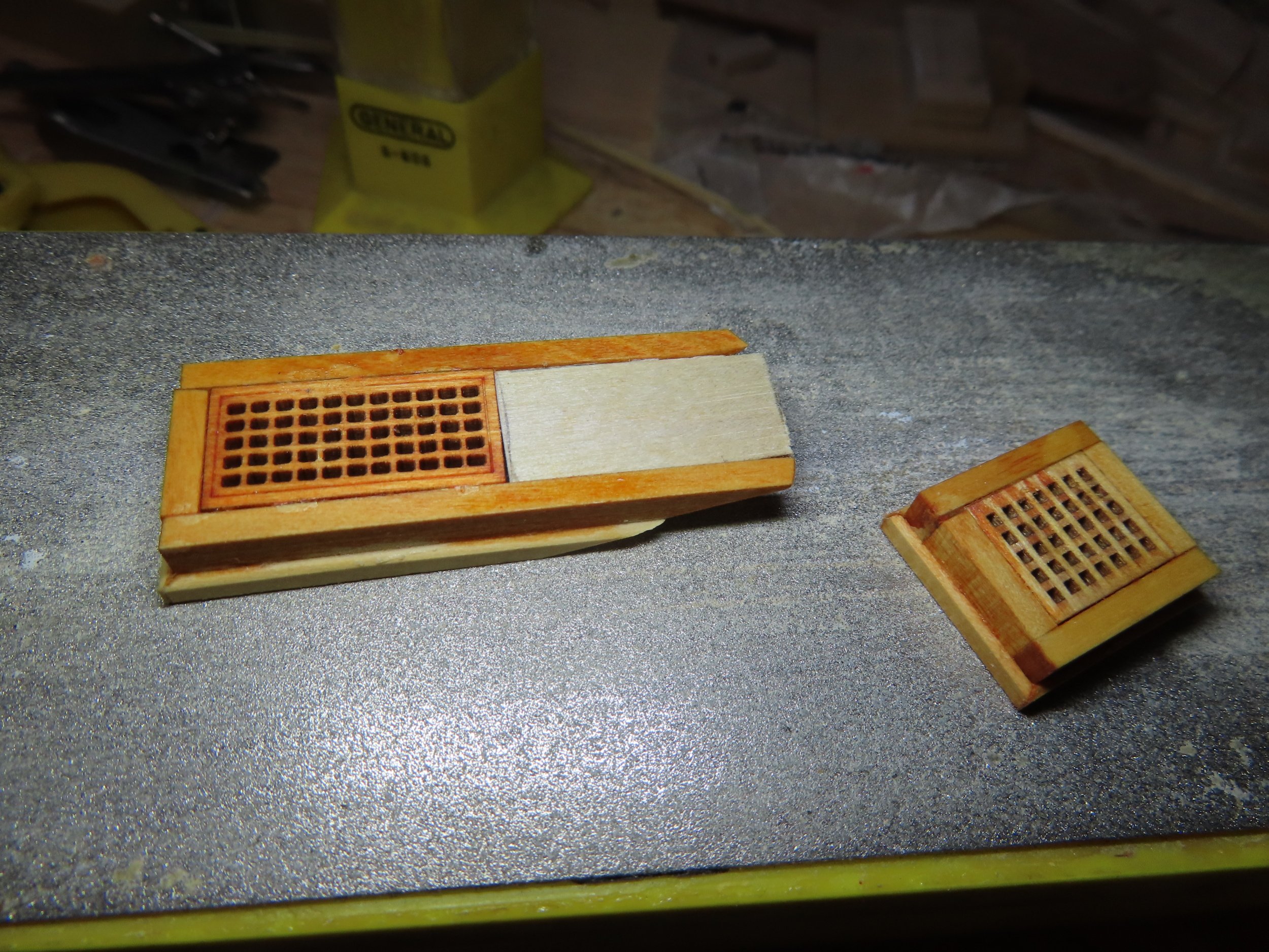
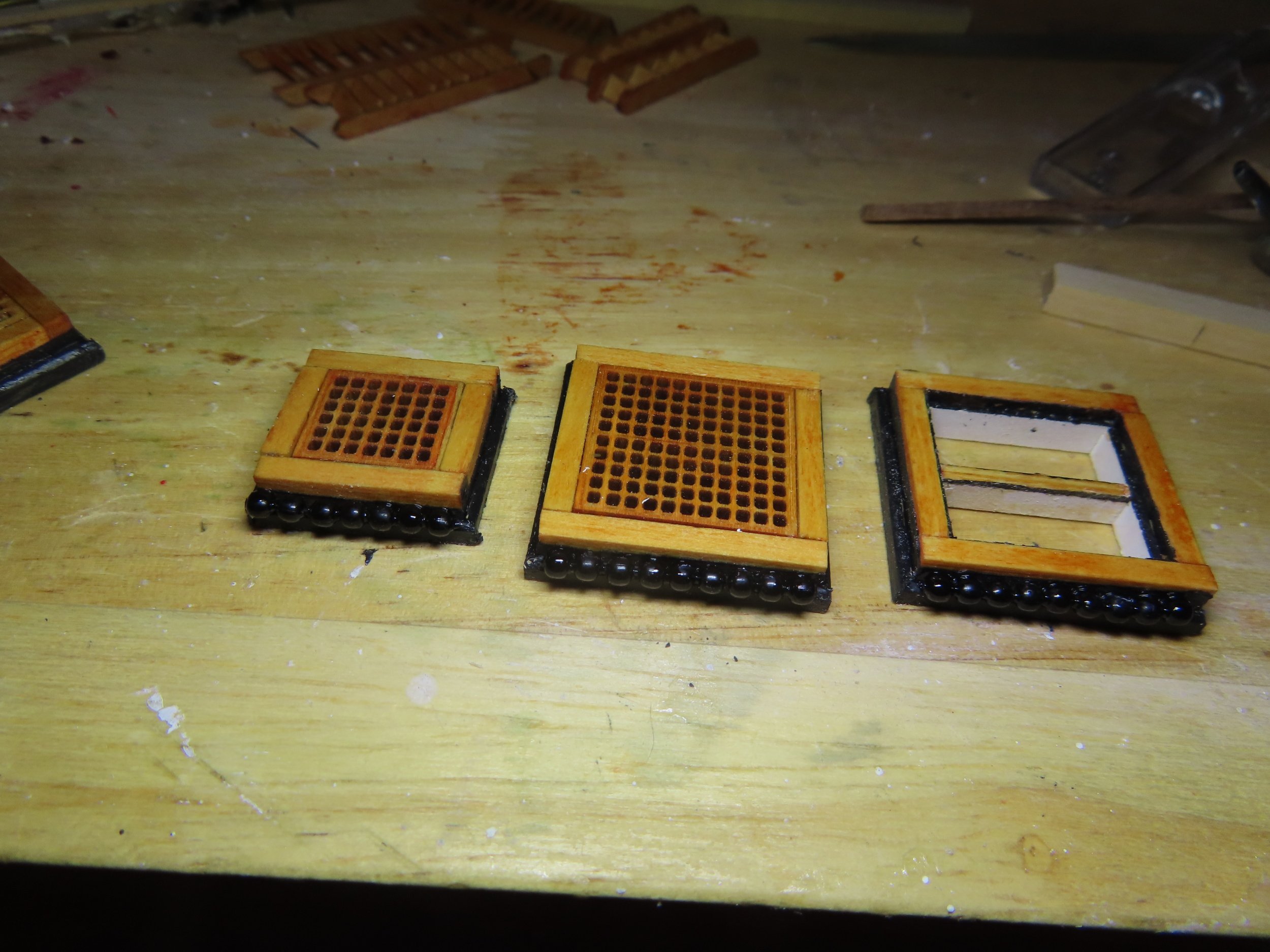
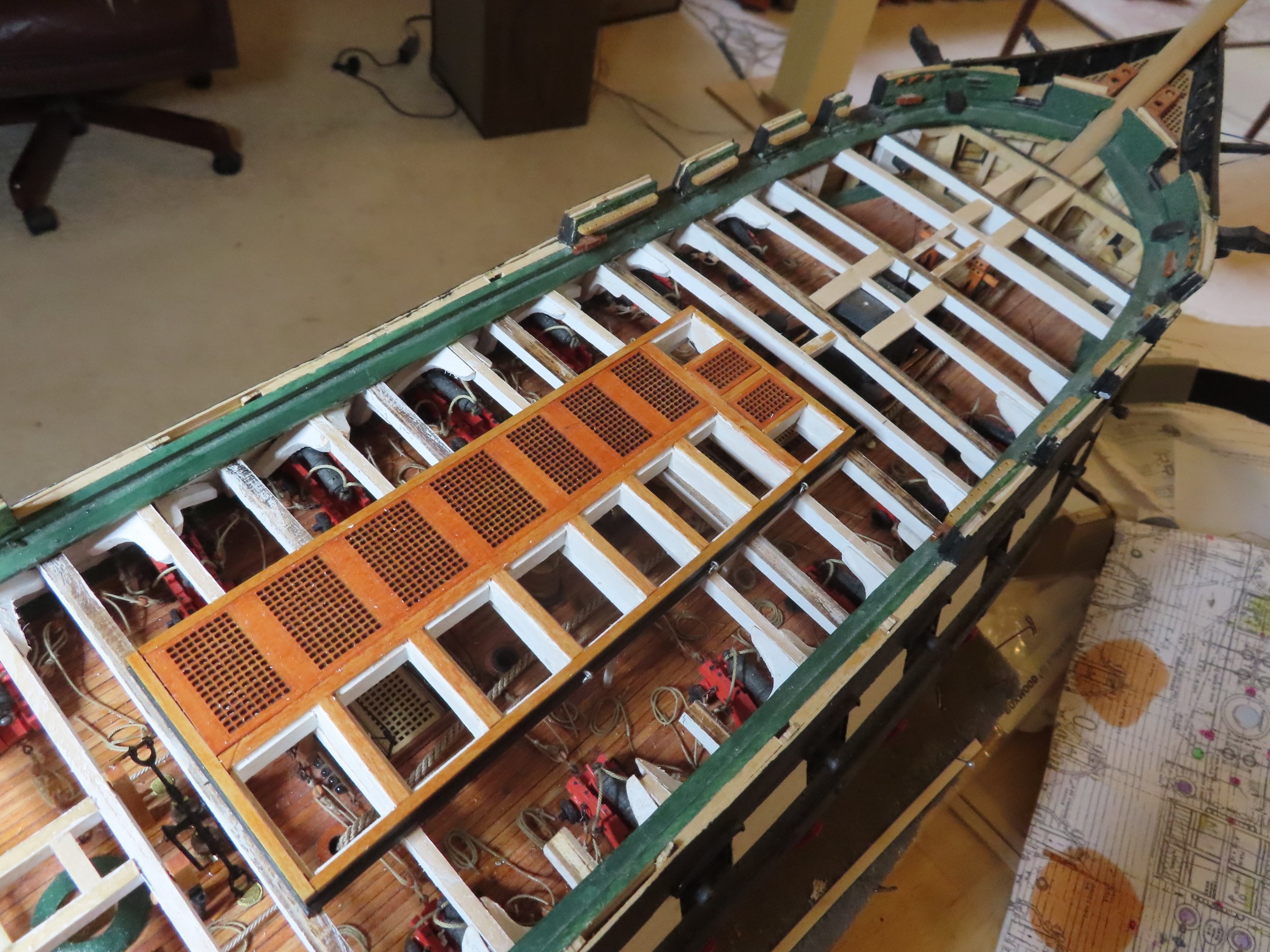
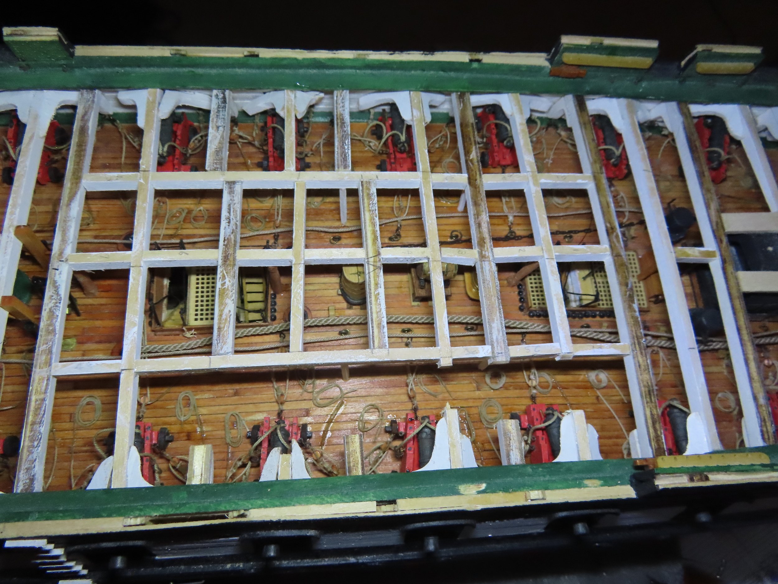
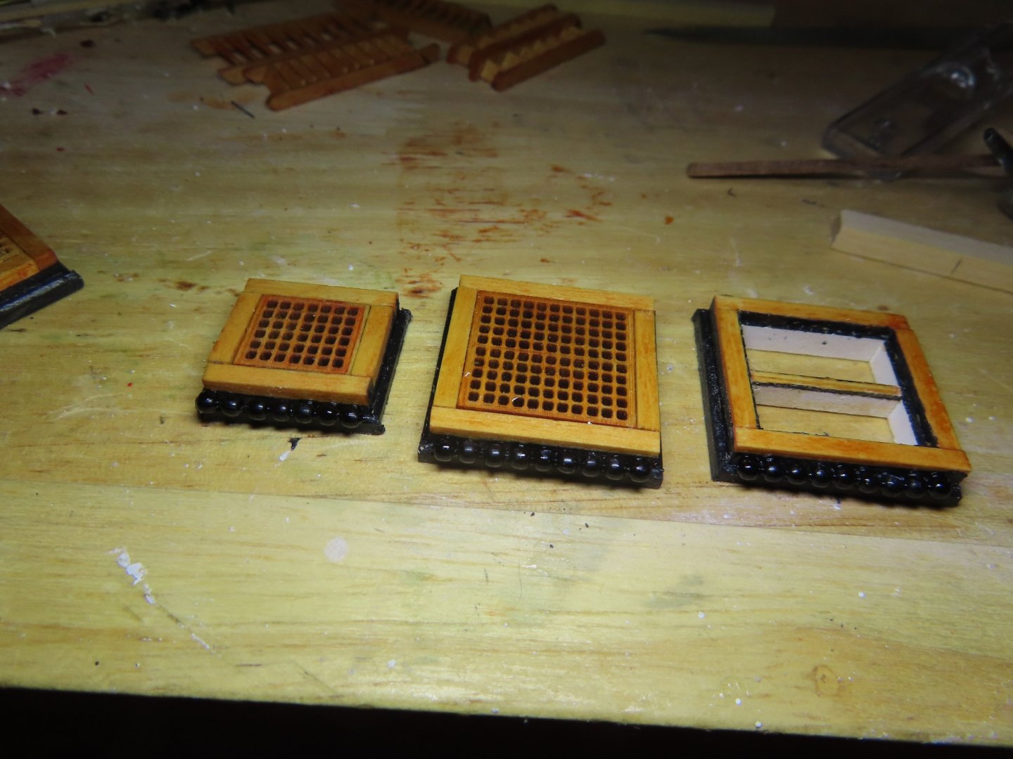
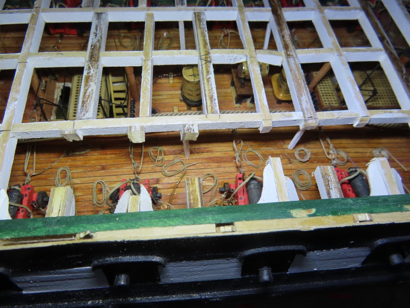
According to the kit’s plans, “shot storage rack: Note all fwd. racks not installed in 1997.” Why, I don’t know. I wanted all the gun crews on my model to have something to load into their guns and shoot. Why should only the aft gun crews have all the fun? So, I installed all the shot racks including the ones omitted from1997. Once again as I did on the gun deck, used a black ball chain. I just sniped off the number of balls I needed off the chain as a unit and glued them into place. The racks themselves are implied as they are way too small to fabricate or see at scale.

-
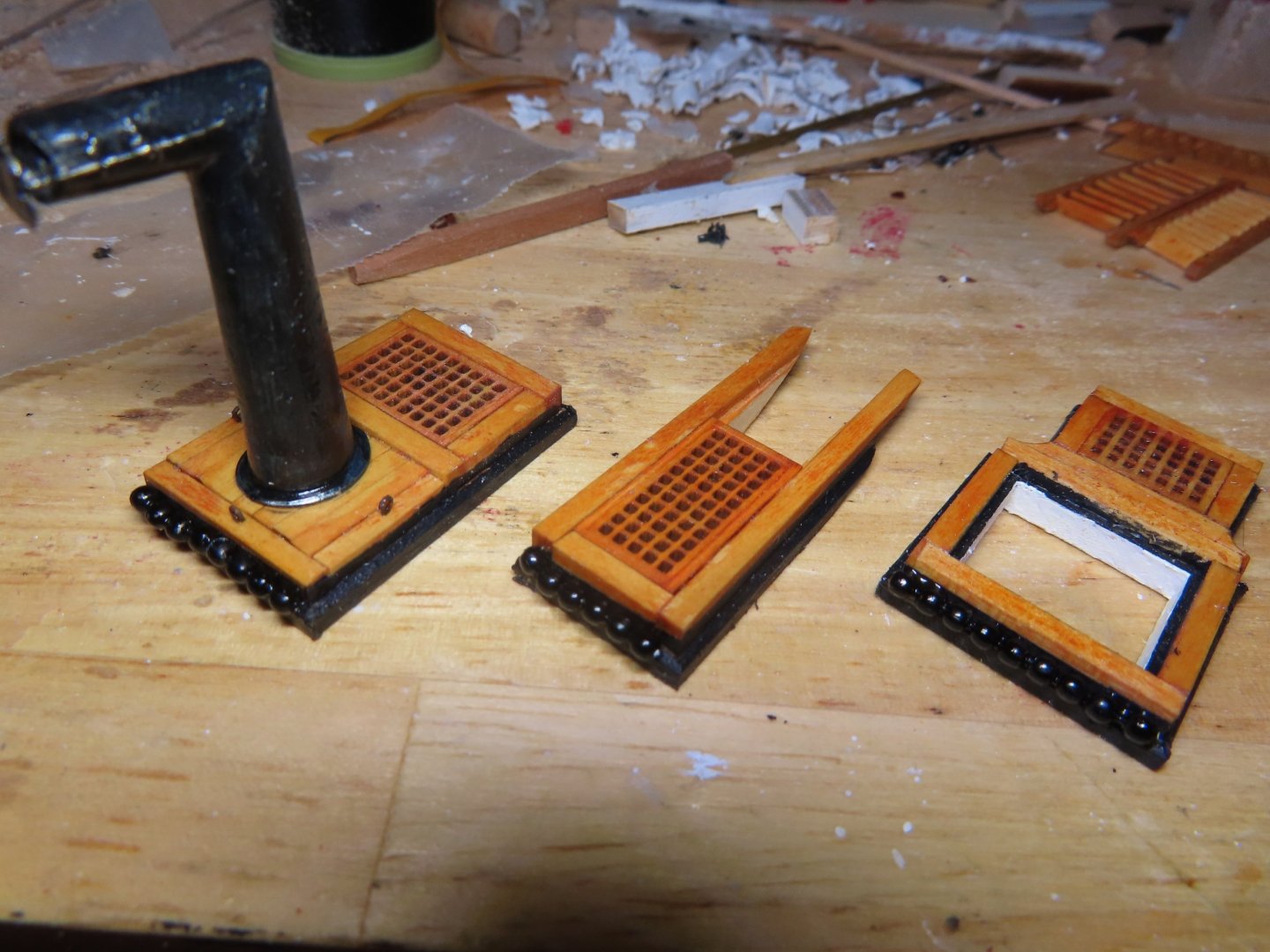
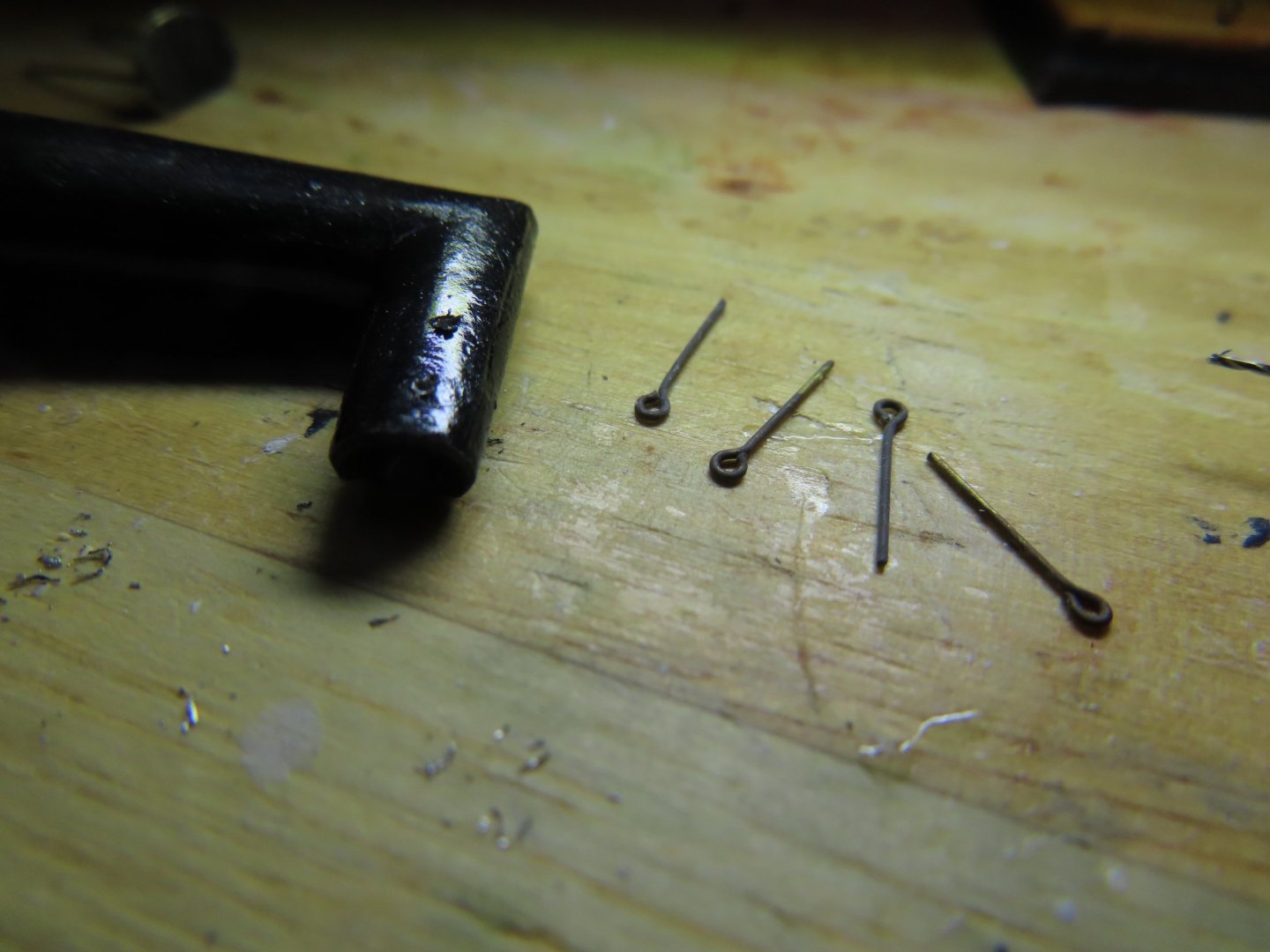
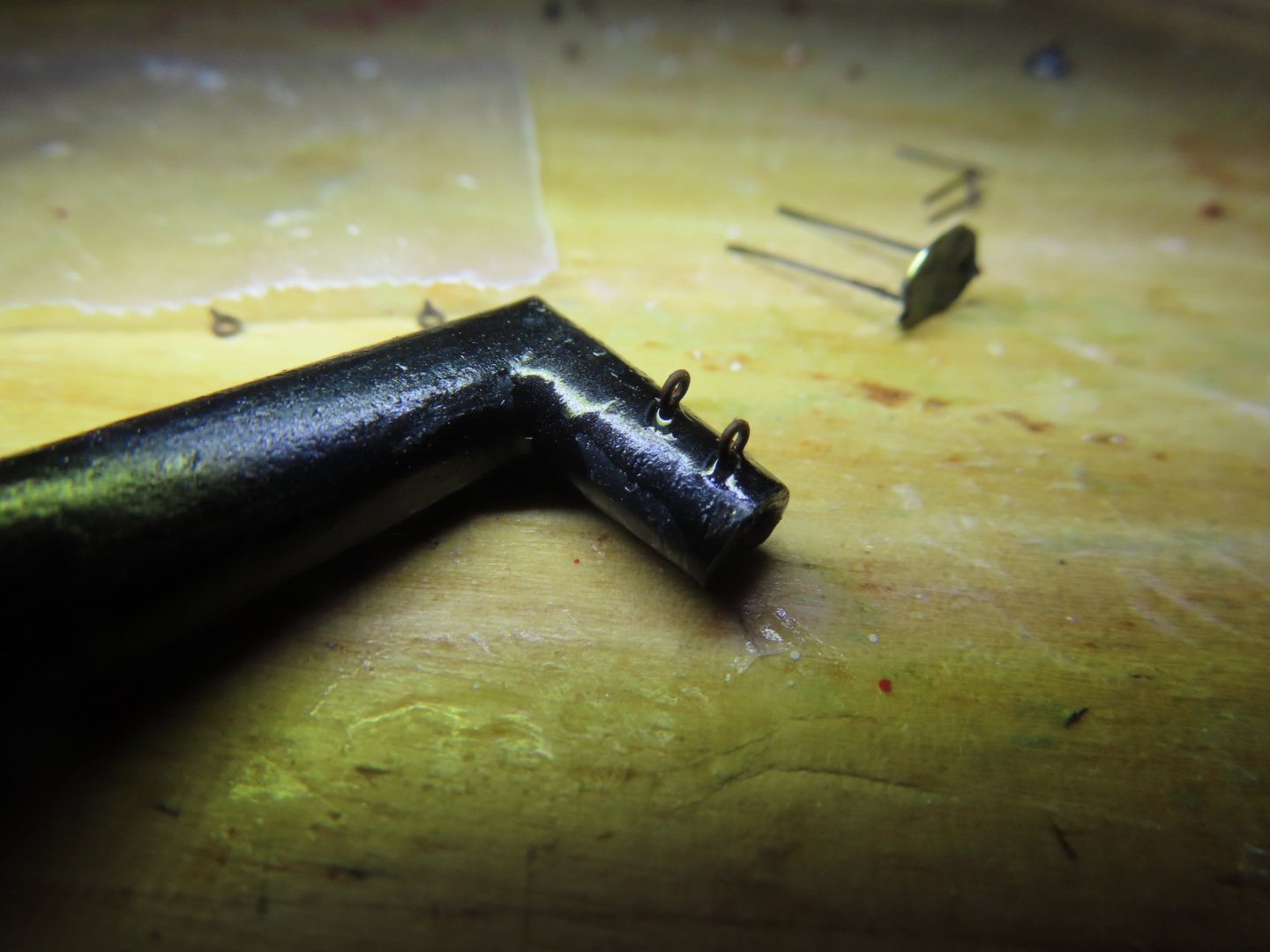
The next problem was how to attach the spark suppressor plate’s support rods onto the pipe? Obviously, I couldn’t use solder as it would end up as a hot puddle of metal. The gluing surface was very narrow, so what glue to use? I had three choices, white PVA, CA, or epoxy. Then I had a flash of inspiration from the actual pipe. I wouldn’t use glue directly but use eyebolts just like the actual stack to mechanically secure the rods. Two 1/32” eyebolts per side supporting the rods threaded through them. A touch of CA glue to secure the eye bolts into predrilled holes in the pipe and a touch of CA glue to secure the rods in the eyebolts. It worked like a charm.

-
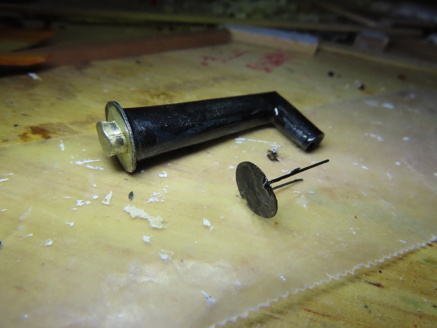
When I fabricated the spark suppressor, I did not realize at the time that the precast pipe was cast with a pseudo suppressor but the gap between it and the pipe was filled in solid, so it looked like part of the pipe. You can see, the pseudo plate is a lip at the end of the cast pipe opening. Therefore, I ground off the lip, hollowed out more of the pipe, and reduced the diameter of the spark plate I had created. The plate and pipe were then painted black.
-
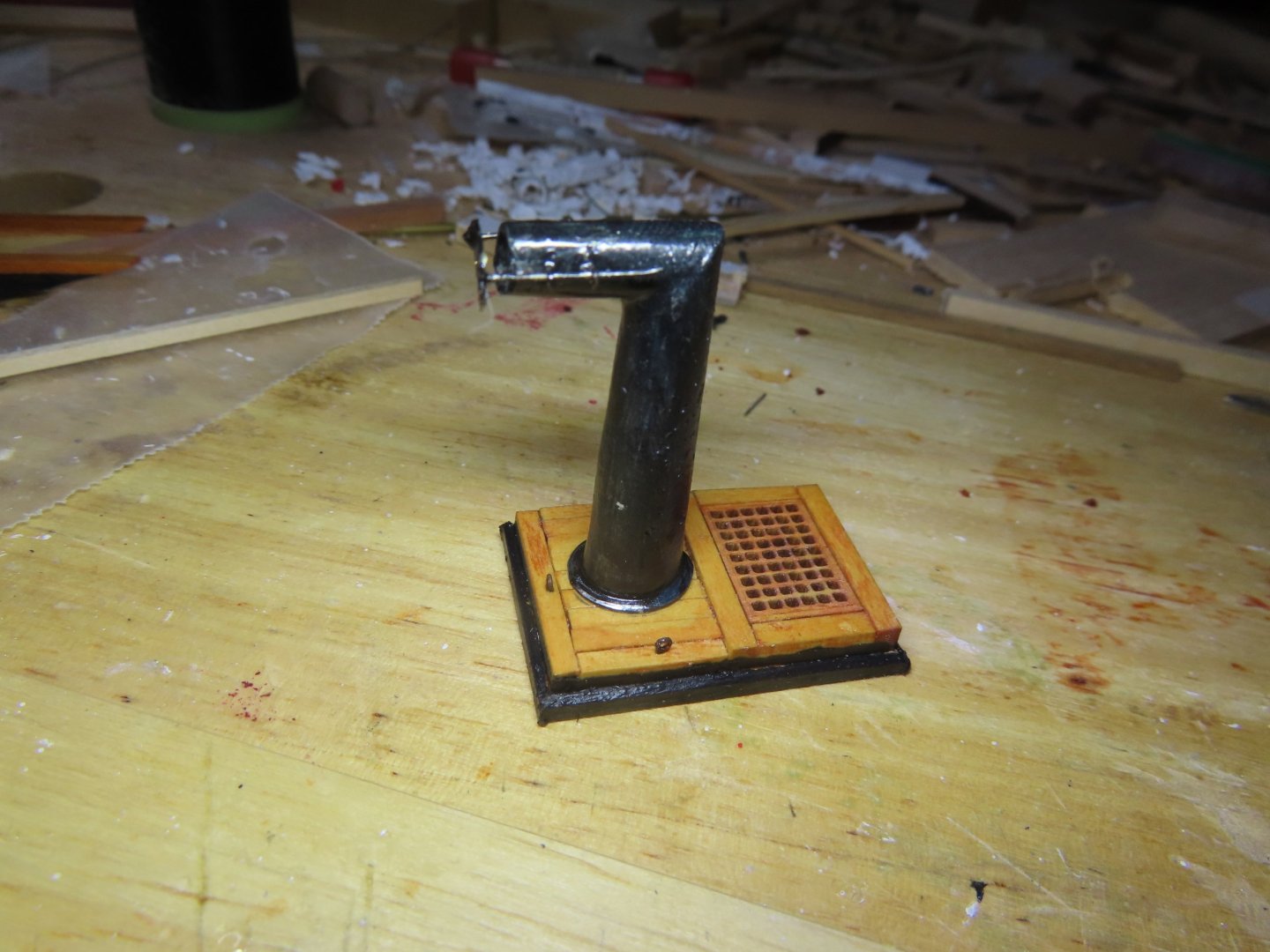
Completing Hatchway Fabrication I did not complete putting the finishing touches on some of the hatchways before, so I started with the stove pipe hatchway, it still required eyebolts, paint, and modification of the precast metal pipe and attachment of the spark suppressor:

-
I don't have any honing stones or experience using them so I looked on YouTube for a how-to and found: this video using a Dremel drill and grinding disk. I'll give it a try. I figured I would need a simple drilling jig, and yours is about as simple as it gets. I had to order some brass rod and tubes, but it appears the USPS may had lost my package. But thanks for your insight. Jon
-
FYI - Because white styrene has a tendency to yellow over time, painting it, is a must. Jon
-
My biggest problem is drilling into the brass. My typical manual twist drills used with a Dremel rotary just don't want to bite into the metal. So making holes into something like those block pieces is a mystery to me. Jon
-
I did not mean to put a cramp in your in your quarter gallery efforts. I just accepted what I did on my model as the best I could do at the time. Your quarter galleries are better than most that I have seen. Jon
-
I never was satisfied with my results after a least 4 attempts too. The result you posted looks great except (and I'm being very picky and wished mine looked as good). your lower panes are larger than the two rows of panes above. They should all be of the same spacing. You got the window frame itself right, something I failed to do. In your post to Mustafa, you mentioned that the glue clouded up the plexiglass. You might try canopy glue, the stuff used to create pseudo glass in small openings. I used mica for my glass. It is strong, clear, and can be made very thin by removing layers by splitting it, is flexible when it that thin, and you can cut it with a scissors. Jon
-
You did a beautiful job on those companion ways. How did you do it? How did you make the cube joints and the finial? I checked xKen's method but I don't have a metal lathe or the skills and experience to use it even if i had one. Jon
-
CCoyle. glad your safe as well. I am surrounded by trees, lots of tall trees, but none fell near me. The ground was littered deep with small branches, leaves, and pine needles; however, a dozen or so trees on my street did come down. Nobody, as far as I know, no one was hurt in my area. There are still isolated pockets of power outages, and the stores are still restocking. But, the worst is over. Take care, Jon
-
USS Constitution by mtbediz - 1:76
JSGerson replied to mtbediz's topic in - Build logs for subjects built 1751 - 1800
You also have something else that is particularly important, skills, patience, and tenacity. It is a pleasure watching you. Jon -
Just a quick update, as many of you know (or not), a major Cat 4 hurricane, Helene passed through Florida, Georgia, and Tennessee, just touching on western South Carolina this passed Thursday and Friday. I live in western South Carolina, a half hour drive to Augusta GA (home of the Masters Golf Tournament), So we got a good taste of the fury that storm packed. I was lucky, and lost power only for two days and had a little erosion damage. Some of my neighbors had more extensive damage to their property. So, I'm OK and am back in the shipyard. Jon
-
USS Constitution by mtbediz - 1:76
JSGerson replied to mtbediz's topic in - Build logs for subjects built 1751 - 1800
A very neat look compared to mine. Well done! Jon -
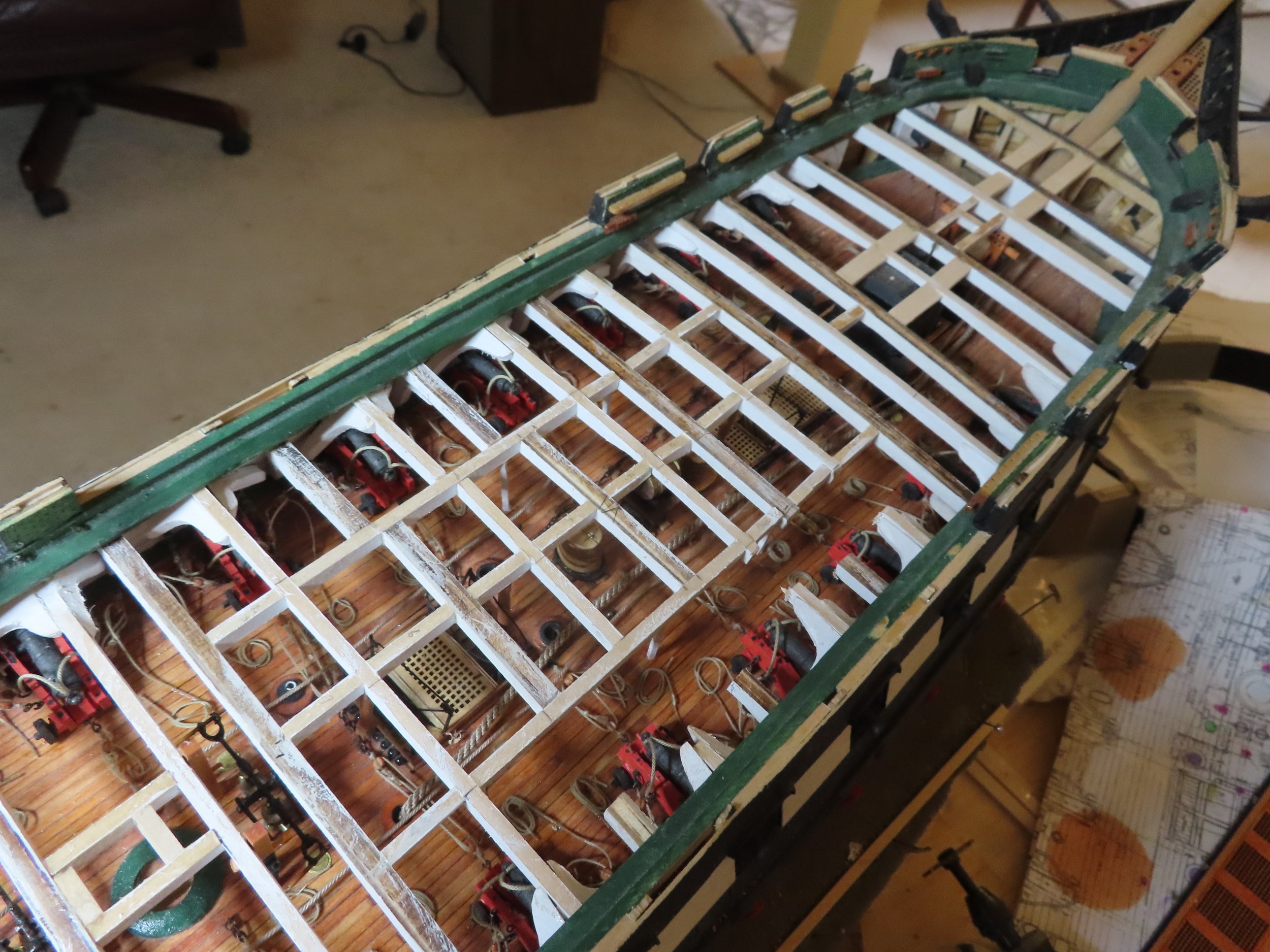
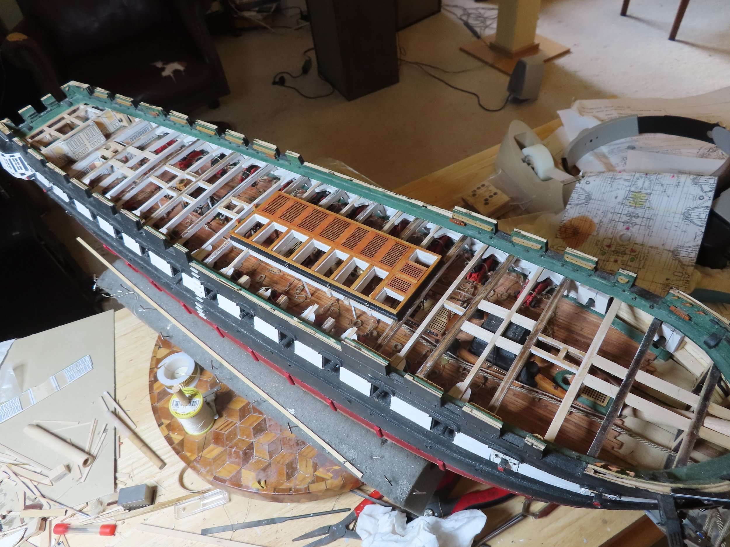
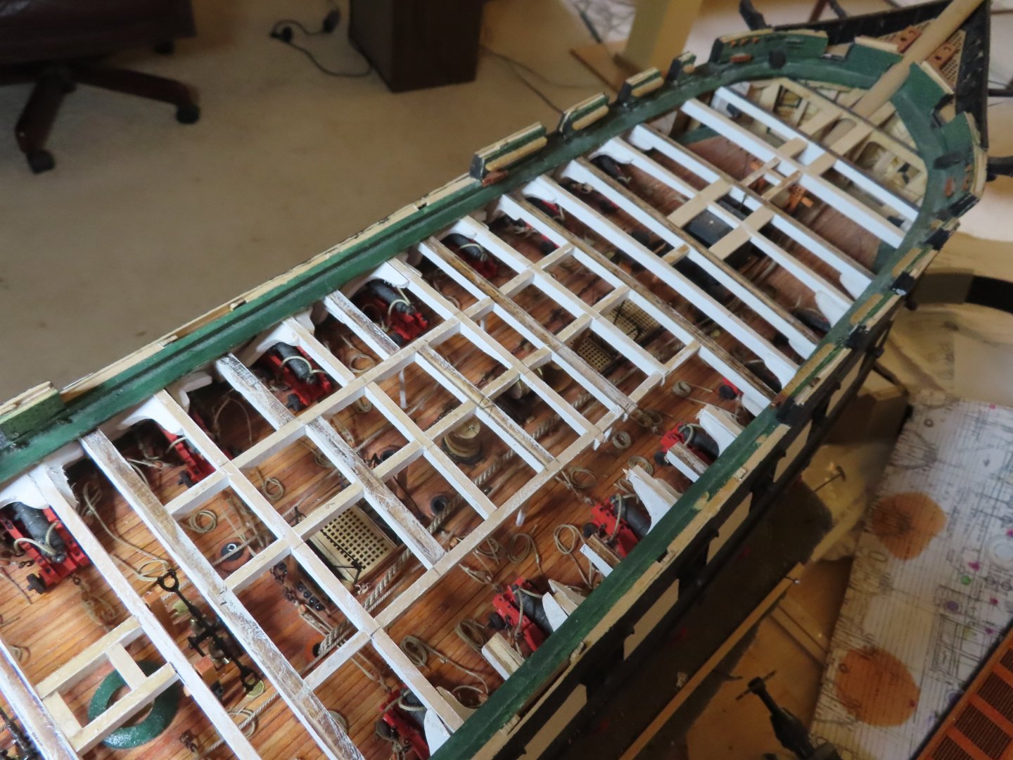
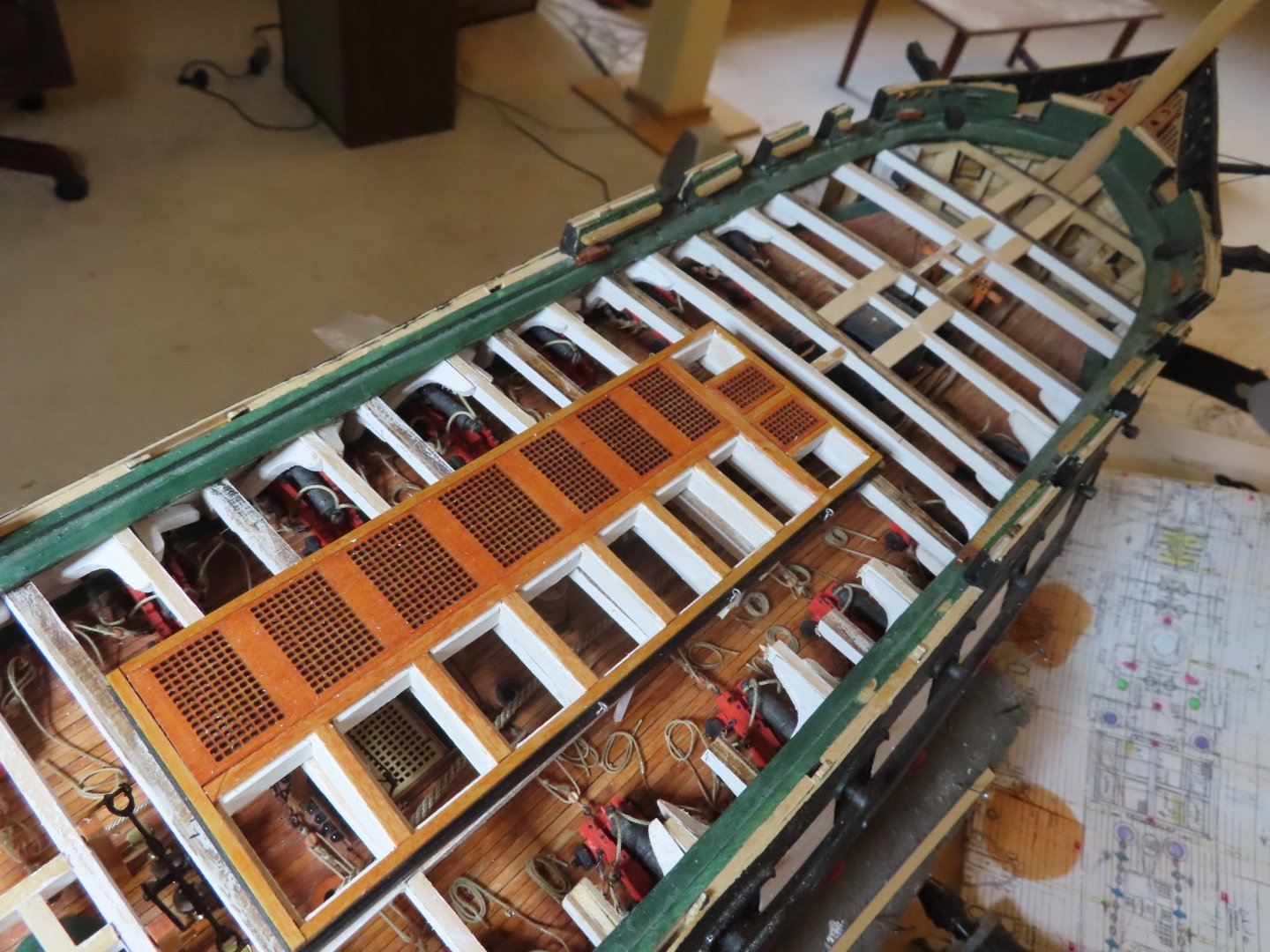
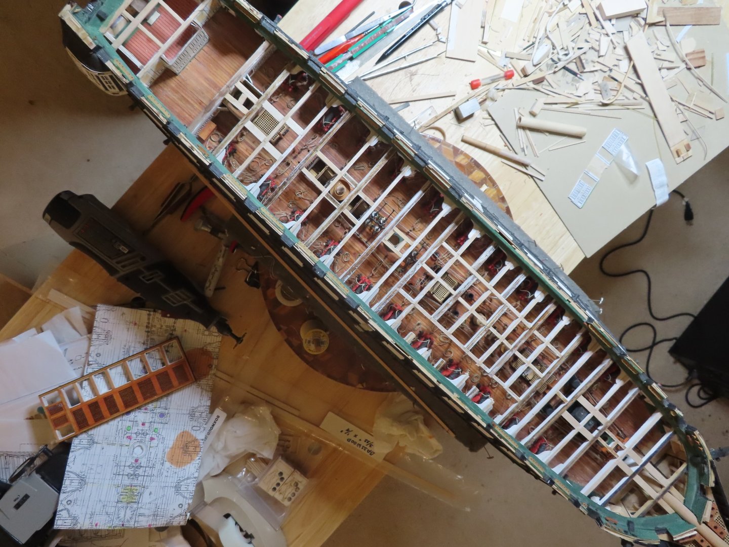
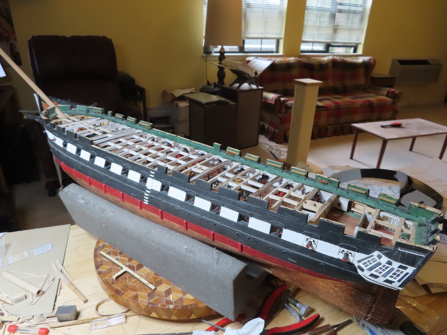
This post shows more of the same. I added more spar deck beams, gun deck columns, both the white square cross section ones and the natural wood round ones, knee braces, and the main hatch framing support beams. You will notice that the starboard side is missing some beam sections. I realized that even though I did not add all the spar deck structure, viewing the gun deck was getting a bit obscure. To alleviate this a little, I made it look like the beams were cut out. However, I made this discission after I had installed three whole beams supporting the main hatch. The beams were cut, the leftover stubs were left in place. Where I intentionally installed partial beams, I added little stubs to make it appear they were cut after most of the picture were taken. Additionally, you may have noticed that the beams under the main hatch do not run straight across. This is my solution to the problem I discussed in an earlier post about the structure of the main hatch. The laser cut grids making up the main hatch do not conform to any plan I’ve seen including the kit plans. In keeping with the idea of the cut-away look, the top surfaces of the structural beams and supports were not painted so it would look like the spar deck planking was removed revealing raw timber below. A side effect of this is where there will be planking and other things items attached to them, the glue works better on bare wood. Some of the pictures below show the main hatch dry fitted in position


-
USS Constitution by mtbediz - 1:76
JSGerson replied to mtbediz's topic in - Build logs for subjects built 1751 - 1800
Very creative with the furniture! Well done! Jon -
Hey, I'm a life long 77 year old bachelor with no one to answer to except myself and the cat, so I've got time to gather stuff and organize it for easy retrieval. I try to share the wealth. Jon
-
Now I know what my model should look like! Nice job!! Jon
-
I have approximately 25,500 images of the ship from the very earliest in 1857 to the present showing all kinds of detail from multiple angles and multiple sources (public & private) that I have collected since about 2014. Should you or anyone else need a image showing particular detail, there is a good chance I may have it. Just ask. Jon