HOLIDAY DONATION DRIVE - SUPPORT MSW - DO YOUR PART TO KEEP THIS GREAT FORUM GOING! (89 donations so far out of 49,000 members - C'mon guys!)
×


JSGerson
-
Posts
2,629 -
Joined
-
Last visited
Content Type
Profiles
Forums
Gallery
Events
Everything posted by JSGerson
-
 Transom Trim Continued Double arch The practicum chose not to use the laser cut double arch molding because they: Became very fragile once removed from the laser cut board Were square cross section whereas the actual molding is half circle cross section Were difficult to shape and sand As much as I wanted the trim to be made from wood, it was much more practical to follow the practicum guidance and use white 0.060" half round styrene. Like the practicum directed, I used the kit's laser part to pencil in a faint line across the transom where the styrene piece was to go. By holding the laser cut piece in place with one hand, I traced around one edge with the other marking the curvature on the transom with a pencil which you can just see in the second image. The first image below shows the actual transom as a reference.
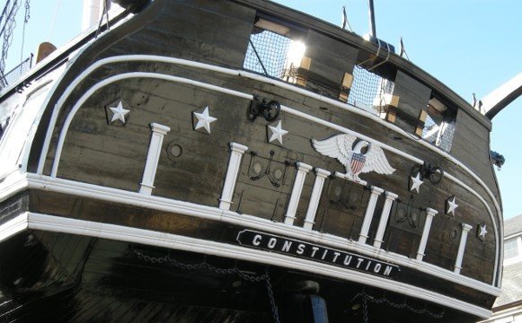

-
Very nicely done. Just be extra careful once the gun port lids are installed onto the hull. I would wait until the last possible moment before installing them. The open lids are fragile and are easily knocked off. Are you going to paint the interior face of the lids black like the contemporary images show? Jon
-
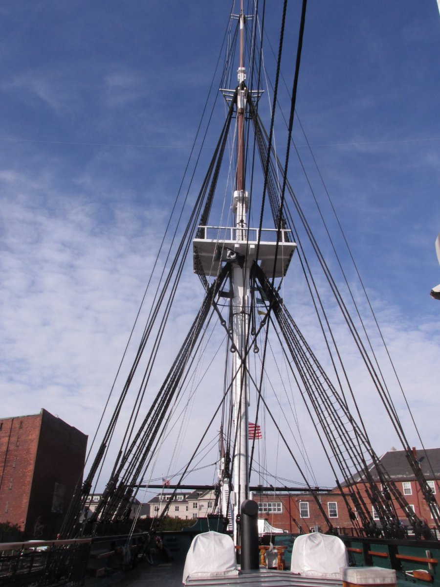
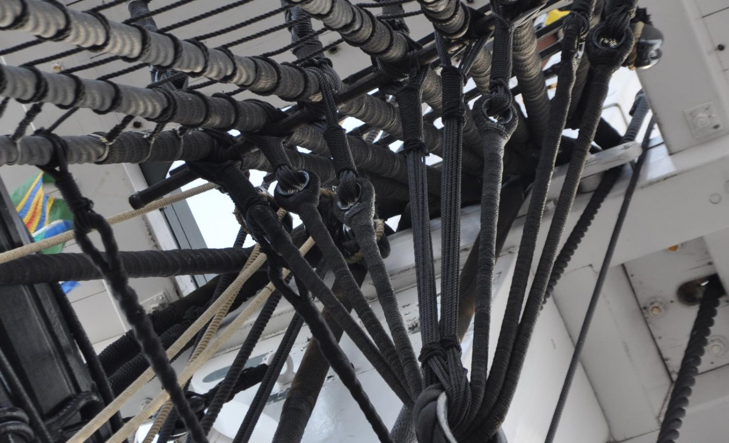
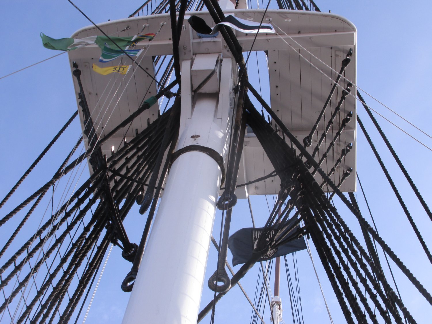
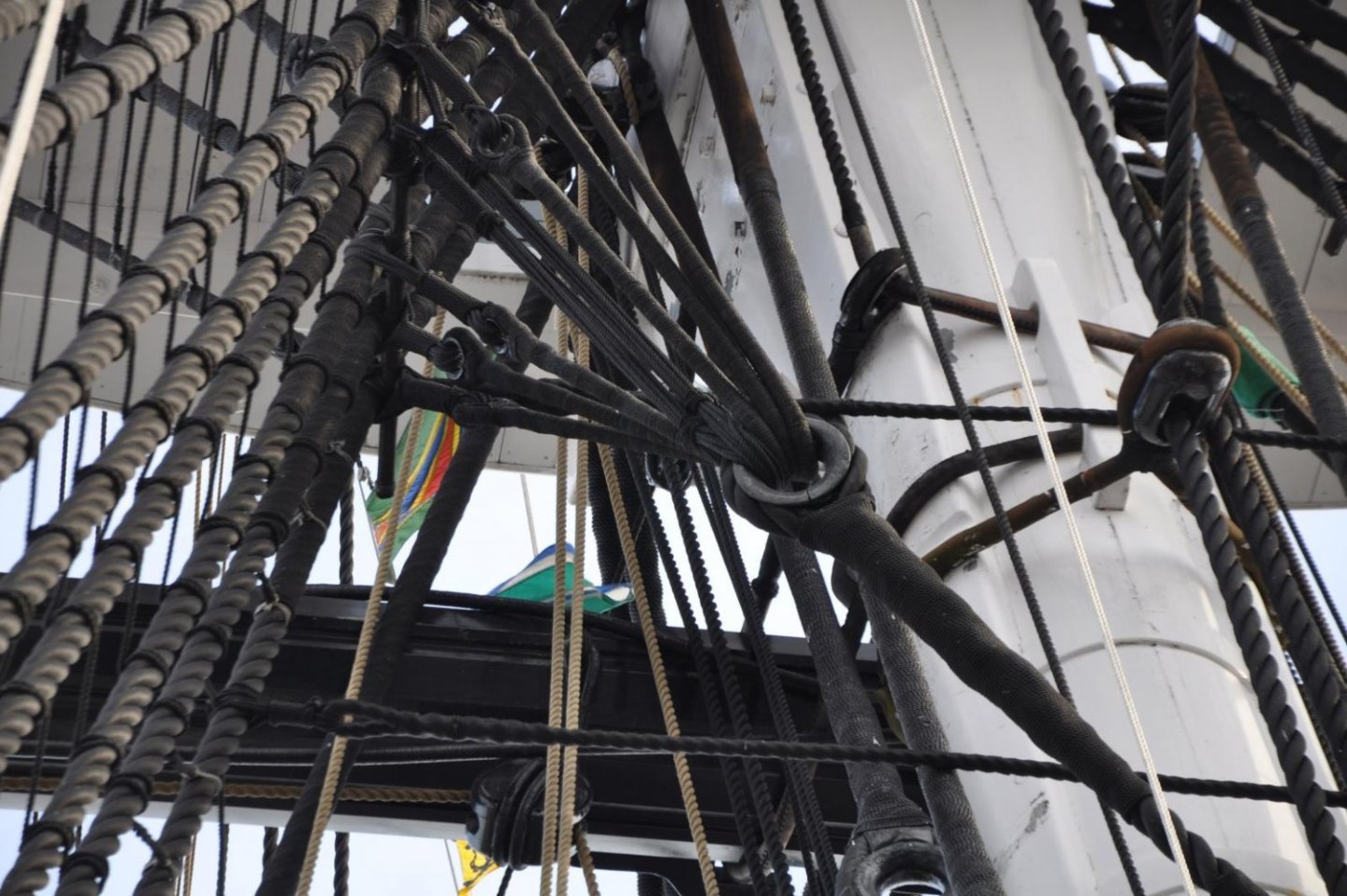
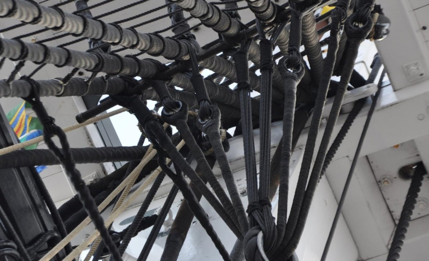
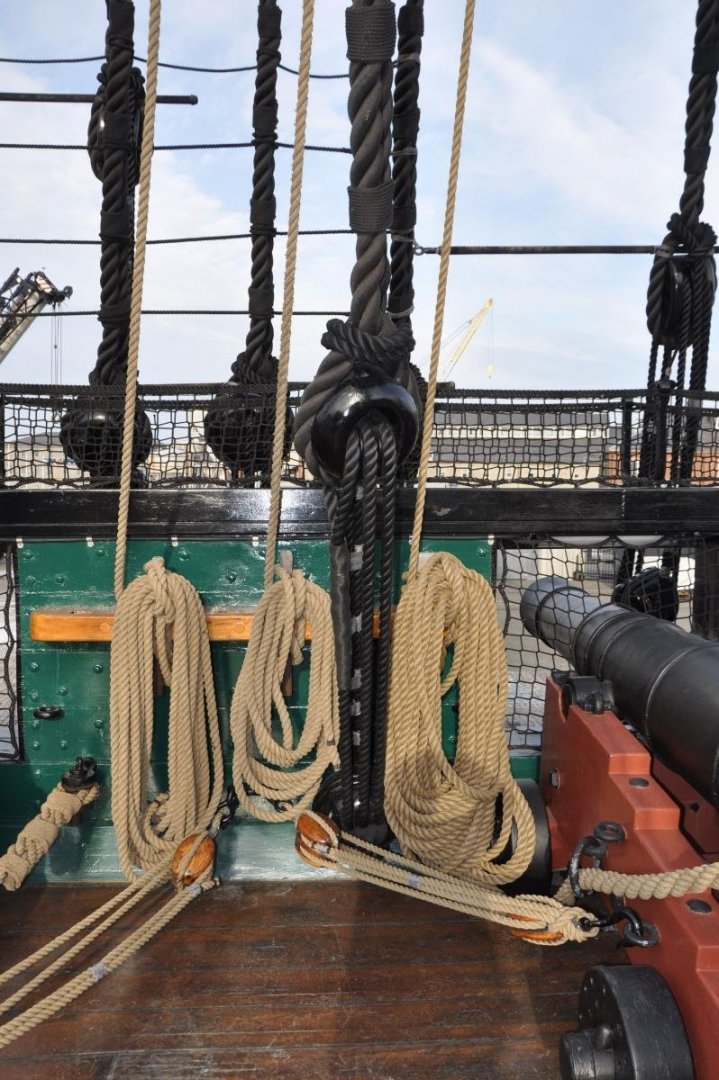
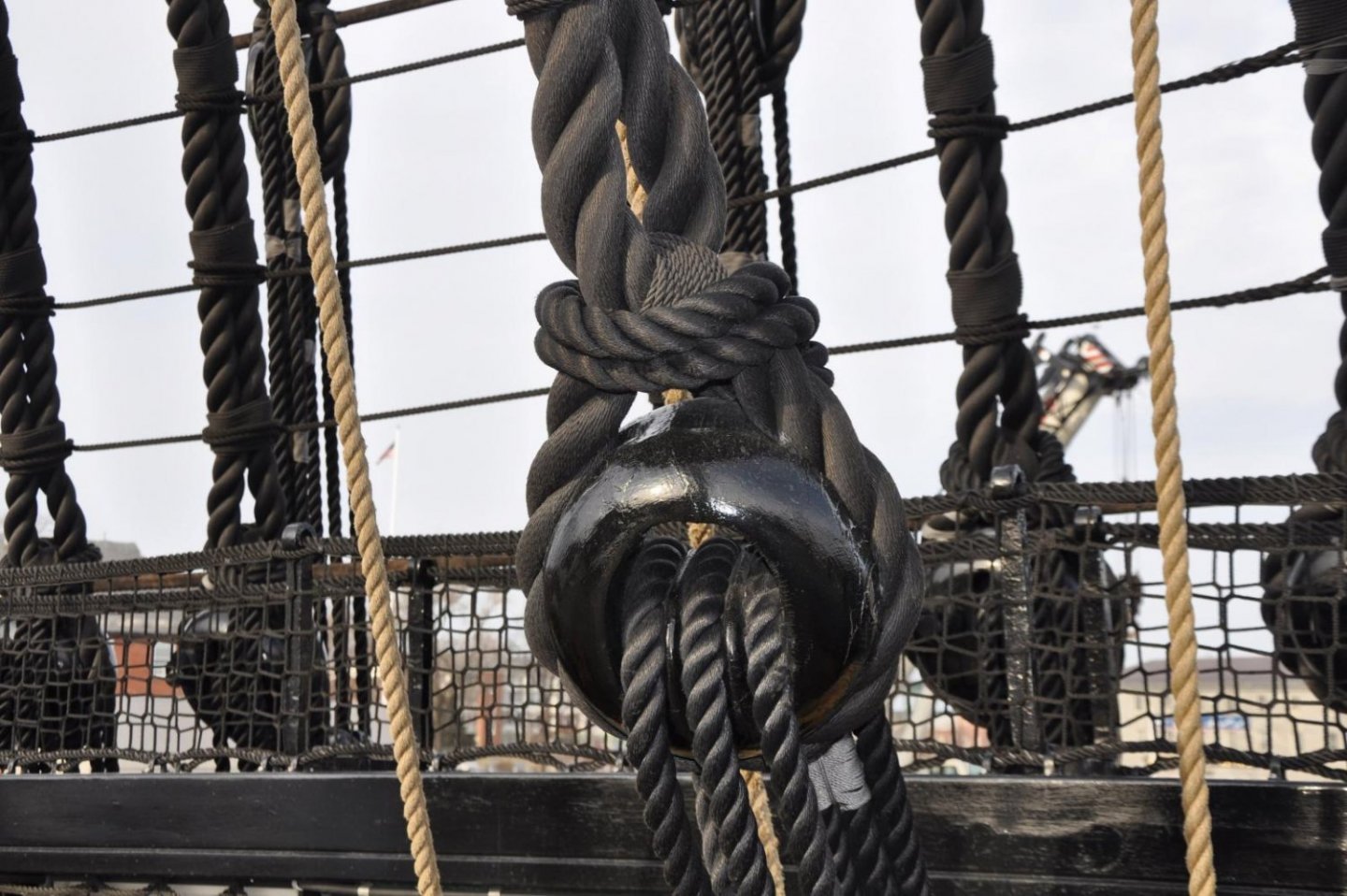
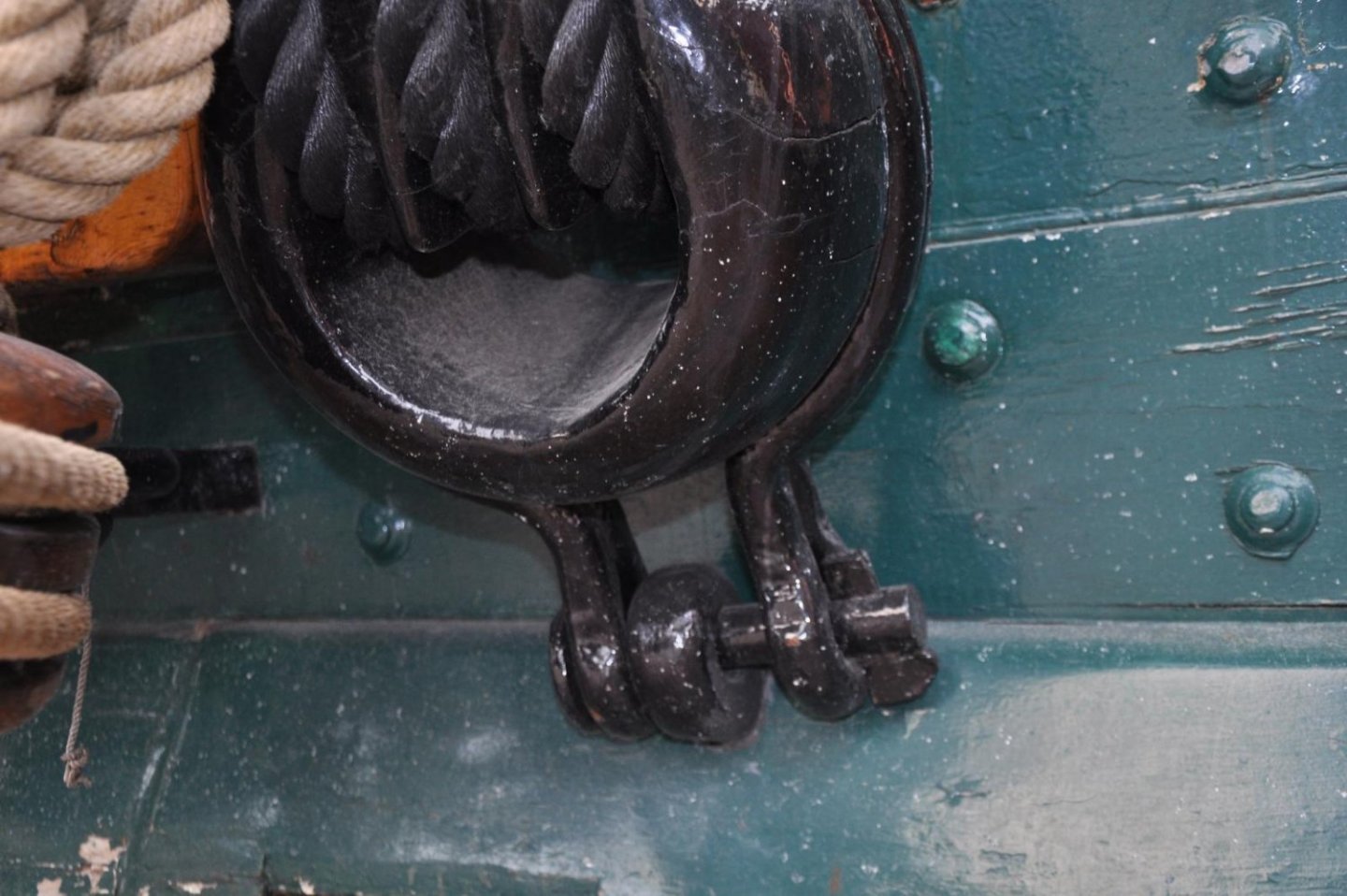
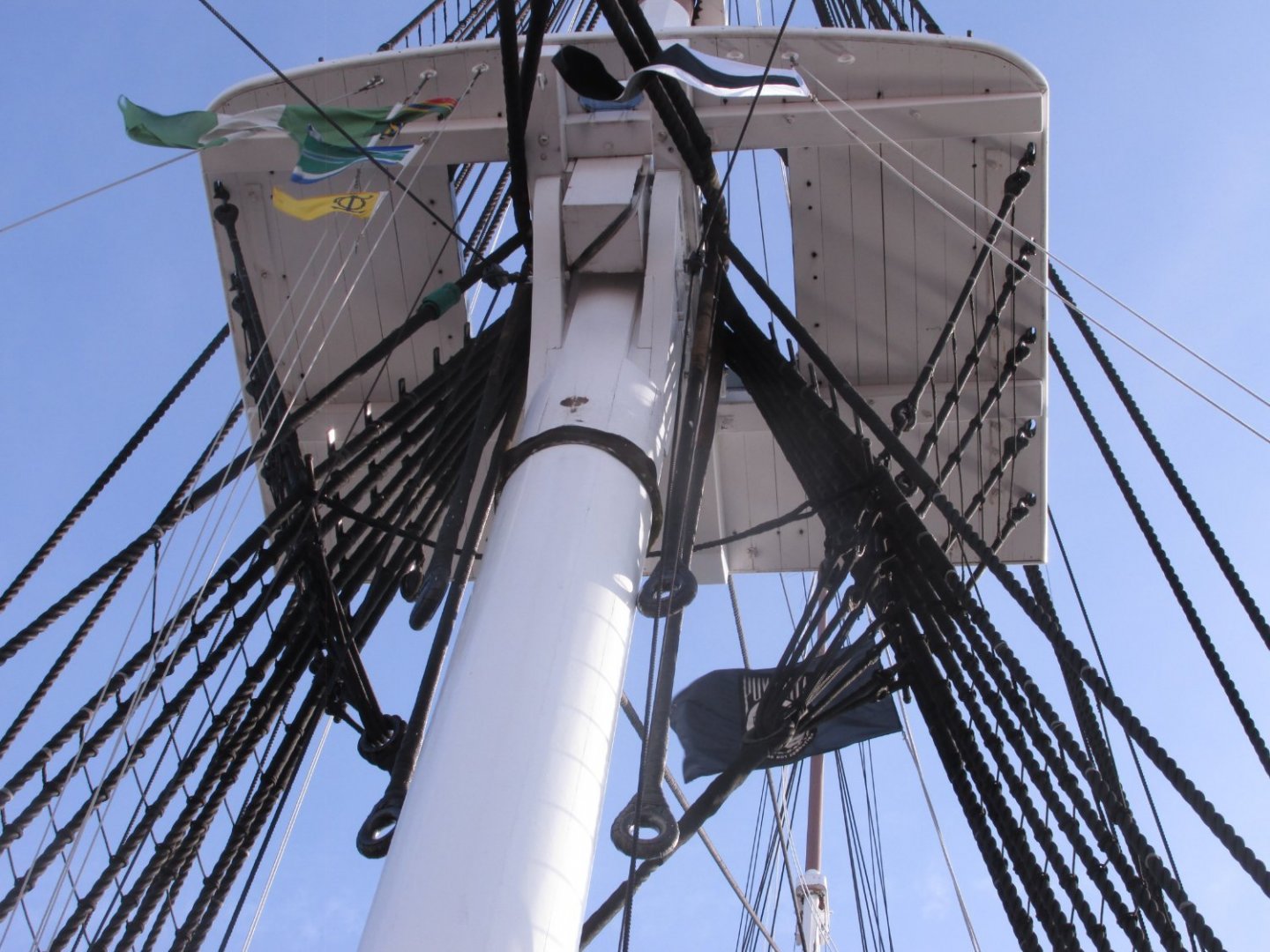
Tom, those "heavy lines which end in thimbles are called Burton Pendants. From David Antscherl's book, "The Fully Framed Model, Rigging a Sixth Rate Sloop of 1767-1780" Vol IV: “Burton Pendants are served lines that were slipped over the mastheads prior to stepping the lower masts in full-sized practice. Blocks and tackles were then attached to them for hauling up to the tops and other items of rigging.” They are an essential part of the ship. I have collected a vast photo library for my build of the Constitution. Here are some images of the bentinck shroud rigging and burton Pendants that I have. Jon


- 163 replies
-
- 2
-

-
- Model Shipways
- Constitution
- (and 2 more)
-
Thanks Bob
-
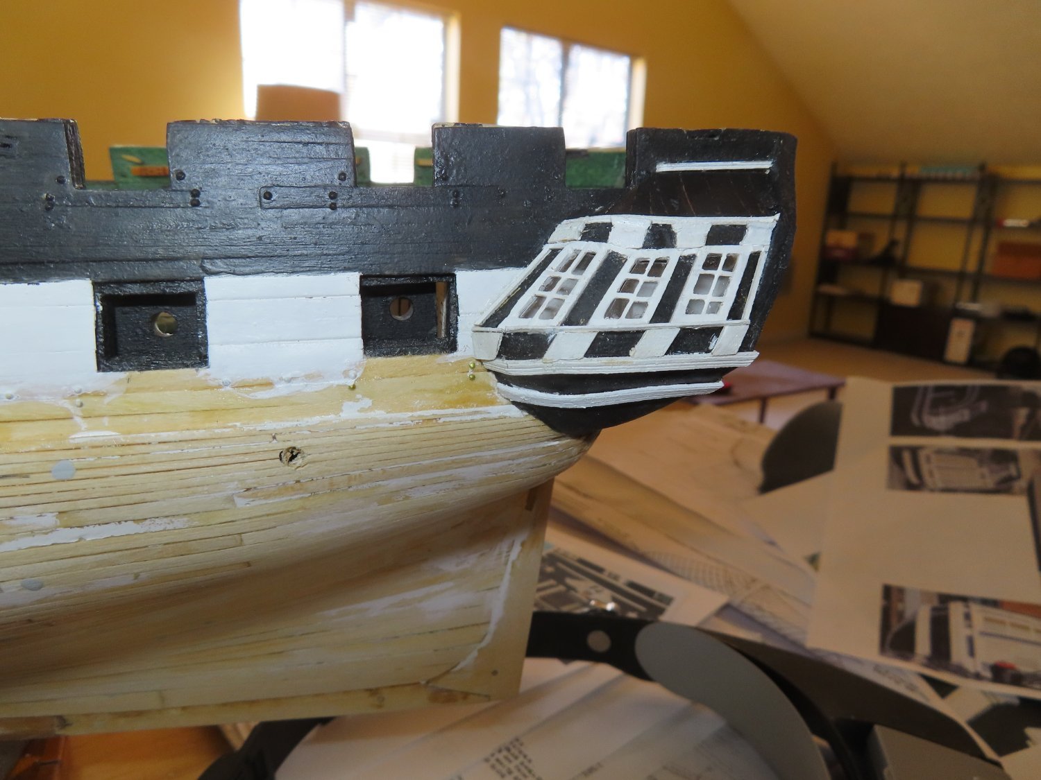
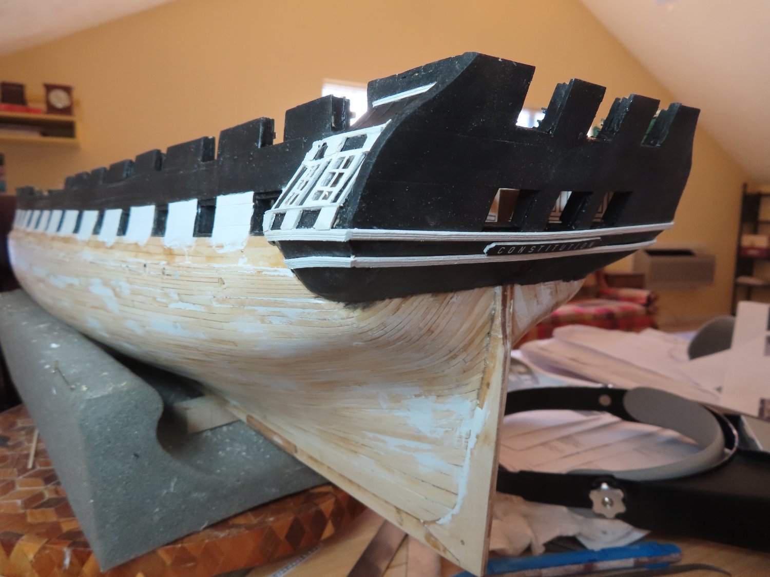
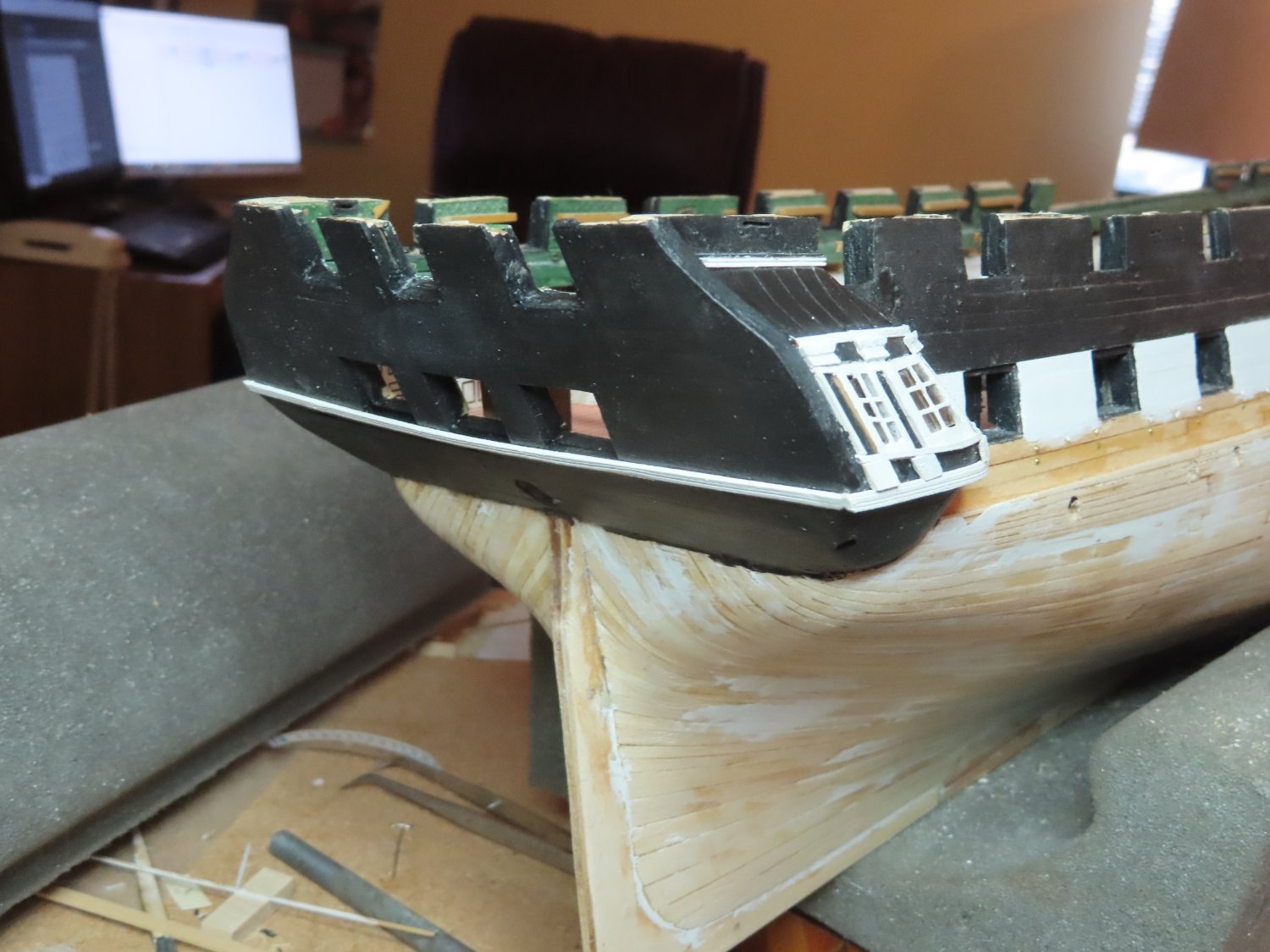
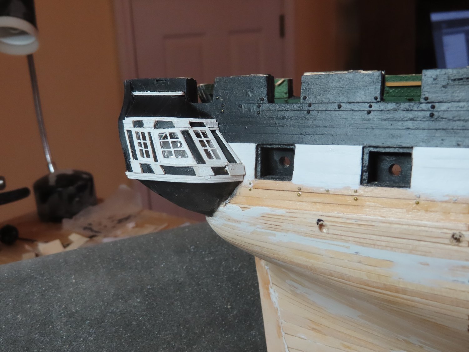
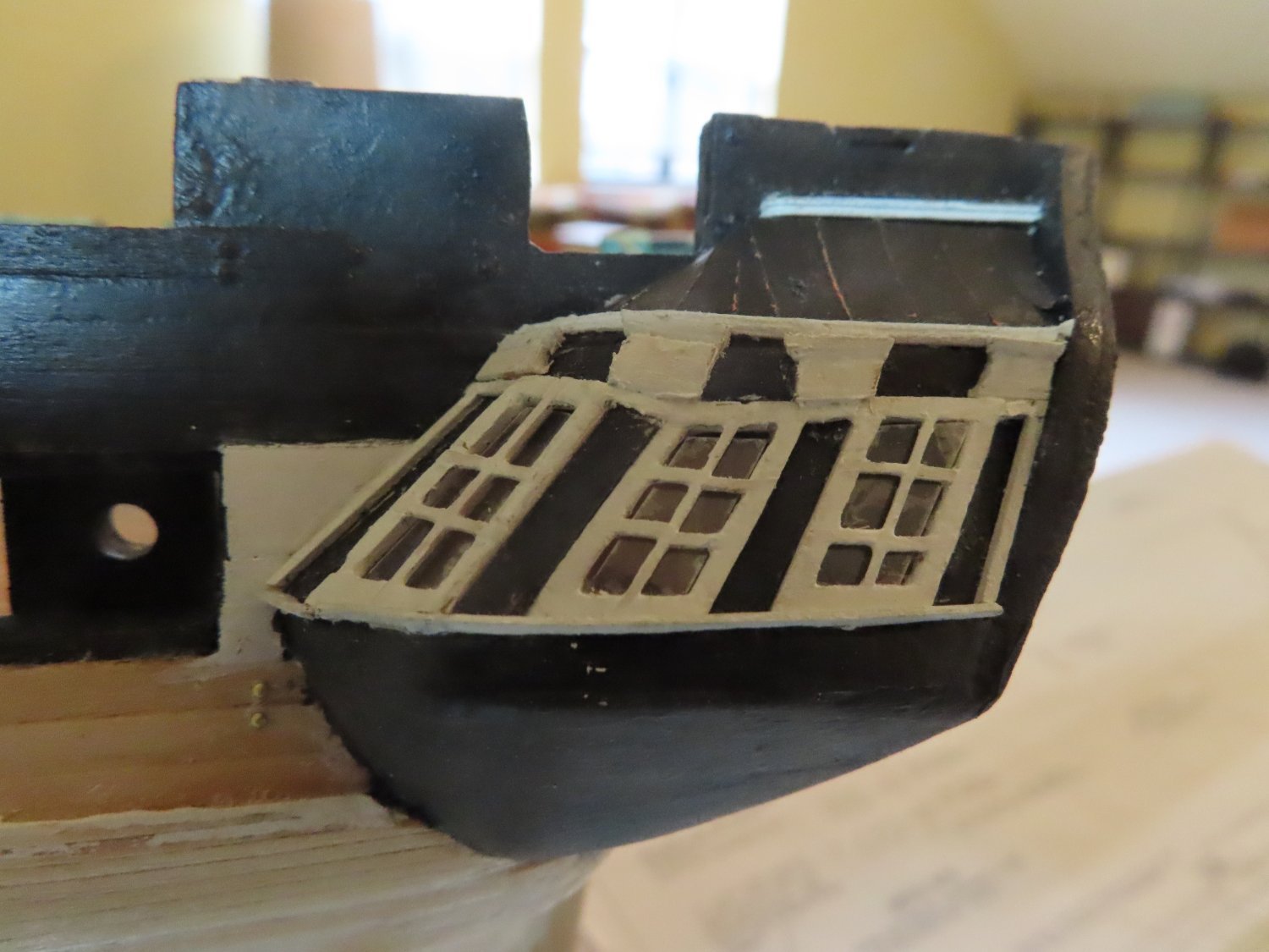
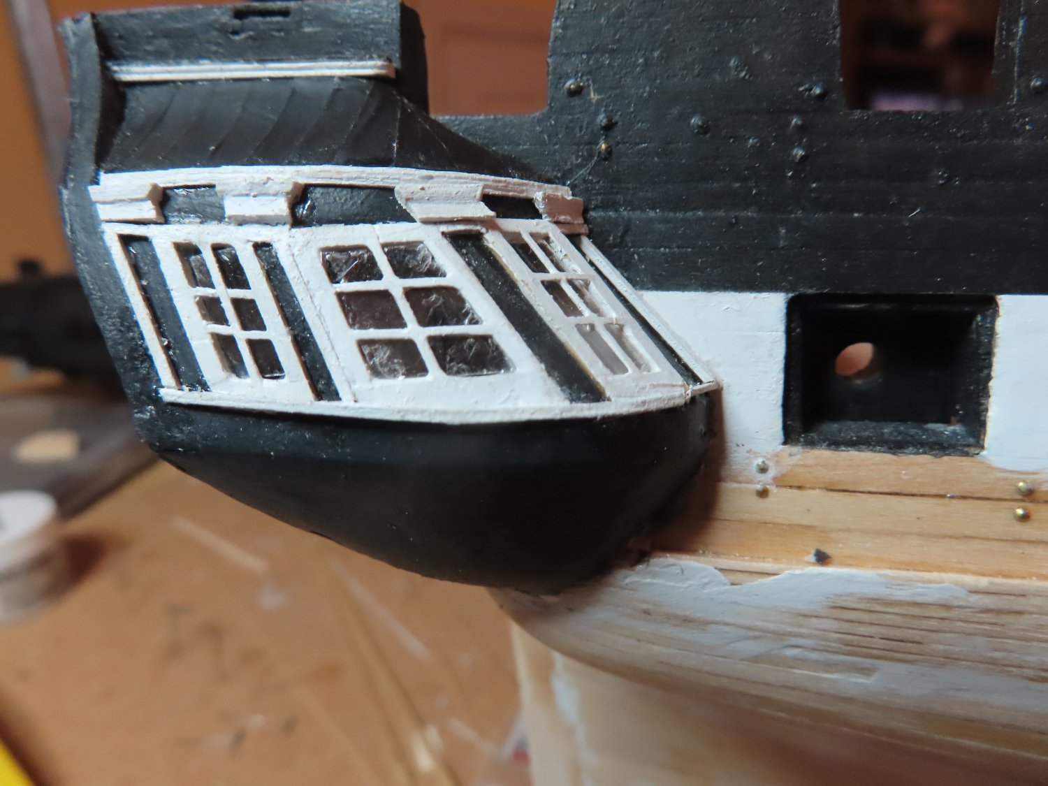
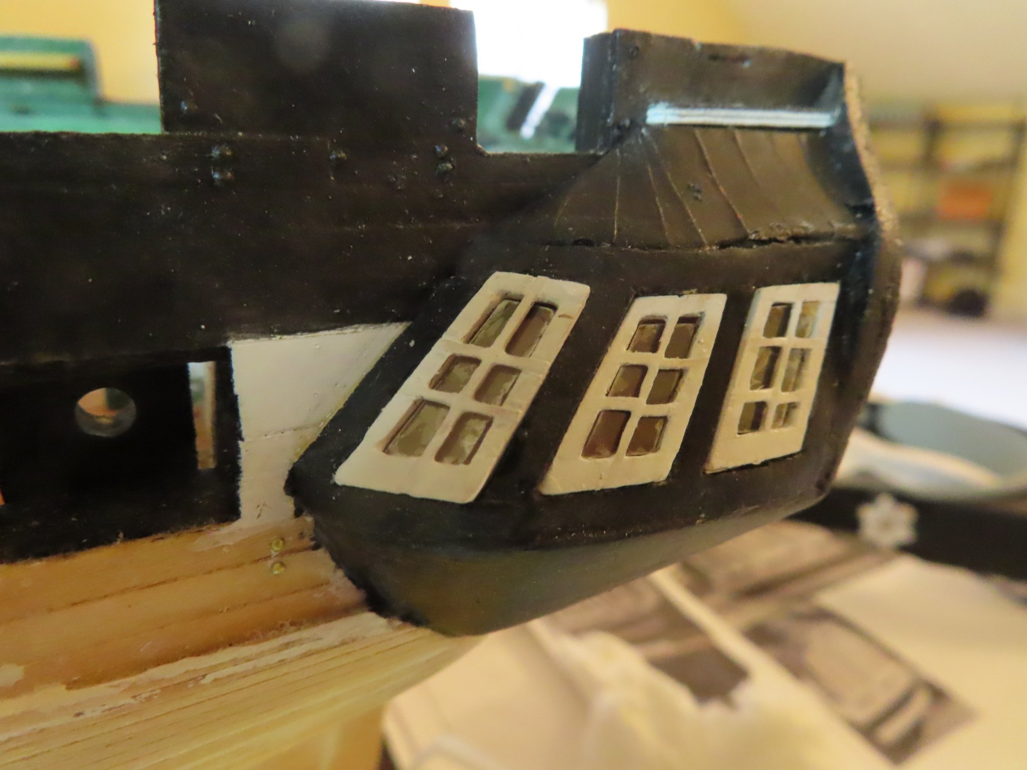
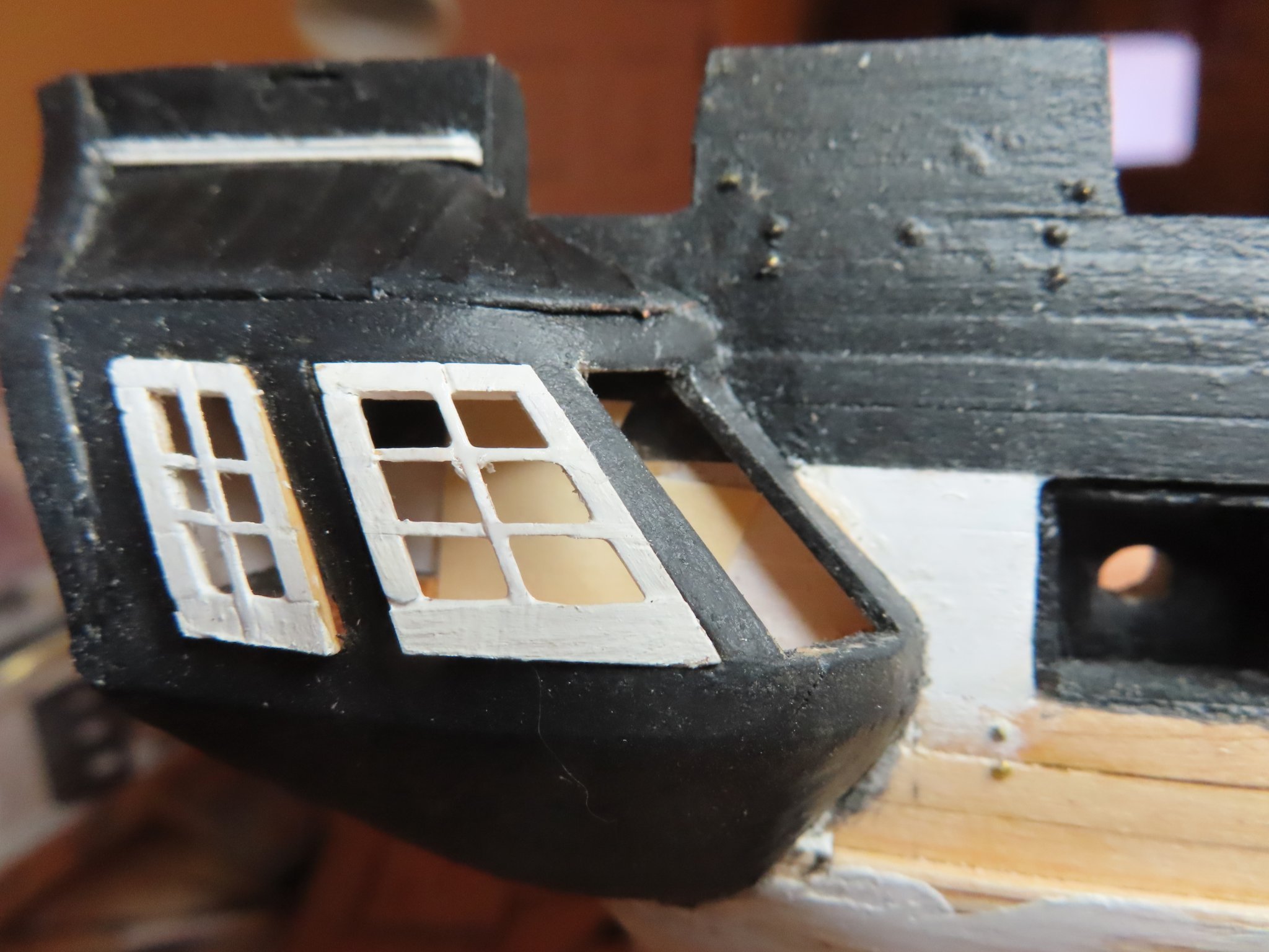
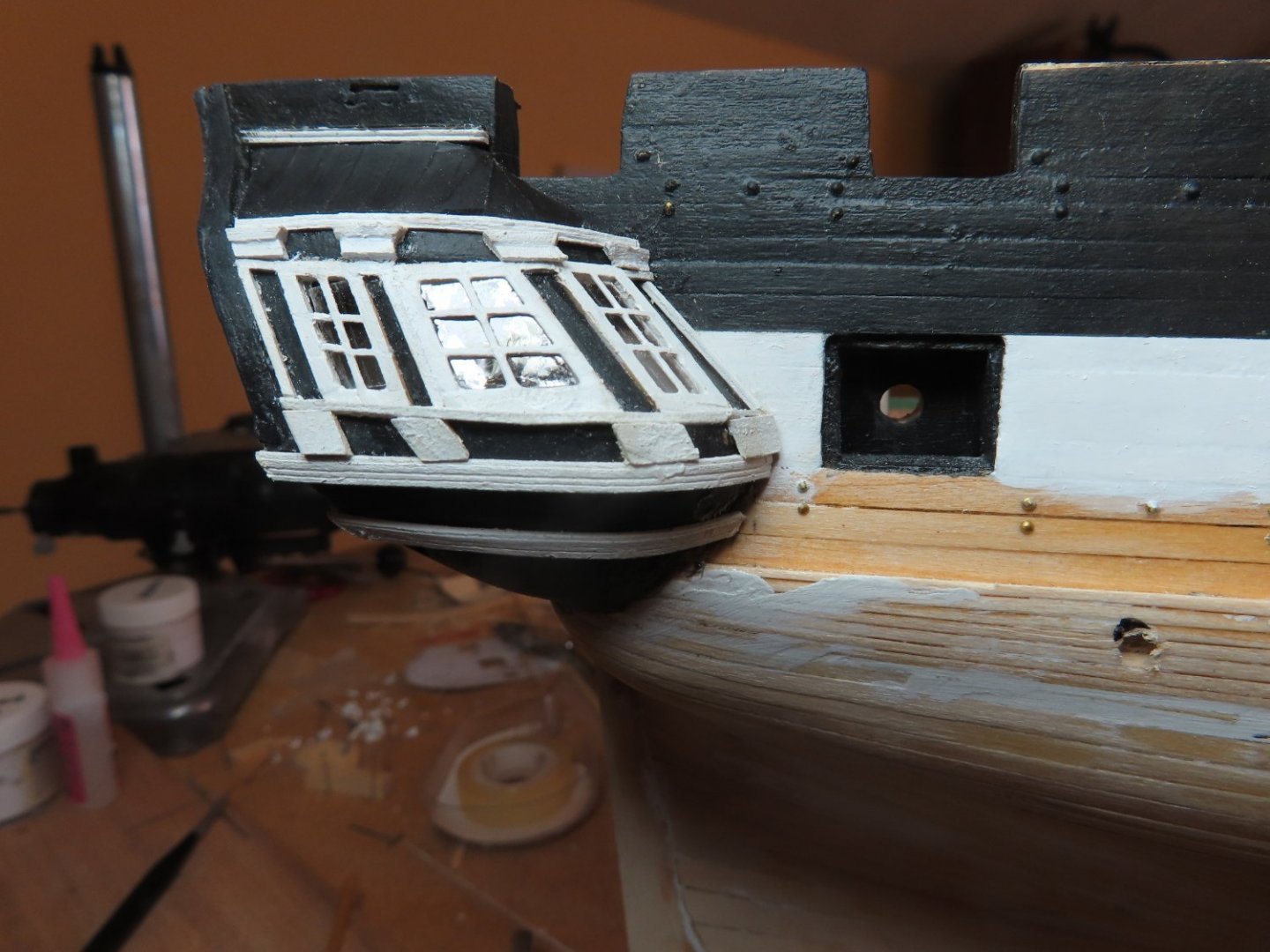
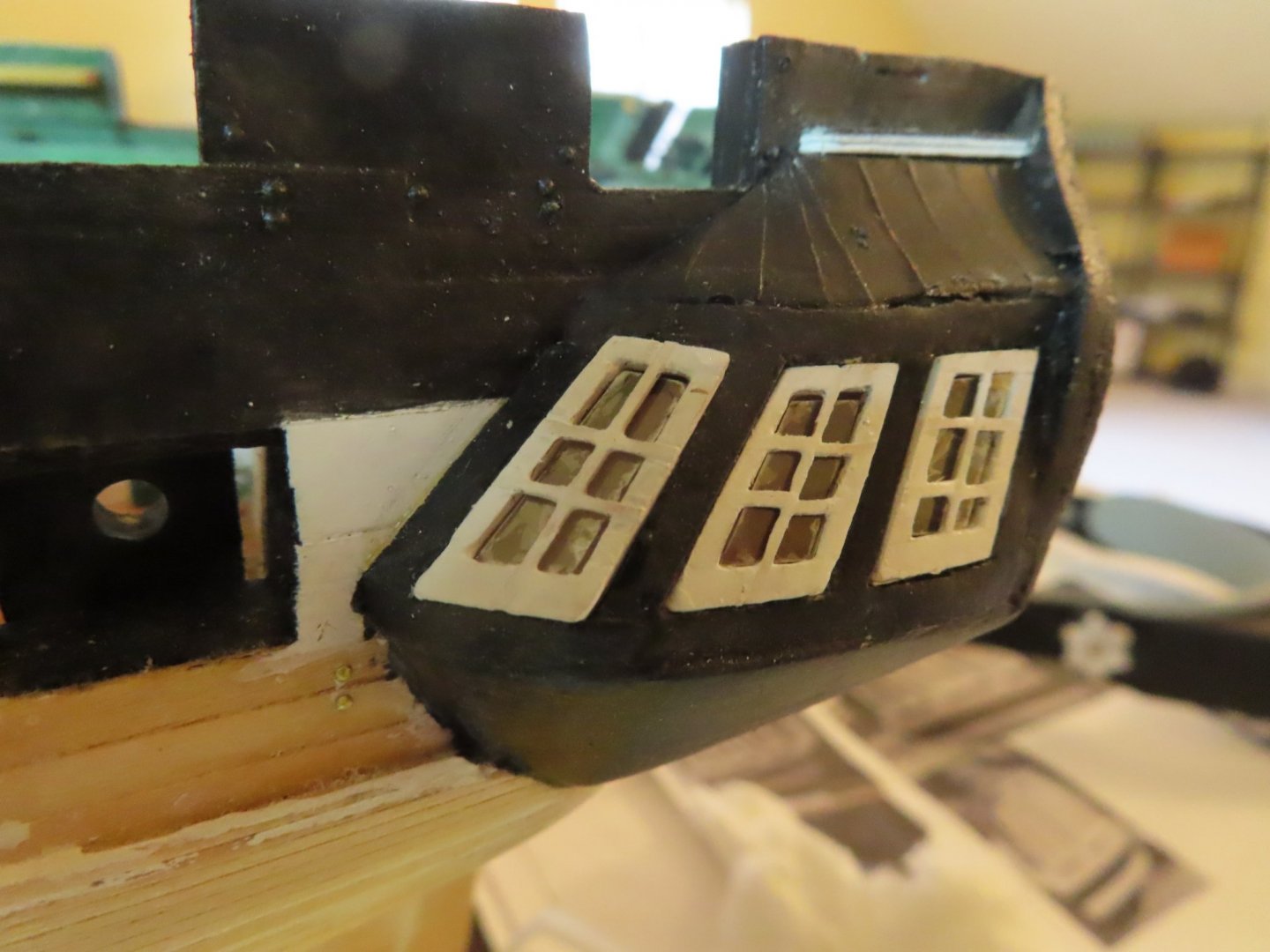
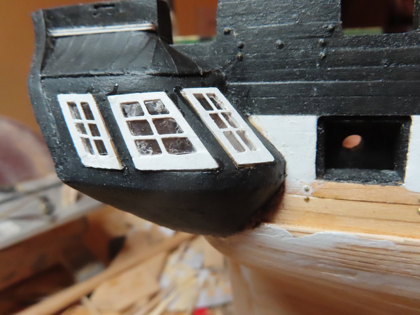
Next, the lower decorative moldings were added to the quarter galleries which no flat surfaces. To make them wrap around the galleries, they had to be bent both horizontally and vertically which was a bit tricky. I’m not proud of the craftmanship, but it’s what I got with the skills I have. It could have been better, and it could have been worst. It’s what I now have. There is still a bunch left to do on the transom, but at least they are on a relatively flat surface.

-
The name plate was glued to the transom on the centerline just below the first decorative molding. A second molding was made for the transom and quarter galleries and applied directly below the name plate and wrapped around to the galleries. (Note, 1st image was taken when model was inverted)

-
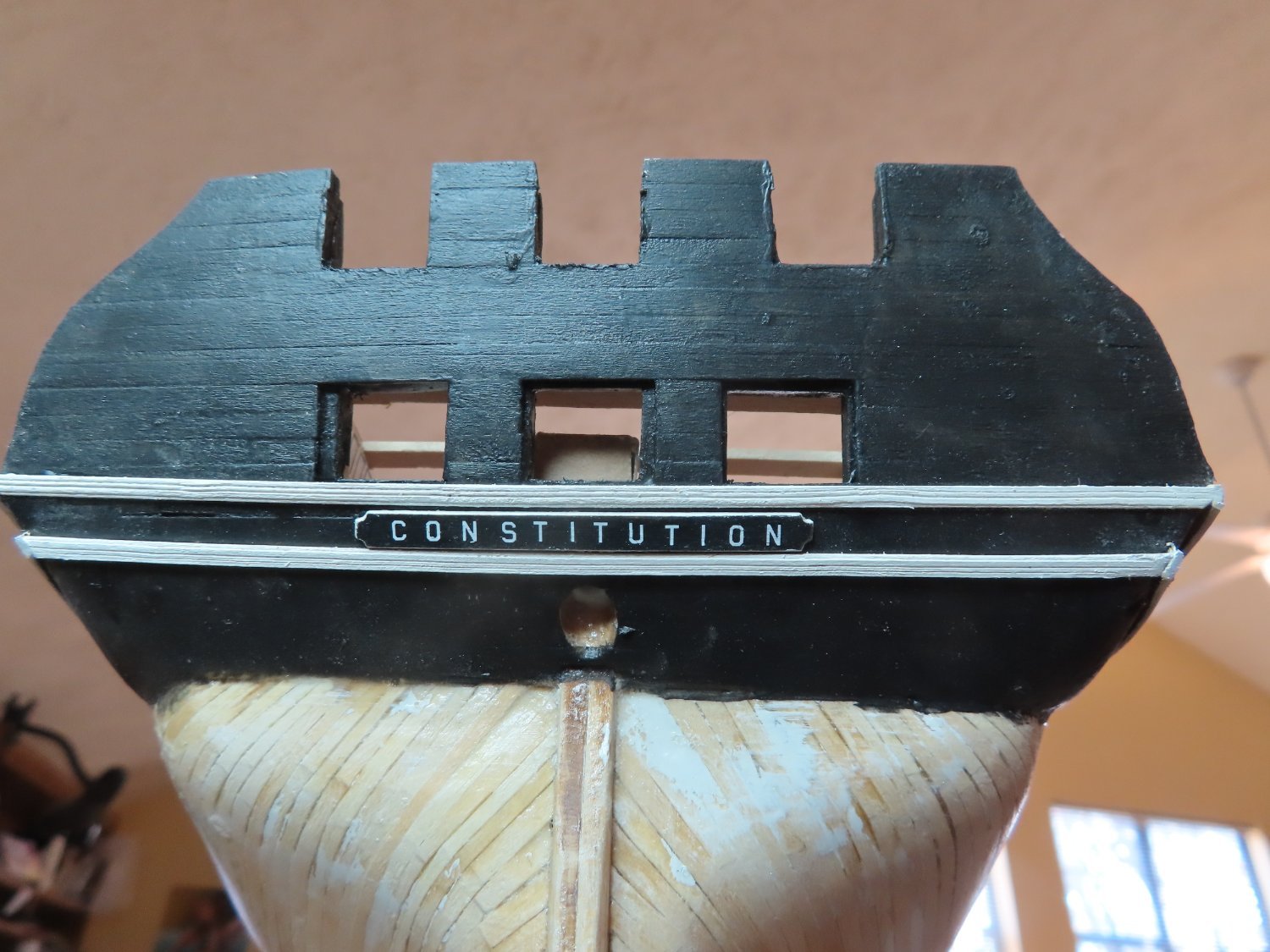
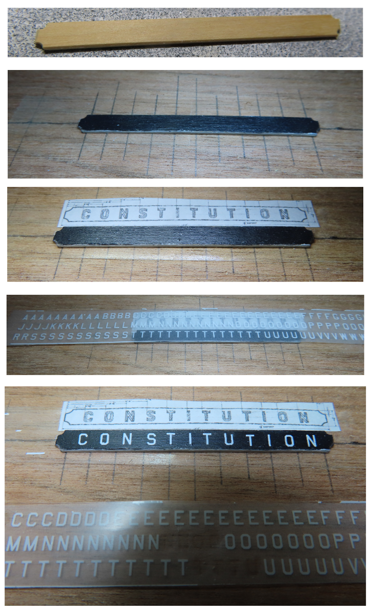
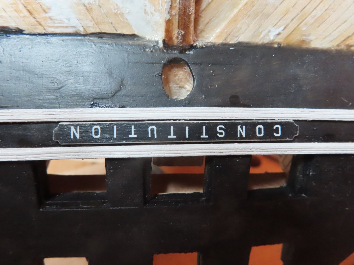
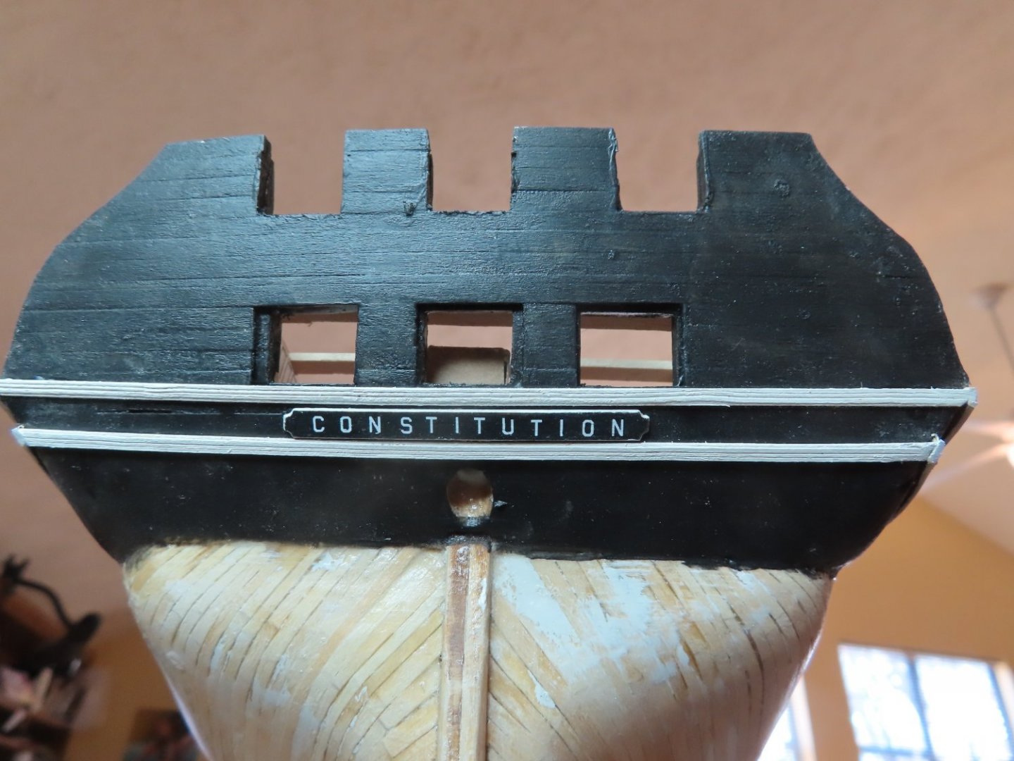
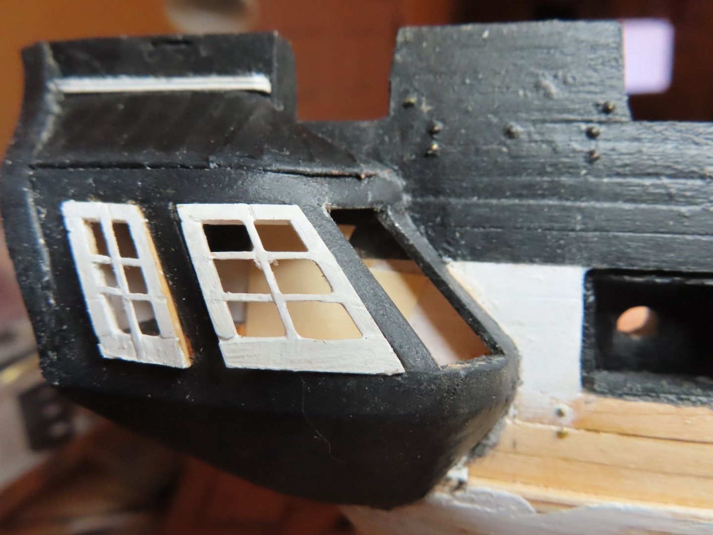
Ship’s Nameplate Separating the lower decorative molding on the transom is the ship’s nameplate. To create this, I used the US Navy plan as my guide. The nameplate shown on the kit’s plans is very close to the Navy plans, but the Navy plans provided the actual dimensions. But like the kit, I had to make compromises due to scale issues. In the end, I used a 1/16” wide x 1/32” thick strip of boxwood cut to the proper length. The corner notches were filed in, and the side were beveled slightly. With a couple coats of paint, the edges were painted white and the face black. Finally, the face was cover with a clear coat of Minwax Polycrylic Protective Finish for a smooth finish. Following the instructions of the practicum, I bought a single sheet, item MG6740, 45° USA Gothic White dry transfers made by Woodland Scenic. This sheet has several different sized white letters and numbers sets. I used the 3/32” set. I bought other different sheets as well which I will discuss when I use them. To transfer the lettering, I drew some guides lines as a visual aid on a piece of wood which was then covered by a length of double sided tape. The blank nameplate and a copy of the name plan (reduced to scale) were then laid on the tape. The plan image acted as my layout guide. All I had to do was burnish the transfer letters onto the nameplate below the corresponding letter on the plan. To make the burnishing a bit easier, I cut the 3/32” set off from the original dry transfer sheet for easier handling. Once all the letters were applied to the name plate, another coat of Polycrylic Protective Finish was applied to protect and seal the dry transfers.

-
The next piece of trim to be added to the quarter galleries was the decorative molding just under the windows. The thing is, the quarter gallery molding must line-up with the transom molding and the molding on the opposite quarter gallery. A length of 3/32” boxwood strip was scraped to create the grooves in the decorative molding. First, the transom molding was installed just below the window/gun port openings Then using that molding as a guide, the quarter galleries’ moldings were installed. Finally, the remaining decorative blocks were added to the quarter galleries. All the decorative boxwood panels, blocks, and moldings were pre-painted prior to installation and touched up later if required.


-
Greetings and salutations, Tony from Sydney Australia! Glad you are enjoying my build log. Whoever said these were the "golden years" didn't realize they get very rusty as we get older (I'm 75). Although I "complain" a bit, I am very grateful that in reality, I am in relative good health. No real pain, tremors, or lack of motor skills. Well, maybe lack of some modelling skills. Hopefully, I've had the last of my back and eye surgeries...at least for a while. I wish you well on your Endeavor. Jon
-
Another month has gone by since my last post. I previously mentioned that I had the first of two scheduled eye surgeries. As it turned out, I needed additional surgery to tweak the first surgery and then I had surgery on my left eye for a total of three operations. Although these were 2 hr. outpatient procedures, it slowed me down more than my usual slow self. BTW, the surgeries were to correct a condition where my lower eyelashes curled in, irritating the eyeballs, which affected my sight. However, some progress has been made to the model, sort of. It’s not to my liking, but I will have to accept it. Adding the trim work to the quarter galleries revealed glaring distortions which I tried to minimize. How successful I was, is for you to judge. The key to my frustrations was of course, I did not have a true plan view or image of the windows. After all my effort, the trim and the windows didn’t align as I would have liked it, but I am moving forward.


-
I DID cut down the bulkhead gun deck to compensate for the additional gun deck planking and yet my mock-up gun was too short as well. I was surprised that your guns were short, but you stated that was because the MS carriages were too short. For you, that should have cancelled each other out - the higher deck and the short carriages. That's odd it didn't. However, since I have to do what you are doing with the carriages, I really appreciate your little jig on how to accomplish this task. I've put this little task off until I do more work on the hull. Jon
-
Since my last posting, I’ve had my first of two eye surgeries, actually on my lower eye lid. Once the outpatient procedure was done, I looked like I had a bout with Mike Tyson. I had quite the shiner on my right eye. My eye is still blood shot, but the swelling has gone down a bunch. Needless to say, it has added another in a long list of excuses why I haven’t made much progress this past week. I did try though. In preparation for the trim work for the quarter galleries, I needed to make some more trim from stock. That meant setting up the Dremel drill to make more scrapers. All I managed to do was break two grinding discs before I even turn on the tool. Realizing I could not see well enough yet to make the trim, I did managed to paint the transom black which had to be done anyways.

-
Just started to follow you. You are moving along very nicely. I also am putting in a gun deck, but my model will reflect what the ship looks like today (minus the tourist accoutrements). I admire anyone who can extrapolate what the ship looked like before photographs and accurate detailed plans. Paintings and old models are nice guides, but as any model builder knows, no two models of the exact same ship (or paintings) are identical. The artist/builder always puts in or leaves out details as he/she feel fit. Even though the US Navy has provided some of the ship's plans, I wish they would provide more. There must be more for the contractors working on the restoration of the ship all these years. Keep up the good work and even though you claim to work slow, I think you will surpass me soon enough. I've been working on my model since Feb 2017. Jon
-
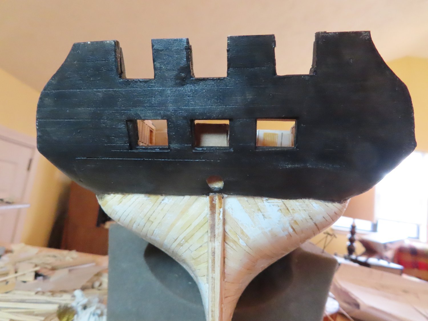
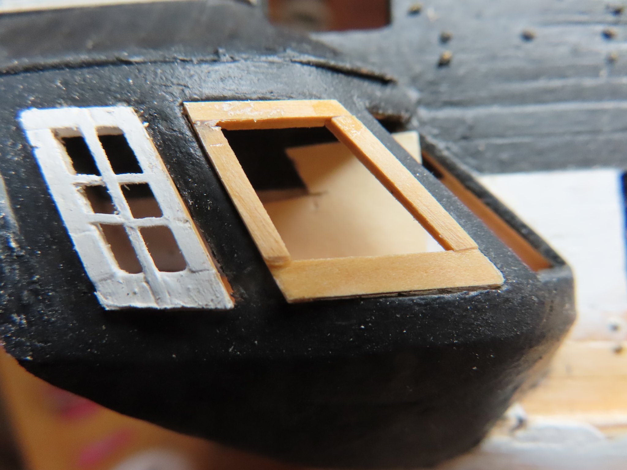
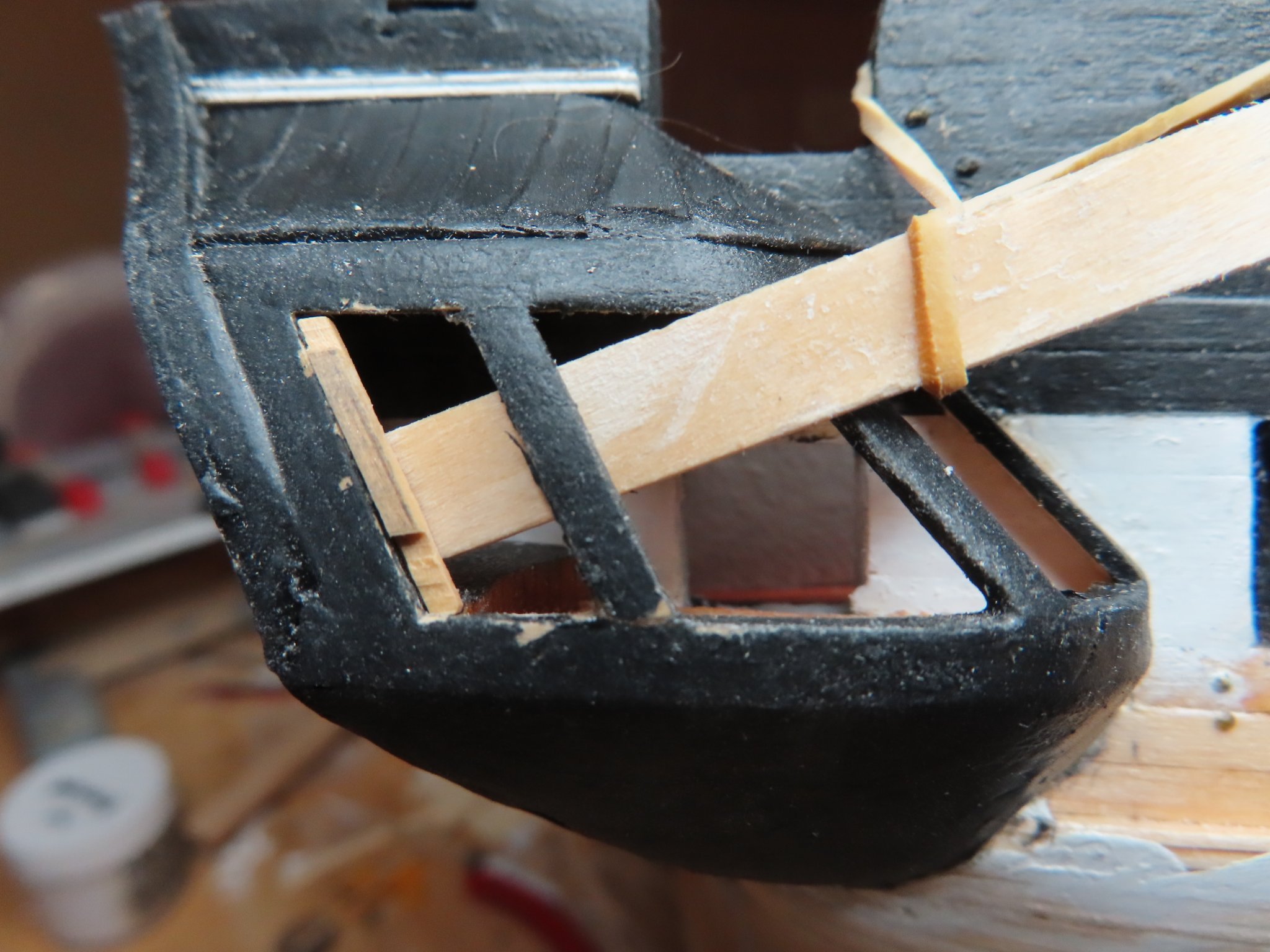
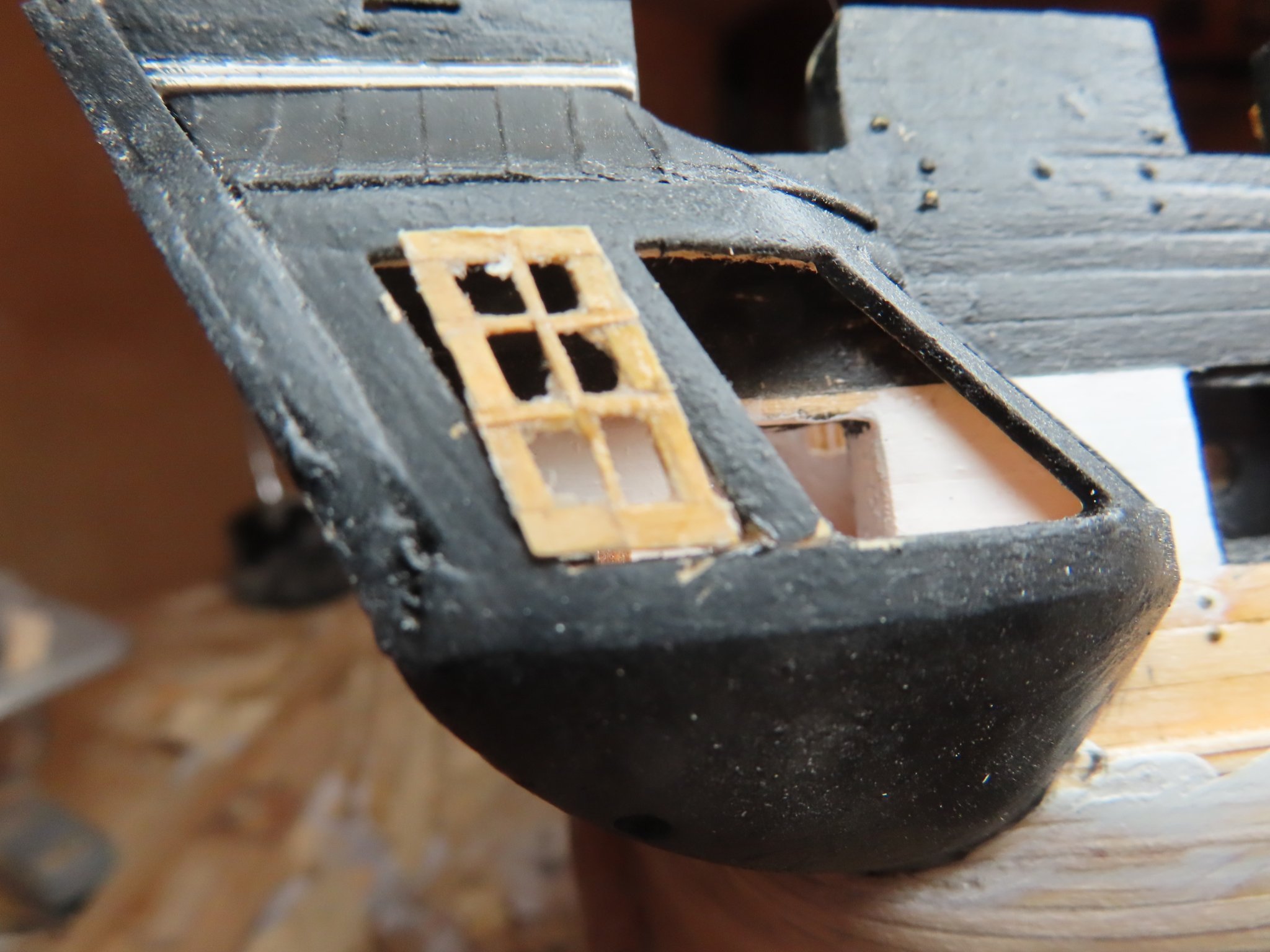
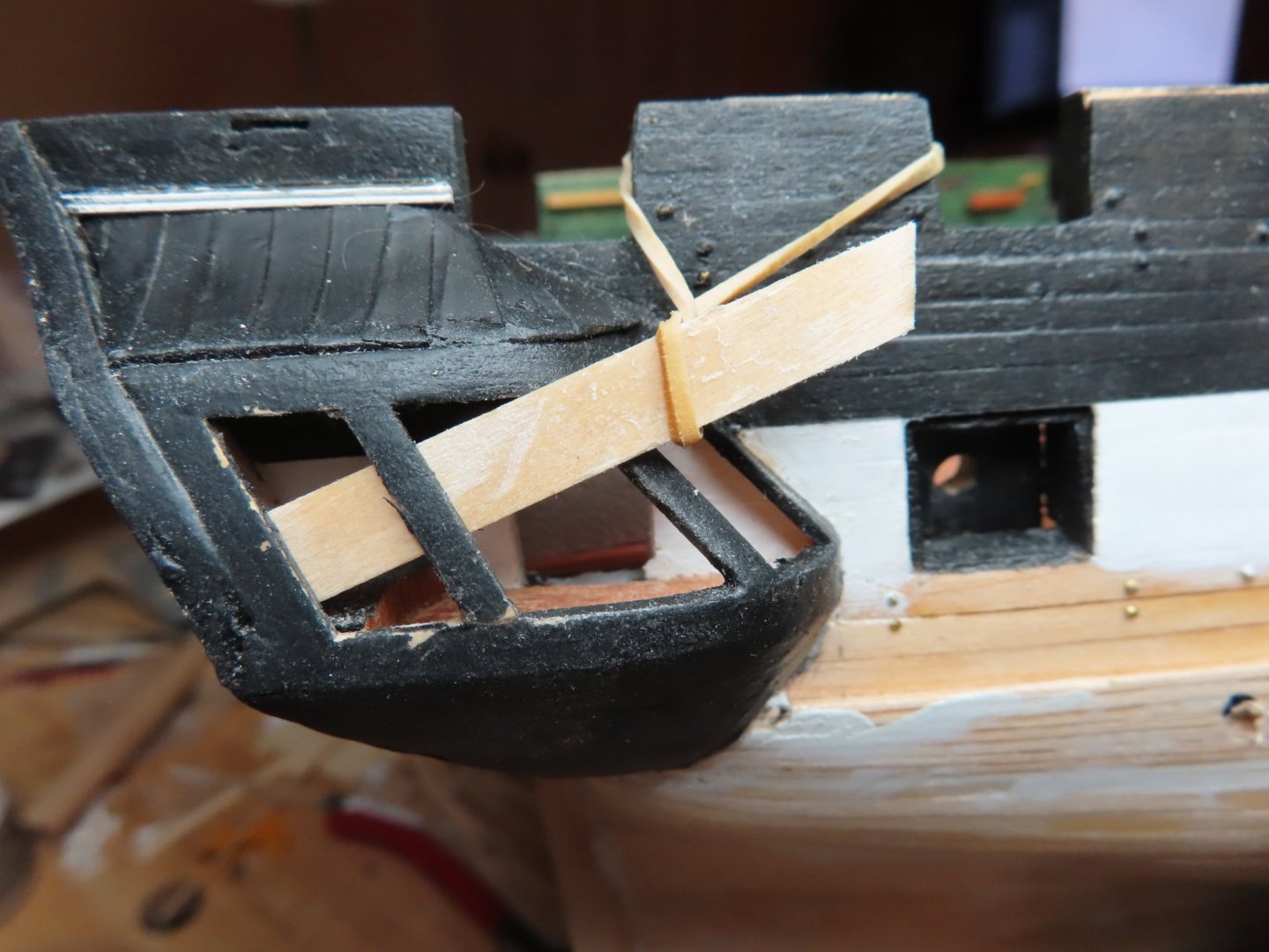
The frames were then inserted and glued into the window openings of the quarter galleries. Simple process, it only took me …breaks out the calculator…60 days.
-
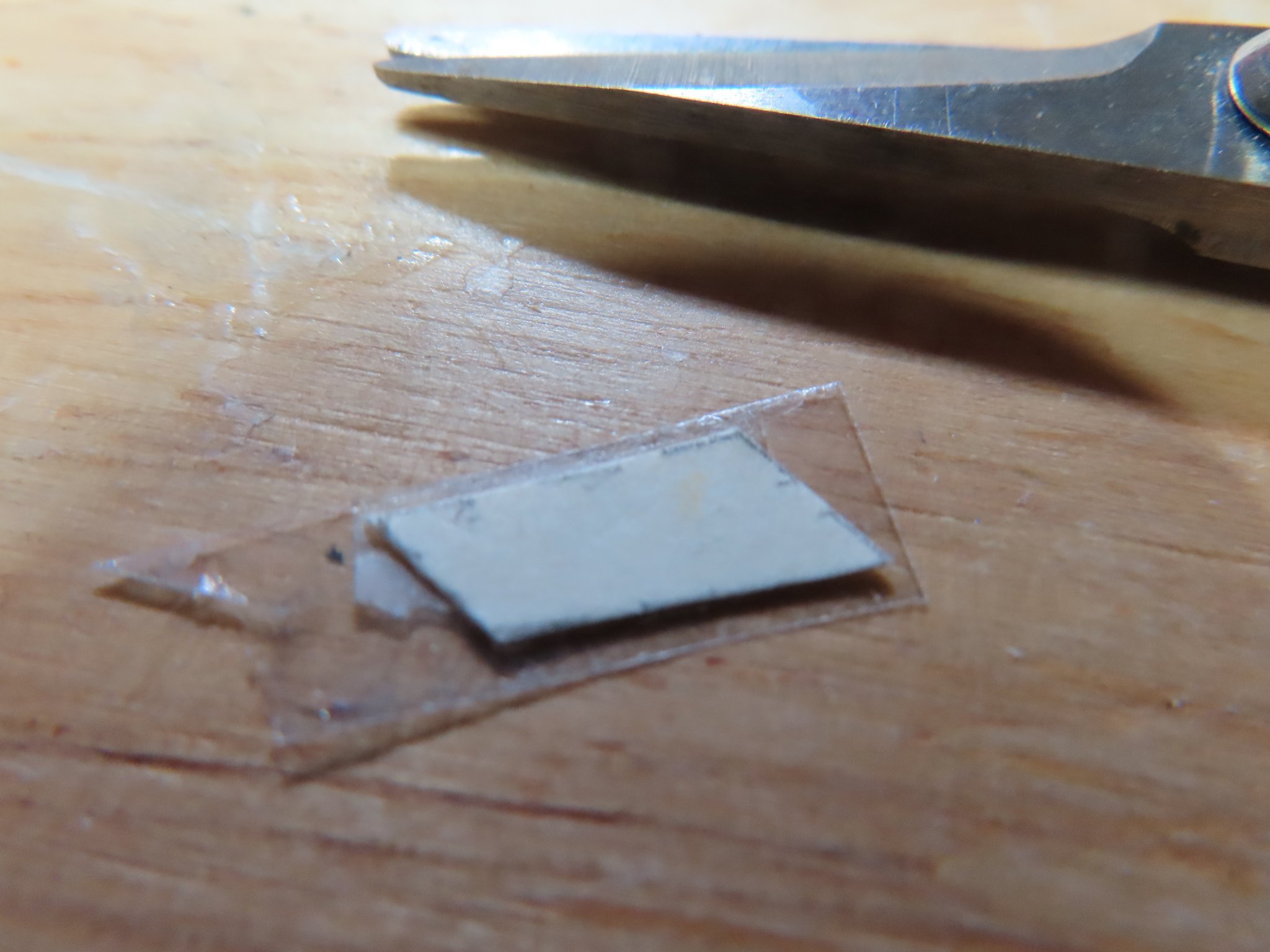
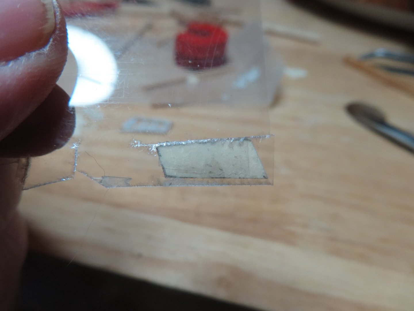
Using just a bit of double-sided tape to secure the template to the mica, the mica was cut to size with scissors and a very sharp X-acto knife. Then the template was pried off with the blade. In most cases, the mica cleaved apart from itself leaving a fine layer still stuck to the tape. The mica was then placed inside the back of the window frame and secured there with a few tiny dabs of PVC glue in the corners of the frame.

-
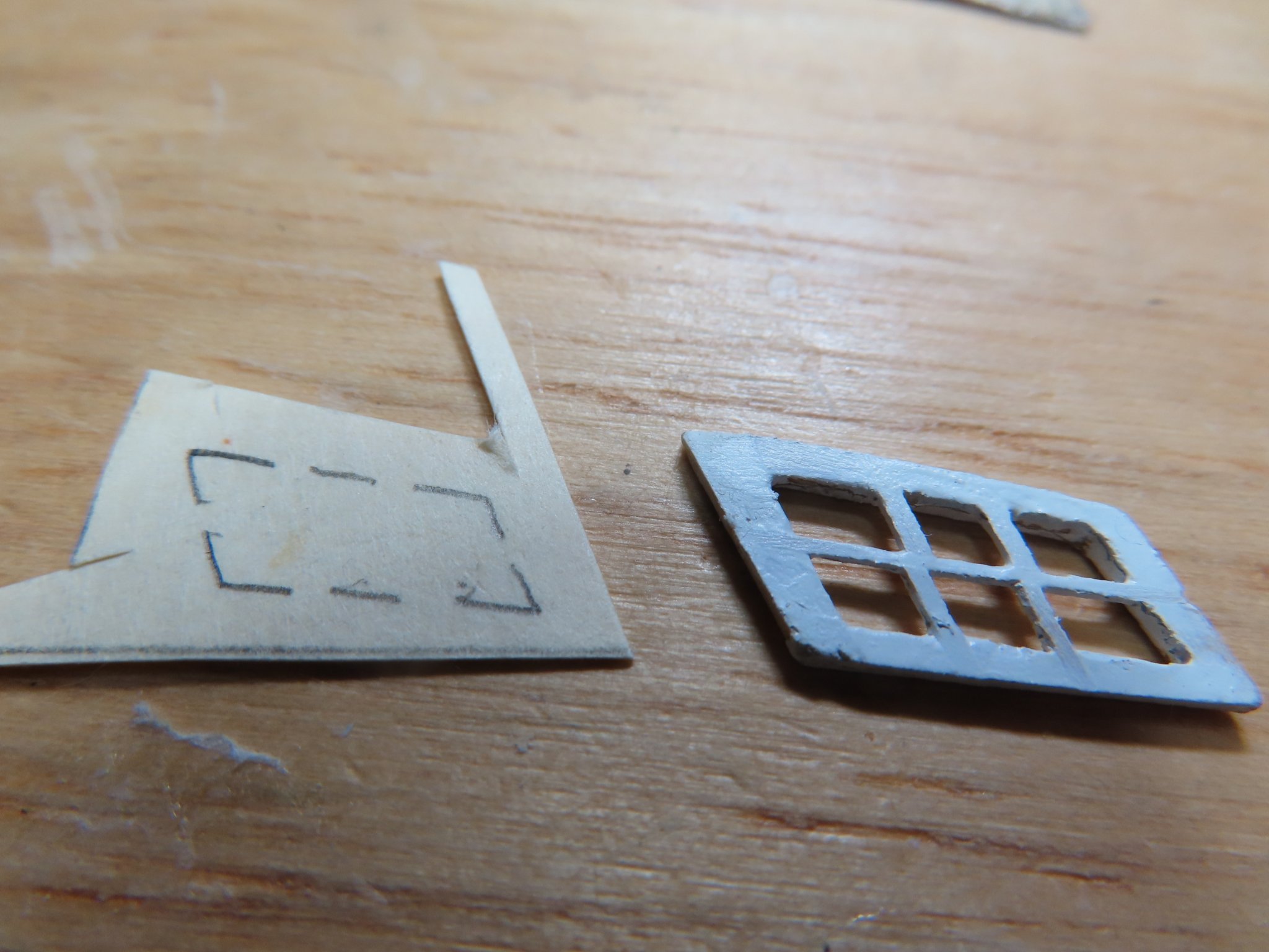
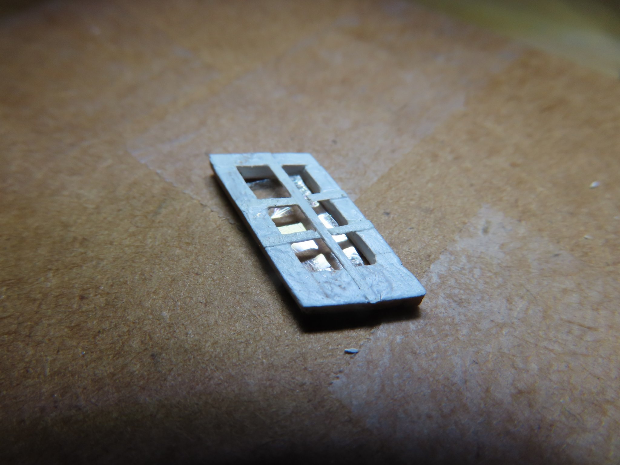
It’s been just over 5 weeks since my last post and like an old-time movie serial, left my readers hanging as to what happened. Well, I had some distractions like Thanksgiving where I took to week trip to visit my sister whom I hadn’t seen in two years due to the pandemic, getting my bathrooms renovated (master bathroom finally done just last week and the guest bathroom this coming week), dealing with my eyes, (I have surgery scheduled for the right eye next week), and overall frustration that I could not get the window sashes made to my liking. After a lot of interruptions as noted above, false starts, do-overs, lost pieces (the rug gets very hungry), clogged CA glue applicators, and other gremlins all well known by model builders world-wide, I finally got all six sash frames completed. Some came out better then others, none was perfect to my standards (which were probable over my skill level). Once the frames were touched up, voids filled, tweaked the frame openings for fit, and painted, individual templates were made from card stock for the mica pane inserts.

-
Well, you've accomplished a lot more than I have. Nicely done.
-
Kirby - Thanks for looking in
-
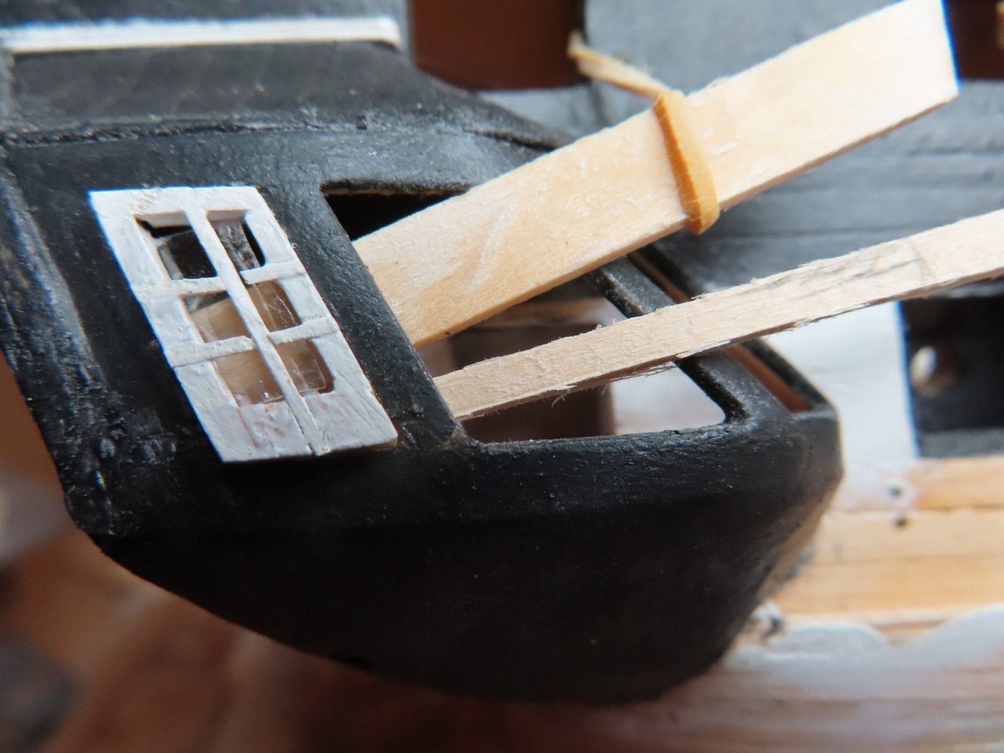
Slowly making progress, but progress, nevertheless. 2nd window, starboard side dry fit, sans mica. From these close-up shots I see that I still have to clean them up a bit.
-
The more I looked at the sash, the more I didn’t like it. So, I started over and made a fourth attempt, using the same method as the third, and although not perfect, the results were more acceptable. So much so, I’ve started on the next sash. The picture below shows the dry fit of the painted, sans mica, fourth attempt as well as my progress on the second sash. The close-up shows waaaaay more flaws than a normal viewing would reveal. Luckily, most people will not see them. The next few days is the week before Thanksgiving, I’ll be preparing my visit to my Sister’s home for the holiday, my bathroom renovation continues, and ophthalmologist notified that I still need some minor surgery on my eyes. The surgery is out-patient, and hopefully won’t hinder me too much on my model. So, if my lightning building pace slows down a bit, I hope you followers will understand.

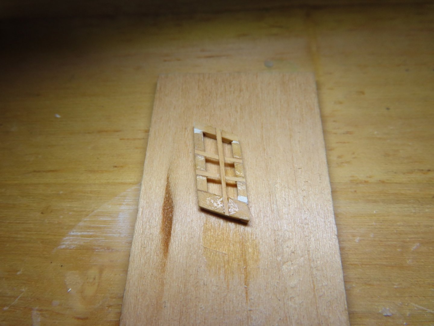
-
The front surface of the frame and all but the back surfaces of the muntins were painted white. Once dry, the frame was flipped over, and a piece of mica was place inside the back of the sash and secured with four dabs of Wellbond at the interior frame corners. The results, to my eyes, were acceptable but not the great. I attribute that to my building skills, not to the method. Although the window fit, the horizontal muntins should have been more parallel with the base of the window opening. I will see how the next window goes. I may go back and do this first window a fourth time.

-
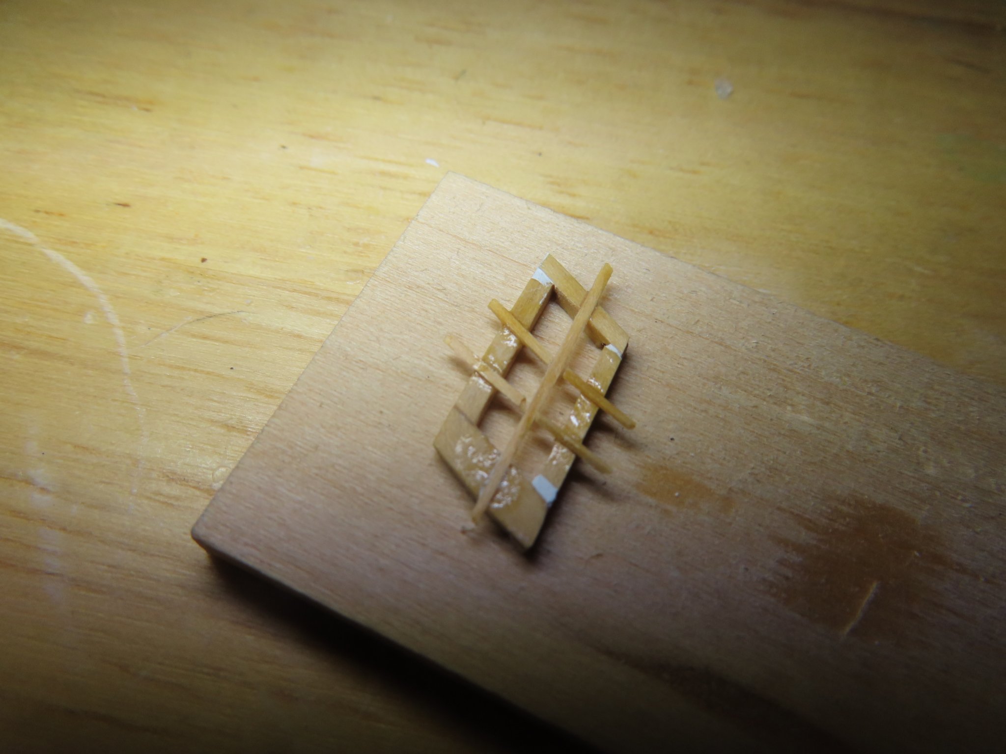
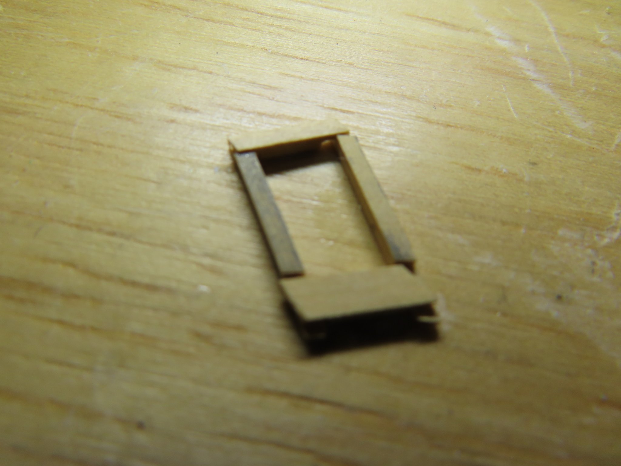
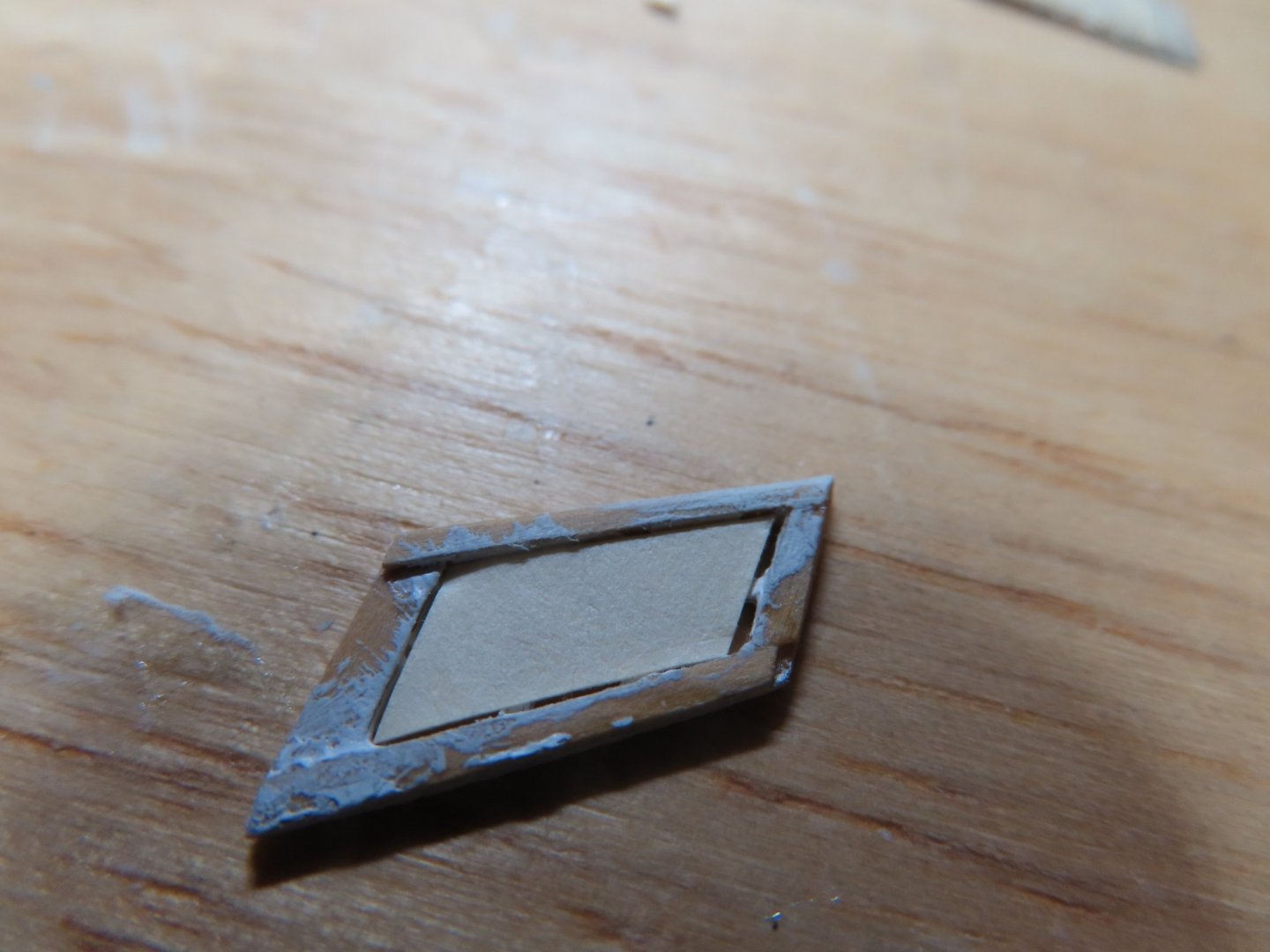
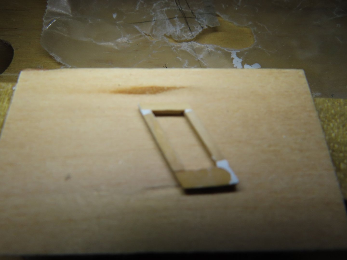
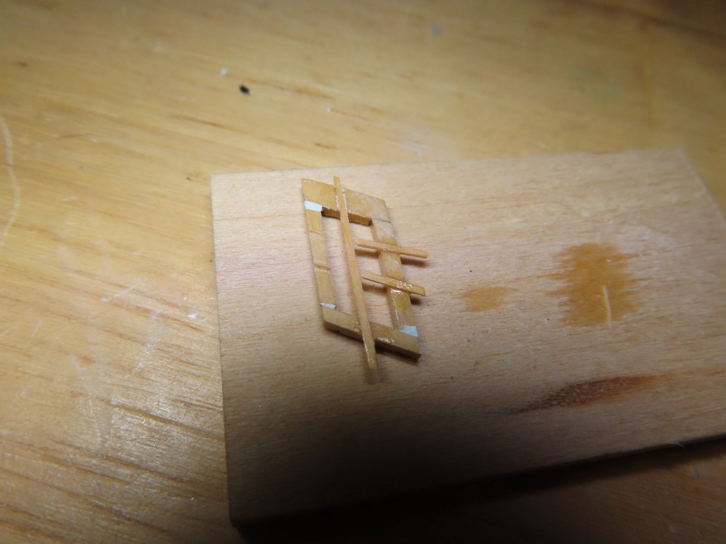
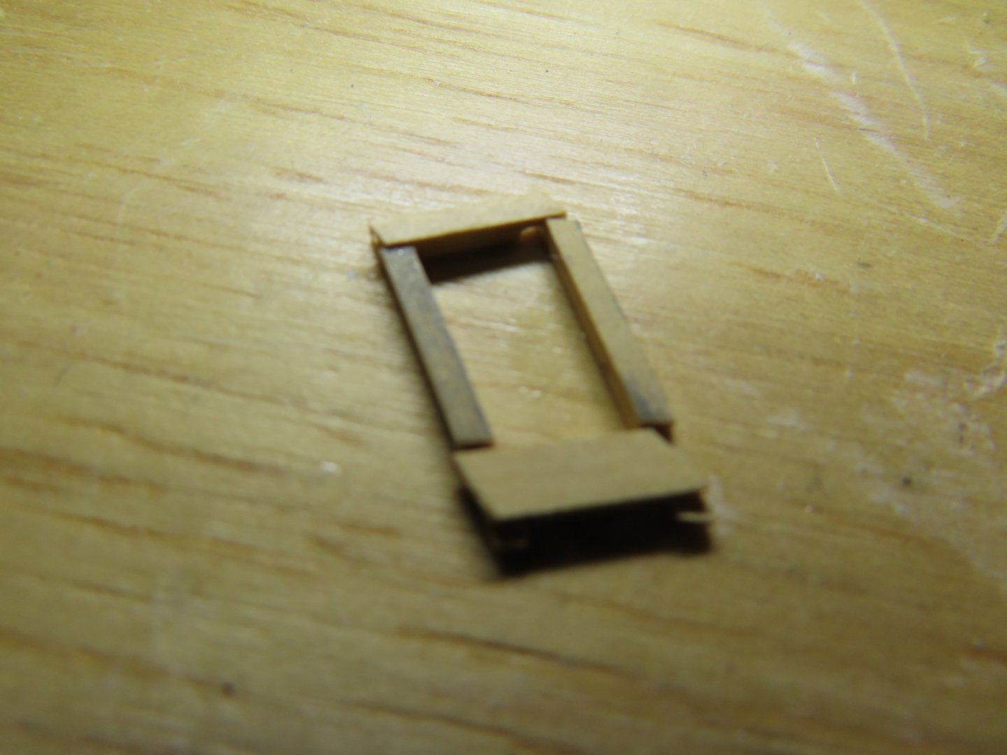
Once the frame was formed and solid, any voids in the frame were filled in (sorry for out of focus image). Next came the window muntins. Using my fine hand miter saw, grooves were cut into the frame, one vertical and two horizontals about 1/64” deep. Because the grooves provide a solid gluing surface, the 1/64” square horizontal muntins met at the vertical muntin and touched. No support at this point was needed. The excess material was removed, and the surfaces sanded very carefully.
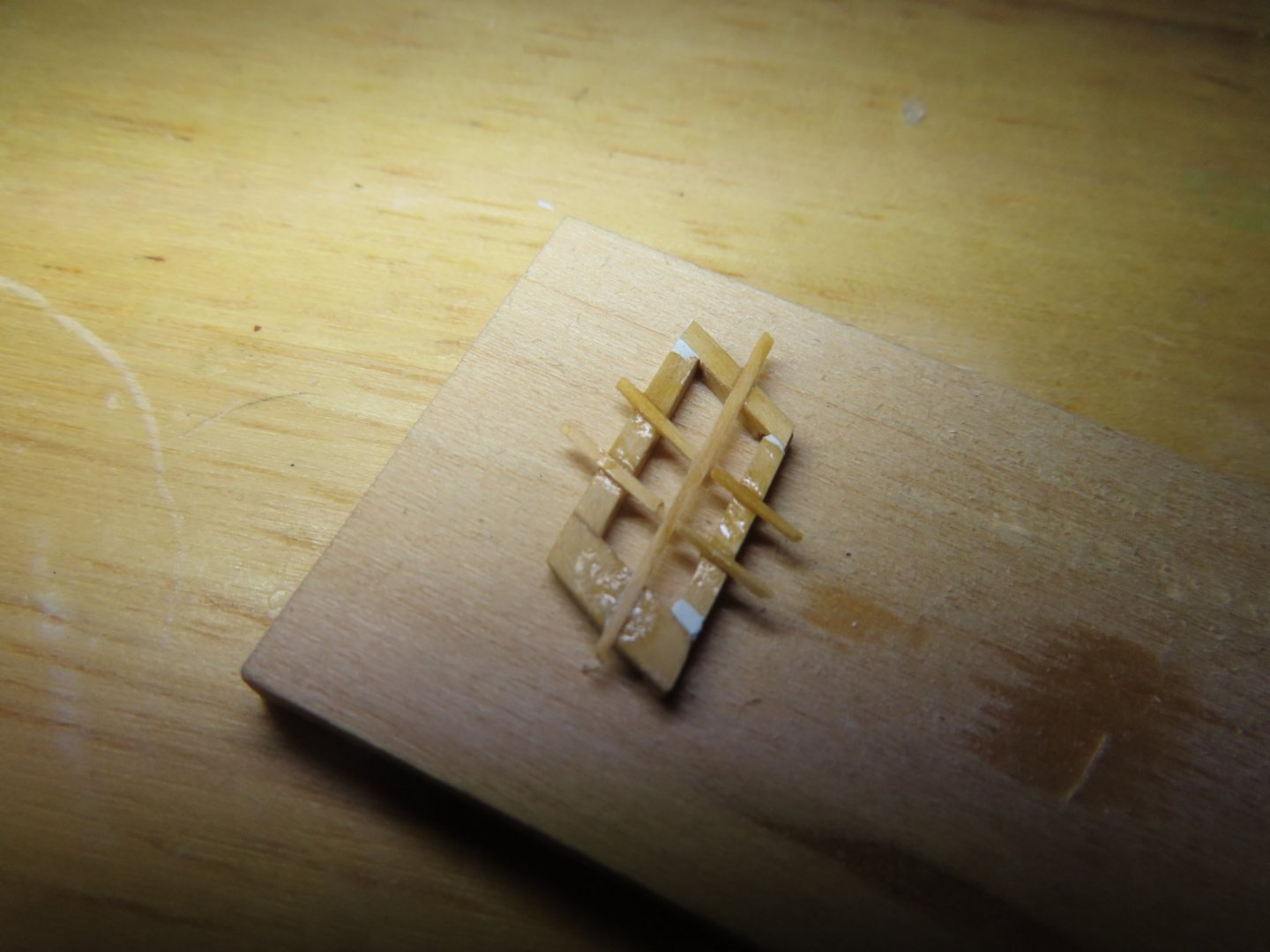
-
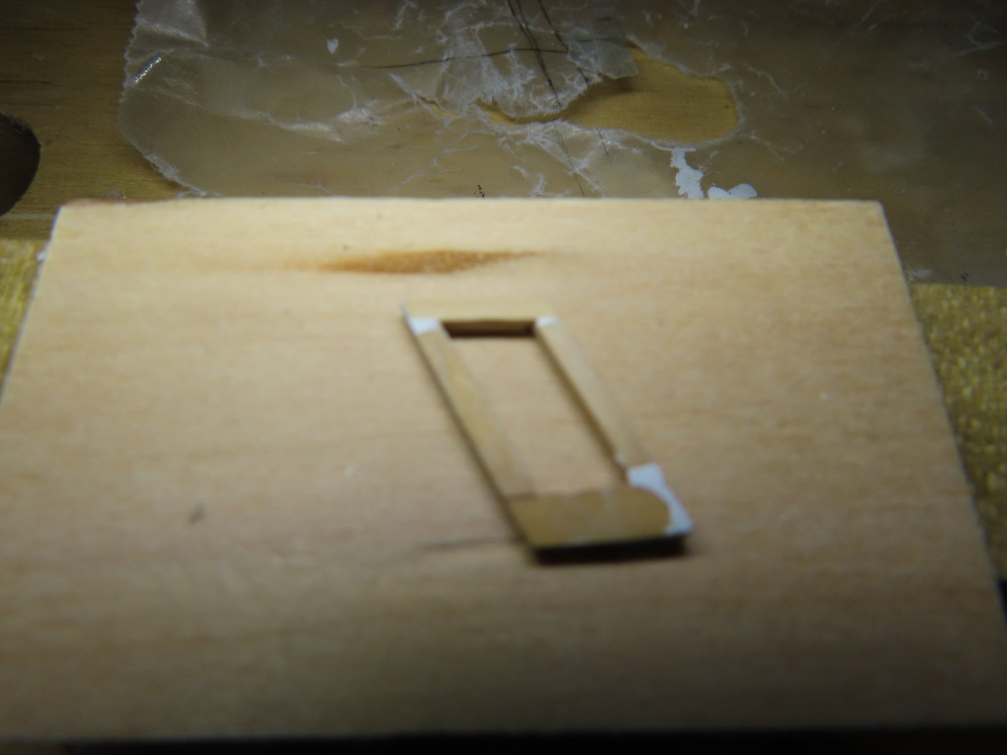
The first corner (in this case the lower left in the image) was glued together with a very small dab of Weldbond glue at the joint. This allowed for final adjustment. Before the joint cured, CA glue was used to get glue into the joint seams. The other three window joints were glued in the same method. The sash was NOT glued to the window opening at this time. Scrap wood was jury-rigged to provide a backing to prevent the pieces from falling into the model.

-
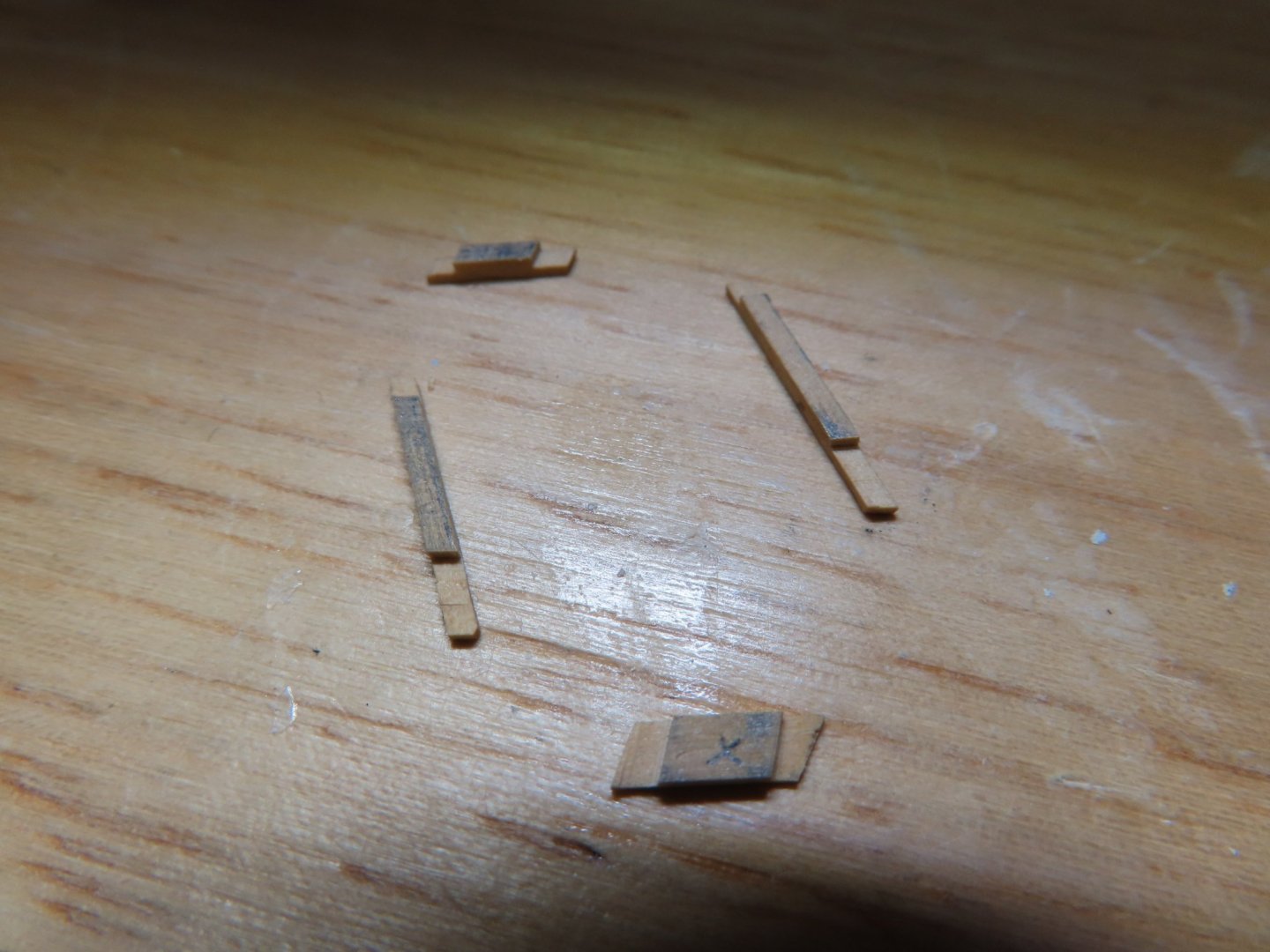
Well, I finally got some work done in between maintaining an eye on my bathroom renovation. Over a dozen people have come in and out of my home and its not over yet. Plan C worked…mostly. To create an accurate window frame, I measured directly from the model’s window opening, skipping making a template. Boxwood stock was place along the window opening and cut and trimmed to fit. Once the four sides pieces were made, a lap joint was made using the Byrnes saw.
-
Well, Plan B failed. I did what I intended, built the sash in reverse and it was easier as I had hoped, but like Plan A, not practical nor accurate. This time the problem was removing the partially constructed sash from the tape without breaking it. I thought I would be able to paint it before the mica was attached and secured with a backing bringing the total thickness to about 1/32”, but when I checked to see if it even fit properly in the window opening, well you can see what I saw in the image below. I hadn’t even cleaned it up, no point. I believe the basic problem is that the component is so small and delicate, any error compounds and magnifies any distortion. I still have at least Plans C (another method), D (jacknastyface2 method*) and E (Practicum’s method). So, its off to Plan C where I will forgo using a template and get my sash shape directly from the window opening. Stay tuned to the next installment of “Crash & Burn or Possibly Survive.” * jacknastyface2 is a fellow model builder on another site