JSGerson
-
Posts
2,642 -
Joined
-
Last visited
Content Type
Profiles
Forums
Gallery
Events
Everything posted by JSGerson
-
 Welcome to the world of model ship building. It's invariable that kit parts are not accurate, not provided, poorly made, etc. As a result, you end up making your own details and gaining skills along the way. Things like blocks, miniature rope, eyebolts, rings, and other rigging items I sometimes purchase from third party suppliers, or if that fails, attempt to make them myself. Knowing what something is suppose to look like is a tremendous help so I have a vast library of images I've accumulated of the years, of nautical details, as well as books, and "how-to" articles I've gleamed from other build logs from which I can follow. There is a lot of stuff on YouTube too. If I were to make the chain plates, I might use thin copper or brass plate, cut into strips. At those thicknesses, a pair of sturdy scissors or a stout knife and rule could do the job. Then punch the necessary holes with an awl, nail, or heavy needle; smooth out the hole edges, and bend to shape. Finally, use some blackening agent on the metal. Paint is too thick and doesn't look right. As for the color of the carriages, they are red not orange. I don't know the official color name but I would call it "redwood furniture" red. The bright sun affects the color in the images. BTW, I'm still learning too.
- 88 replies
-
- 1
-

-
- Constitution
- billing boats
- (and 1 more)
-
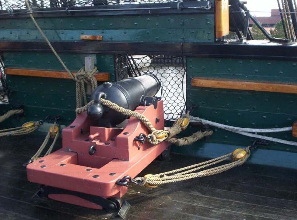
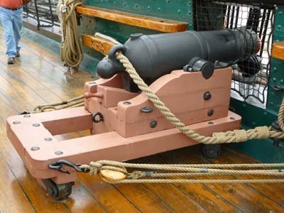
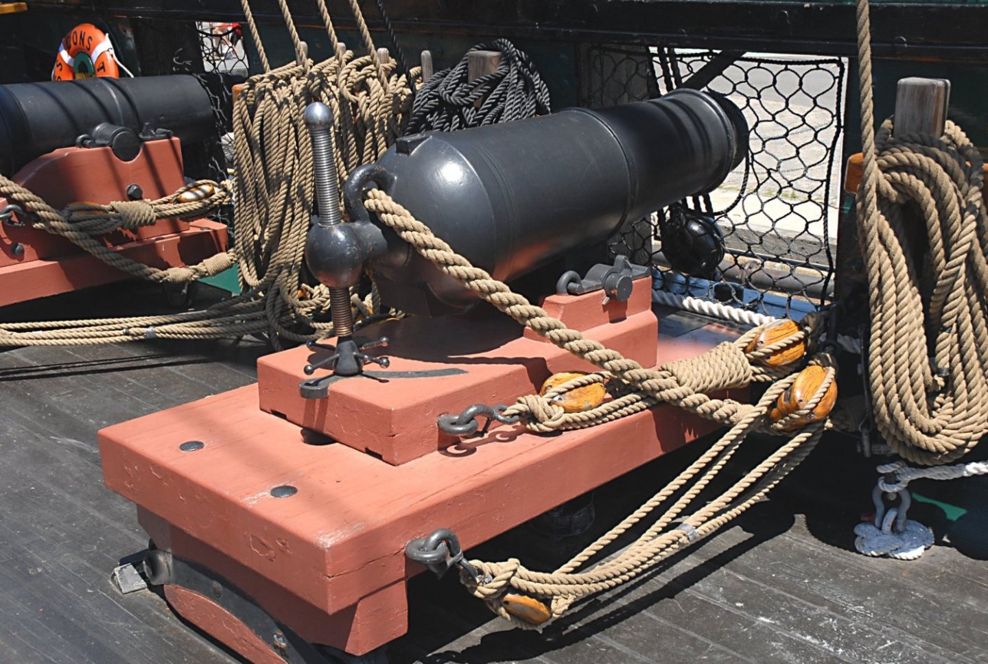
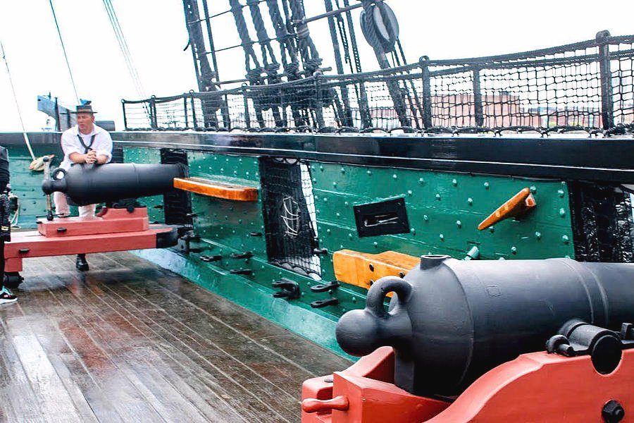
Out of curiosity, what method of adhesive did you use for the stanchions, epoxy or silver solder? How did you hold the pieces in place as you joined them? You stated: "I don’t like the fact that the cannons are not on wheels in my kit..." Technically most (not all) of the guns on the spar deck are cannonades and have a different type of carriage to hold the short barrel gun than the traditional long barrel gun carriage. The back wheels are small and are tucked under the carriage allowing the back end of the carriage to move side to side. There are no front wheels as the carriage rests on a pivot pin so the gun can be swung left and right. Presently, there are two types of replica cannonades on the actual ship today. The one with the vertical angle adjustment screw is more accurate than the more abundant gun with wedge adjustment. The images I've provided show the rigging. A lot of modelers elect not to include a lot of the gun rigging due to scale.
- 88 replies
-
- 3
-
-
- Constitution
- billing boats
- (and 1 more)
-
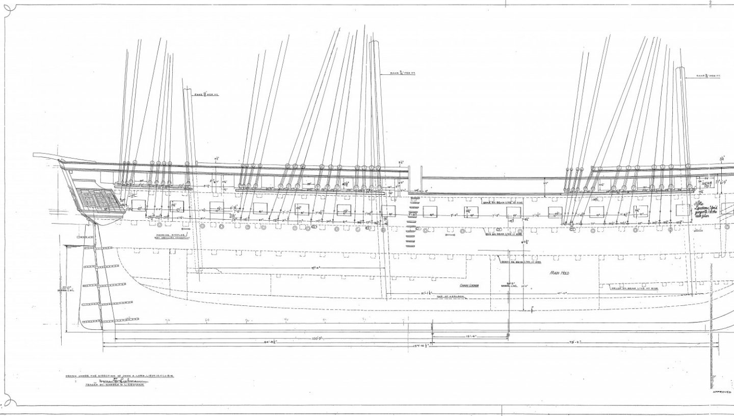
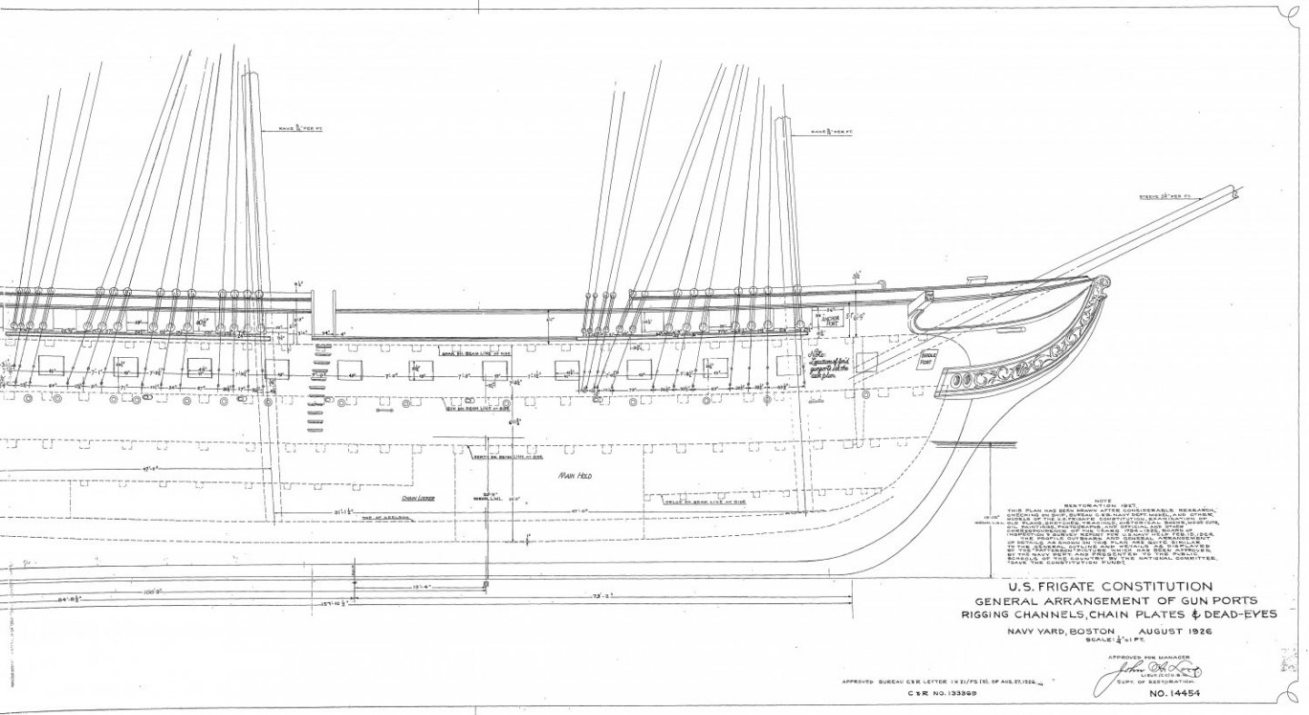
I have no idea if your measurements are correct but hopefully these plans from the US Navy (which are available at the USS Constitution Museum website) will help. Jon
-
If you go to the USS Constitution Museum site, you will find a lot of US Plans of the ship. I found one that may help you with the bow bumkins. Jon 25175 - Deck Framing Forward of Stern and Fore Tack Bumpkin.pdf
- 88 replies
-
- 1
-
-
- Constitution
- billing boats
- (and 1 more)
-
I decided to take the "easy" route and make my model based on the 2015-17 restoration. I say "easy" because of all the photographs that have been taken and accessible through the internet. Most builders who choose to create a historical version have to rely on contemporary paintings and models (e.g., 1812 Issacs Hull Model). Most often they choose the 1812 version. I need to see what I am modeling, so I'm making the contemporary version. The Model Shipways kit is based on the 1927-31 restoration. So, the obvious thing I had to do was remove the Top Gallant rail and add the waist. The 2015-17 restoration also removed the bow rail. Of course I won't be adding any tourist enhancements (gun port nets, speakers, etc.). BTW, silver soldering is done with a small torch as opposed to an iron. You can see how it's done on You Tube. Usually the videos are posted by jewelry makers, but the process is the same. My Conny is the first time I ever did silver soldering. Jon
- 88 replies
-
- 2
-
-
- Constitution
- billing boats
- (and 1 more)
-
I've got a long way to go before I get to the stanchions (cages) so my thoughts are conjecture . All of the methods I've seen used silver solder (which I plan on using), which isn't too difficult...relatively. The solder sets quickly, and can be removed to start over if needed. However, the only other method I can think of is epoxy. Like solder, it will require removing excess joint material, shaping the joints, and in the case of epoxy, painting the epoxy joints to match the brass work. I don't think this method is any easier; more likely be harder. Don't know if this helps, but it's all I got. Jon
- 88 replies
-
- 1
-
-
- Constitution
- billing boats
- (and 1 more)
-
My philosophy on details and accuracy is simple. I like detail where the closer you look; the more detail is revealed. What most of us are making are models, not accurate miniature reproductions. Things like tree nails that I added on my Rattlesnake hull and deck, I did not accentuate their presence by increasing their contrast so you could see them better. From a foot away, the casual observer would not see them. Get closer, the detail reveals itself. On the real ship they blend in with the background wood. I got the detail and some of the accuracy. On my Constitution there is no point for tree nails, the scale is too small and everything is painted. I am copper plating the Constitution’s hull with individual copper plates, but I total ignored the copper plate nail pattern found on the actual ship. The detail is too small for the scale, but I tried to give the impression of nails in the plate. I embossed the plates with rough sandpaper, so the plates are not shiny mirror smooth and give the impression it is covered with copper nails. Sometimes I do add detail that the typical viewer would not see (“for God’s eye”) because it was just fun to do, I try to balance the effort of creating that detail versus the chances of actually seeing it on the model. If it’s “easy and fun” to do I might add it. If it is difficult, probably not. I provided enough detail (hopefully) but not all on the gun deck furniture so that when viewed through the (planed) selected opened planks of the spar deck, the observer will get a sense of what it looks like below decks. The builder is the master of his model world. If it pleases him (her), then it’s good enough.
- 163 replies
-
- 1
-
-
- Model Shipways
- Constitution
- (and 2 more)
-
Brian, I have personally collected over the past 10 years approximately 19,000 images (organized in my particular manner) of the USS Constitution, from a variety of sources, covering most of her photographic history. I'm still building my model, so I am still collecting. Should you or anyone else need images of a particular view, angle, item, etc. of the USS Constitution, there is a good chance I may have something to help you.
-
Very nicely done! I suspect of all of the attributes you listed, ... ..."salty seaman's language" was probably the easiest to learn 😁
-
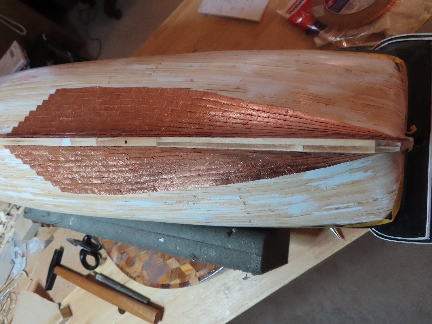
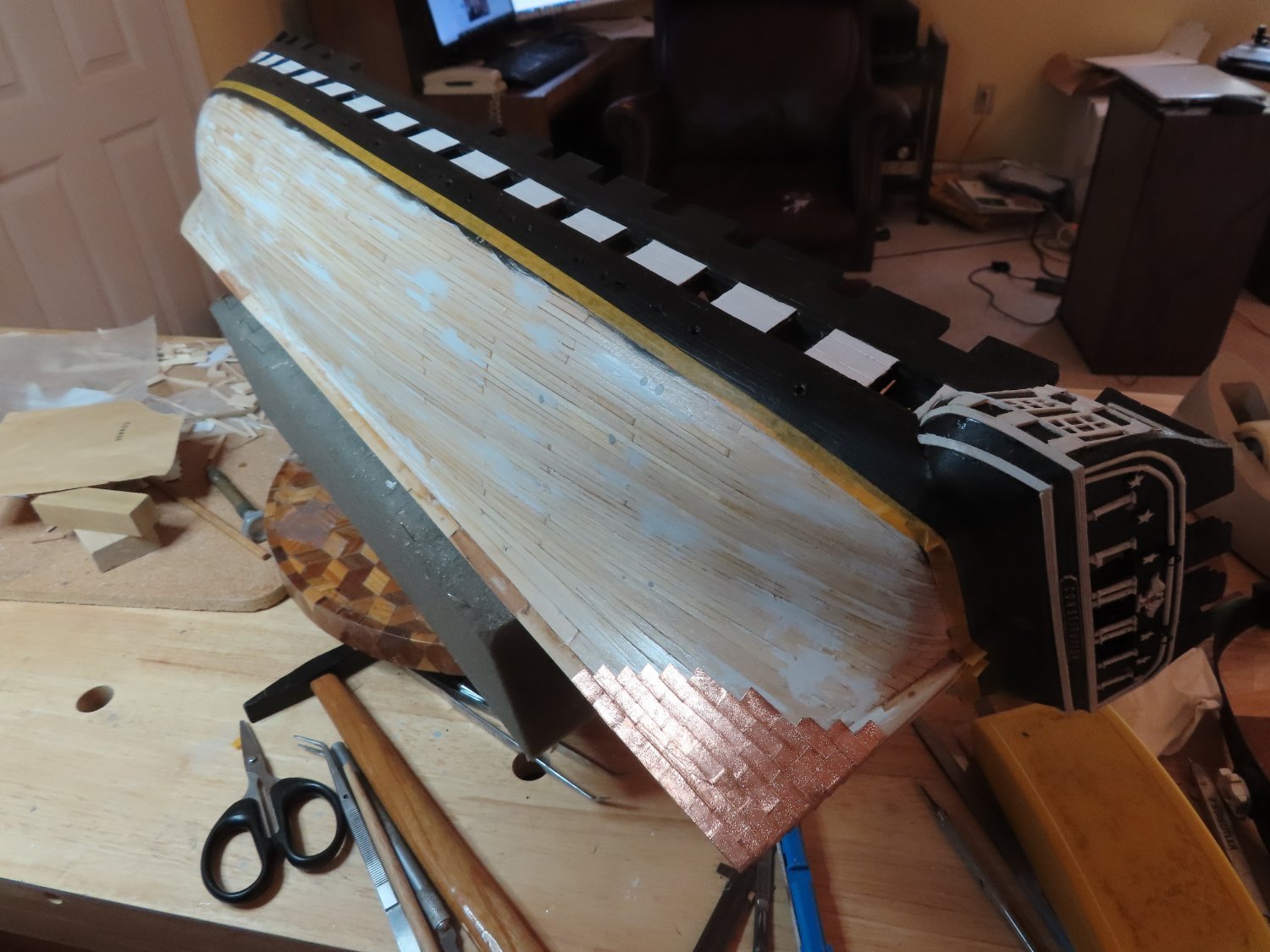
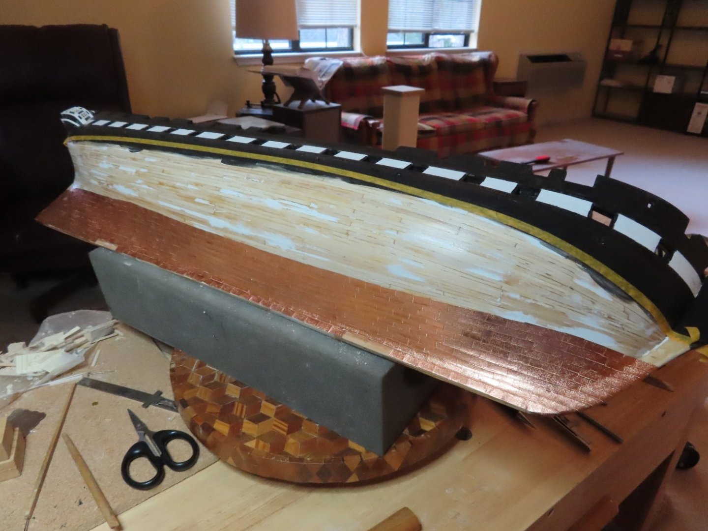
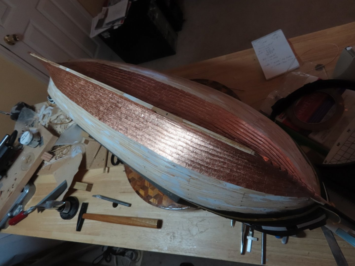
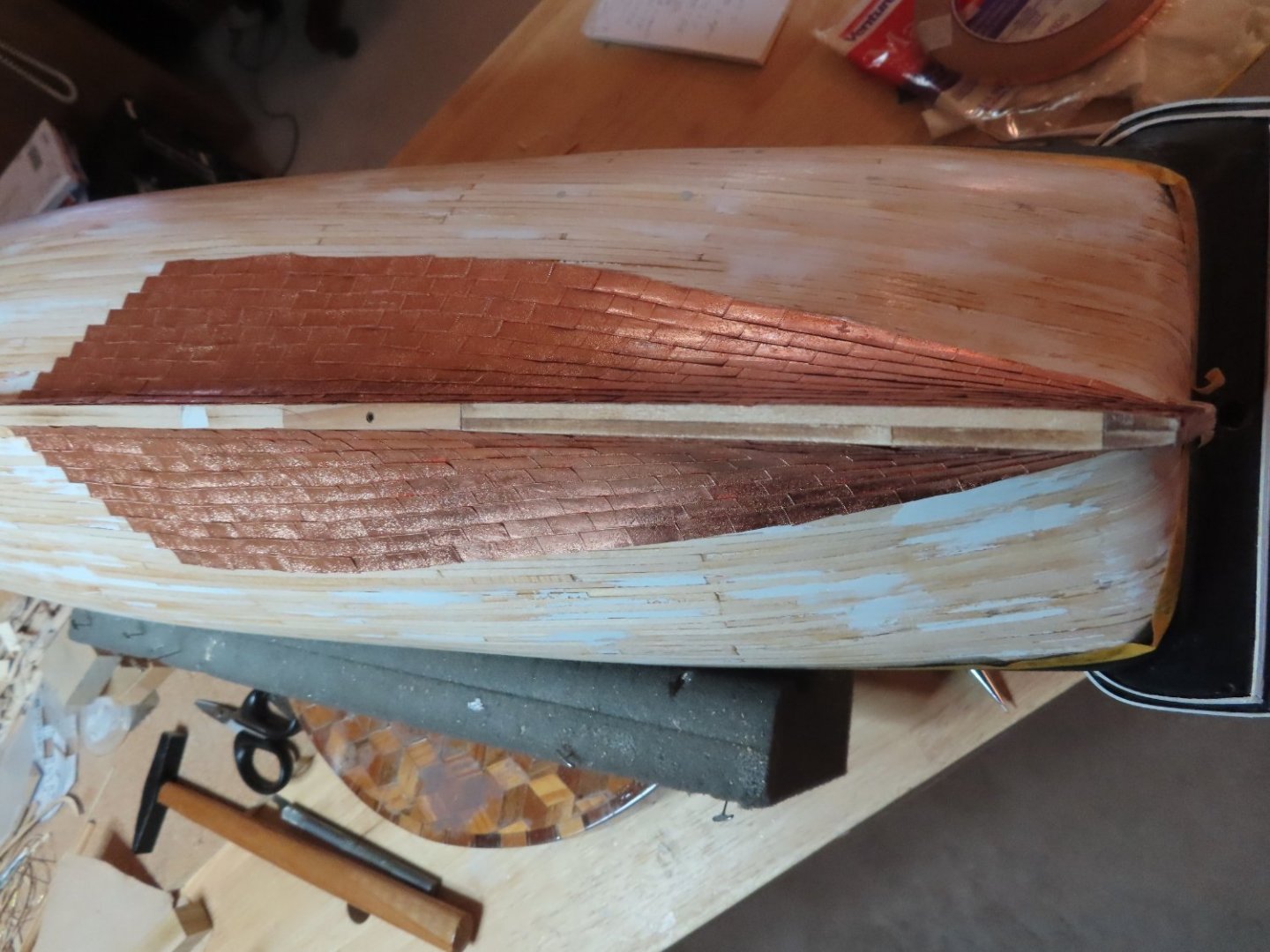
Progress report on the copper plating: I believe I am approaching the halfway point, if not already on it. If you look closely, you may notice two areas of the keel where the sides are not covered in copper. I left those aeras untouched so it can be identified as the places I used wood from the actual ship. Also, I have not yet plated the bottom of the keel.

-
Thanks for the images Avi, If you (or anyone else) is looking for a picture of a particular detail, just PM me; I might have it as I have collected thousands of pictures over the years for my build.
-
Avi, I already tried that. See May 23, Post #159
-
I queried Model Ship World to see if there was some sort of a Photo Reference Library and if not, why not. They said there wasn't: So the best place to post any of your images is your own build log. I hope you do." Jon
-
Has anyone started a photo library of reference material for specific ships, say USS Constitution for example. I've got thousands of images I use as reference material for the Constitution that I gathered from the internet as well as pictures I shot. Some of us would like to share photos we've gathered and pool them into categorized and organized library of sorts but outside of a specific builder's build log. If so, where is it. If not, why not?
-
Avi, up until the late 70s, I lived in the suburbs of Boston and enjoyed a lot of the amenities of the city, among them visiting the USS Constitution. I got one last in person look at her just before her last restoration. I have amassed a large library of images of the ship which I'm willing to and have shared with others for the asking, but I am always looking for new images, different angles, those little gems of details that help me with my model. Unfortunately, I don't have a lot of images of her since the 2015-17 restoration. Would you be willing to post your pictures so the rest of us can enjoy them too? Jon
-
Progress as of May 10, 2022
-
A week or so into copper plating and all is going slow (my usual pace) with decent results. I did run into one annoying problem – the plating wants to lift up even after multiple burnishing. I burnish by rolling a short 3/8” diameter wooden dowel over the copper tape. I want to flatten the embossing, not rub it out. With carefully applied CA glue under the plates that lift, I gotten most of them to stay down. So it’s two steps forward and one back. The pictures below show only one side although both sides are being plated at the same rate.


-
Your Conny is looking good. Sounds like your surgery was successful. I know exactly what you are going through with your back. I had back surgery in 2019. Eight hours on the table, and numerous screws and pins later, I feel better. I have some loss of flexibility due to the lower back vertebrates being fused, but for the most part, I'm pain free. This was my second surgery, the first one was 40 years earlier. If this one is half as good as the first, I'll be very happy. I hope yours lasts a long time too.
-
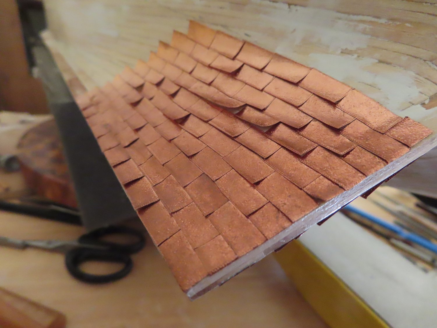
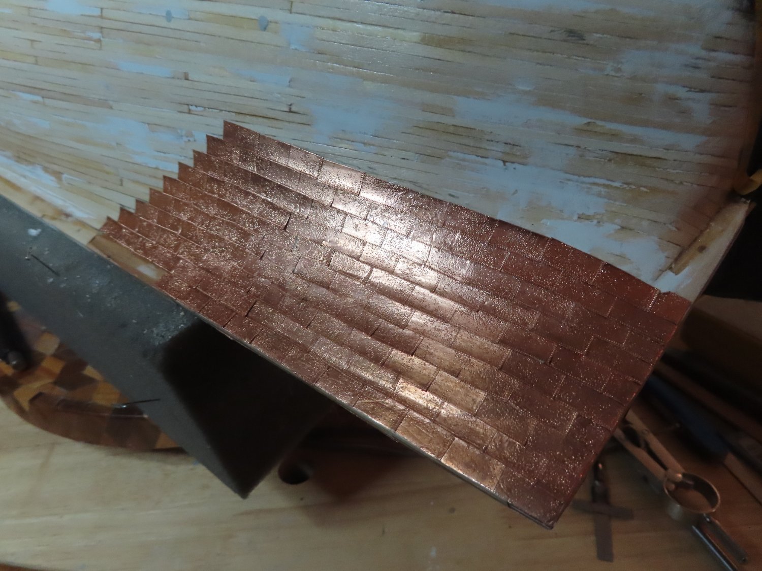
A couple of images to show the initial start of the hull coppering. It’s a slow tedious process, Couple of hours a day is all I can take: cut a bunch of plates, emboss, then apply each plate, repeat.


-
I hope you got my PM with the file you requested. I have another file for the shield on the trailboard. It will be a while before I get to that point as I've started to copper plate the hull first. BTW, those are not gun ports opening on either side of the rudder. They lead into the berth deck steering mechanism space, although I haven't been able to identify the opening from any inside photos I've found. My guess the openings are used for ventilation and for emergency steering ropes that could be attach to the rudder if need be.
-
Your Conny is coming along nicely. You might want to look at how I made my nameplate (see post #611). It's similar to the way you plan to do yours.
-
I remember this method now! It's a very ingenious and it makes for a fast process. Although your log was short, I was impressed when followed your build. I'm kind of machoistic in doing some things the hard way. My method is time consuming, detailed, and prone to missteps, but I think I'll like the results a bit better. Thank for reminding me. I have some ideas that your method has inspired to streamline my process.
-
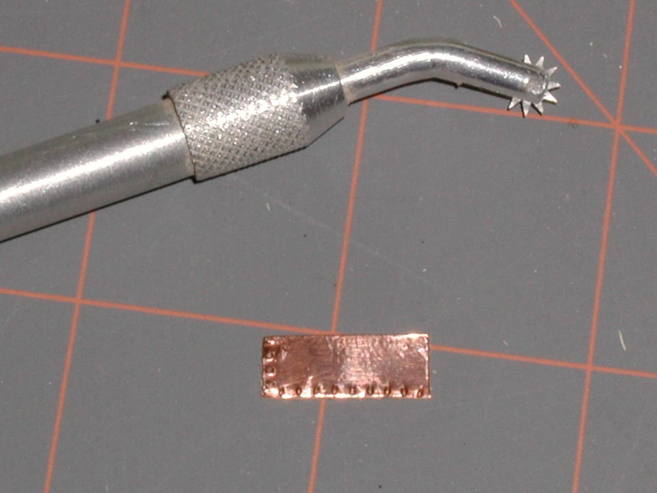
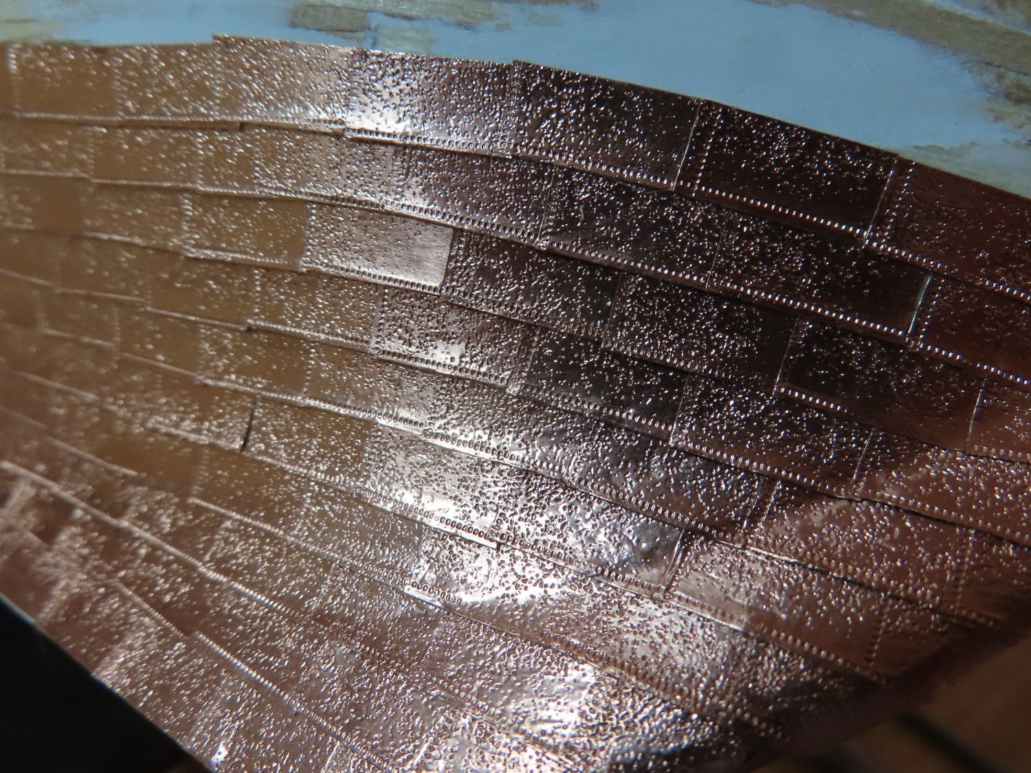
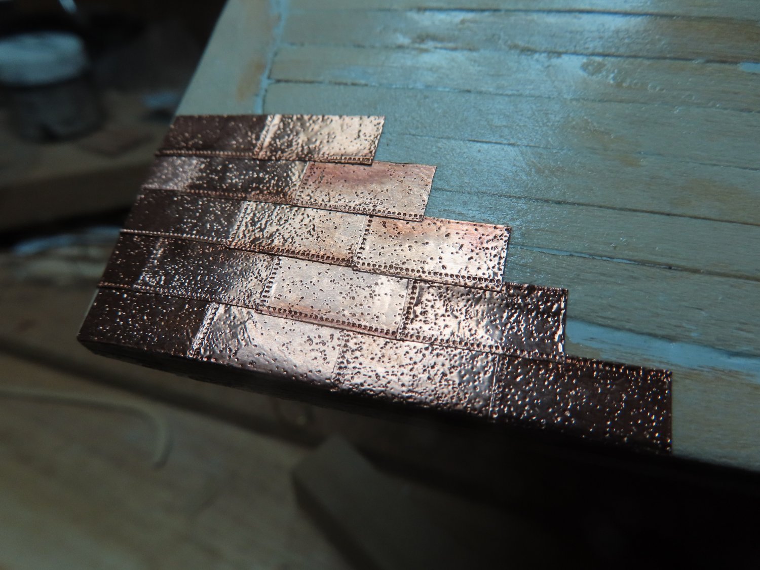
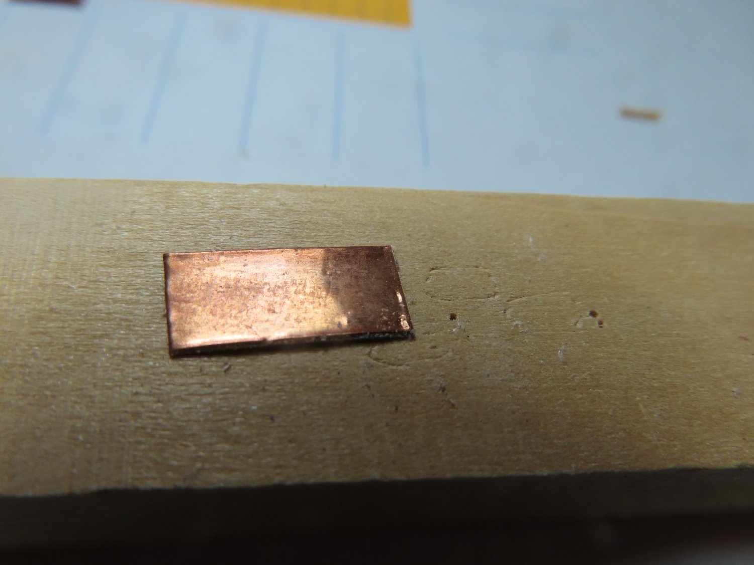
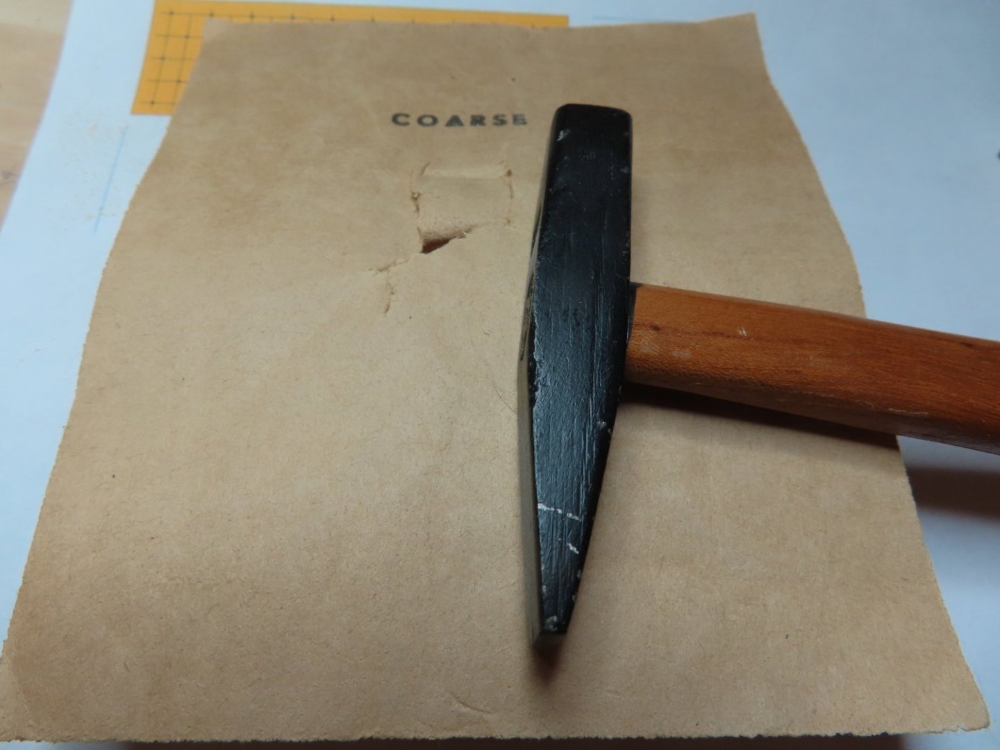
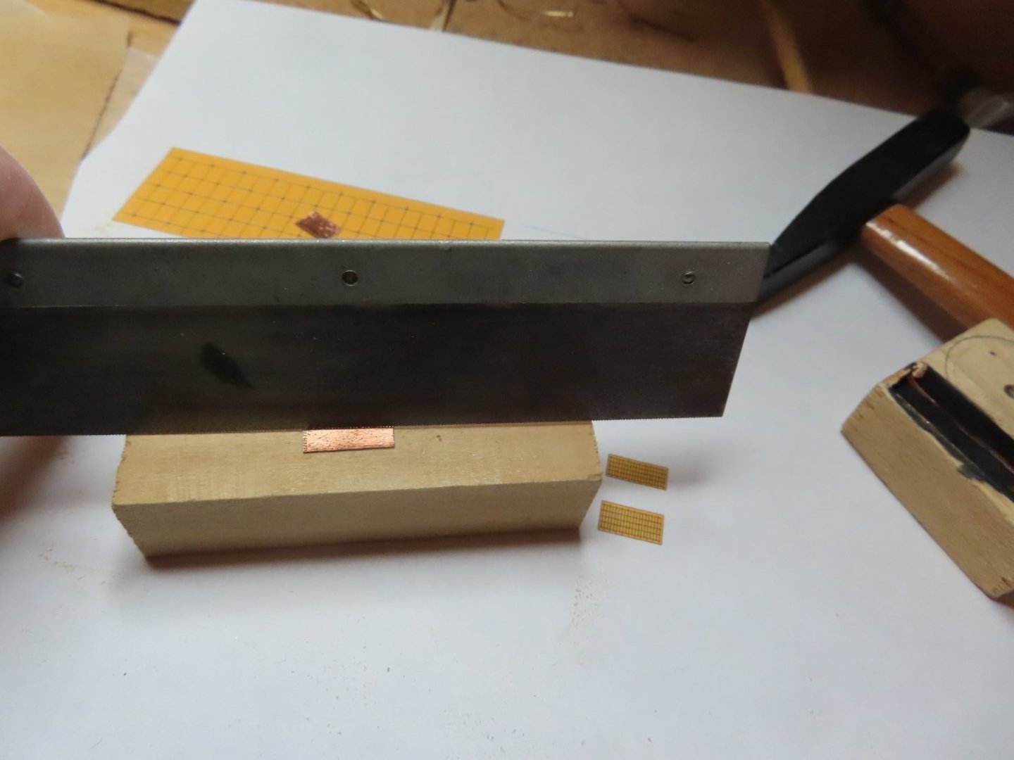
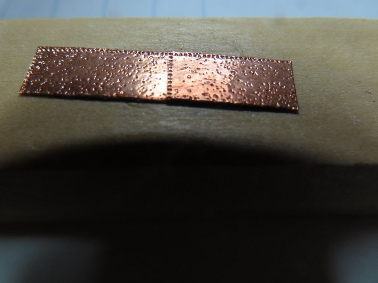
I have several choices for my copper plates: Full accuracy - Make an embossing stamp for ½” x 3/16” plates. Problems, the copper tape is ¼” wide, I need to make the stamp and jig to create 50 interior dimples plus a method to make the close quarter edge dimples Impressionable – give the impression of nail indentations only No nail impressions at all and may or may not overlap the plates I made the pattern for the fully accurate pate by counting the nail heads and their locations on the real plates from photographs. When I reduced the pattern down to scale size, the nail pattern would be indiscernible let alone easy to make. When I considered the number of plates needed, I didn’t think it was worth the effort. What I call the impressionable method is relatively easy to do, but still tedious. The idea is to emboss the copper using sandpaper. The rough surface of the sandpaper would make random impressions in the copper just enough for the viewer to realize the copper has some texture detail, not enough to discern a pattern while cutting down the mirror finish of the copper tape. I do have a method for the edge nails using a method which I’ll discuss below The last method is just to add plain copper plates straight off the copper tape roll without any embellishments, just cut to size. The relies on the idea that the scale is so small, you can’t see the details. I felt that the impressionable method might be the best way to, but I had to make a test run first. I cut a few ½” length strips for my trial and create the plate with these steps: Cover the plate with a piece of coarse sandpaper and using another block of wood (not shown), lightly tapped the block so it forces the sandpaper into the copper. Per Nautical Research Guild’s Ship Modeler’s Shop Notes II, Pgs.138-9 I used a fine-tooth modeler’s saw blade and with a single tap embossed the edge of the plate top and one side. Just rubbing the plate with my fingers to burnish the plate smooth. From just a few inches away, any discernable pattern would have been lost in the full accuracy method, so this method is my choice.

-
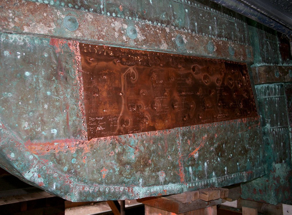
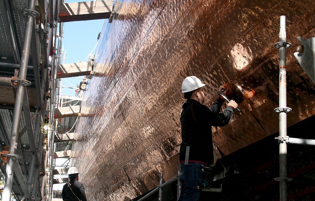
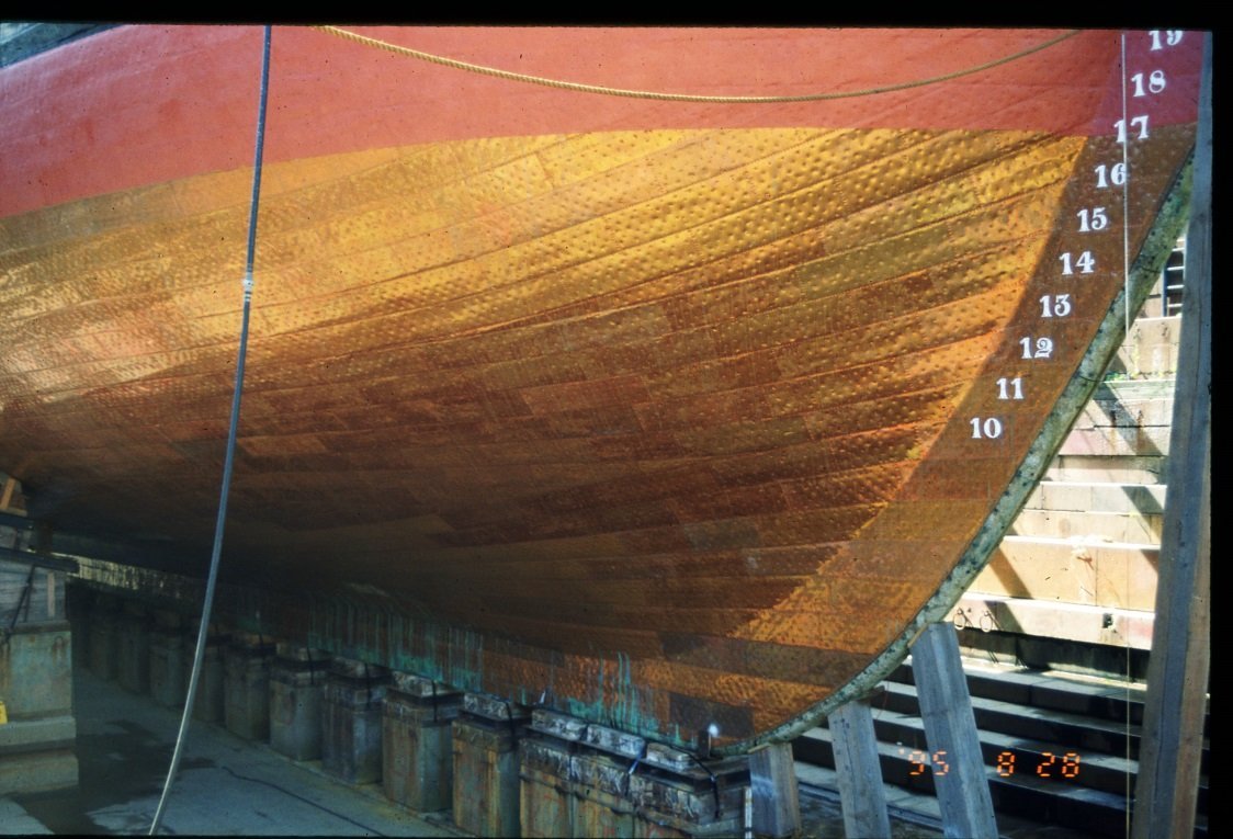
The practicum uses a coppering method which I feel could use a little improvement. Mr. Hunt used a ponce wheel to make plate edge dimples on the copper plate edge. Unfortunately, I feel they are oversized for the scale and look more like a boilerplate. A lot of builders used this method of just outlining the plate, and some made them with bumps raising above the plate like rivets. But after seeing actual pictures of the Constitution’s plating, I going to attempt an alternative method of embossed plates. According to Roger Frye’s Shop Notes in the Nautical Research Journal V66-4 Winter 2021: Per the quote above, the range between 1:96 scale and the Model Shipways kit at 1:76.8 scale, is left to the judgement and skills of the builder. The plate nails make small minor depressions so the indentations will have to be almost flat, just enough to disrupt the natural smooth mirror finish of the copper tape that is provided in the kit. The first image below is what Mr. Hunt created. The following images are of the actual ship for comparison.