JSGerson
-
Posts
2,633 -
Joined
-
Last visited
Content Type
Profiles
Forums
Gallery
Events
Everything posted by JSGerson
-
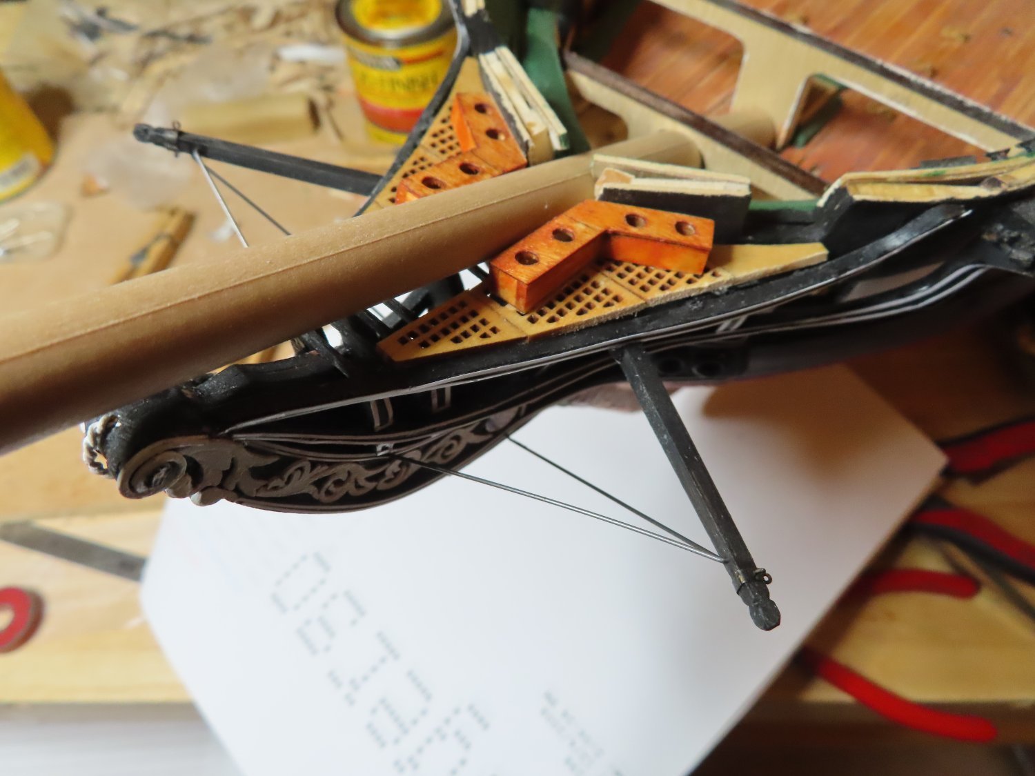
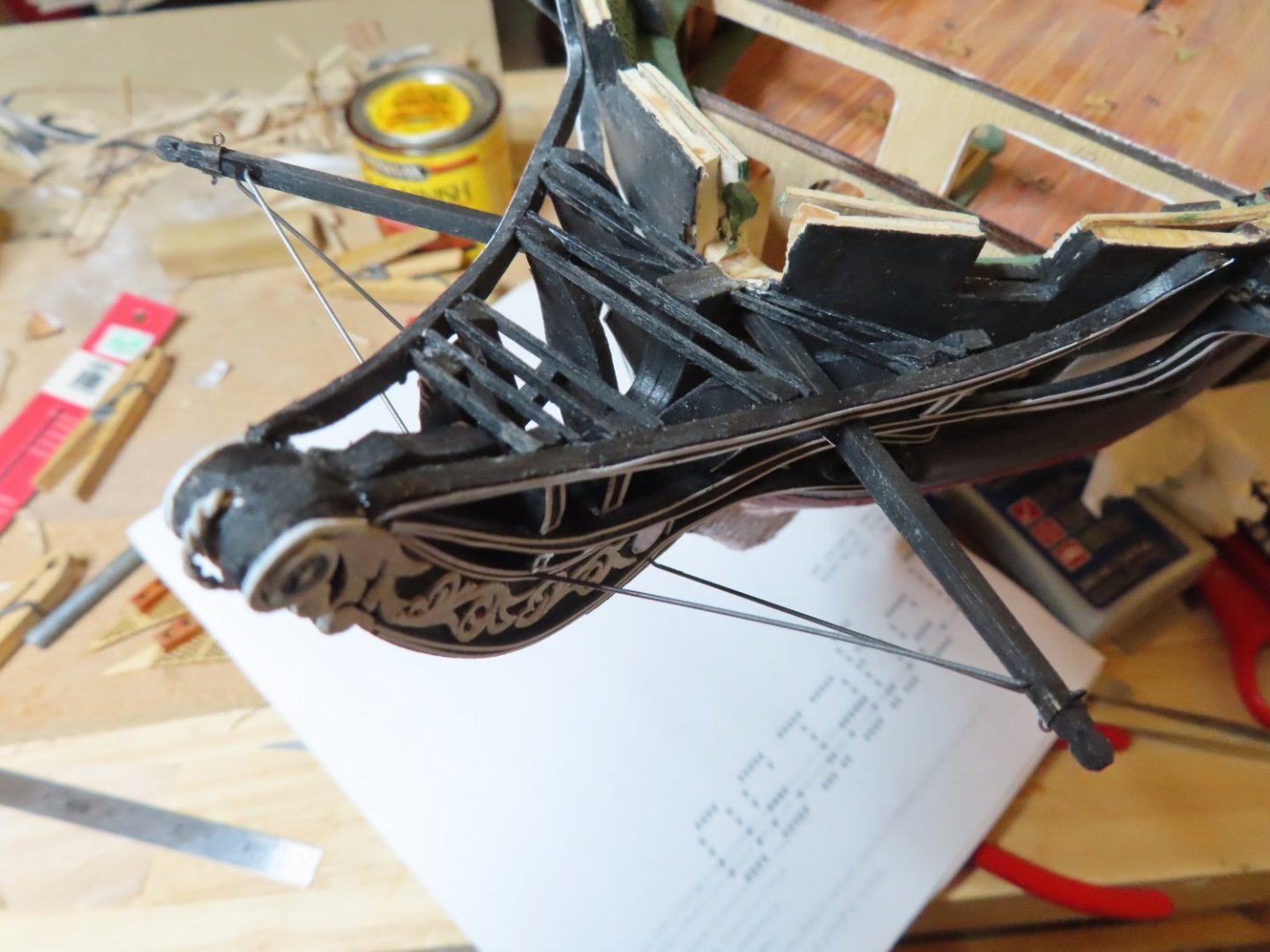
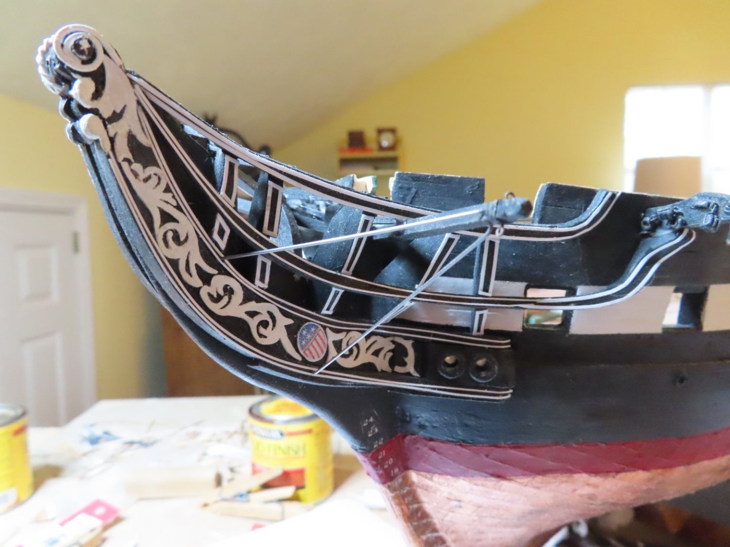
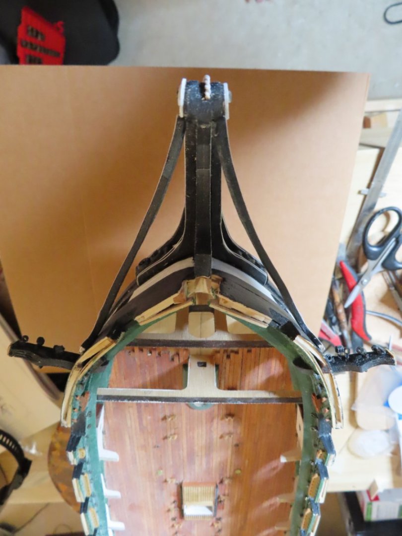
 There is a slight swoop up towards the stem tip that required some fine tweaking, but I eventually got the seat of eases installed on top of the rail support bracing beams. This image shows the seats installed with the unfinished bowsprit dowel dry fitted in place for show. The top rail will complete the bow.
-
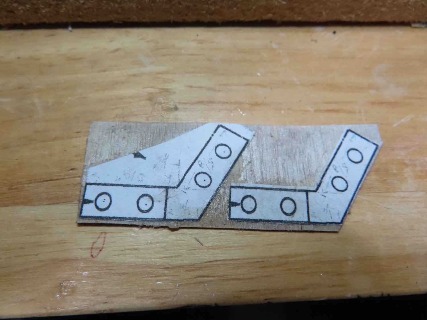
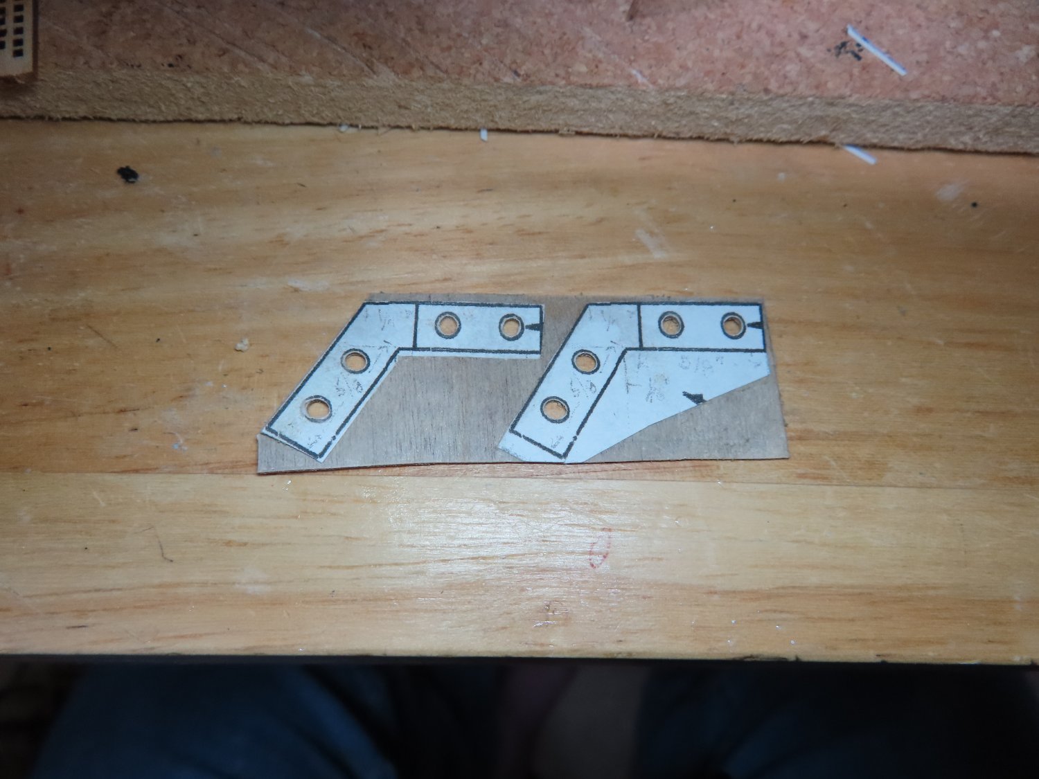
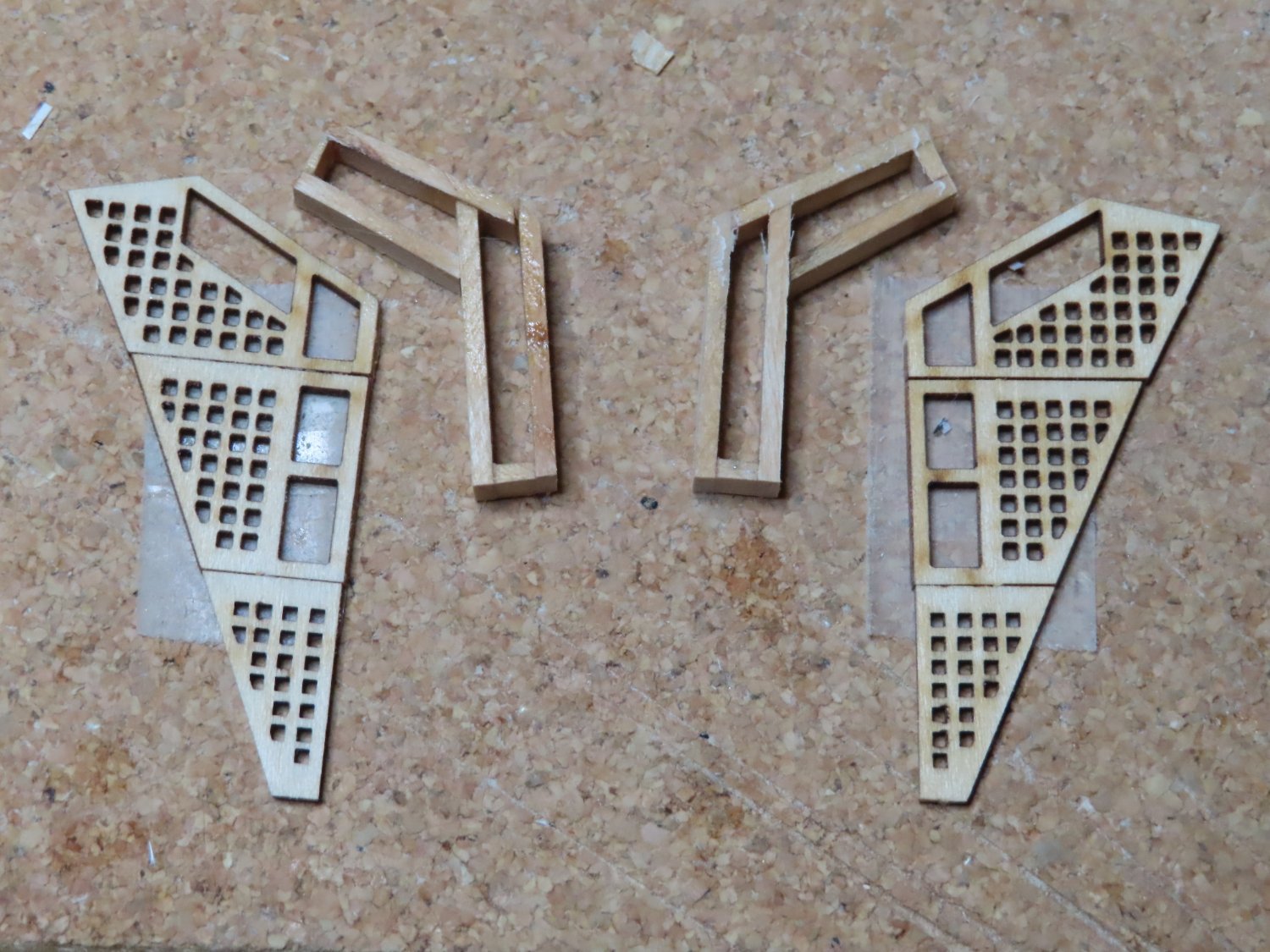
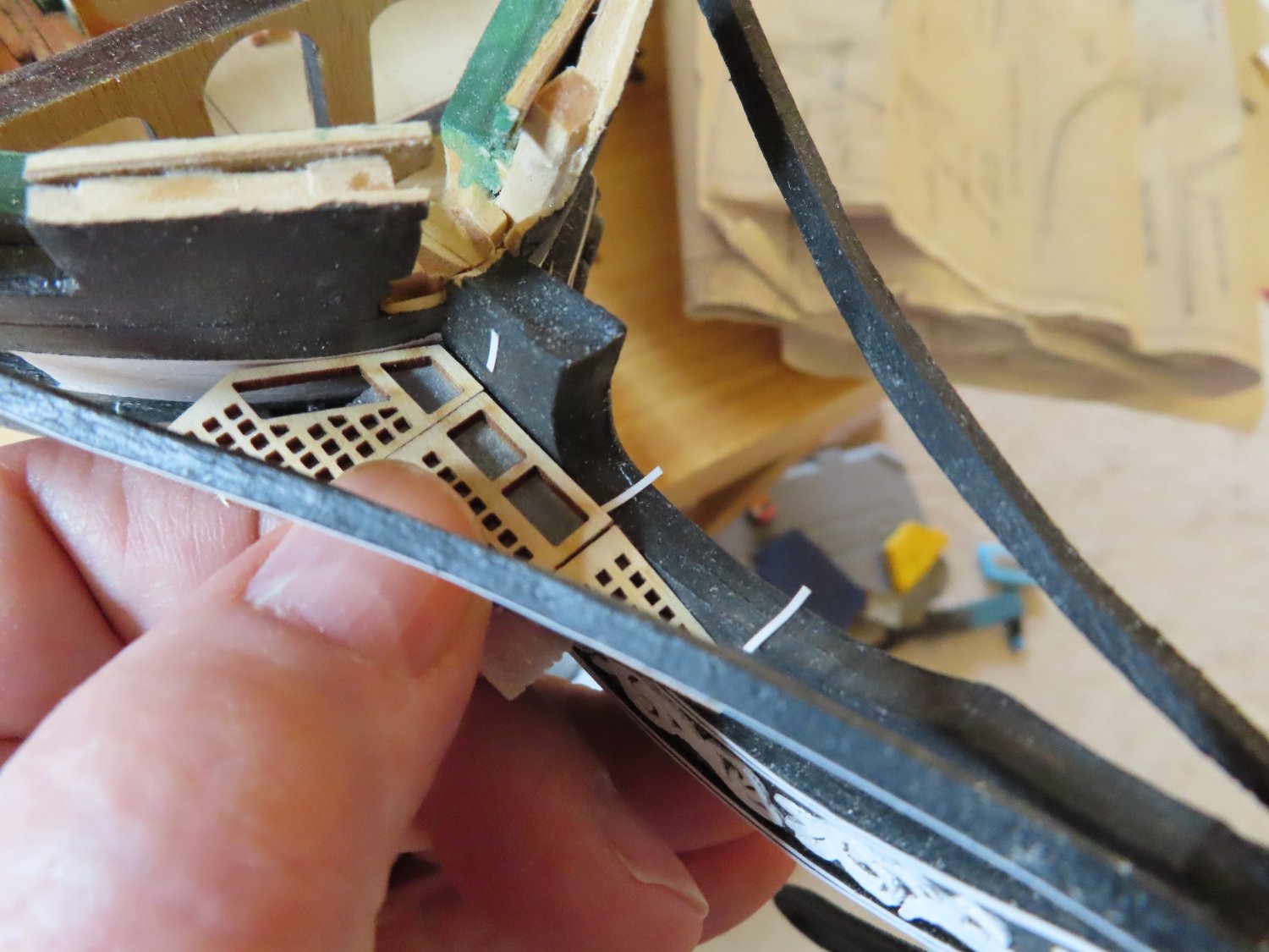
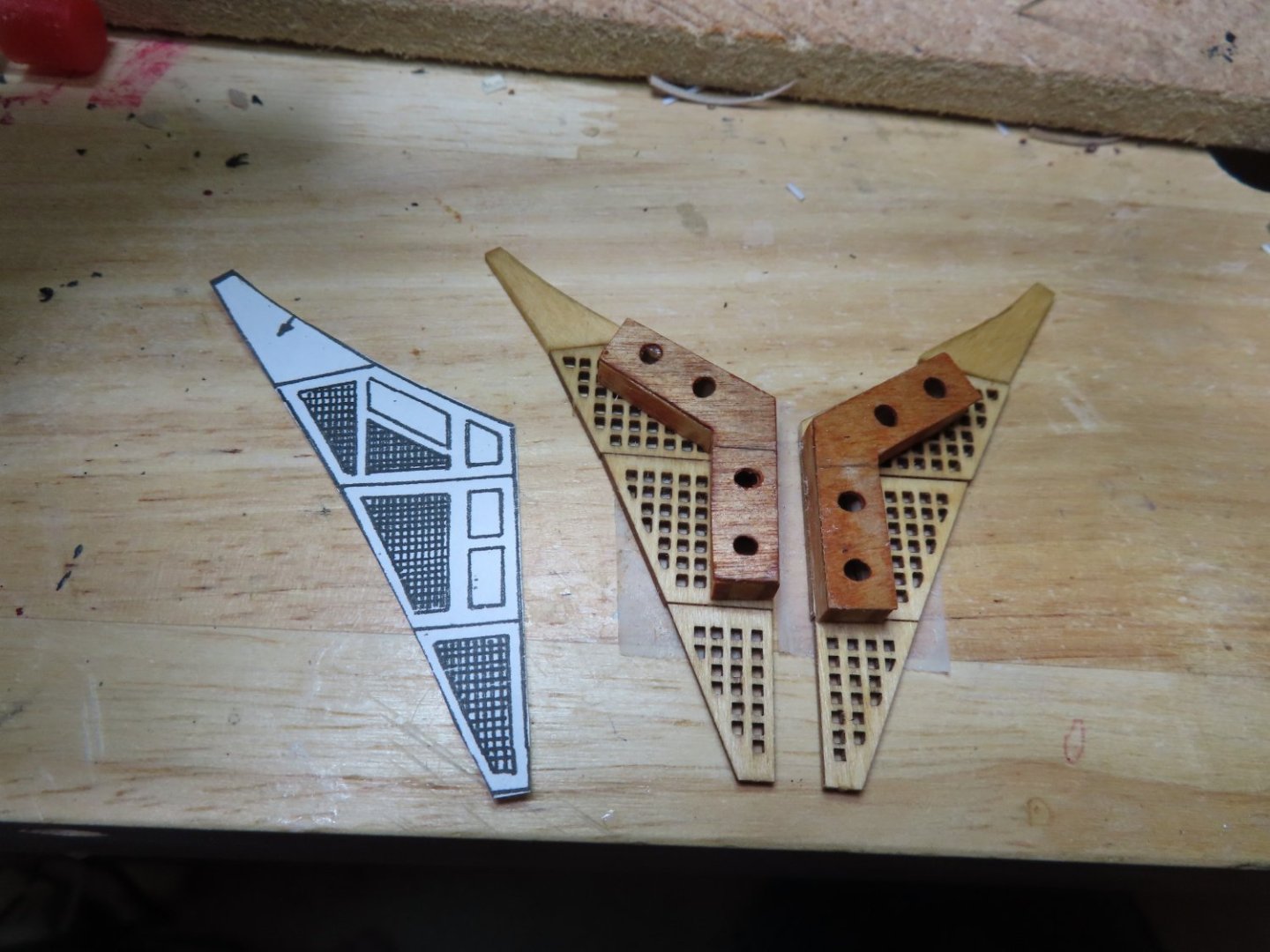
The top pieces with the seat holes had to be 1/64” thick because the seat openings exposed the thickness of the material. I chose to use 1/64” plywood for the top “L” shape pieces, for the required width of stock and its strength. The seat holes were drilled out before the parts were cut from the stock sheet to prevent breakage. A line was drawn both on the top and on one side of each of the components to represent a separation line that the actual ship has. It appears that the real seats were made in two sections each. Finally, solid wood triangular pieces were fabricated to complete the flooring. The final image shows the dry fit. Just as a note, Mr. Hunt brought up a point that the grid pattern showing the openings beneath the seats contradicts the pattern used to construct the seats. Specifically, the grid opening shape against the hull, is a parallelogram whose end forms an acute angle to the hull. The seat end, on the other hand, is at right angles to the hull. Mr. Hunt chose to make his seats follow the grid pattern. I chose the right angle based on a US plan (showing six seats per side) as well as some modern photos. BTW, finding any images of the bow showing the seats of ease area, are exceedingly rare because the public is not allowed in that area. No public, no pictures.


-
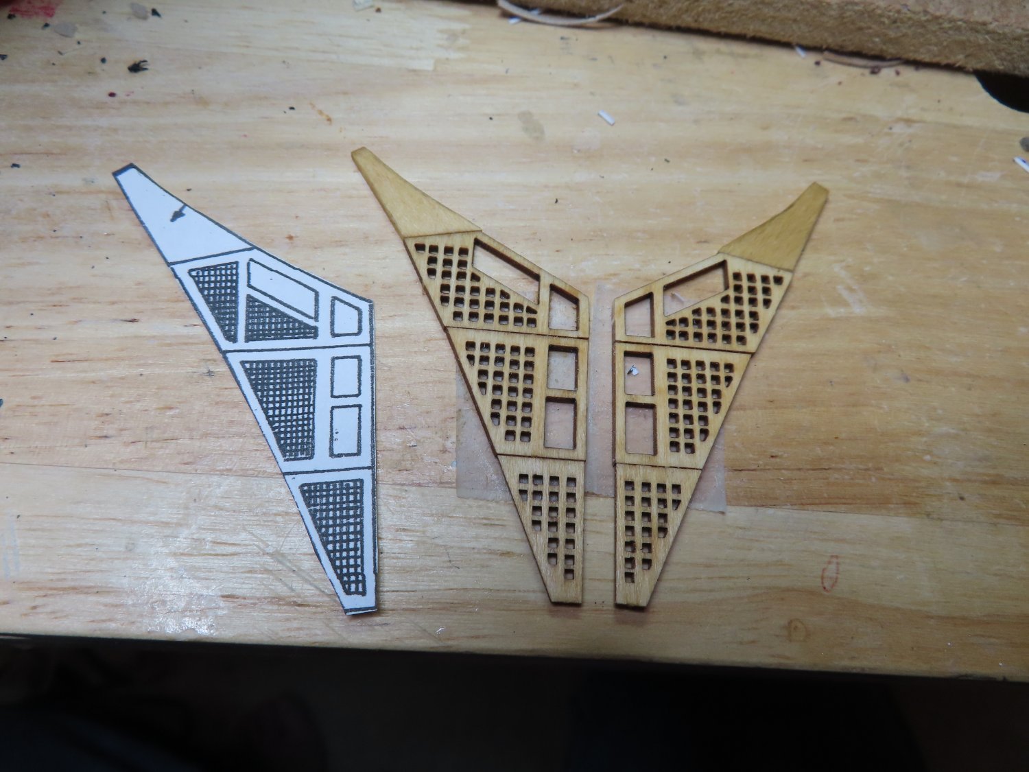
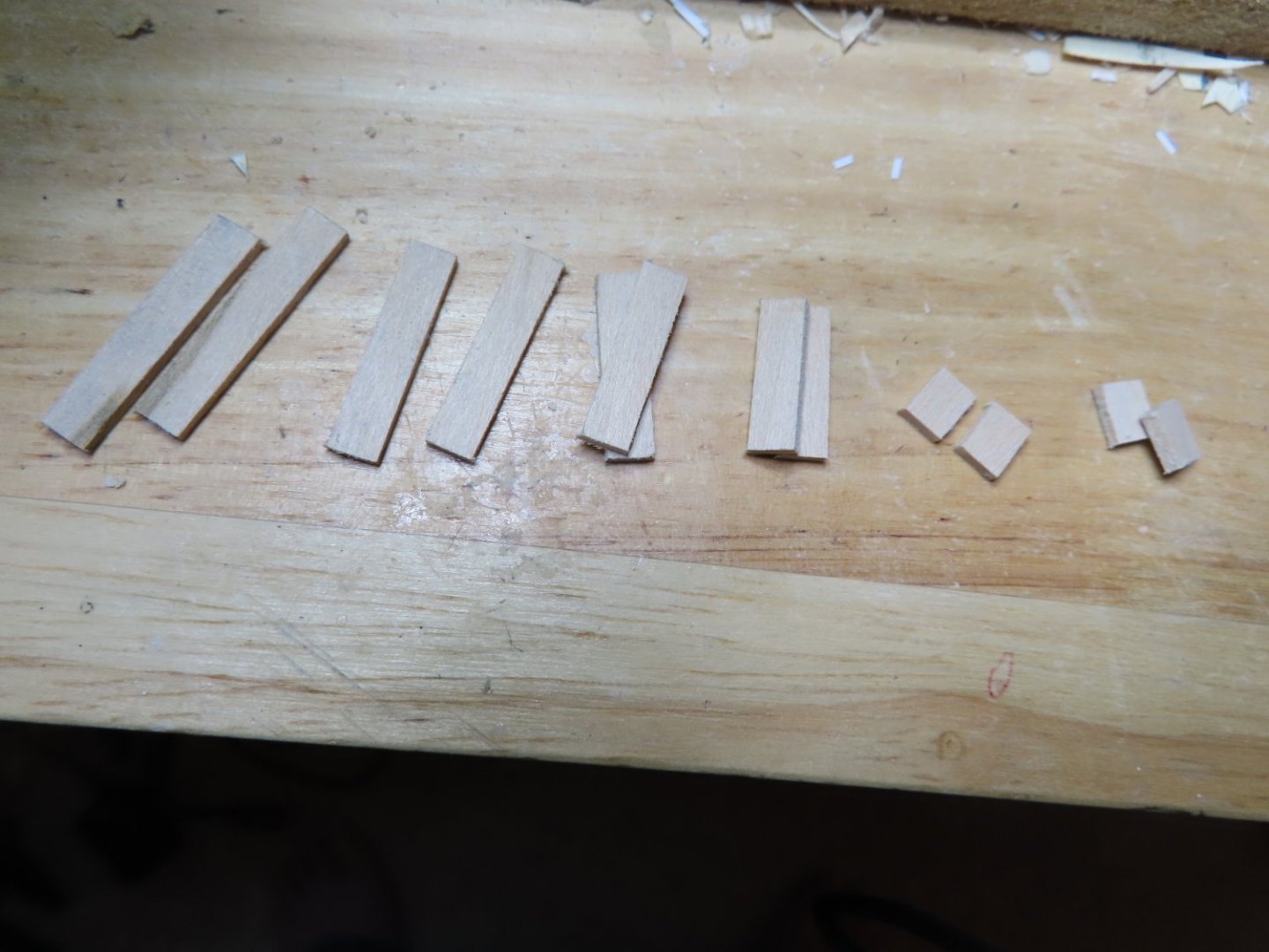
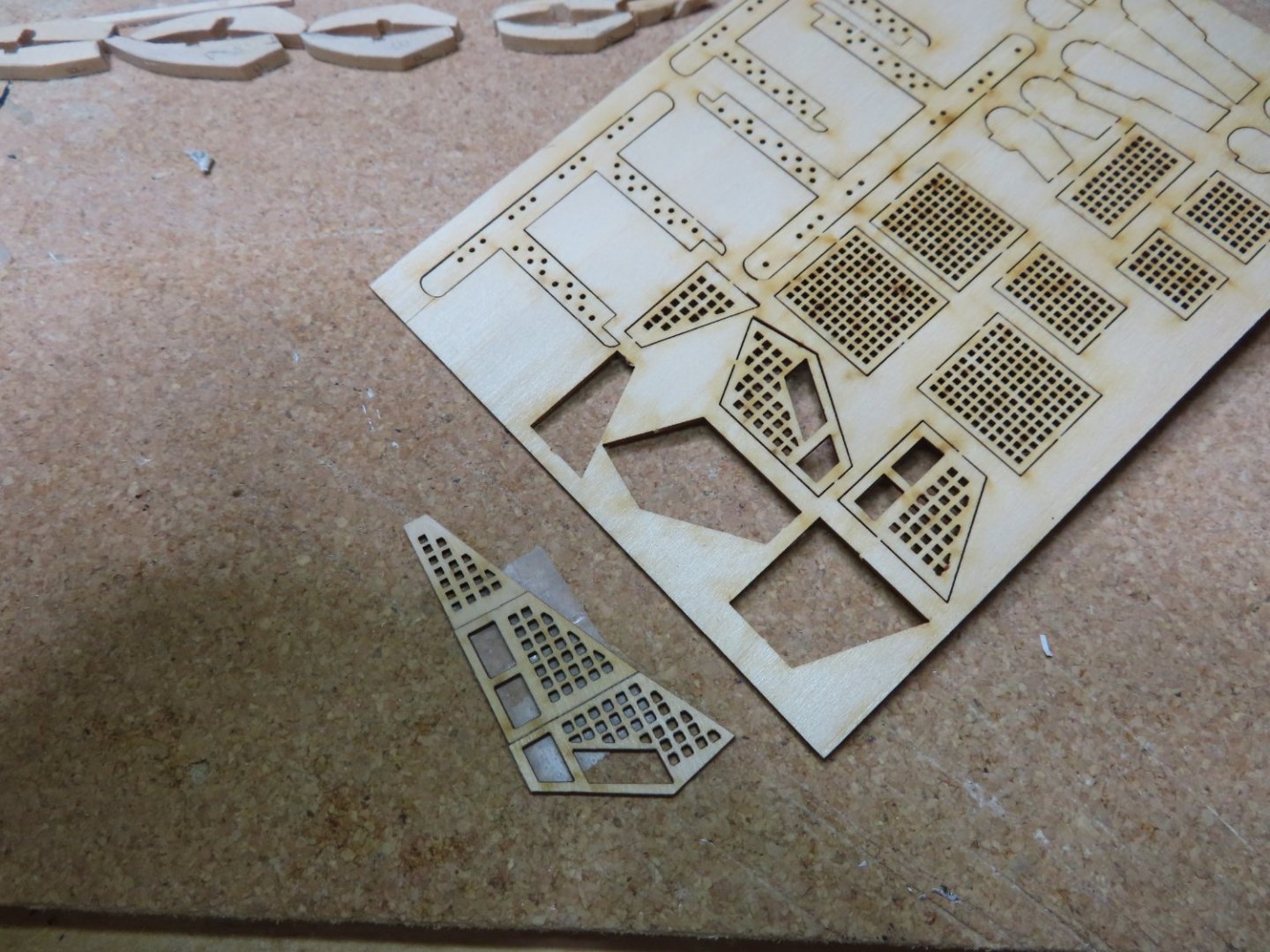
Grating and Seats of Ease The kit plans called for pairs of 1/32” x 1/16” rail support beams on either side of the rail supports. Accordioning to the plans both the kit and the US Navy, these cross beams are flush with the top of the rail supports. They support the gratings upon which the seat of ease rest. However, either I or Mr. Hunt misinterpreted the plans because at the end of Chapter 8.1 he states: “I chose not to model these as it's nearly impossible to see them.” See them or not, they are important as I interpret the plans. As result, his construct of the gratings and seats of ease, are lower than the cross beams had he installed them, while mine are resting top of cross beams. Be that as it may, here is what I did. Following the practicum, I cut the seat of ease side pieces from 1/16” basswood stock and assembled them using the kit’s plan as my template. The kit actually called for 1/64” thick pieces to be used, but since their thickness would not be seen by the viewer, the thicker pieces were more stable and easier to handle. The kit provided three laser-cut pieces of the grating for each side, which I temporarily taped together for dry fit purposes.

-
I assume the boomkins on the actual ship had some sort of fasteners to hold the beams in place to the hull, but I could not find any information on that. Therefore, they were just glued into place. The boomkins did have two metal rod hull braces each. The kit called for 0.023” wire for these braces. I needed something stiff, so brass and copper wire were not suitable, but I did have “0.020” and 0.026” music wire. I chose to use 0.026” wire in lieu of 0.023”, which I did not have. Holes were drilled into the hull and boomkins in the appropriate places following the kit plan with a #72 drill bit. After a little trial and error, the wire s were sized for length and the wire ends bent for the appropriate holes.
-
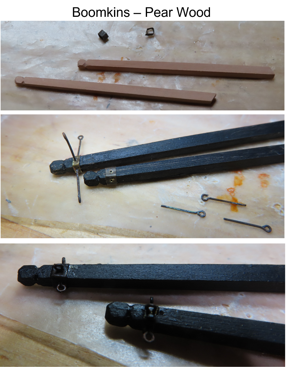
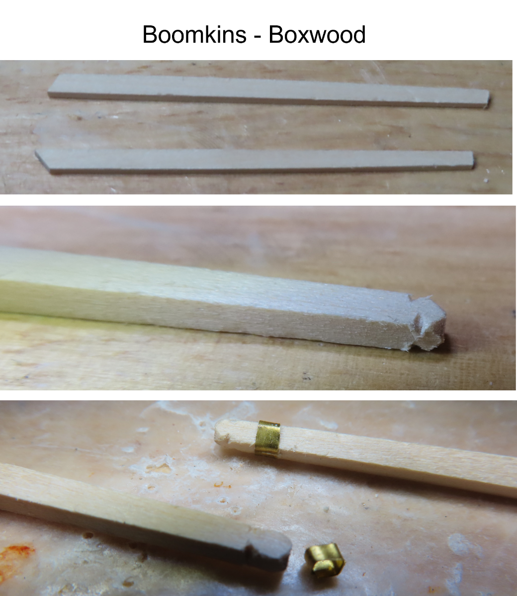
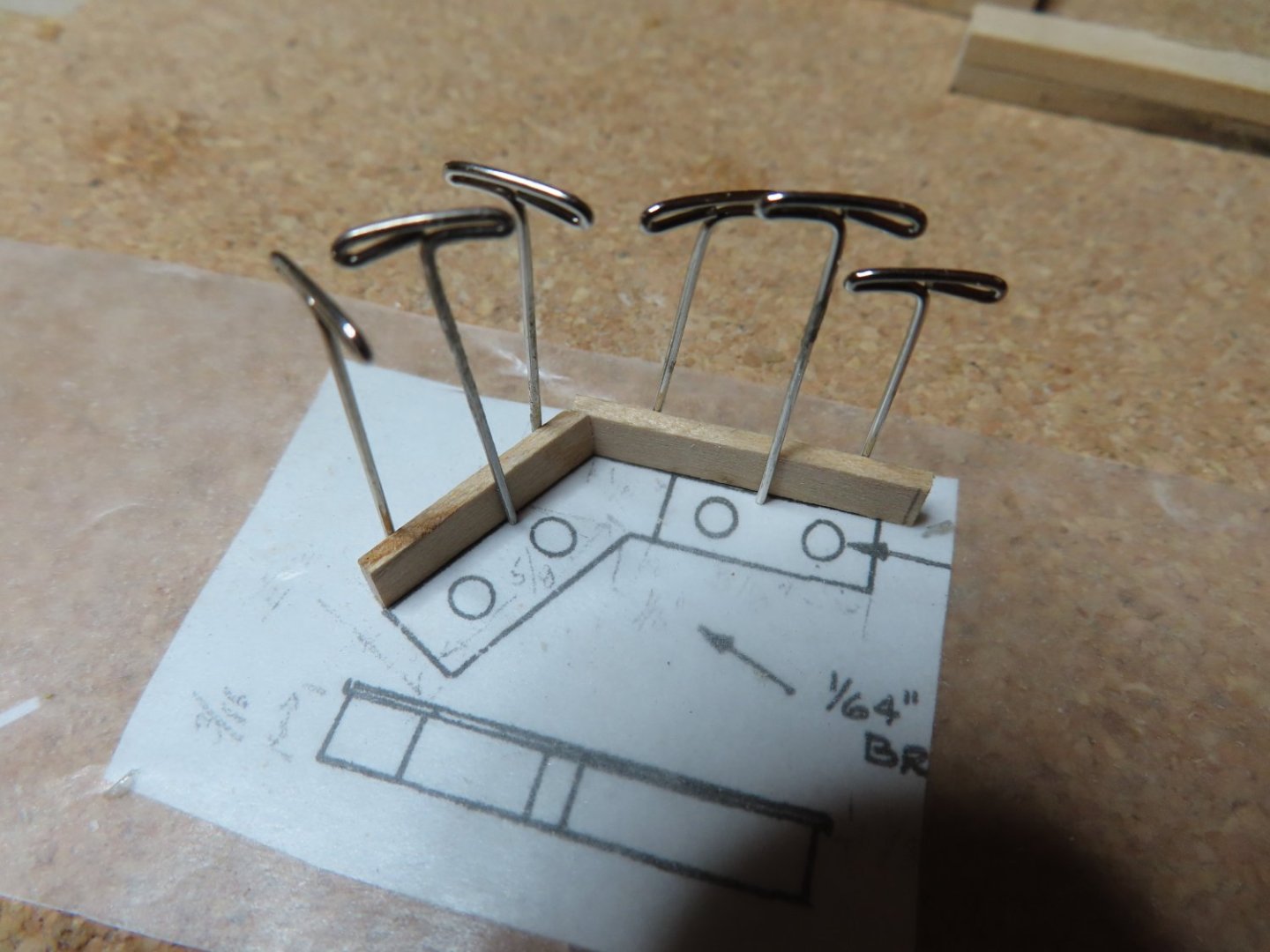
Looking at my efforts, I realized I needed to do this all over again but with a harder wood because the square edges of the boomkins were already beginning to wear down during the fabrication process. Using 1/8” x 1/8” stock pear wood that I had left over from when I constructed my Rattlesnake, the results were much better. They were then painted black. The brass bands held three eyebolts. Two eyebolts, one on the aft side and the other on the bottom of the boomkin, were aligned lengthwise following the line of the boomkin. The third eyebolt located on the top of the boomkin was installed perpendicular to the boomkin as was shown in the various photographs of the actual ship. To do this, a pin was used to make the initial dent in the brass for the #77 drill bit. The holes were drilled through the brass into the wood. After each hole was drilled, a full-size eyebolt was inserted so the brass band would not move while the next hole was being drilled. Then the eyebolts were removed, cut to size, and permanently installed with CA glue. This secured the brass bands as well.

-
Bow Boomkins I was about to install the grating and fabricate the seats of ease in the bow when I realized that the pair of bow boomkins needed to be fabricated and installed first because they were physically below the grating. Surprisingly, the practicum did not address these components. Initially, utilizing the kit’s 1/8” x 1/8” stock basswood, the boomkin were fabricated by tapering the pieces of wood to 3/32” x 3/32” at one end. Then, with a square cross-section needle file, the triangular indents on the tapered ends were formed. Using 0.005” brass metal sheet, two strips of the metal were cut to size, wrapped around the boomkins to form the brass bands, and then blackened.

-
I've collected and cataloged about 1,000 images of the ship over the years, so if you need an image of a particular item, just let me know. The chances are good that I will have a number of photos from different angles of it. Jon
-
Welcome back. I've been working on this kit slowly but steadily for about 5 years now, and maybe half way through. Of course that may be because I've added a gun deck which Mr. Hunt did not do. I look forward to your build log restarting. Jon
-
From your images, the green looks good to me. Like all painted surfaces, how it looks depends among other things, on the light source. Go online and find an image of the bulwarks in the full sun and compare that with your model under the same type of lighting. Then decide if you need to adjust. Jon
-
I noticed the fine detail work on the trailboard and was wondering how you got such nice results. I had a devil of a time making mine at 1:76.8 scale and your model is even smaller at 1:100 scale. The paint work is fabulous. That must of taken a very fine brush and a very steady hand. Well done!
- 88 replies
-
- 1
-

-
- Constitution
- billing boats
- (and 1 more)
-
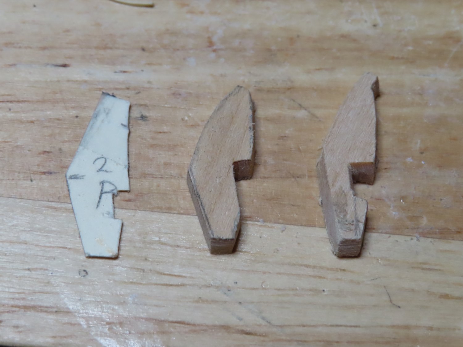
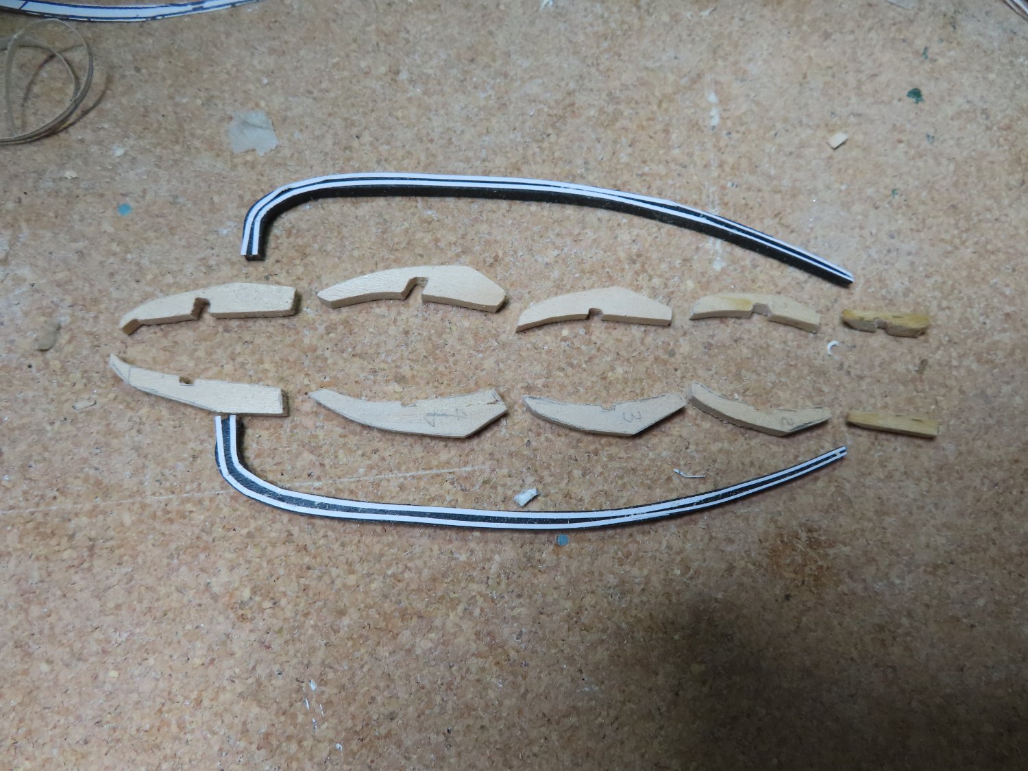
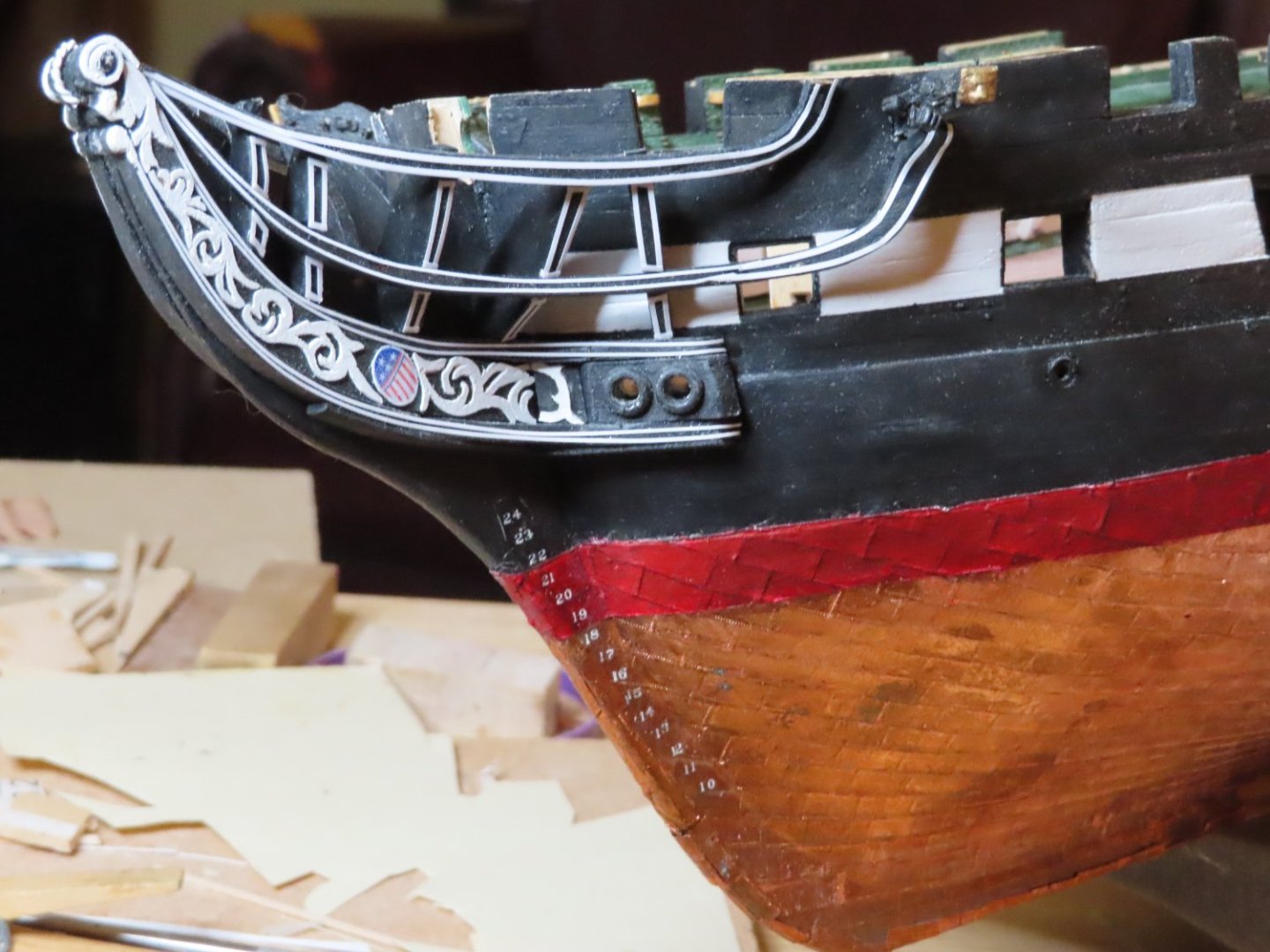
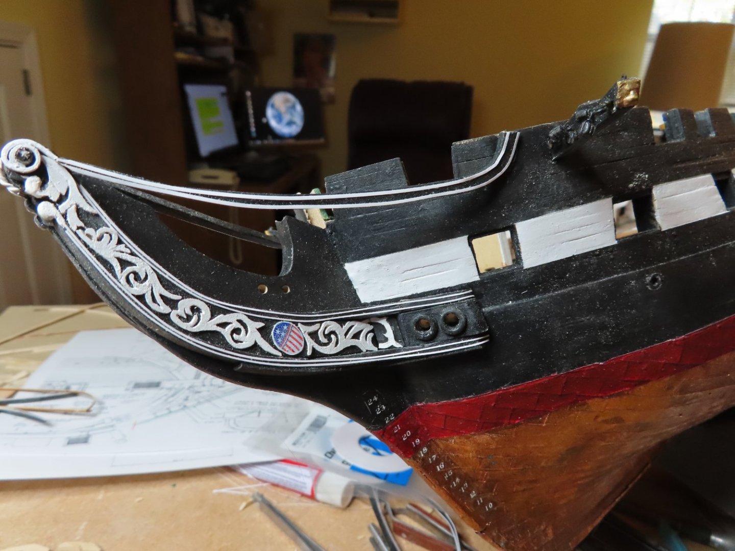
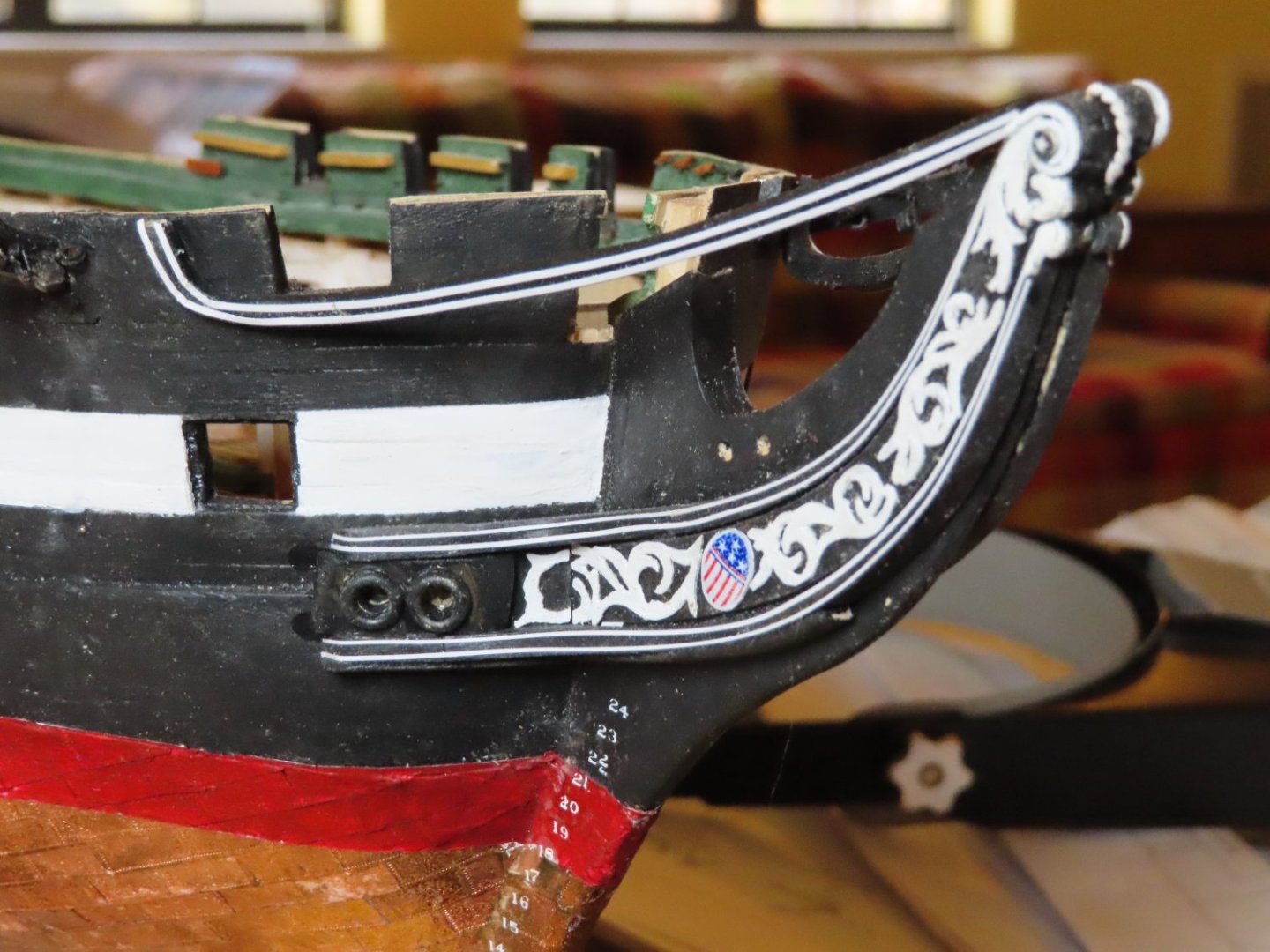
As I mentioned in an earlier posting, the MS plan drawings of the rail supports do not fit properly on my model. Whether I’m at fault or the plans are, is immaterial. These have to be custom made now., By trial and error measuring using card stock, a first try template was drawn and cut out of the cardstock. Once I got the card stock to fit, it was traced onto 1/8” thick stock wood. Once I got the wooden piece to fit, I realized that it had to be refined a bit more. A second wood rail support was fabricated. This was able to fit properly onto the rails. The support was removed, painted and pin striped. Finally, it was installed. This was repeated the same manner (with or without an extra preliminary wood support as needed) for the remaining nine supports.


-
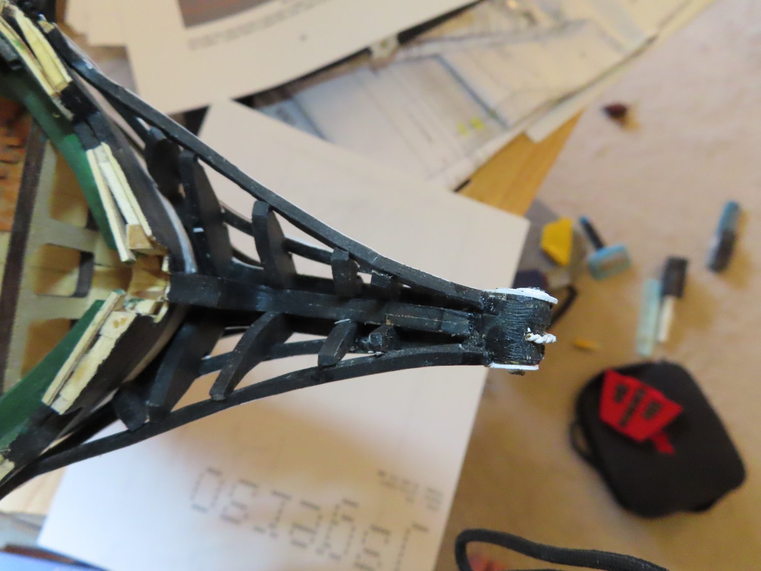
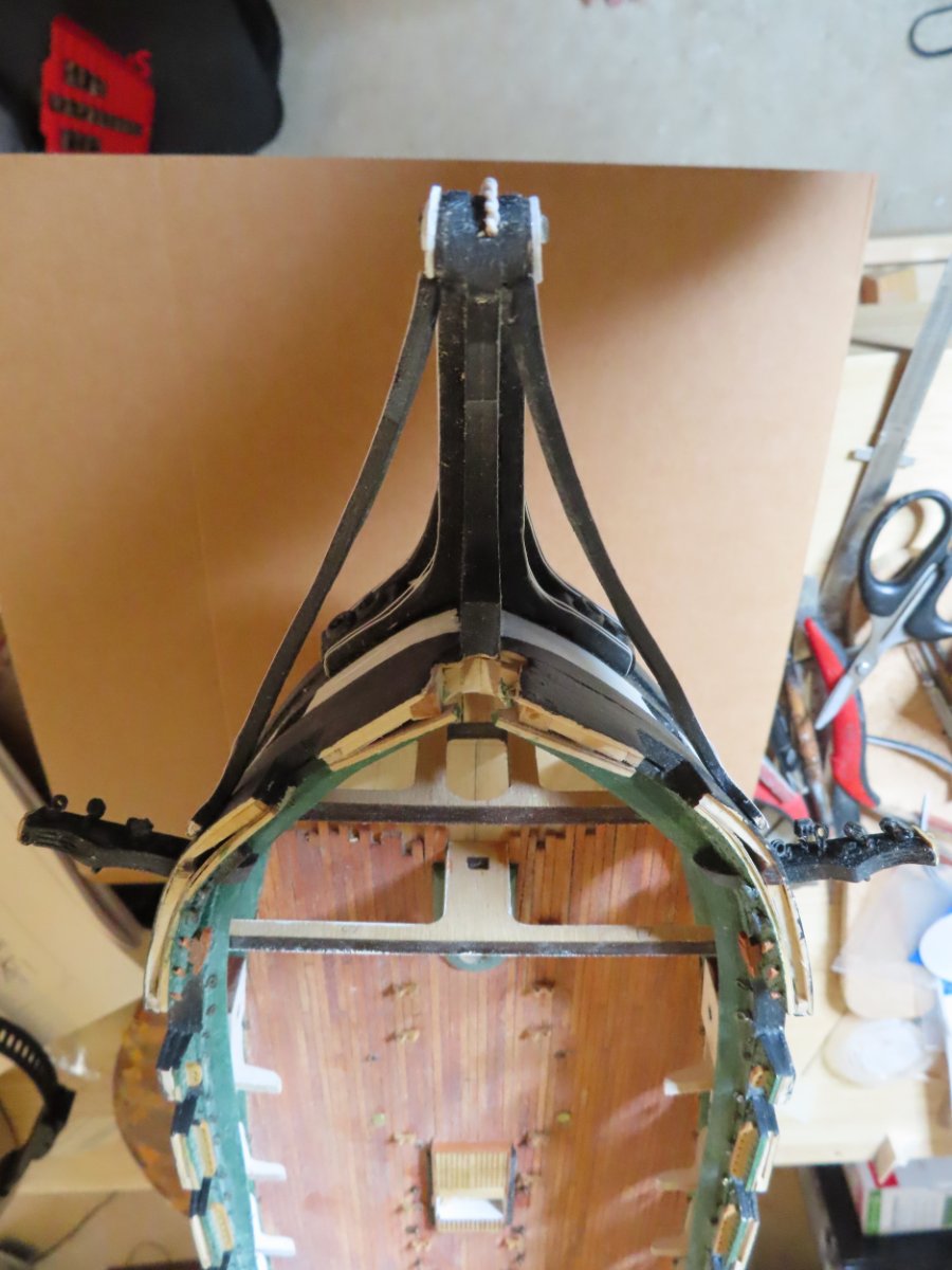
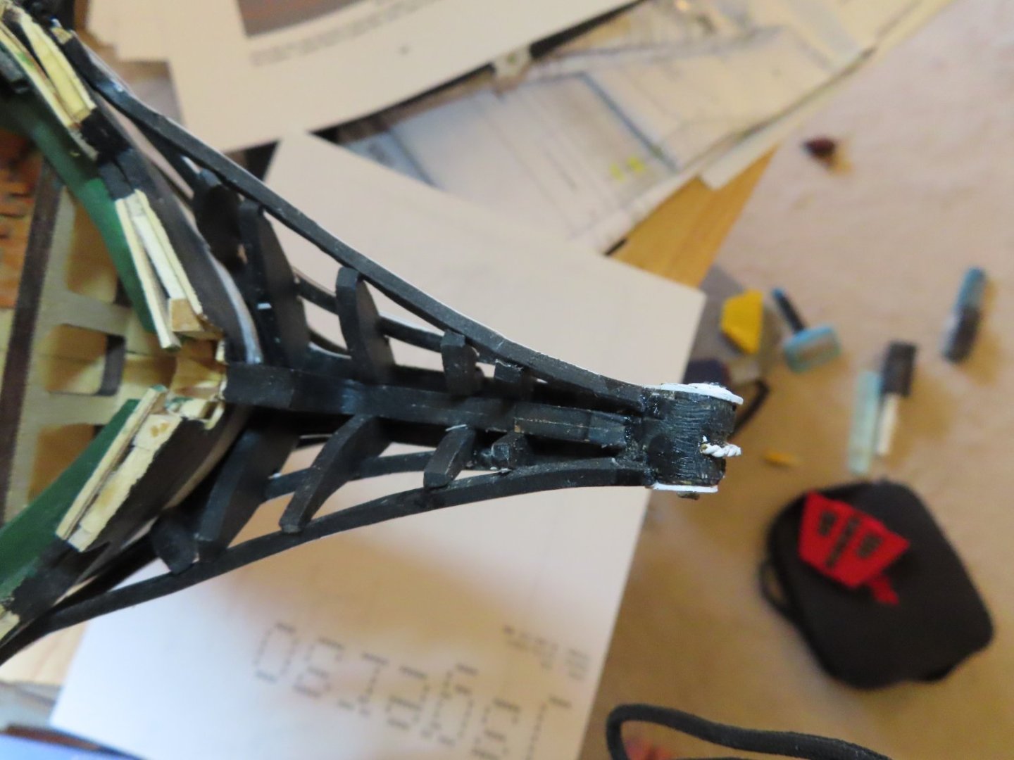
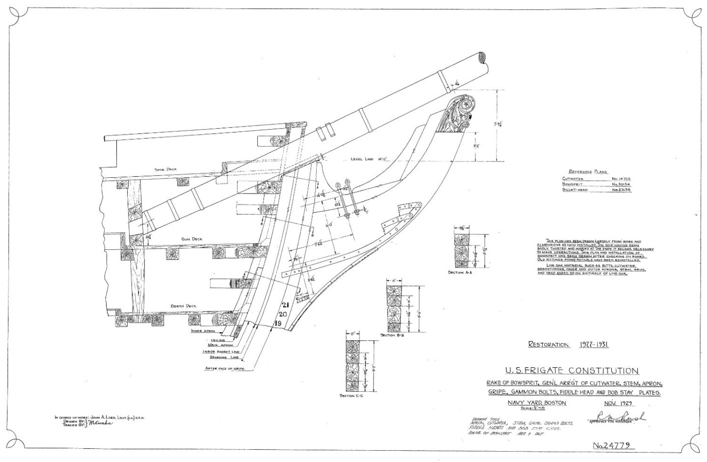
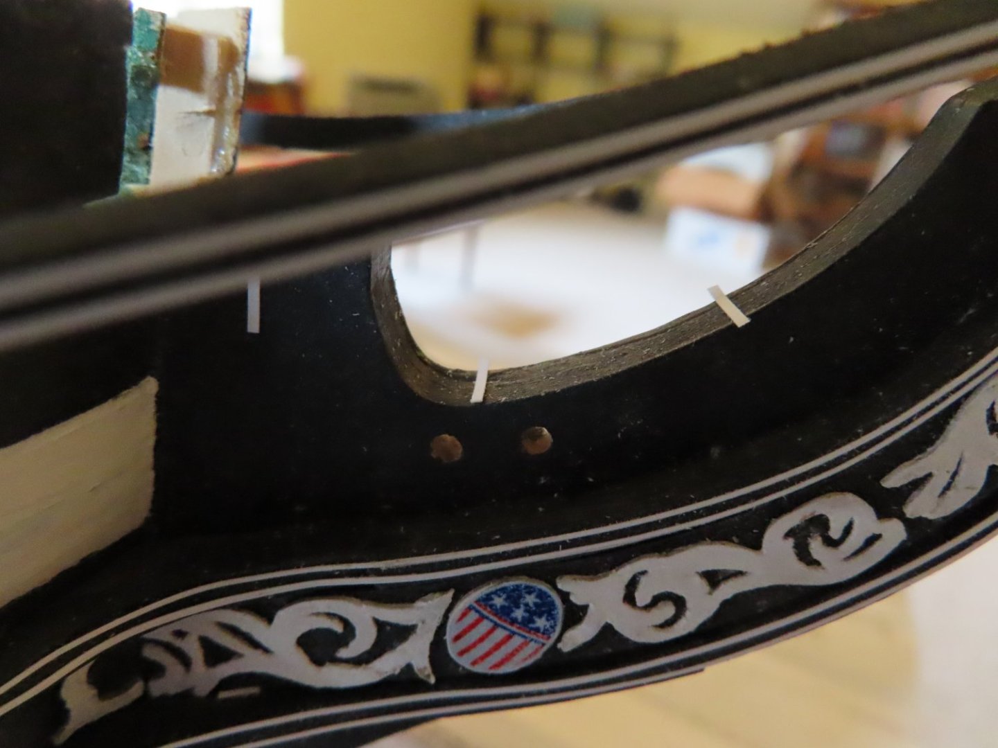
This is when I discover a new problem. According to the MS plans, the precut gammoning holes in the stem are supposed to be between supports Nos. 2 and 3. Per the marks I just made with the gratings, the gammoning holes straddle rail support No. 3. The gammoning holes are where the gammoning chains pass through. Looking at the US Navy 1927 -31 Restoration plan No. 24779, the gammoning holes have been replaced with eye bolts embedded into the stem. The gammoning chains are then connected to the eye bolts. The chains are fastened to the bowsprit in the same manner as shown in the MS plans. These stem bolts are positioned half the distances apart as the pre-cut holes are and appear to be straddling rail support No. 3 from the numerous photos that I’ve looked at. Based on the all the ambiguities, just about nobody will even know about or bother to look inside the rails supports to see if there is even any gammoning there, let alone whether it is correct or not. Therefore, I am going to use the existing gammoning holes as they exist on my model in lieu of the embedded bolts shown on the US Navy plans, just because as builder of the model, I like the way they look.
-
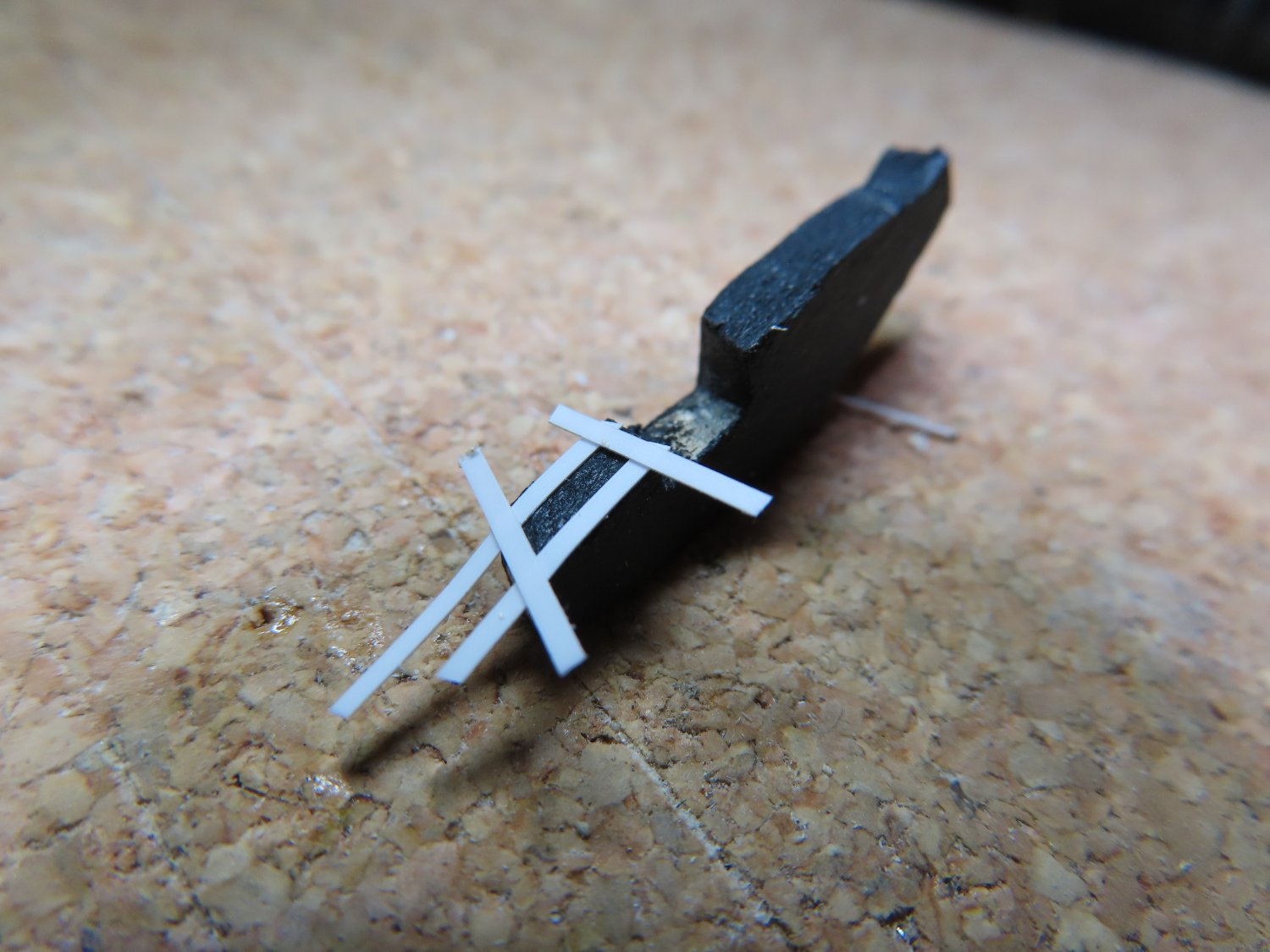
Now it’s time to install the rail supports. These are positioned such that the joints of the floor grating in the seats of ease area, rest on the horizontal structural beams attached to the rail supports. In other words. Where the gratings meet, that is where the rail support is supposed to be. Using the grating parts supplied in the MS kit, I taped the three pieces together that make up most of the flooring, to mark off where the joints are with the architect tape on the stem.

-
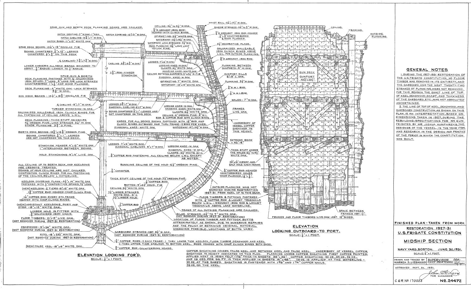
I don't know how much "easier" building a cross section is than the full ship. The cross section has a lot more detail below decks. You might want to look at Tom Culp's build of the Model Shipway' Cross Section of the Constitution. In the mean time, I've attached a number of US Navy plans showing the cross section. You can find more plans with other details at the US Constitution Museum website. 130241 - Midship Section sh1.pdf 34535001.pdf


-
Good to see you back and look forward to your future posts. I been working on my Conny since 2017 and still have not finished the hull. I've been using Mr. Hunt's practicum only as a guide as I am adding the gun deck to my model. Nice work on the electric guitar body. Jon
-
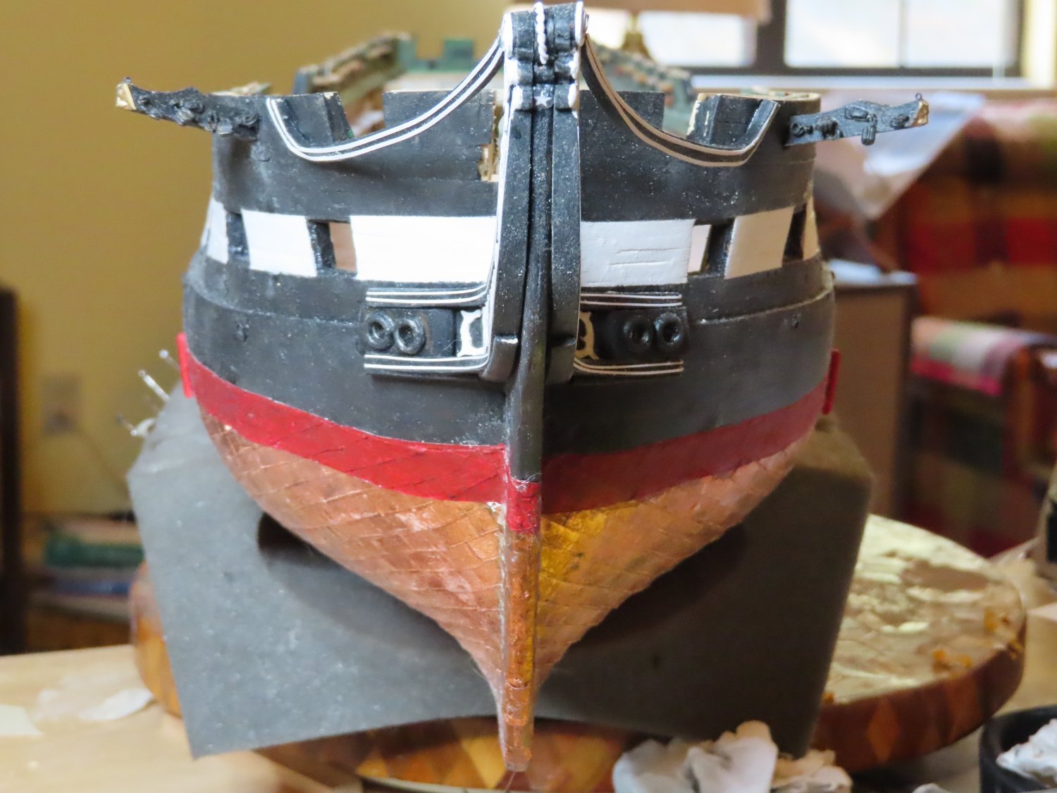
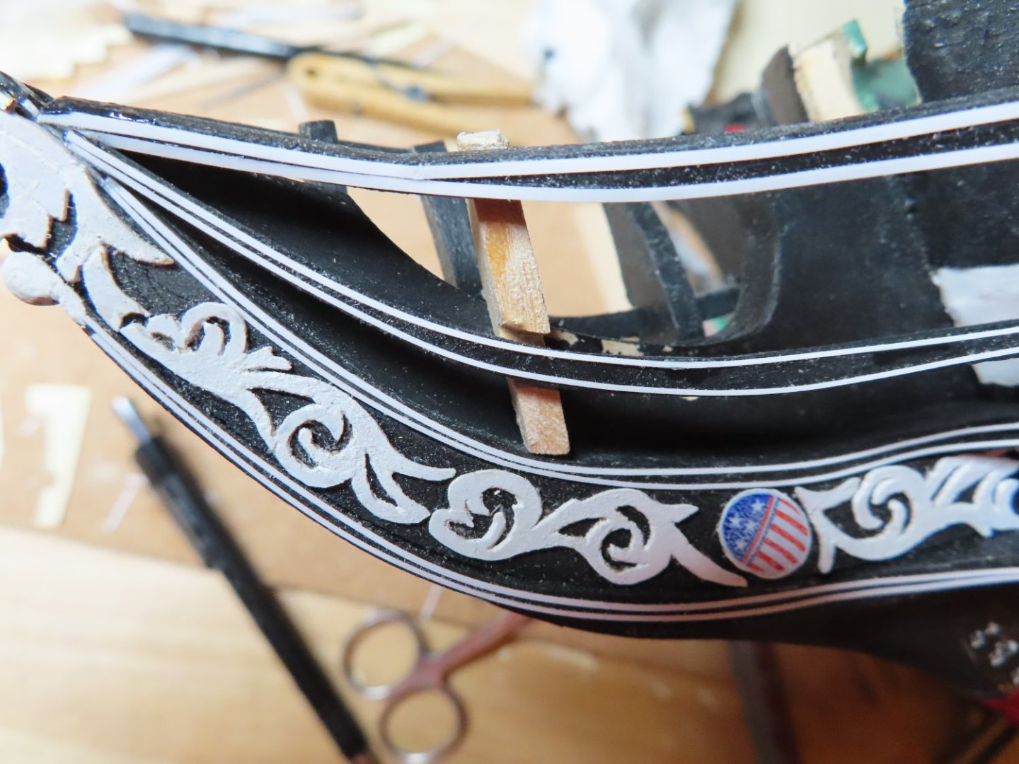
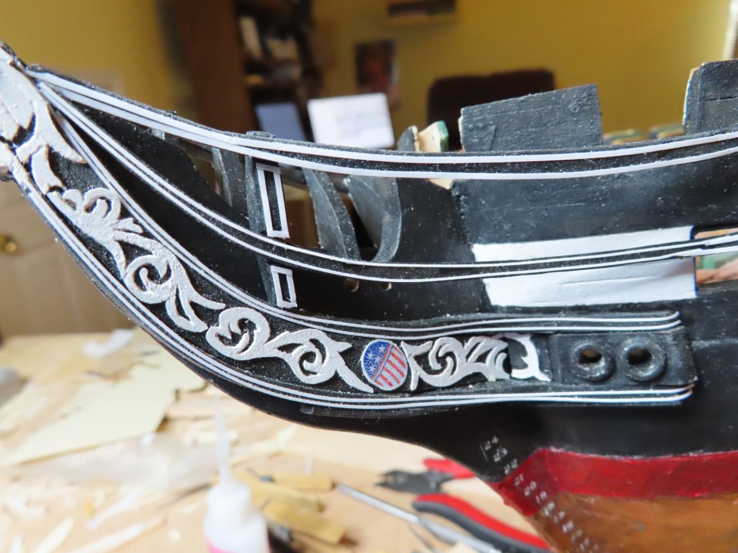
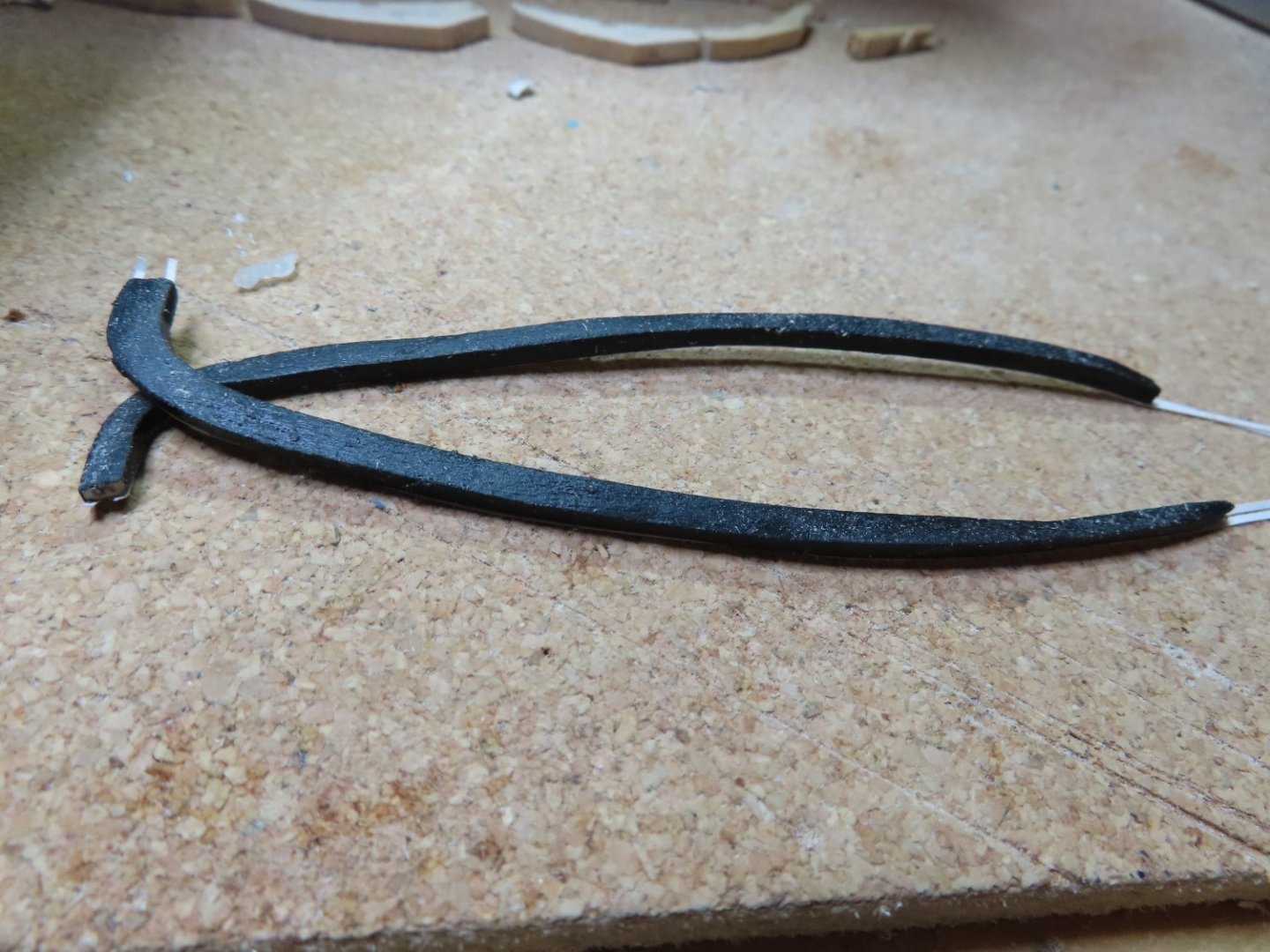
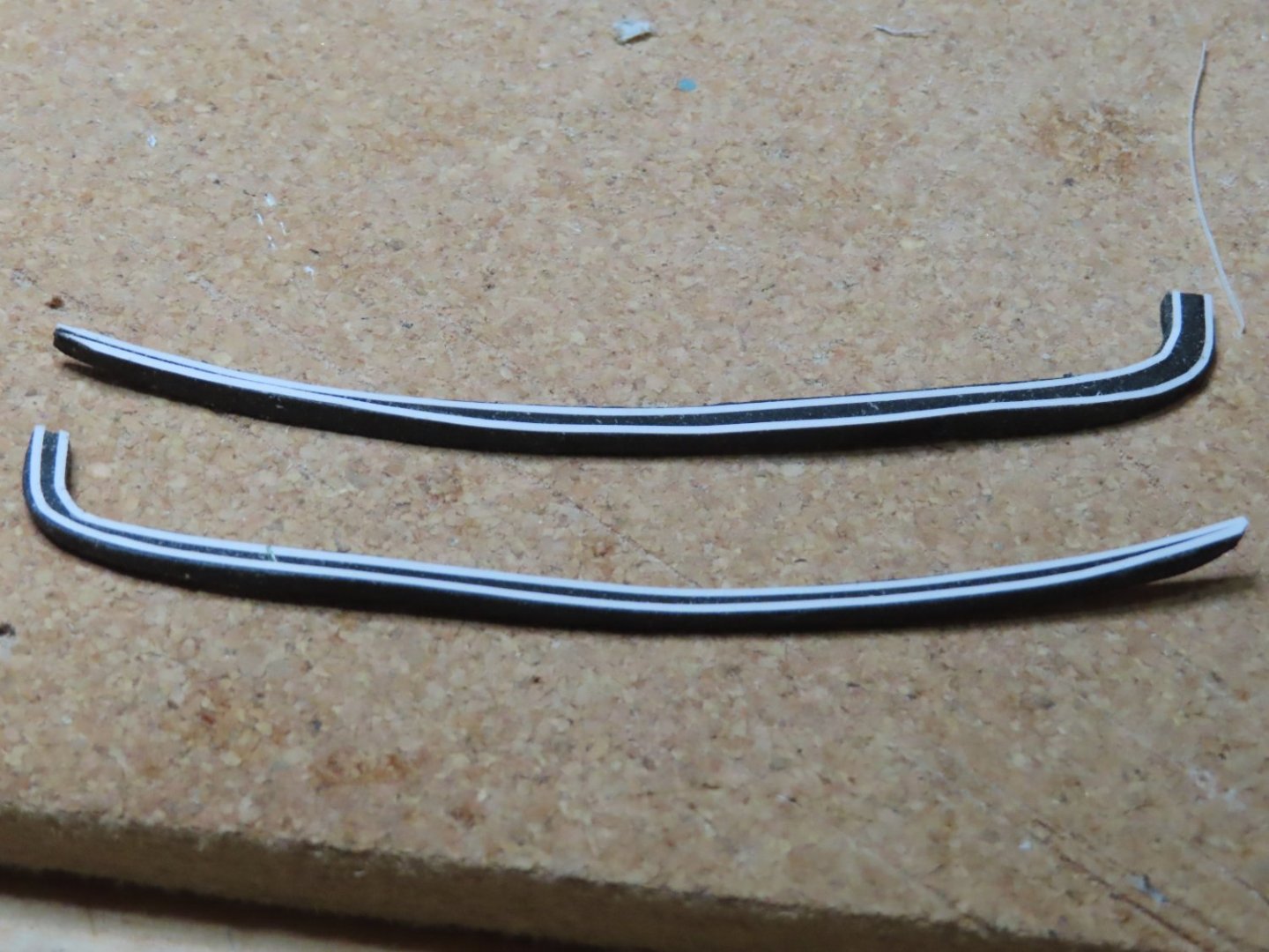
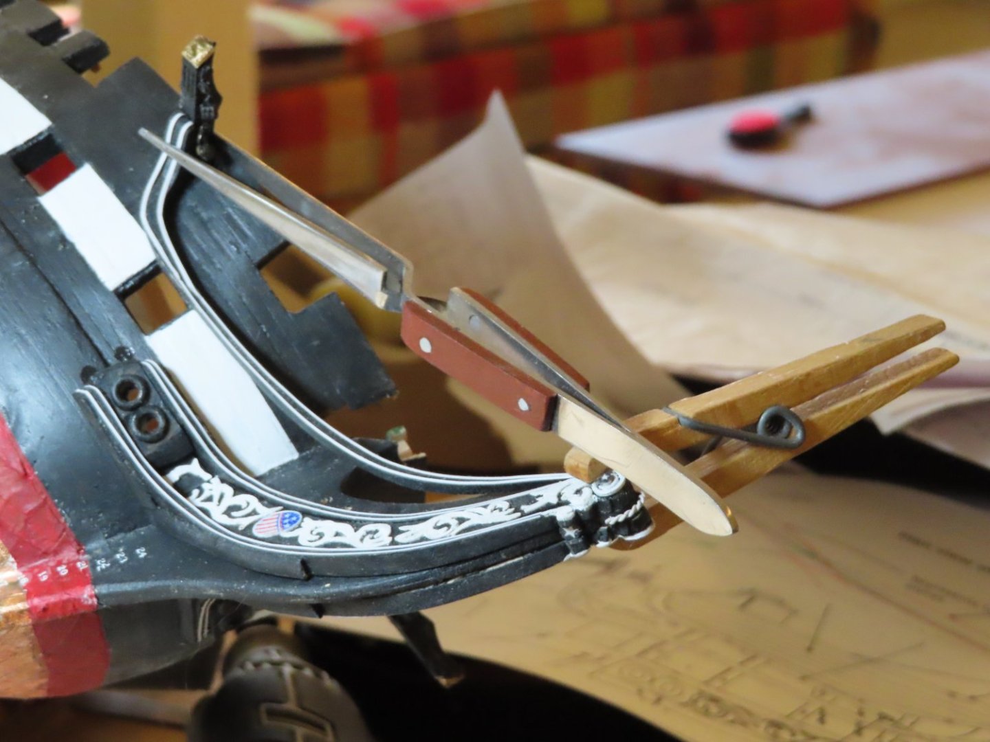
BTY, I’m not knocking Mr. Hunt’s practicum. I could not have gotten this far if it weren’t for it. But I have learned that he’s human and he's the first to admit that his way may not be the best which is why in addition to using his practicum as a guide (not my bible), I also check how other builders solve these problems. My second fabrication attempt at the 2nd rails went relatively smoothly; and they were glued into placed. In the first image below, I attempted to show the slight curve in the rails.

-
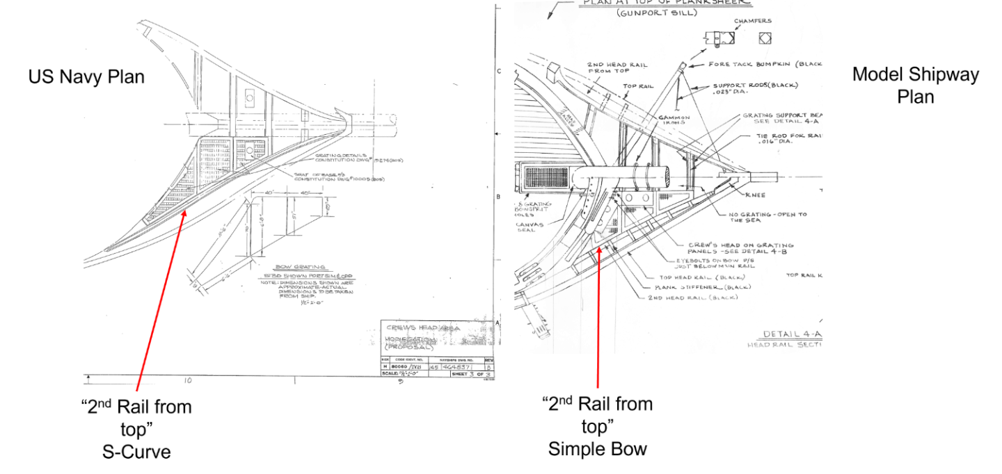
The next thing the practicum stated about the rail was, “It is not curved from side to side.” Wrong again. According to the MS plan, the second rail has a slight horizontal bow inward towards the stem, a much simpler curve than that of the 3rd rail. But I didn’t realize that until I re-read xKen’s build log (starting at post #294) of how he made his rails where he accounted for the inward bow. To double check, I looked again at the US Navy plan and saw that the bow was actually a slight S-curve. To be fair, the MS plan didn’t show the full length of the 2nd rail so you couldn’t see that it swung back slightly to form the S-curve. Unfortunately, I had already made the pair of 2nd rails. I reluctantly abandoned my first attempt and started over again this time using 1/8” layered stock (1/4” total thickness) to account for the S-curve.
-
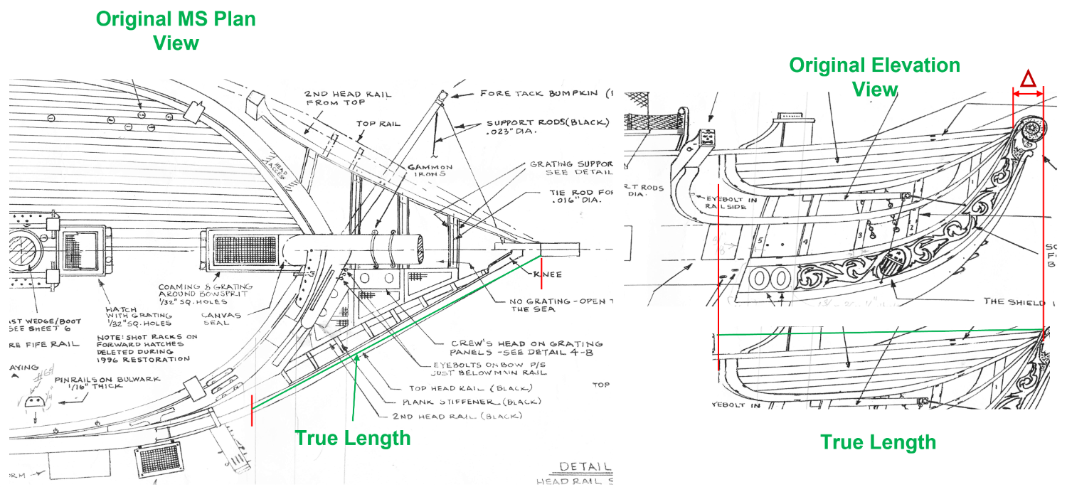
However, using the 2nd rails to dry-fit the rail supports, I soon found out that the rail supports did not fit properly between the rail and the stem. Then, reading section 8.1.4 in the practicum about installing the “2nd rail from the top” I discovered that Mr. Hunt also ran into this problem. He believed through his investigation, that the MS plans were in error for the shape of the rail supports. I then checked the US Navy plans and there were only very slight differences that I could discern, so both Mr. Hunt and I don’t know where or what error(s) occurred. His solution was to fabricate and install the 2nd rail first, then custom fabricate and fit the rail supports then, work backwards to install the 3rd rails last. Because I only glued the 3rd rail to the starboard side at just one point, it was relatively easily to pry the rail off to continue following the practicum’s solution. Going back over the practicum instructions, I noticed the practicum’s instruction for fabricating and installing the 2nd rail weren’t correct. The first error was to use the MS plan profile (elevation) view of the rail directly from the MS plan. Unfortunately, this is a foreshortened view because the rails are angled from the hull inwards towards the tip of the bow stem as indicated in the plan view. (I had this same foreshortening problem when I constructed the transom) To get the true view, that is the true length of the rails, I scanned the elevation view of the rail into my computer, using PowerPoint, rotated the image to match the angle of the rail in the plan view, then stretched the image till it matched the length shown in the plan view. Only then could I print the image with the proper rail length and make a template.

-
The practicum stated: Great, easy straight forward pieces to make…or so I thought. So, I proceeded and made the 2nd rails as instructed, complete with paint and pin stripes,

-
The next logical step seemed to be installing “3rd rail from the top. First, I used PVA glue to fasten the starboard side rail just to the underside of the cathead only. I left the stem tip end unglued to allow me some wiggle room when adding the rail supports. I anticipated that the rail supports had to be at least fitted with the rail installation. Therefore, the rail supports (port and starboard) were fabricated based on MS plan detail 4A at the same time as the 3rd rail.
-
I scanned my Mamoli plan for the Main Mast. Due to the size of the sheet, it took 3 passes. I hope it helps. IMG_20230208_0001.pdf
- 152 replies
-
- 3
-

-
- rattlesnake
- Model Shipways
- (and 1 more)
-
I would have gotten back to you sooner, but my internet connection was cut off since 1:45pm yesterday. Here are some of the diagrams from the MS Constitution plans. I hope these answer most of your questions


-
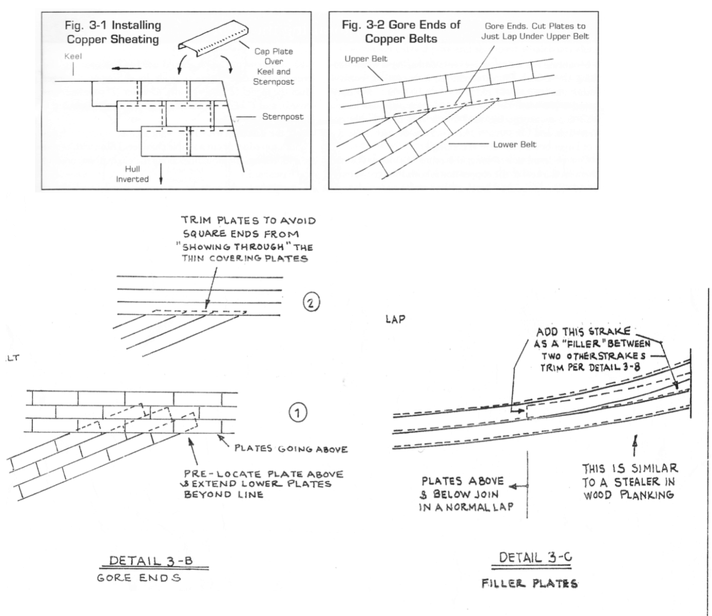
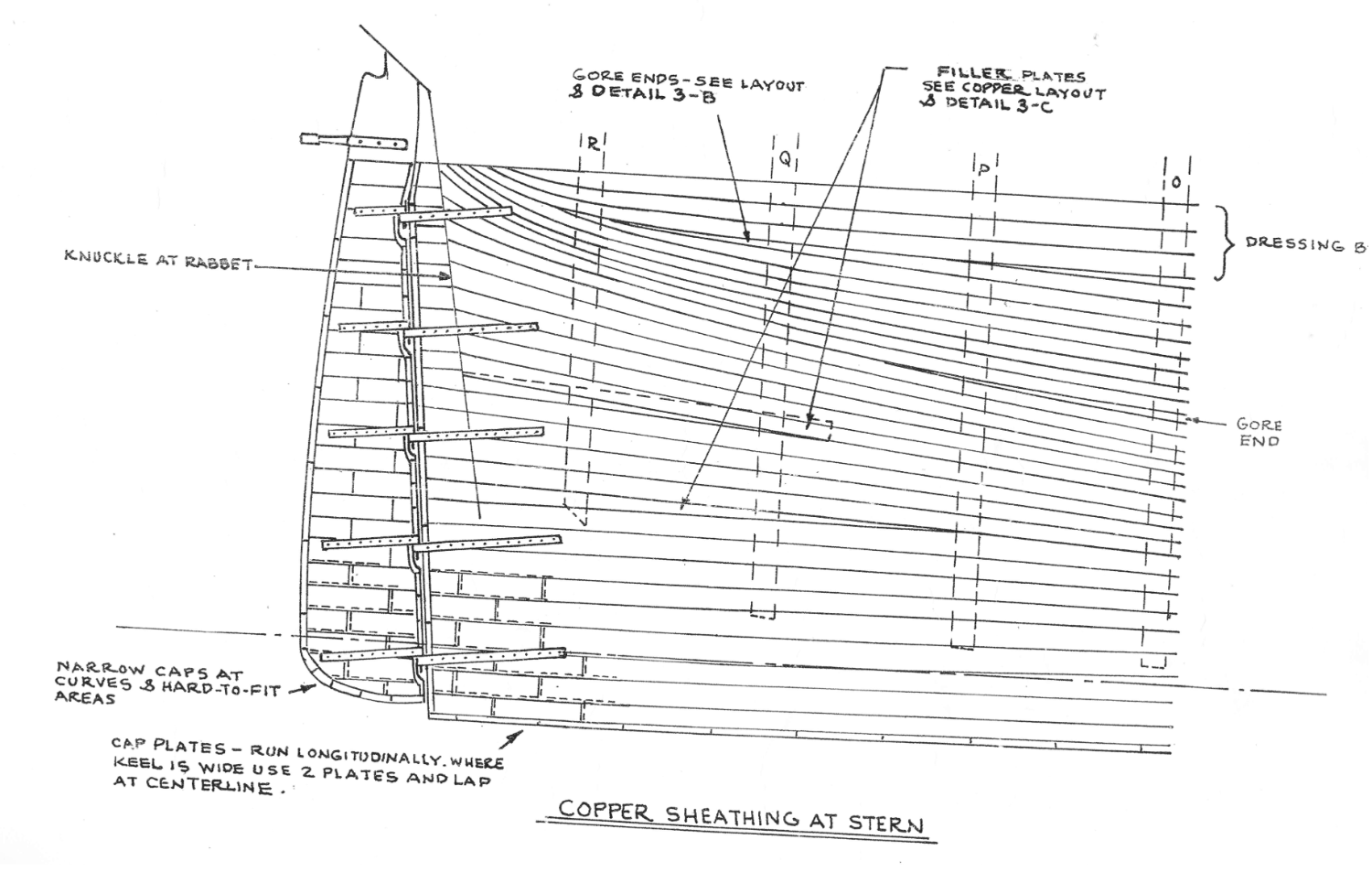
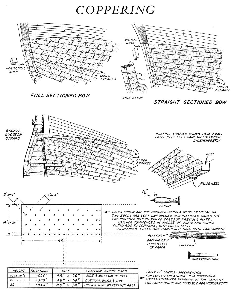
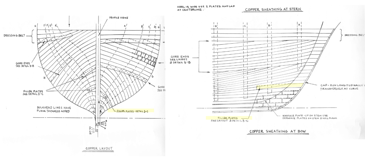
What the first diagram is try to convey is, as you apply the copper plates to the hull, you start at the stern and work your way forward and upwards overlapping the edges of of the previous aft plate as well as the plate below's top edge. The second instruction is trying to state that because the plates are applied to the hull with no tapering unlike the wooden planks which are tapered. Therefore, sharp curves are going to be created at either or both the stern and bow. In order to minimize those curves a steeler, an extra row for a short length is added. The BlueJacket instruction is telling where a steeler should be placed. At each band, you in effect start a new horizontal uncurved row. The higher band cuts off the curving from the lower band. The diagram below illustrates a coppering method. I hope this helps and not confuse you more. Jon

-
If you take a look at my build log starting at post 633, you can read why I did what I did and see the results.