-
Posts
2,641 -
Joined
-
Last visited
Content Type
Profiles
Forums
Gallery
Events
Everything posted by JSGerson
-
The pseudo bolts were applied using the same Min-Wax Polycrylic sealer used to seal the hull. A very thin layer of the sealer was applied to the appropriate hull area with a small brush. Using an X-acto knife with a fine drop of sealer on its tip, the knife, by just touching a brass “bolt head”, picks it up and transfers it to the hull. The pseudo bolts were pushed into position while the sealer was wet. The picture below shows the port side hull, gun deck level with the pseudo bolts installed. The spar deck and the complete Starboard side have yet to be done. By the time the hull is painted black, these “bolt heads” will practically disappear. So why bother? It may not be apparent to the casual observer why one model looks better than another, but I believe subconsciously the fine detail are perceived even if not overtly observed. So, the closer you look, the more you should see.
-
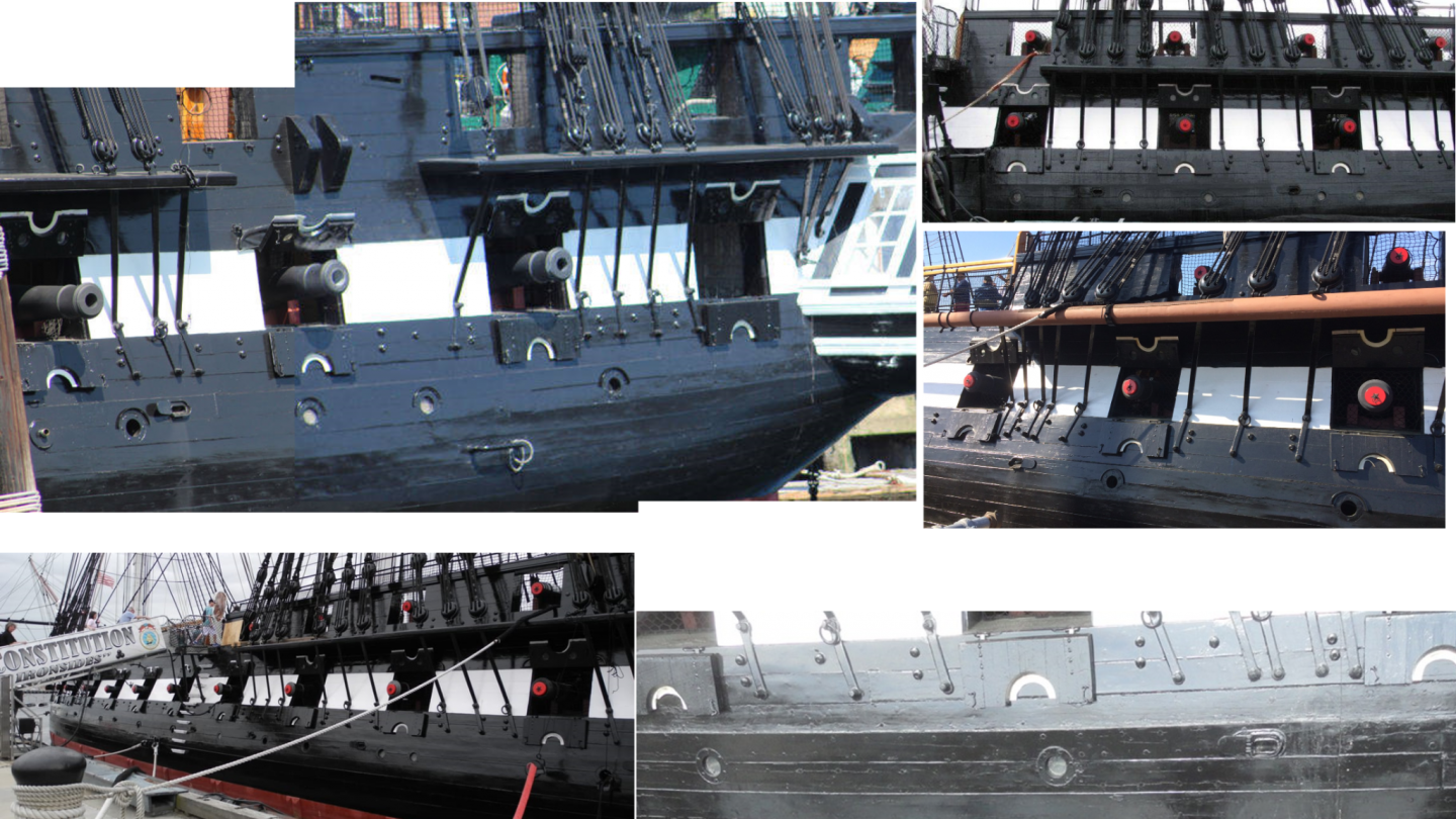
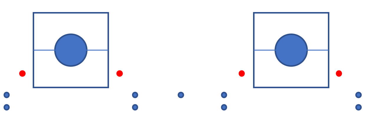
Gun Port Hull Bolts Before upper hull is painted, there are numerous accruements that I want to install first, such as scuppers, port windows, bolt heads, etc. They will all be painted black. If it can be avoided, don’t want to glue to painted surfaces. First up are the bolts that protrude from the hull around the gun ports. These are the bases of the ring bolts for the cannon rigging. These are NOT shown on the kit’s plans but can be seen on the actual ship. Based on the photos, I made a pattern to follow. The actual dimension vary slightly from gun port to gun port. Edit: I’ve added additional bolts (shown in red) to indicate that these bolts are only on the spar deck level. Why, I don’t know.
-
This is my second build using Mr. Hunt's practicum. The first time (Rattlesnake), I followed it almost religiously being a complete novice. After a while I noticed minor errors and omissions in the practicum. I believe he originally posted the practicum as he was building the model and was working with deadlines. Near the end, you could tell he was cutting corners. This was before I had discovered ModelShipWorld.com and other websites. To his credit, I could not have built that model or this one without his help and he did state that his methods were not necessarily the only/best way to do things. Therefore, on this build, I use his practicum as a skeletal framework guide. I check with other build logs and choose what I believe is the best sequence and methods for my skills. So like you, I have jumped around from section to section in his practicum using his guidance when and where needed. Right now I'm thinking of holding off painting and coppering until after I install the the stem ornamentations and quarter galleries or maybe not, I haven't decided. I do want to paint the upper hull before I work on the gun deck interior. First I have to touch up the spar deck hull walls a bit better.
-
Beautifully done. Don't feel bad about the gun port positioning error, I did something similar on the spar deck gun ports when I was framing them out. It is easy to get confused when looking a bare framing. You can lose sight as to which side of the frame the opening is suppose to be. You and I are at the point in planking and I've got to say yours looks a whole lot nicer even though mine took a whole more time. At this point I suspect I'll be following you. I still have to complete the gun deck interior, a feature I elected to add, which you don't have to deal with.
-
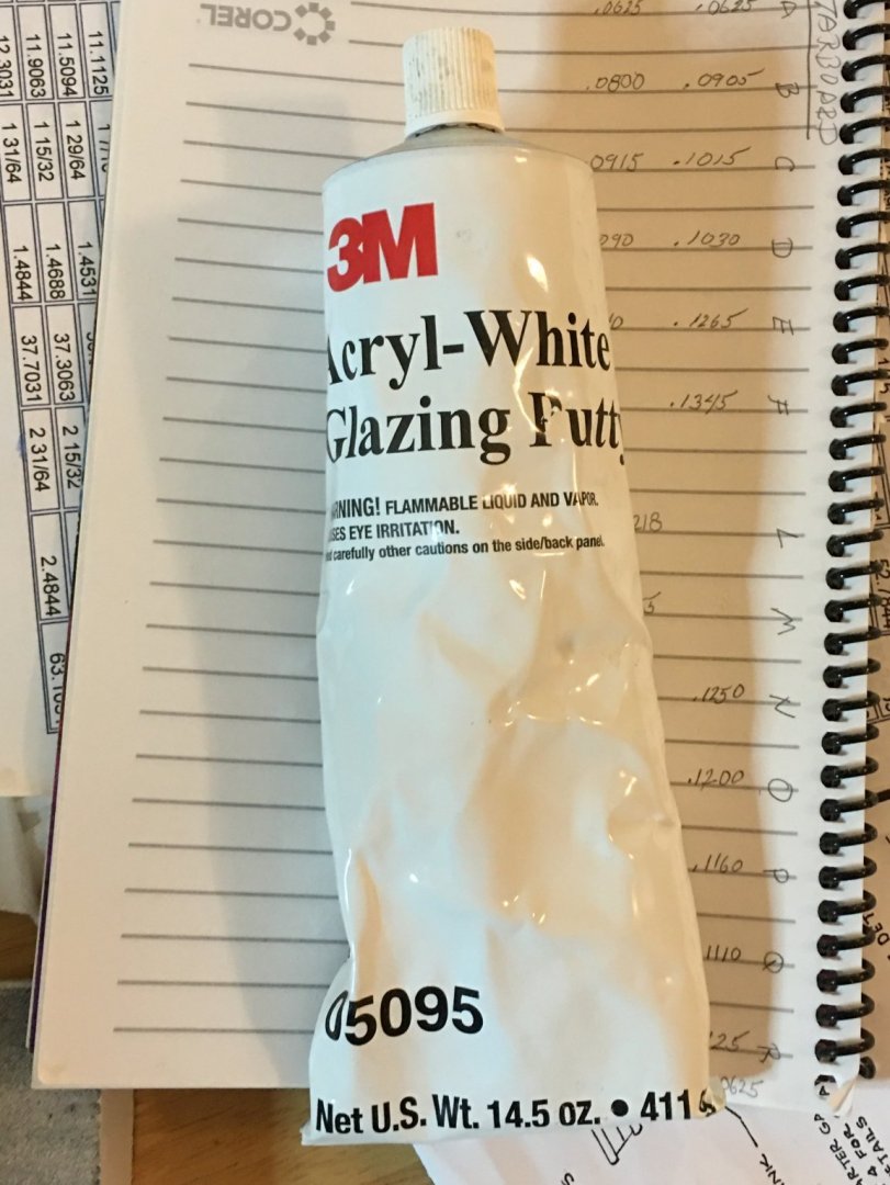
The stuff sets up in about 30 minutes, but I would wait as a minimum of four or more hours just to be sure. It becomes hard but easy to sand. Then the areas were scraped and sanded. Because the putty shrinks slightly upon hardening, I used more than one coat in many areas and repeated the process and repeated again till satisfied. Here are the instruments of removal: scrapers, sanding sticks, files, and a sponge sanding block.
-
The last hull plank has been installed. As I’ve mentioned before, this is only my second hull planking and it’s a lot better than my first (Rattlesnake). Here at least I think I knew what had to done. I came close but there was a bit more stealer joints used than I had planned for. A fine model builder and kit designer, Chuck Passaro once said that if you plan the planks right, you won’t need any stealers. Well, I needed them. That’s all a moot point because the hull has to be sanded, touched up to fill some voids, sealed, and prepped for copper plating, and painting, which will cover the planking imperfections from the critical eye.
-
No problem posting a link to my log. I kinda wish you would maintain your log. Seeing how other builders deal with problems and the solutions they come up with is the main reason I read everyone else's logs. If it's real time (as opposed to milestones), we the readers, can offer immediate solutions or even better, prevent you from making mistakes. I've learn so much that way. Still, I look forward to all your future posts.
-
Nice recovery on the planking; it's looking great now. What's better, is that the black paint and copper plating will completely cover up the planking lines and no one will ever know. I noticed that the bottom of the wale has not been blended into hull yet. Were you planning on doing that after the hull planking is completed? I did mine as I was it stalling it. My hull is almost fully planked. I've got about three rows left on the starboard side.
-
You are moving right along, much faster than me. Looking at your third picture (the full hull upside down), it appeared to me that your strakes have a wave, dipping towards the keel and then rising again. You might want to verify the width calculations of you planks so that when you get to the keel, it's nice and straight. As I was planking the belts on my model, I recalculated the plank widths each time I started a new belt. They did change a bit due to how well I made the planks and installed them.
-
I’m just a little ahead of you in my planking attempt of my Conny. I didn’t have much luck (or skill?) using the proportional dividers. I could never get them lock with the center screw knob once I took a measurement. The arms moved too easily. I could not convince myself that proportional measurement was accurate, but that’s another story. Instead, I worked with the five-plank band as described by Mr. Hunt, temporarily laying the fifth plank and marking the line it created as it wrapped around the hull. Then at each bulkhead I measured the distance from the last plank laid in the previous band to the line and divide by 5 and recorded the width. I did this for each bulkhead. On each plank, I marked where the bulkhead was and using a micrometer and sandpaper, each plank was sanded to its proper width at every bulkhead position. The dividers would have made it much easier, but I just couldn’t get a consistent result. I will be glad when this portion is finished. Or course there is the copper plating, the cannons and their rigging… 8-)
-
Beautiful model and case. Mine should look as good when I'm done. Out of curiosity, what are the dimension of the case?
- 55 replies
-
- constitution
- model shipways
-
(and 1 more)
Tagged with:
-
Looking very nice. You might want to consider looking at Ken Foran's Constitution build. He is a professional model builder and kit designer. He created the Model Shipways cross-section kit of the Constitution with very impressive instructions. With your skills, you should be able to do many of his techniques with ease.
About us
Modelshipworld - Advancing Ship Modeling through Research
SSL Secured
Your security is important for us so this Website is SSL-Secured
NRG Mailing Address
Nautical Research Guild
237 South Lincoln Street
Westmont IL, 60559-1917
Model Ship World ® and the MSW logo are Registered Trademarks, and belong to the Nautical Research Guild (United States Patent and Trademark Office: No. 6,929,264 & No. 6,929,274, registered Dec. 20, 2022)
Helpful Links
About the NRG
If you enjoy building ship models that are historically accurate as well as beautiful, then The Nautical Research Guild (NRG) is just right for you.
The Guild is a non-profit educational organization whose mission is to “Advance Ship Modeling Through Research”. We provide support to our members in their efforts to raise the quality of their model ships.
The Nautical Research Guild has published our world-renowned quarterly magazine, The Nautical Research Journal, since 1955. The pages of the Journal are full of articles by accomplished ship modelers who show you how they create those exquisite details on their models, and by maritime historians who show you the correct details to build. The Journal is available in both print and digital editions. Go to the NRG web site (www.thenrg.org) to download a complimentary digital copy of the Journal. The NRG also publishes plan sets, books and compilations of back issues of the Journal and the former Ships in Scale and Model Ship Builder magazines.


