HOLIDAY DONATION DRIVE - SUPPORT MSW - DO YOUR PART TO KEEP THIS GREAT FORUM GOING! (Only 75 donations so far out of 49,000 members - C'mon guys!)
×


JSGerson
-
Posts
2,623 -
Joined
-
Last visited
Content Type
Profiles
Forums
Gallery
Events
Everything posted by JSGerson
-

Looking for Rattlesnake instructions
JSGerson replied to rattle snake corvette's topic in Wood ship model kits
I also built the Mamoli Rattlesnake. The sheet plans have English, French, German and Italian translations on them. Some things that are not translated can be translated using Google or equivalent. I can provide you with two documents that may help you: Mamoli Parts List Translation which I created Reading-Decoding Mamoli Rigging Charts by Bill Edgin I hope these help Jon Mamoli List Translations.docx Reading-Decoding Mamoli Rigging Charts.docx -
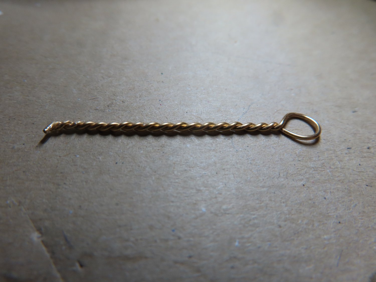
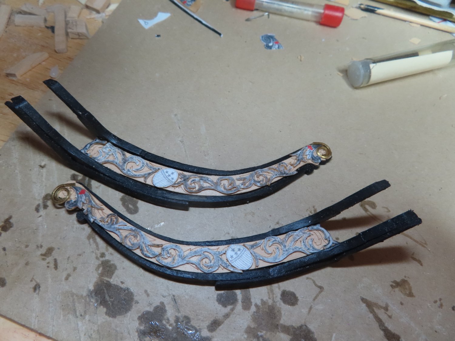
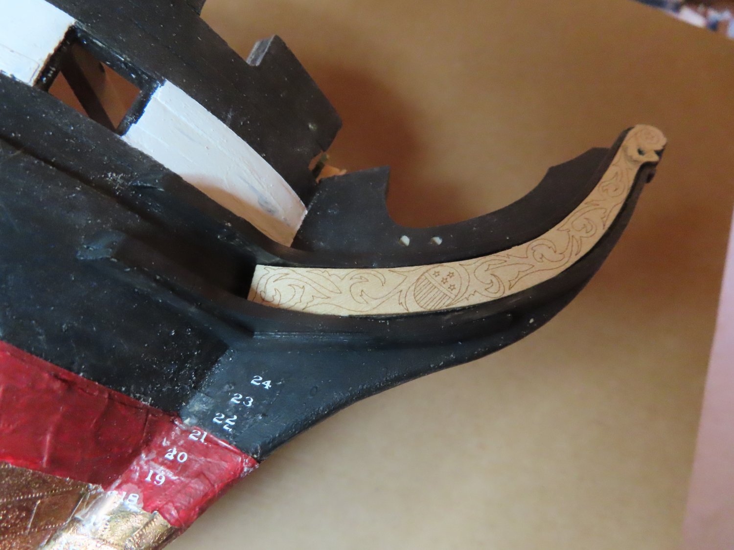
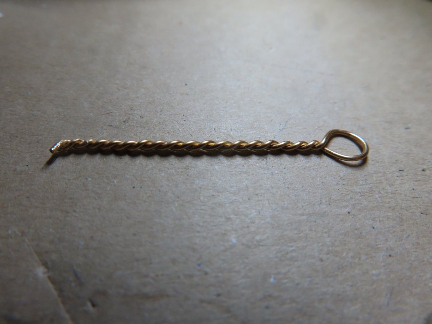
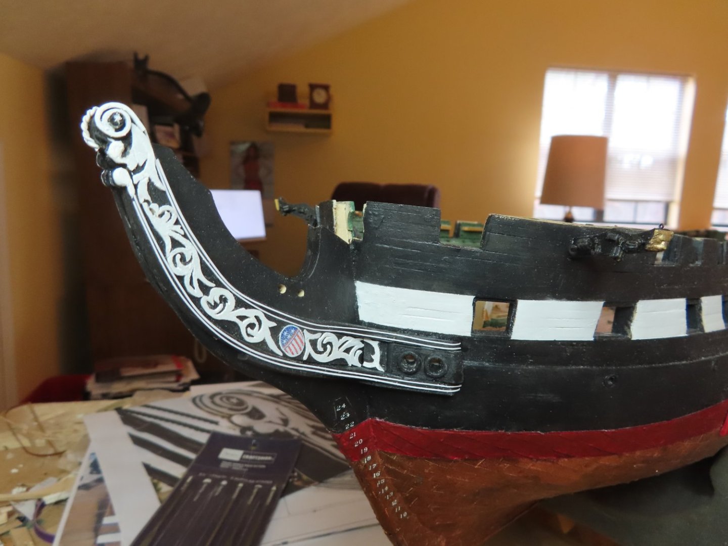
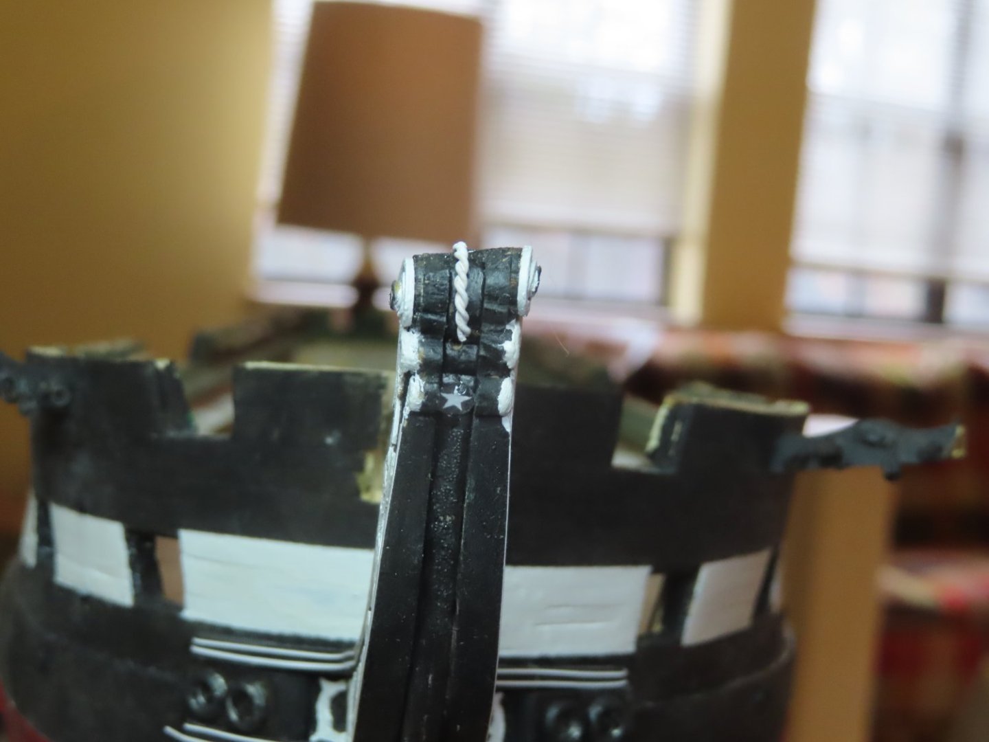
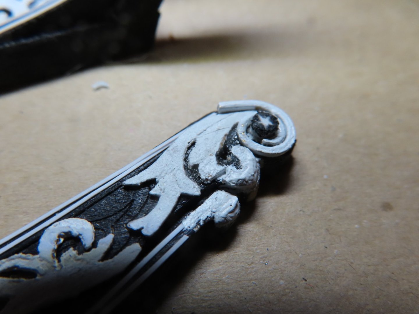
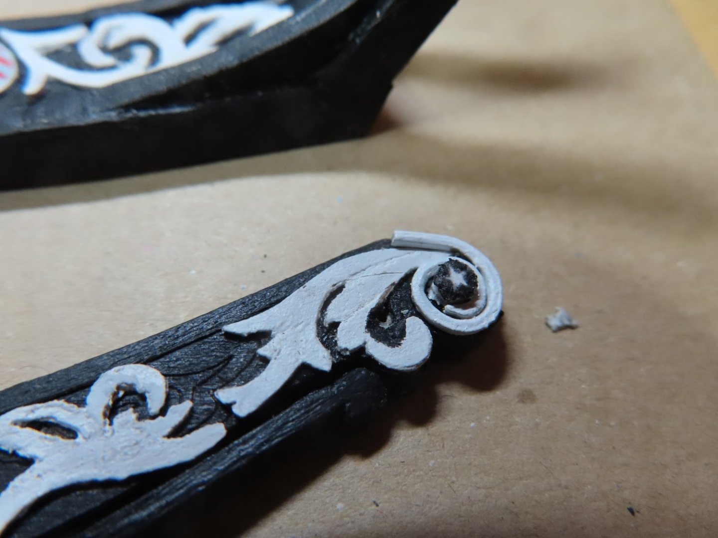
Finally, the trailboards where glued into place. Then the hawsers were painted black and glued into position. Using my normal cordless drill with an 1/8” bit, the two openings in each howser were drill out into the interior of the model so that the future anchor chain and rope can pass through. The final touches were the white star and the braid on the front of the fiddlehead. The braid was made by twisting two strands of brass wire tightly, and then cutting the resulting piece to length. Two holes were drilled into the fiddlehead for each end of the braid to be inserted. Before the insertion, the braid was paint white. I should note that the thickness of my fiddlehead turned out to be thicker than the US Nay plans call for. Had I been aware much earlier on, the stem would have been tapered. But it is what it is.

-
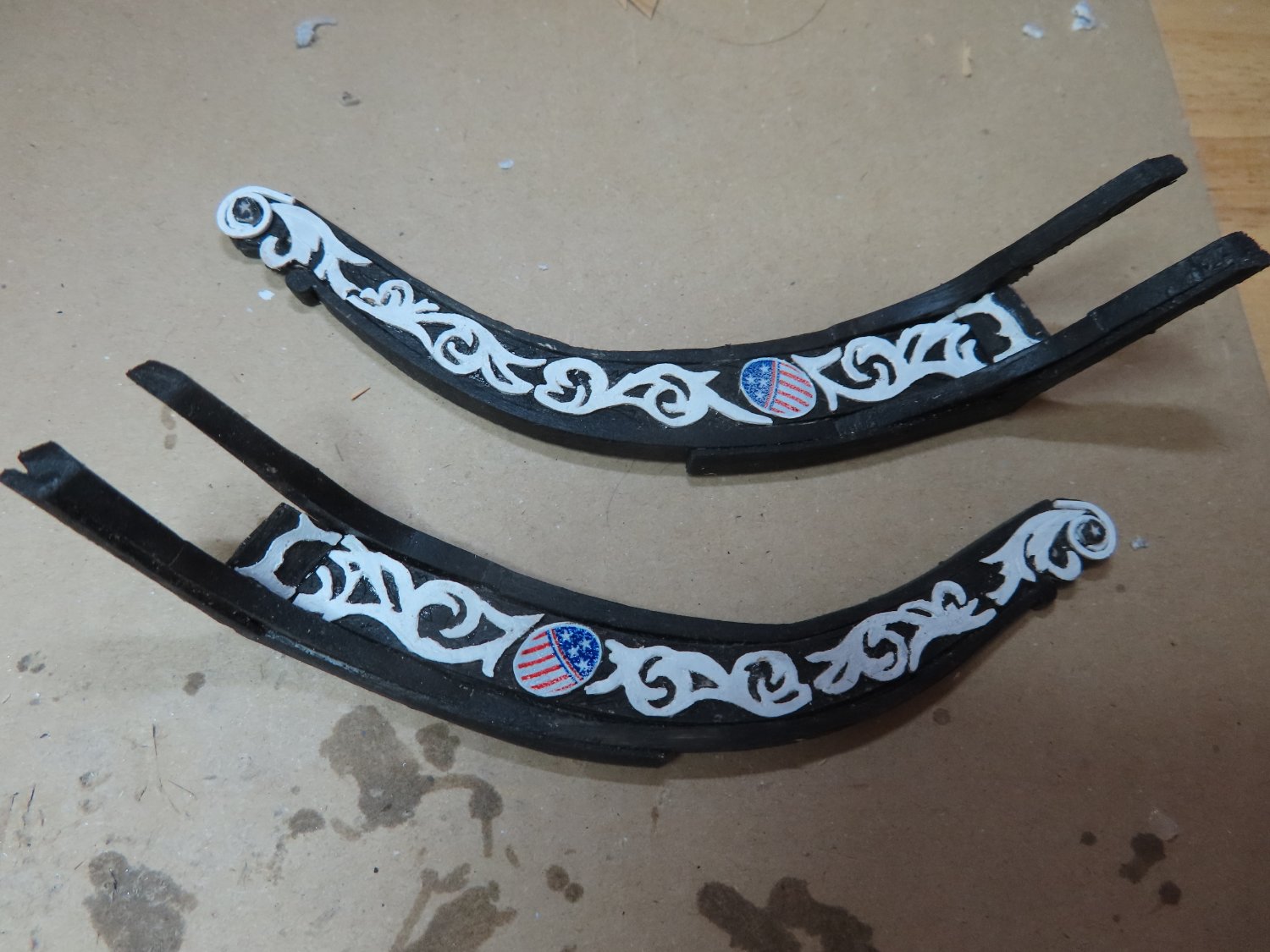
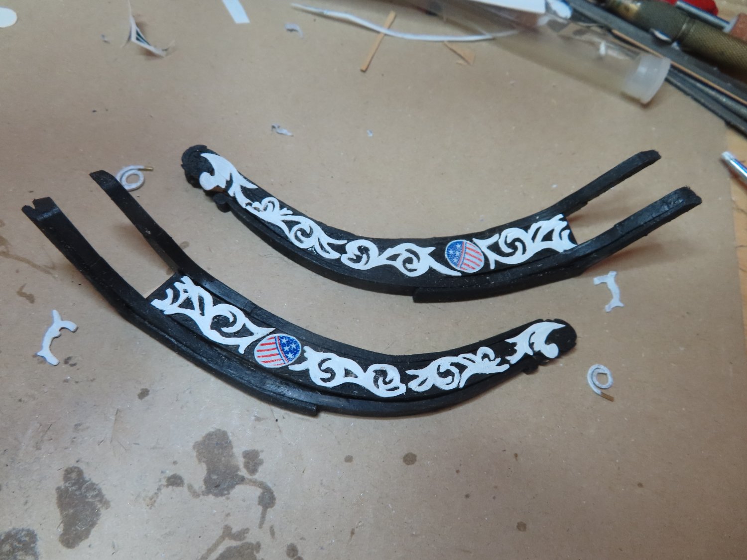
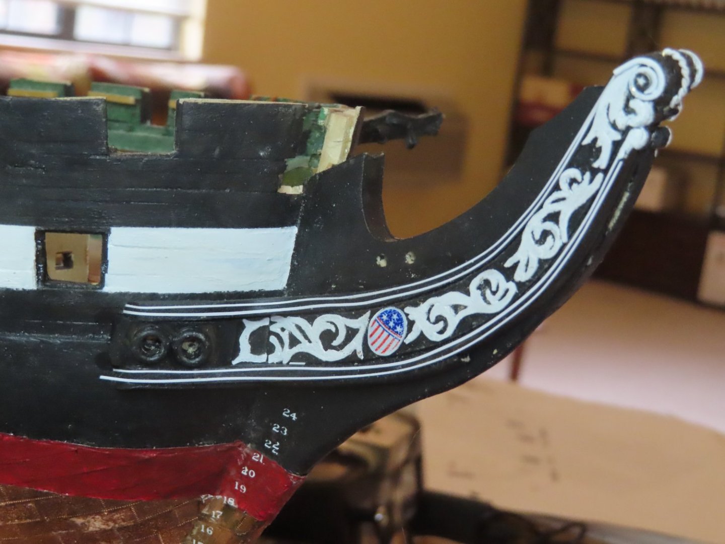
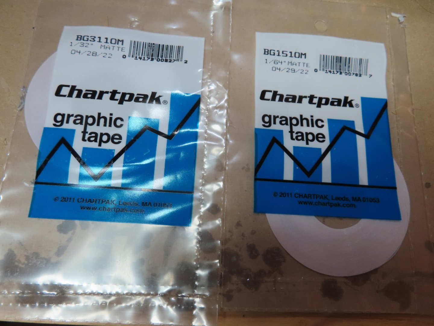
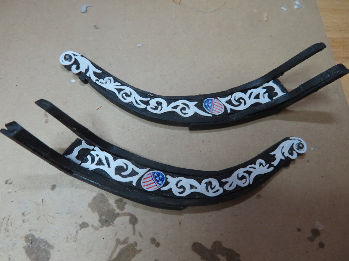
Based on kmart’s idea (post 146), of the white architectural pinstriping tape, it is a lot easier to use than trying to work with very fragile narrow wood strip which must bend to the contour of the rails. 1/64” and 1/32” tape was purchased for the pinstriping of the bow. Only the 1/64” tape was used to pinstripe the trailboard. Additional white paint was used on the scroll work at the tip of the fiddlehead. Lucky, you can’t see all the imperfections that you do see in the magnified images.

-
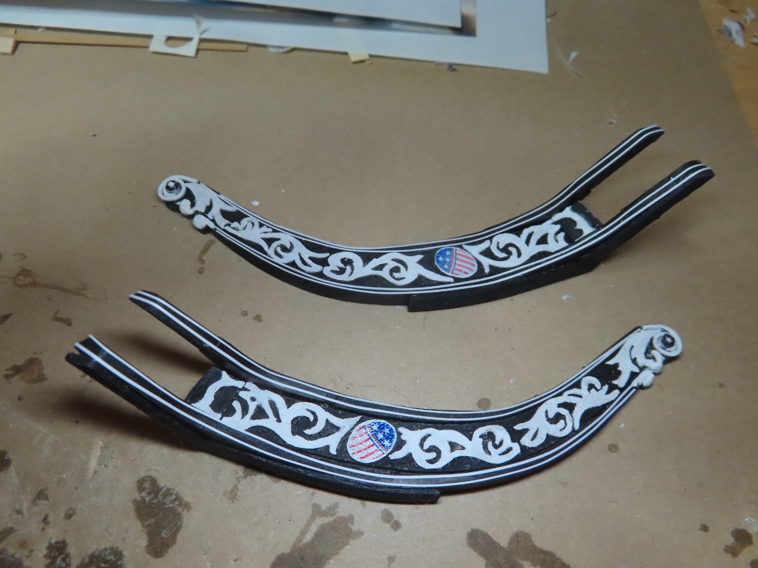
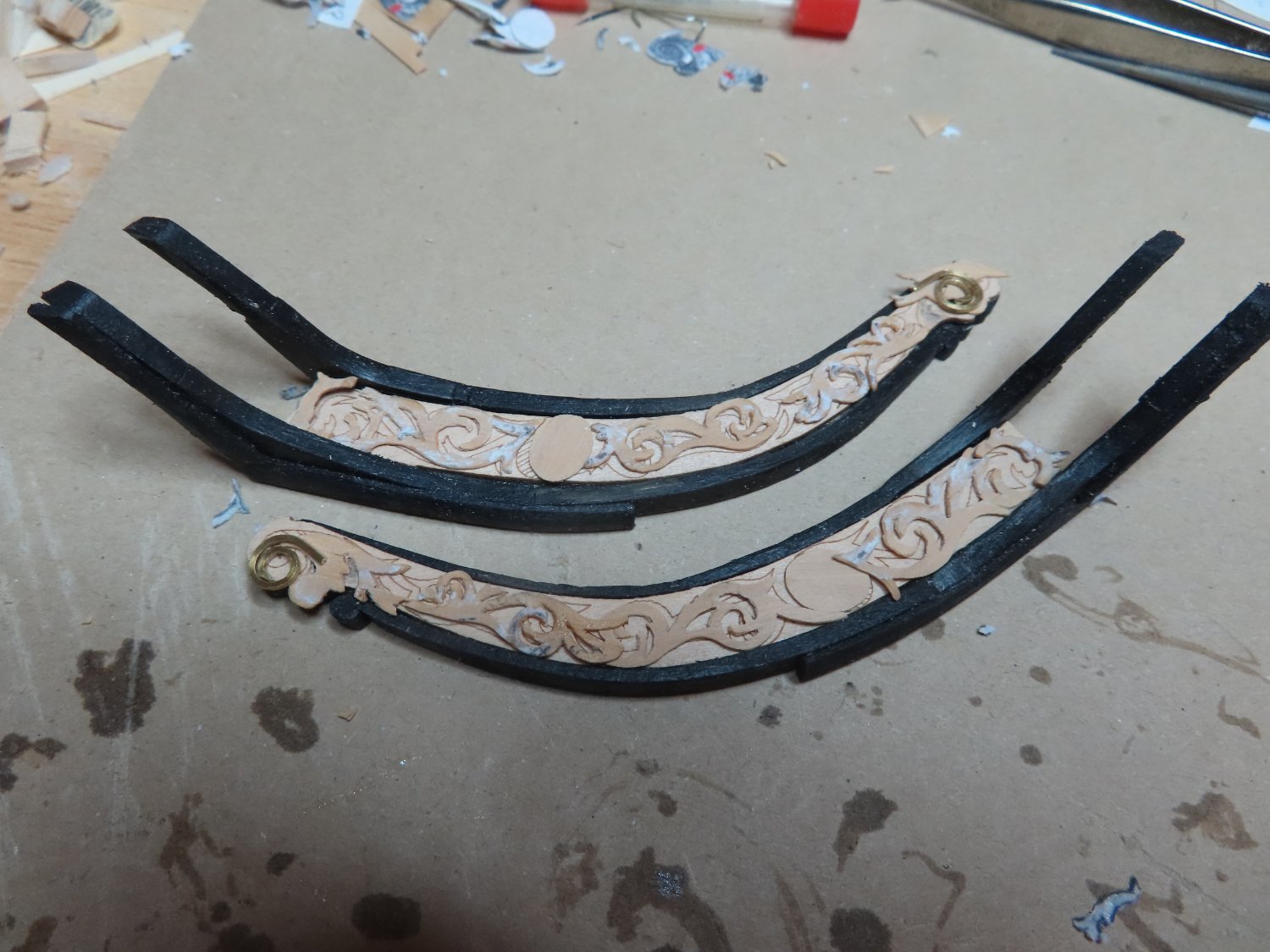
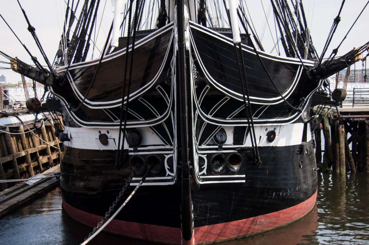
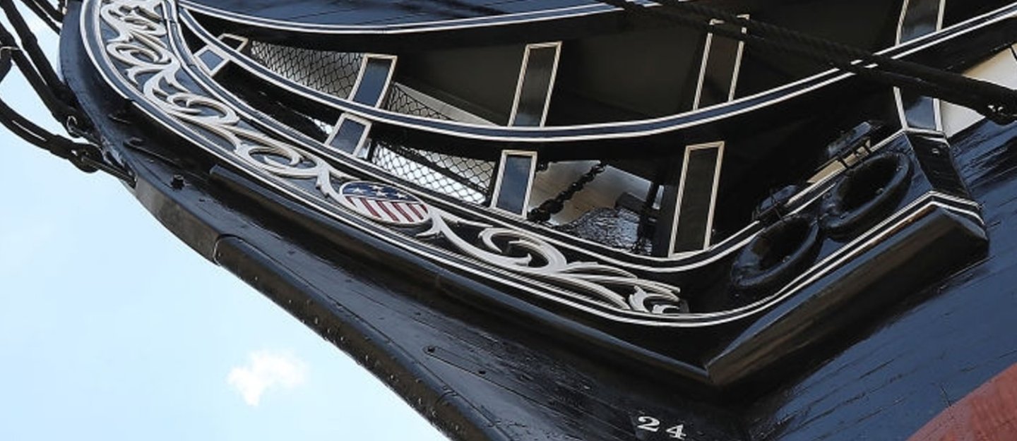
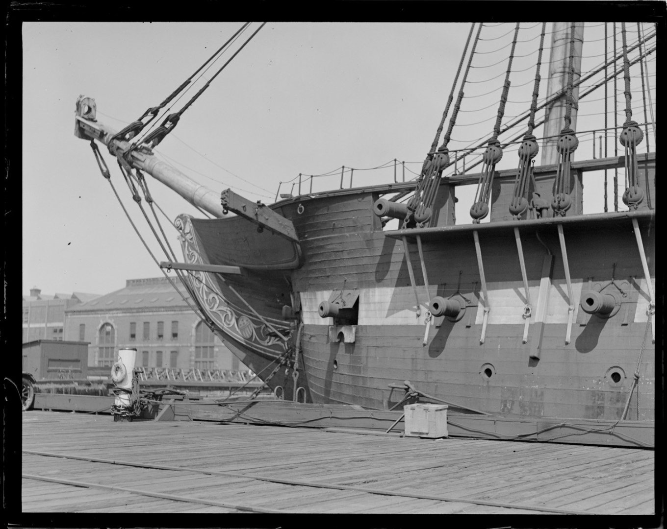
The scroll boards spirals and stars were glued to the scroll board. The last element of the scroll board is the carved section right where the scroll board meets the hull as you can see is images below of the actual ship. This piece is actually attached to the hull and the scroll board and not just on the scroll board as the kit and practicum would have you install it. Therefore, that’s the way I fabricated and installed it. The short piece is mounted on a piece of 1/32” piece of wood. With one end one the scroll board and the other to be attached to the hull.
-
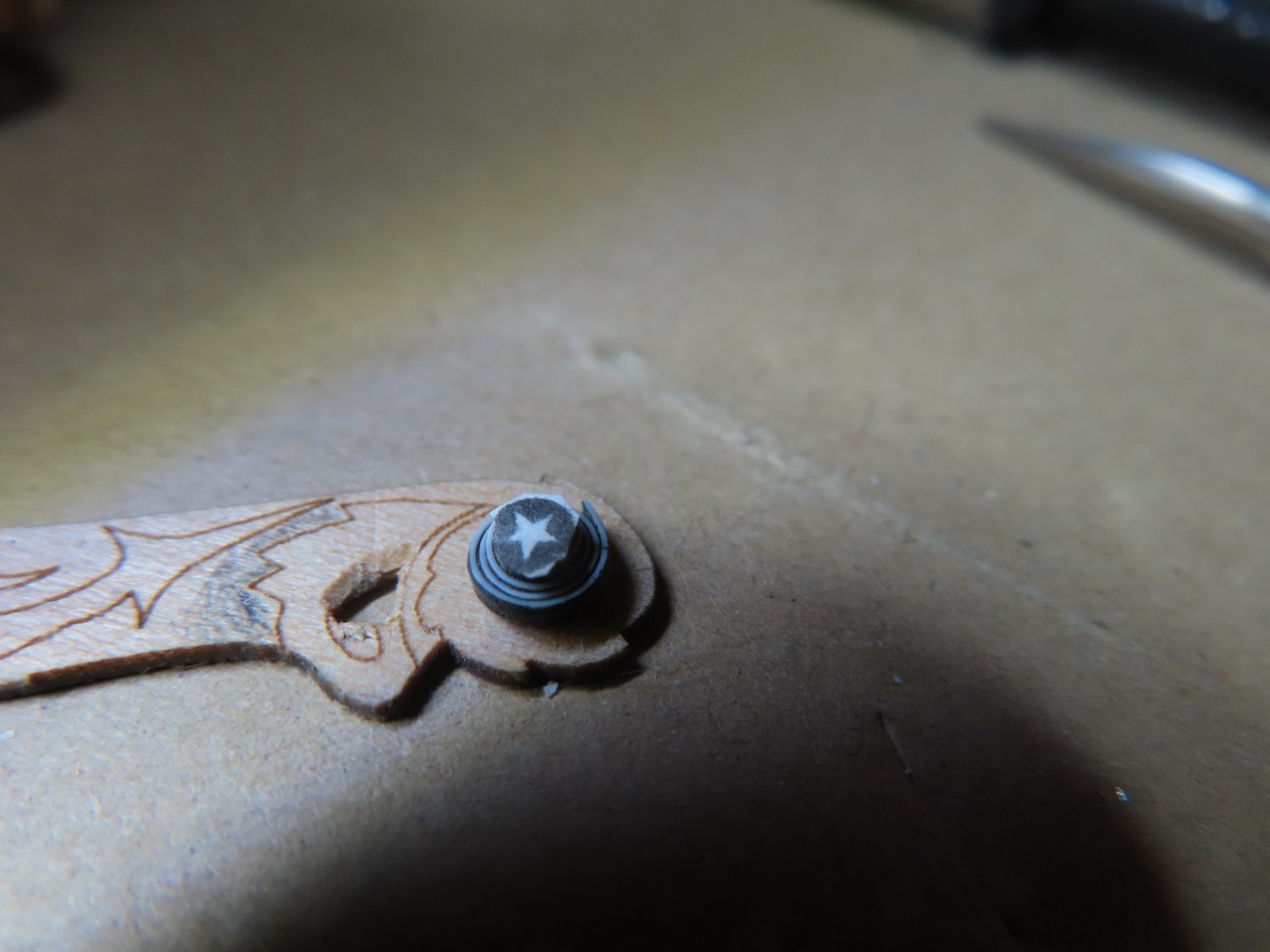
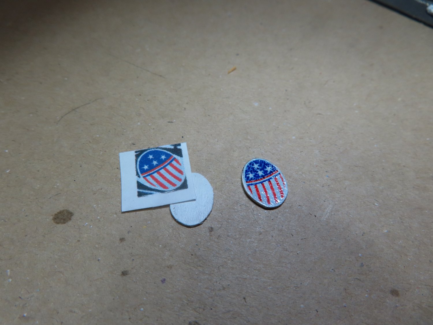
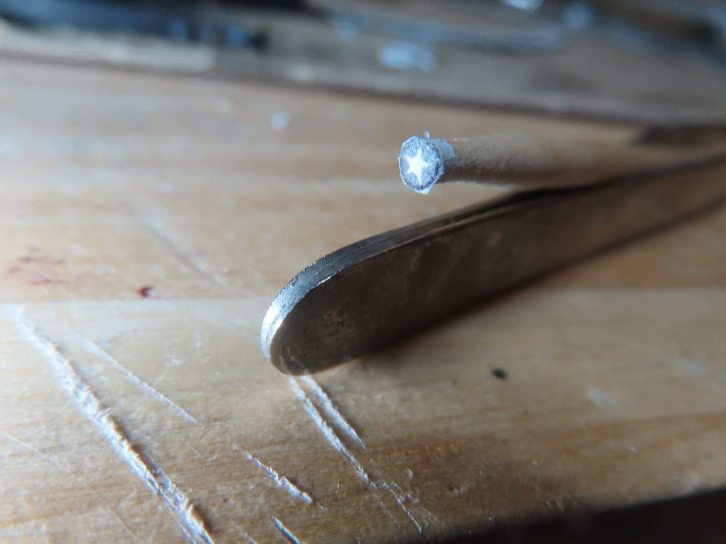
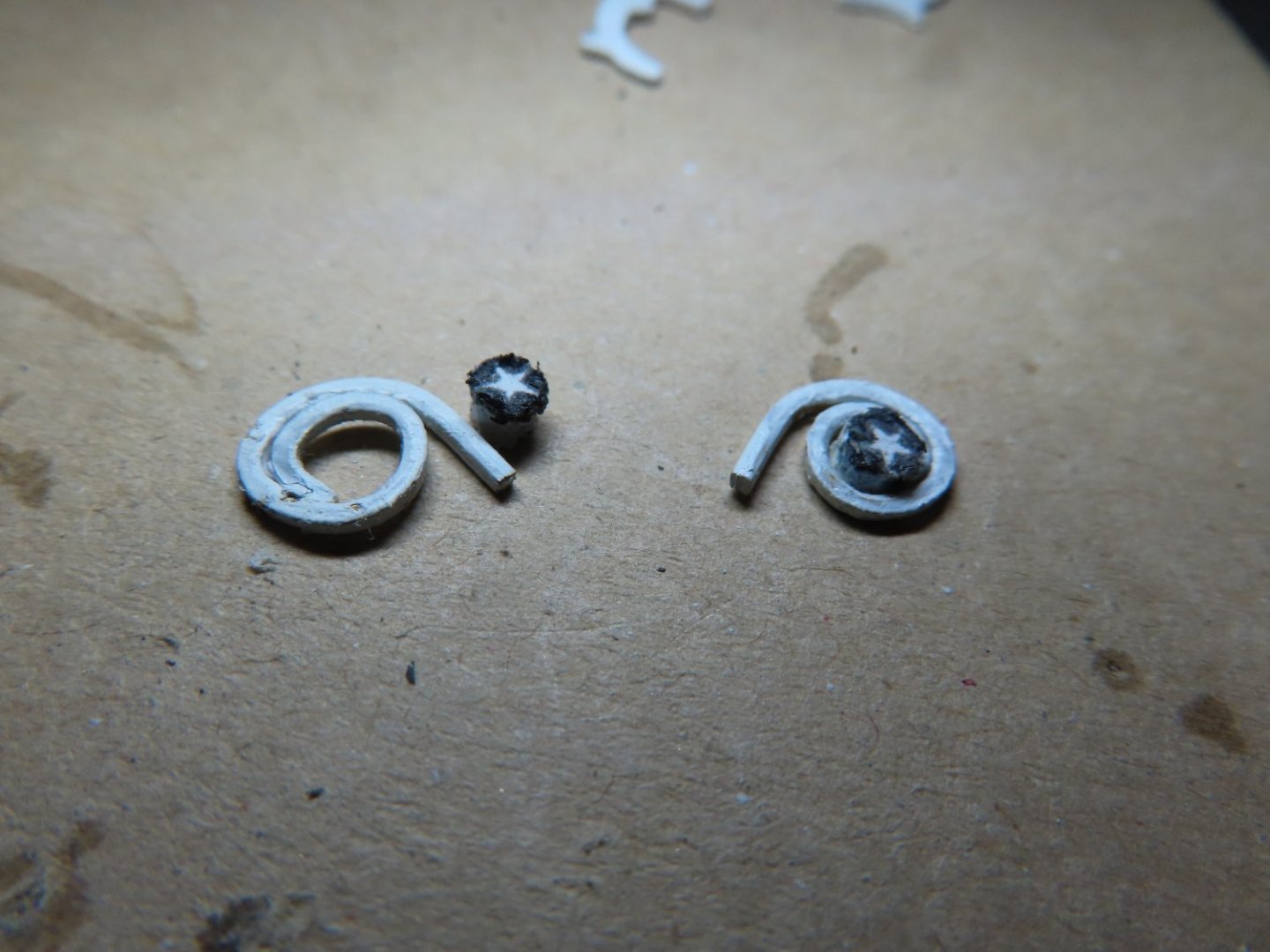
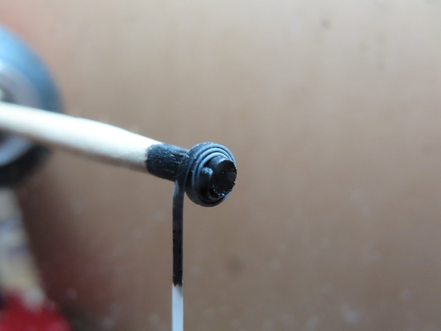
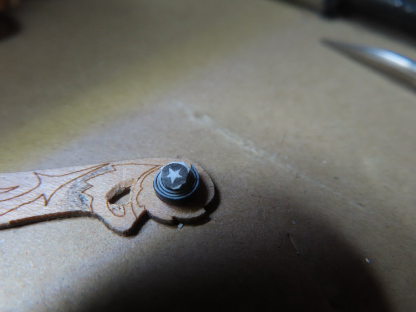
I also felt that the practicum’s styrene fiddlehead star was too big, another reason I didn’t follow the practicum for this detail. The star was made on the computer and printed on white paper. I thought about a decal, but the whole circle is only 3/32” in diameter and it had to be applied to a 3/32” diameter dowel. Because the star is white, the end of the dowel would have to be white, and the decal would provide the black markings to render the star image. Maneuvering a decal that small was going to be a bitch, so I chose to glue the paper to the dowel. It would then be cut off to a final height of about 5/64”. The images below show the brass spiral painted white (still needs a bit of touchup) and the paper white star and black background loosely in position for demonstration purposes.
-
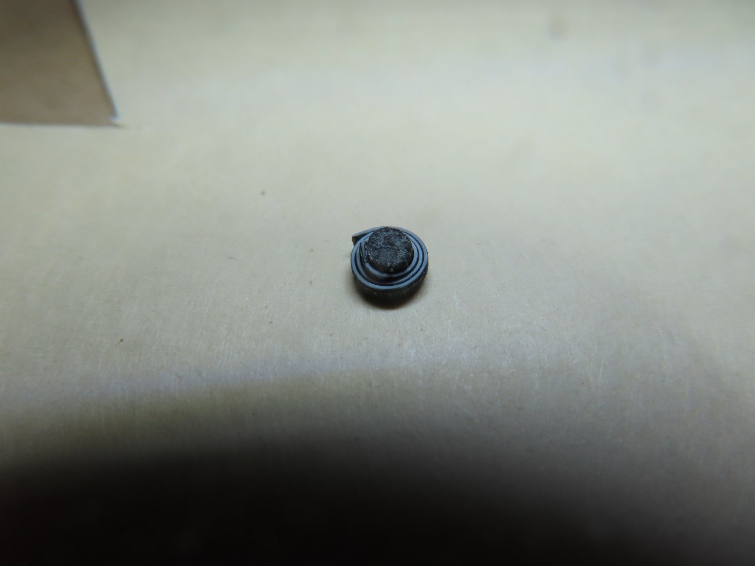
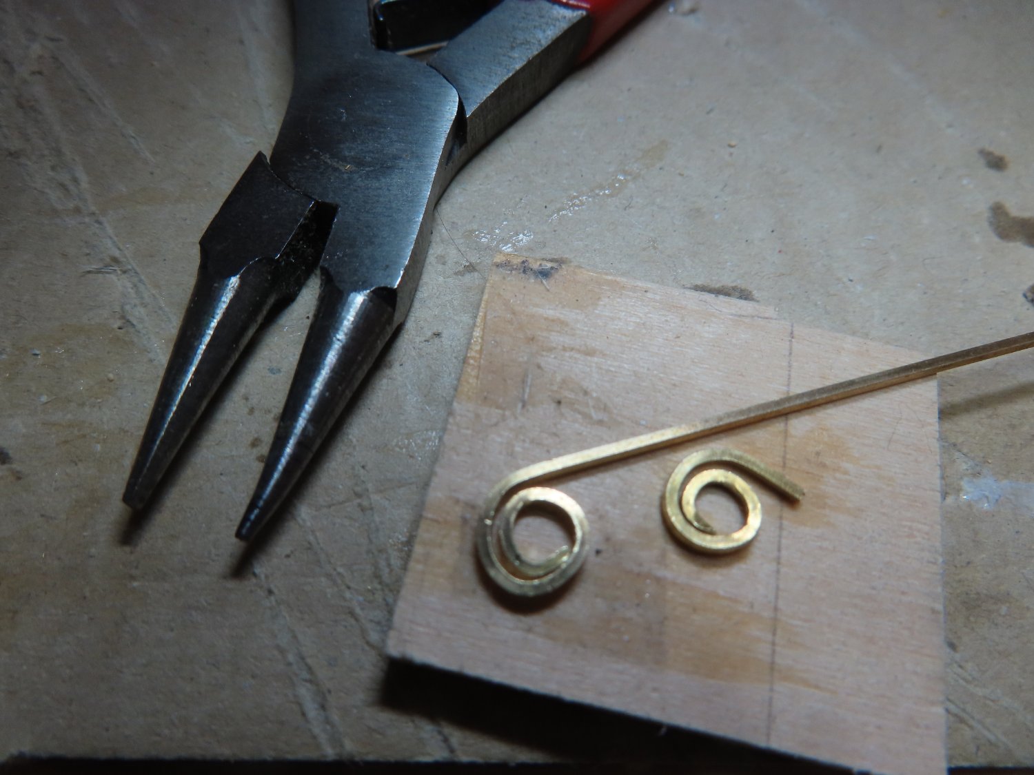
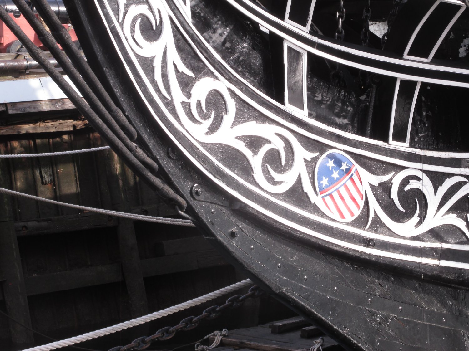
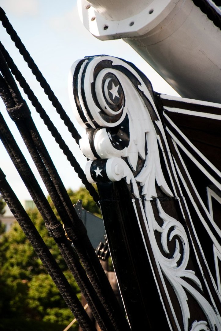
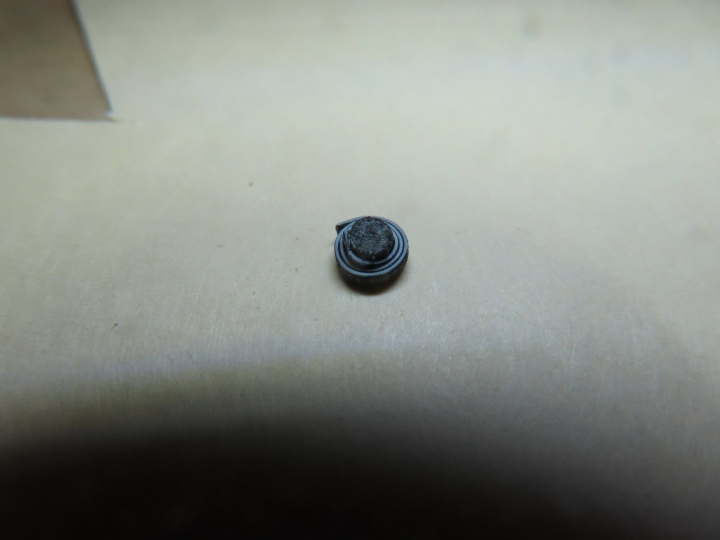
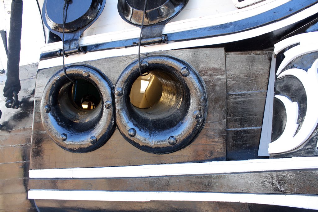
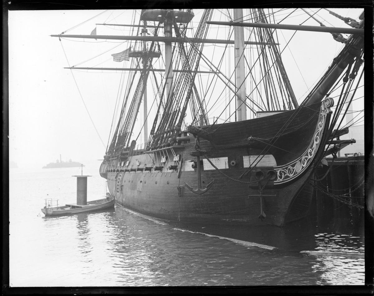
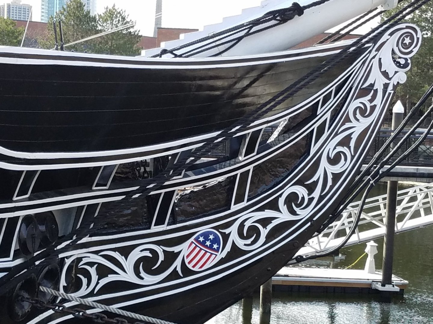
That was the easy part. The fiddlehead was a bit more complicated. If you look at the actual ship’s fiddlehead below, it is a highly complex sculpture. I made several attempts to simulate the fiddlehead spiral using wood, styrene, and finally brass. I finally I settled on 1/32” x 1/32” brass rod. It could be bent into a very tight spiral without breaking, it was the right thickness, and I could make spiral open so the black background would show through. The last two images are the first rough shapes. You can see that I left a round opening for the central white star in a black circle.


-
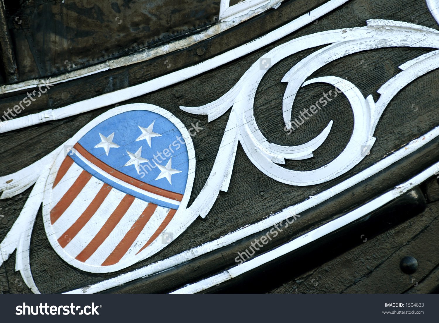
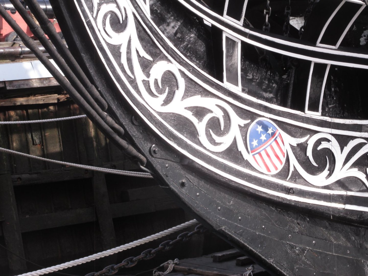
The colored shield image was provided for a decal in the practicum, but good as they were, I decided to see if I couldn’t make my own from an actual image (shown below). The colors of this image were weather faded, so I had to use the computer to make the colors pristine. The image was cropped and reduced to scale size to create a decal. The wood shield piece had to be painted totally white before the decal could be applied.


-
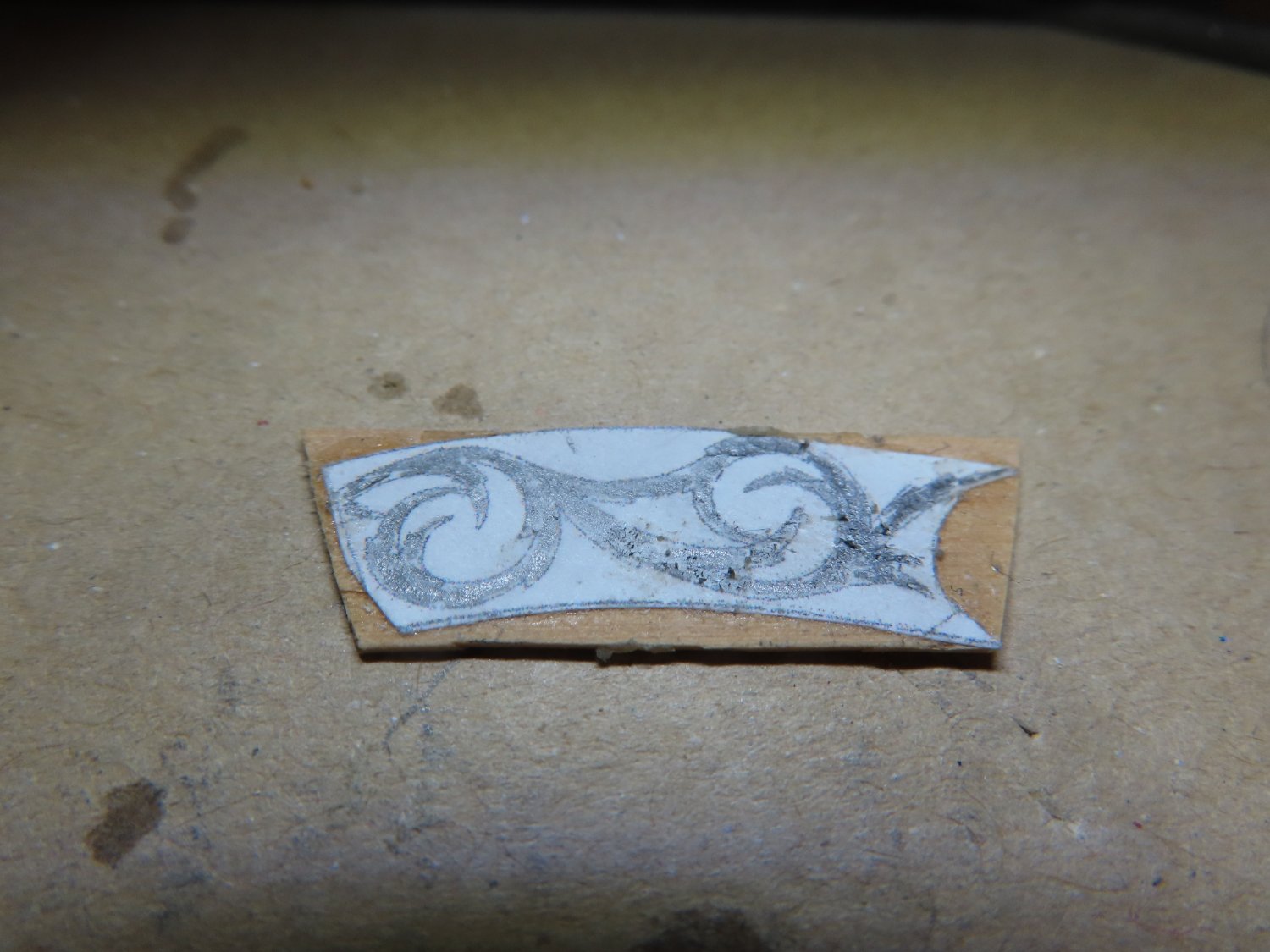
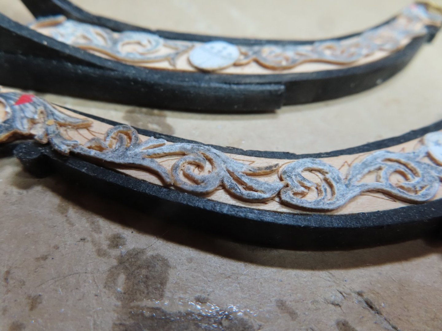
Being my anal self, instead of using the kit supplied pattern for the carvings, I used the US Navy’s plans. 27498 - Billet Head sh1 30155001 - Bow Scroll Board I cut the paper patterns of the scroll board and rubber cemented them onto the 1/64” boxwood. So, I wouldn’t lose my way, I shaded in the scroll work with a pencil. Then using very, very fine etching bits (cone, ball, and rod) in my rotary tool, I cut the patterns out of the wood. All the unshaded areas were removed. The images below show the process and are just rough dry fits.


-
What’s been keeping me up all night is trying to figure out how to fabricate the carvings on the scroll board. I studied how other builders performed this task and it varied from using styrene (practicum), just painting the design, building up solder on a brass plate and carving the soft solder, etc. The carvings are basically flat and slightly proud of the base surface, so they do have some 3D dimension, which for me ruled out just painting the designs. Making the carvings out styrene as the practicum shows, bothered me because it was not wood, it’s too thick for the scale, and the styrene becomes very delicate when attempting to make fine detail cuts. xKen (post 322), who made his carvings out of brass plate and solder did a beautiful job, but the result I felt was out of scale in height above the base. I felt it was too thick. So, I finally chose 1/64” thick boxwood for most of the carvings. The photo below shows the flatness of the carvings, and any surface carvings are minimal, and shallow. At this scale they would be lost when the carvings are painted.
-
It’s been almost 2 months since my last update. I’ve been busy working on the model, but that’s not to say I accomplished much.in the first month. Again, with the false starts, restarts, hesitations, and wasting time, I did manage to fabricate and install the “support shelf” to the underside of the bottom trailboard rail. The rails themselves still were not installed at this time so I would have more freedom to work on the scroll board off ship.

-
Very nice clean look. Well done. Jon
-
Hi KMart, sorry I didn't get back to you earlier but I was out of town for a week visiting my sister for Thanksgiving and today I'm catching up on emails and such. The cathead figurine I bought is about 1/4" square which was based on the the laser cut cathead supplied by the kit and verified by the US Navy plans. The US Navy plans show the face of the "cat" to be 15 1/2" wide or 0.202" at 1:76.8 scale. At 1:75 scale, it's 0.206", so 1:75 is the scale you need to buy. Sorry about the price change. Jon
-
It's a mutual admiration society between us because I did take your idea for the architectural tape and bought some to do my pin striping which by the way is more accurate than using 1/32" styrene or wood. The MS plans shows the detail as 1/32" half rounds strips or about 2 1/2" full scale proud of the rail. But if you look at all the current images, those strips are flat and hardly rise above the rail surface. Good call. I'm still trying to figure how to form the fiddle head with the star a bit more realistic than what shows on the kit's laser cut part. Yours is spot on to what the kit shows. I'm a bit anal and am trying to do a bit more. So far, not much luck. If I fail, I'll try to make mine, look like yours. I'll be taking a break this week, visiting with my sister for Thanksgiving in Windsor Connecticut, a colonial section of Hartford. Have a good holiday. Jon
-
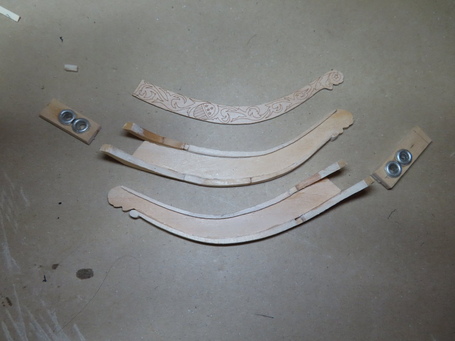
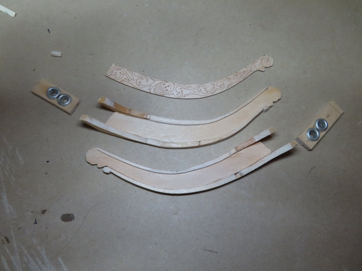
After numerous false starts, restarts, hesitations, and wasting time, I got the pieces partially glued together all the while measuring, remeasuring, checking and rechecking and still I had to do a bit of fudging to get it to this stage. I discovered from photos of the underside of the trailboard taken during the 2015-17 restoration, there was a “support shelf” (my term) that is not shown on the kit plans or installed by anyone else that I could find sufficient details on. I did not find a US Navy plan of the trailboard rail construction. The last image shows two pieces of 3/64” x 3/16” basswood stock per side that will be used to create the “support shelf.”
-
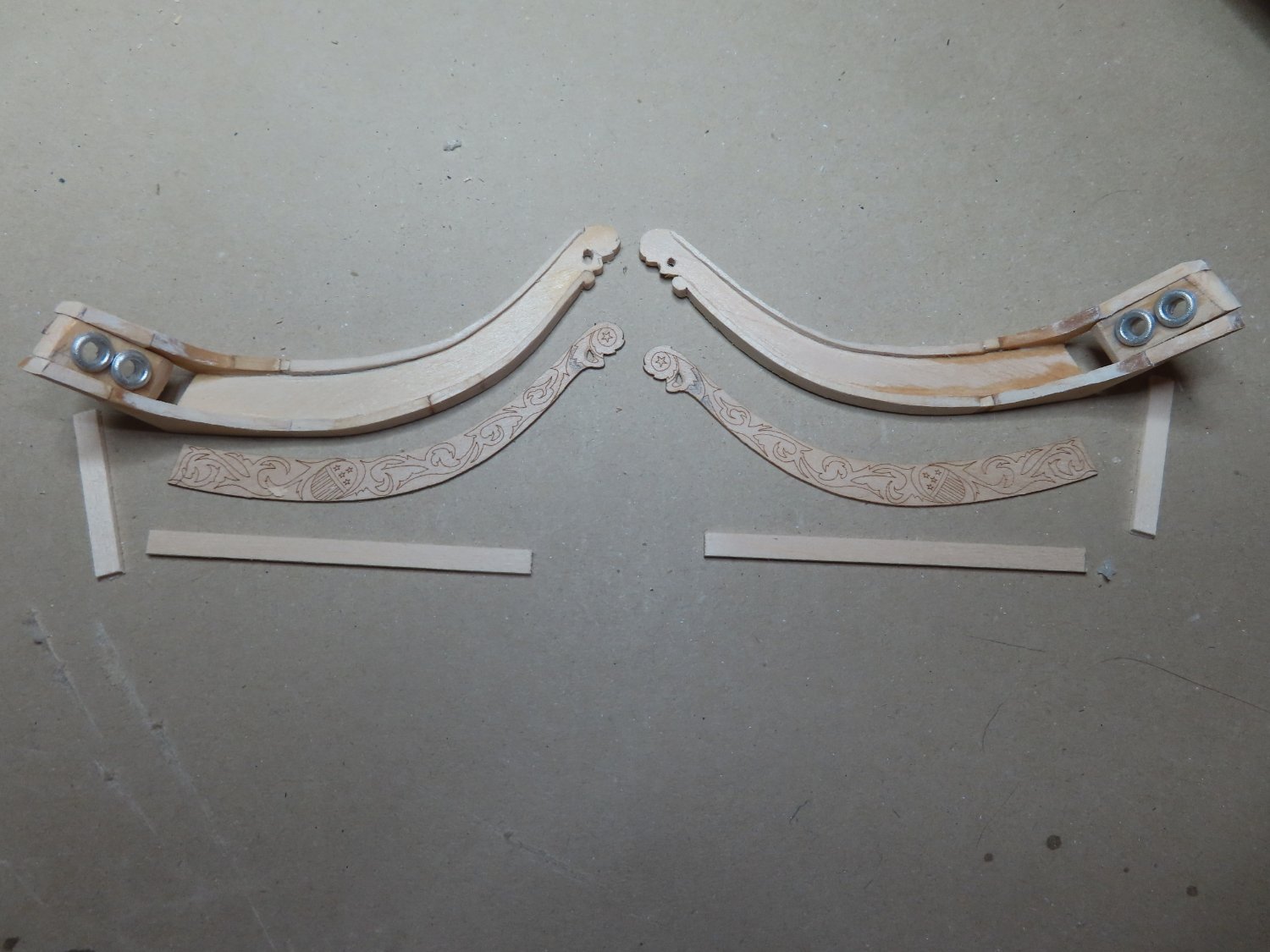
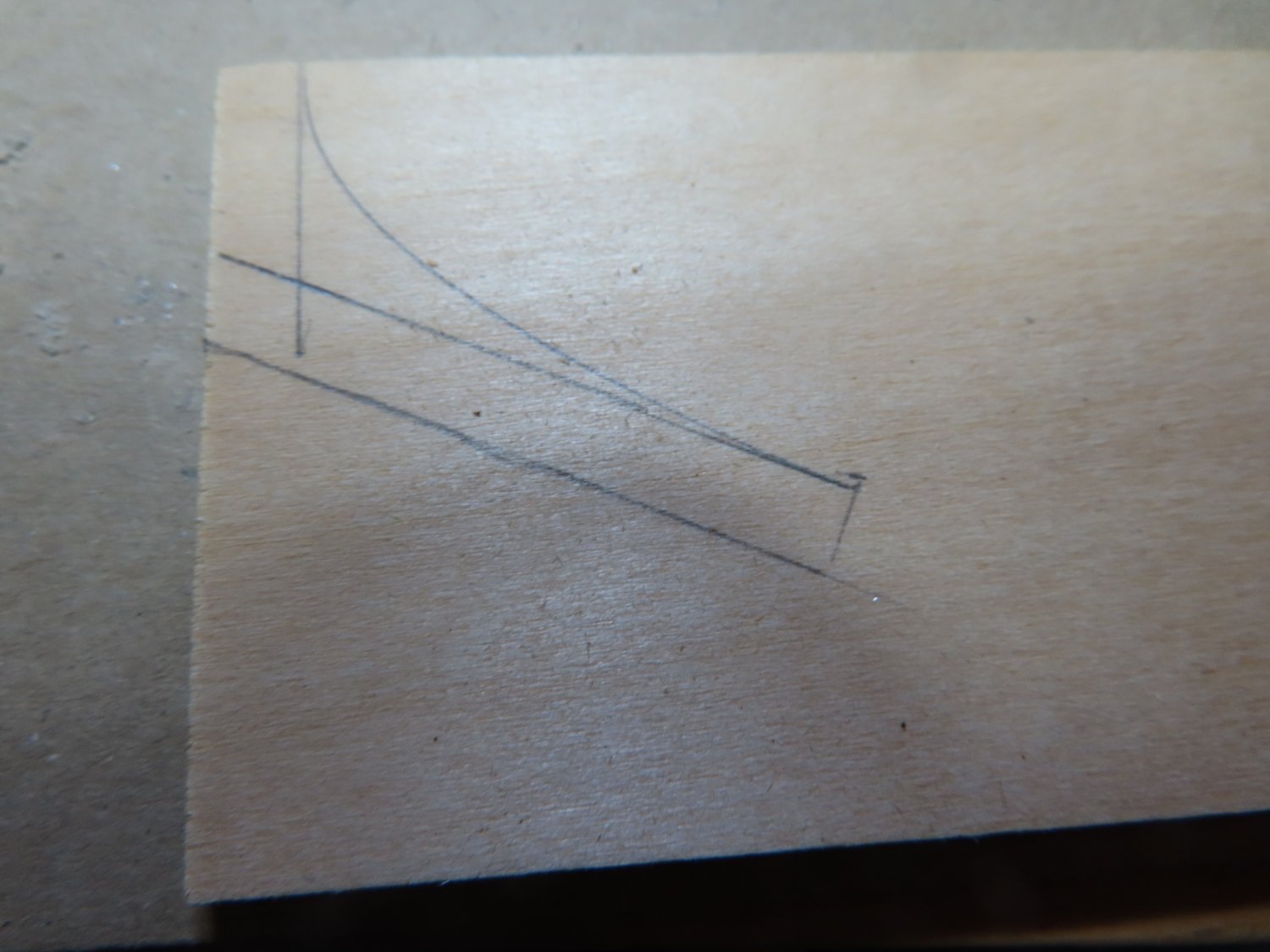
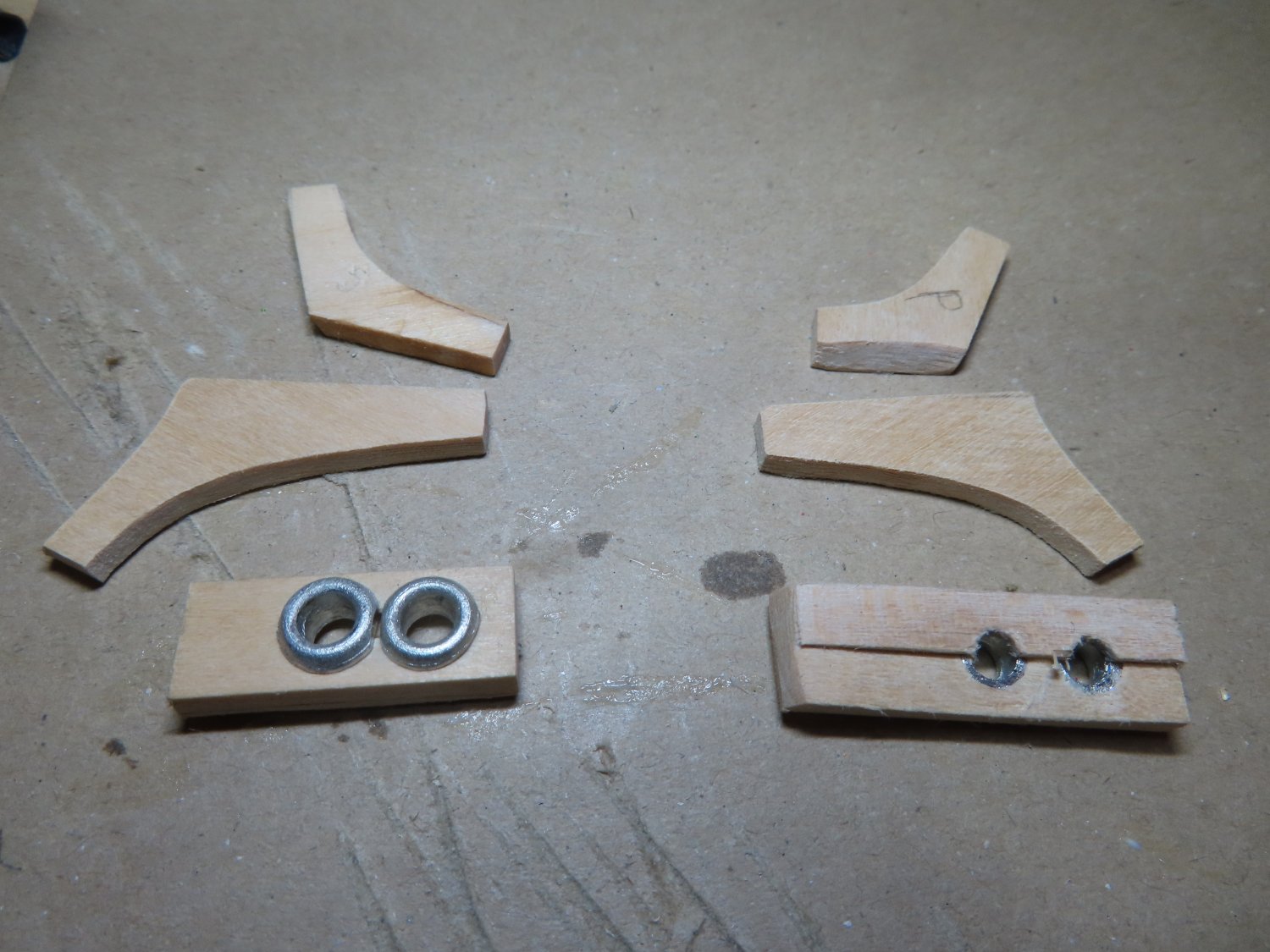
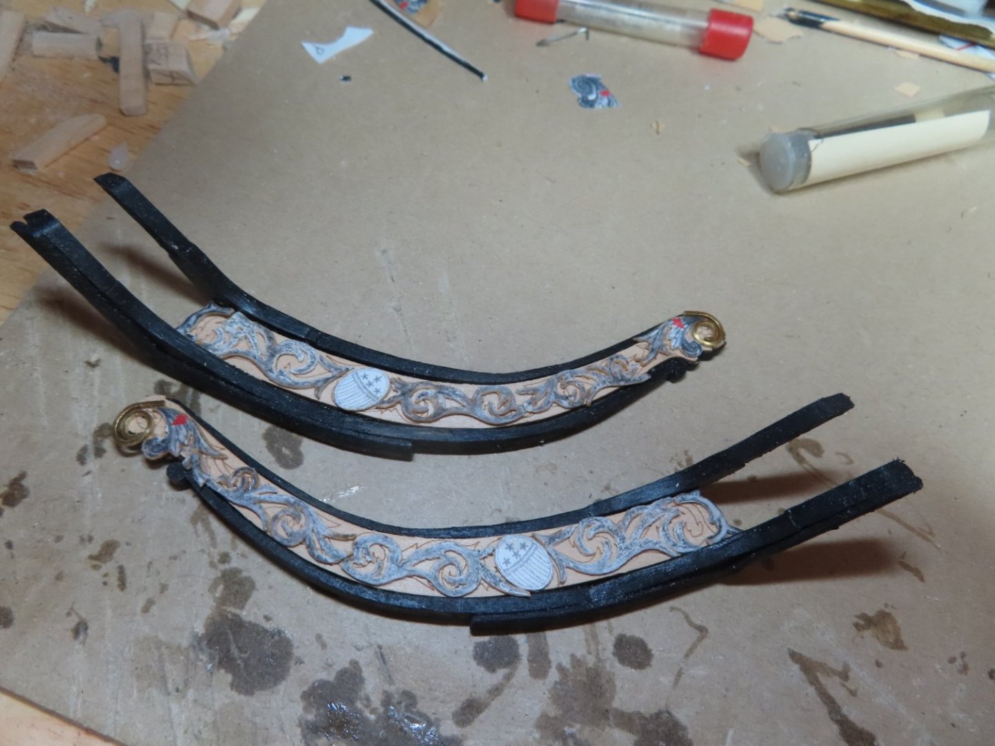
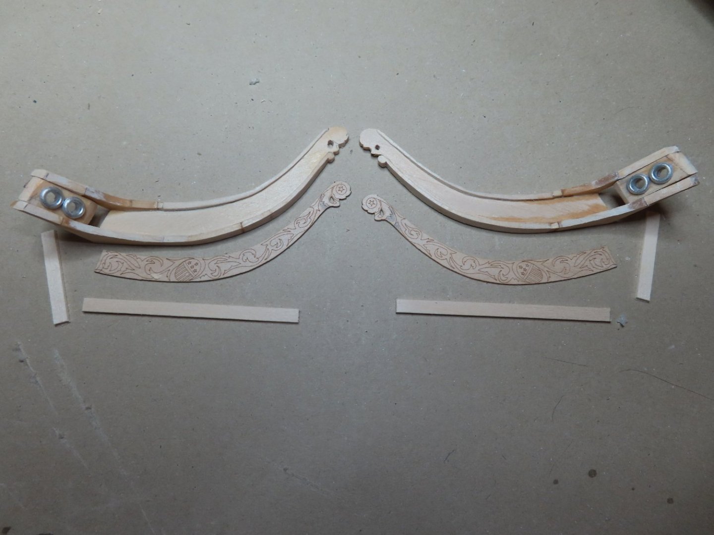
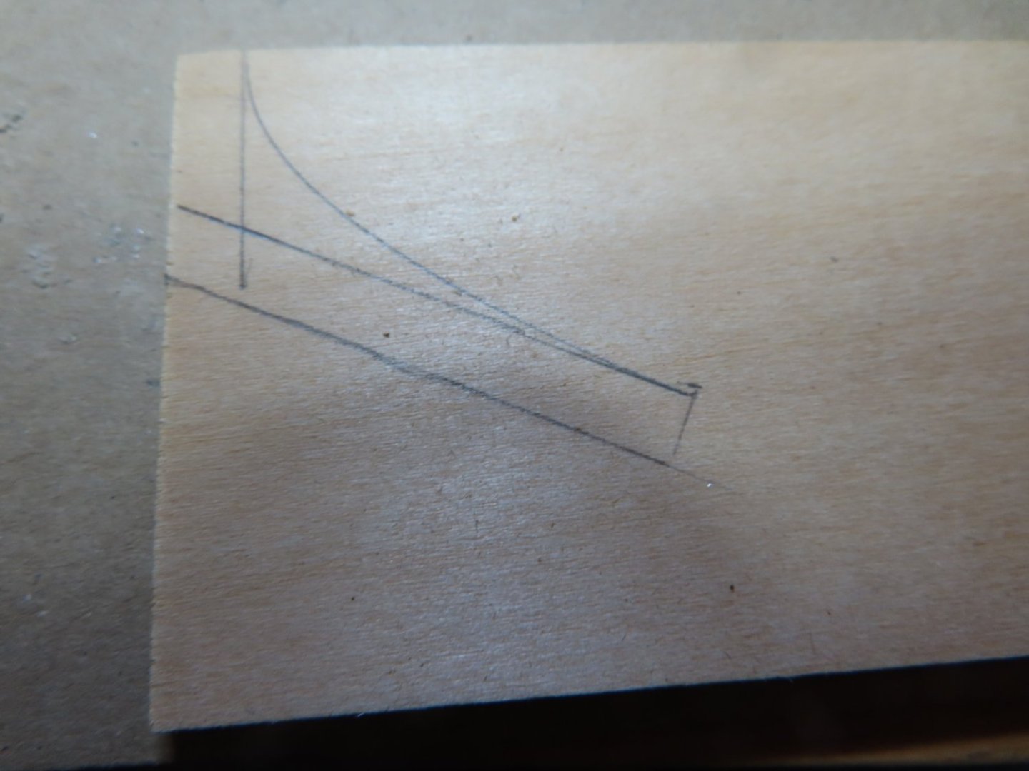
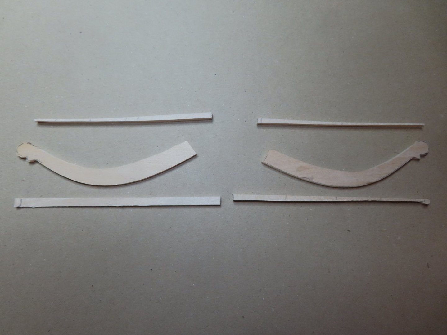
Most builders who documented their builds, created their trail boards from two pieces of wood using the profile in the plans. I couldn’t quite wrap my head what the final shape was supposed to look like or how to insure I had the proper dimensions. The rails bend in all three spatial dimensions. Also, I didn’t trust that my model truly matched the plans, so I used my as-built model and the photographs of the actual ship as my guides. The result was that instead of two pieces, I ended up with three (not counting fudge factor pieces): The rail on the stem, the hull, and the transitional curve between the two, which for me was the key piece. The angle where the trailboard meets the hull was measured using a profile gauge which was original transferred onto a piece of card stock to make a preliminary template which you can see in the first image below. Once I assured myself this would work, the process was repeated on 1/8” thick piece of stock basswood. A parallel line was drawn to it as well a parallel line to the basswood edge which would eventually represent the hull’ A curve was drawn representing the outer edge of the rail as it transitions from the stem to the hull. Satisfied, the process was repeated an additional three times so that a total of four transitions pieces were created: the upper and lower rails for each side of the hull. Based on the photographs, the upper transitional curves were a bit smaller than the bottom ones. Additionally, the hawser opens were constructed using the precast white metal parts from the kit. The back side (shown on the right accounts for the wale being proud of the hull. You’ll notice, my openings as seen from the front butt up against each other per the image from the actual ship and not the plans. In the image, the hawser assemblies have not been trimmed to their final dimensions at this point. Once installed, the hawser holes will be extended into the hull so that the anchor lines will be able to pass through them. The hull trailboard rails have not been constructed yet at this point.

-
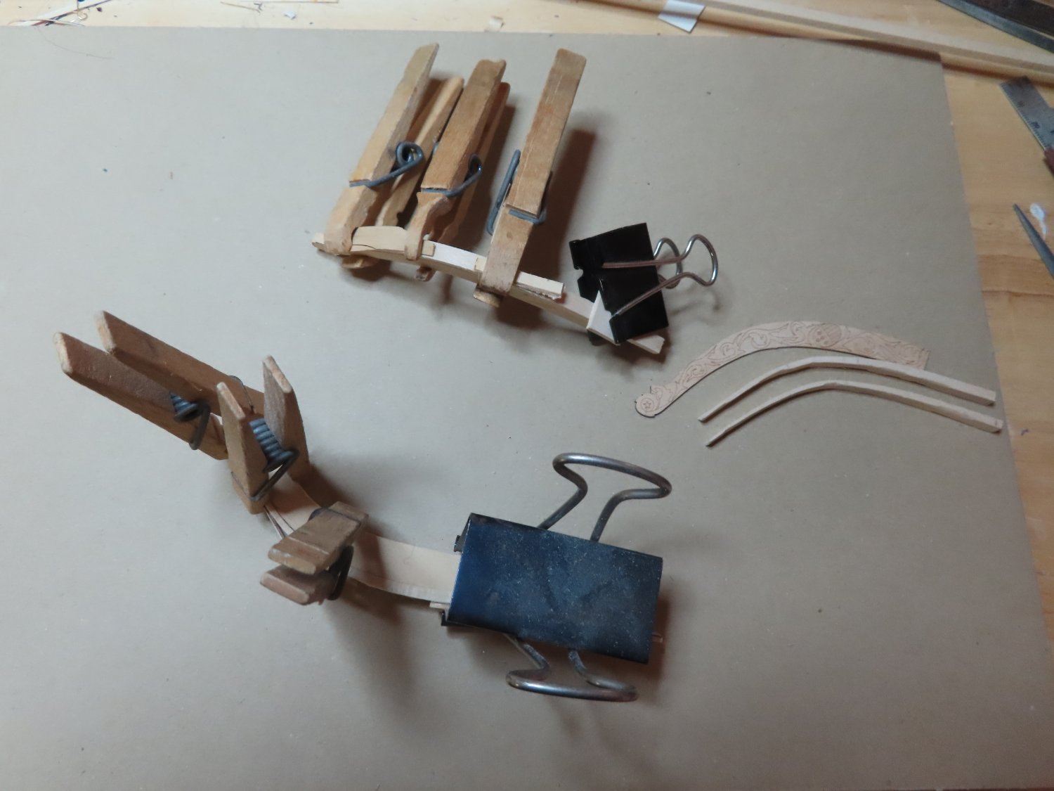
The Head Rails – Trailboard Rails Using one of MS kit’s precut 1/32” thick trailboards as a template, two 1/8” thick trailboard bases were cut and carved from basswood stock. Next, four strips of 1/8” wide x 3/16” thick basswood stock were cut a bit longer than required for the upper and lower trailboard rails. The extra lengths facilitated the carving and bending. The rails tapered from 1/8” to 1/32” at the forward tip of the trailboard. Once the tapering was carved, they were soaked in water for a day and bent using the heating iron method. Then wetted again, they were clamped to the trailboards so that they would conform to their curves and final shapes when they dried.

-
If your model kit is from Model Shipways purchased from Model Expo, they will replace parts that you lost messed up, etc., no questions asked free of charge.
-
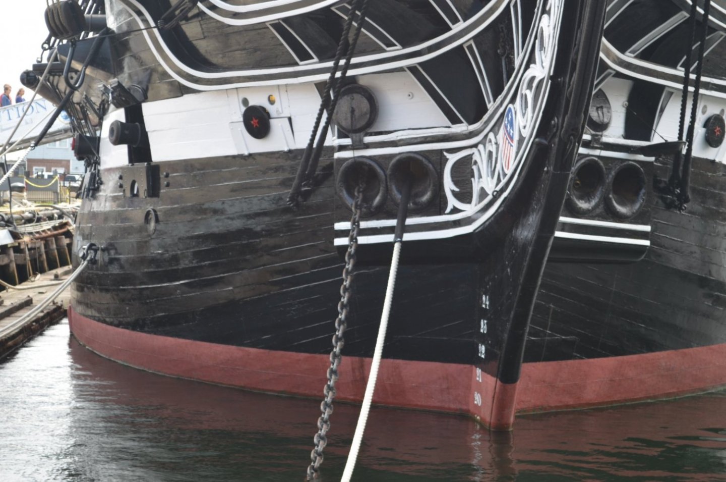
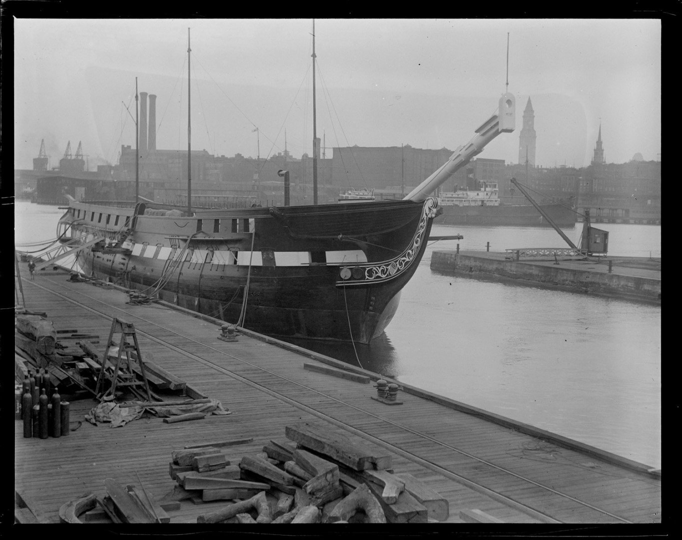
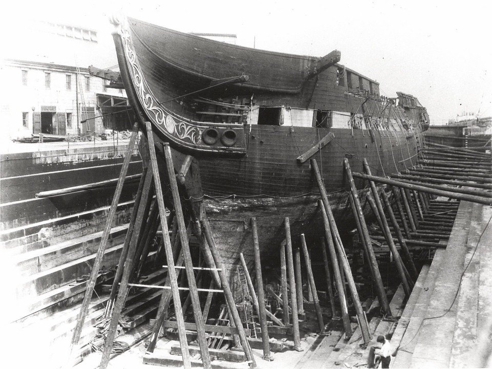
K-mart, I'm just starting my head rails and I am studying everyone build logs to get the best methods. Yours is on my list. Question #1, here as some photos from the 1927 restoration which clearly show the boomkin is horizontal and parallel to the waterline. Question #2, The white piping is raised slightly above the base. Some people use white painted 1/32" x 1/32" wood strips, others like shown in Mr. Hunt's Practicum use vinyl strips. Technically, if you look closely, the piping is painted just on the surface. I hope this is what you've been looking for. Note: You will also see that the cathead and bumpkins are moved aft in the 1927 images from what is shown in the plans, which supposedly are based on the 1927 restoration.

-
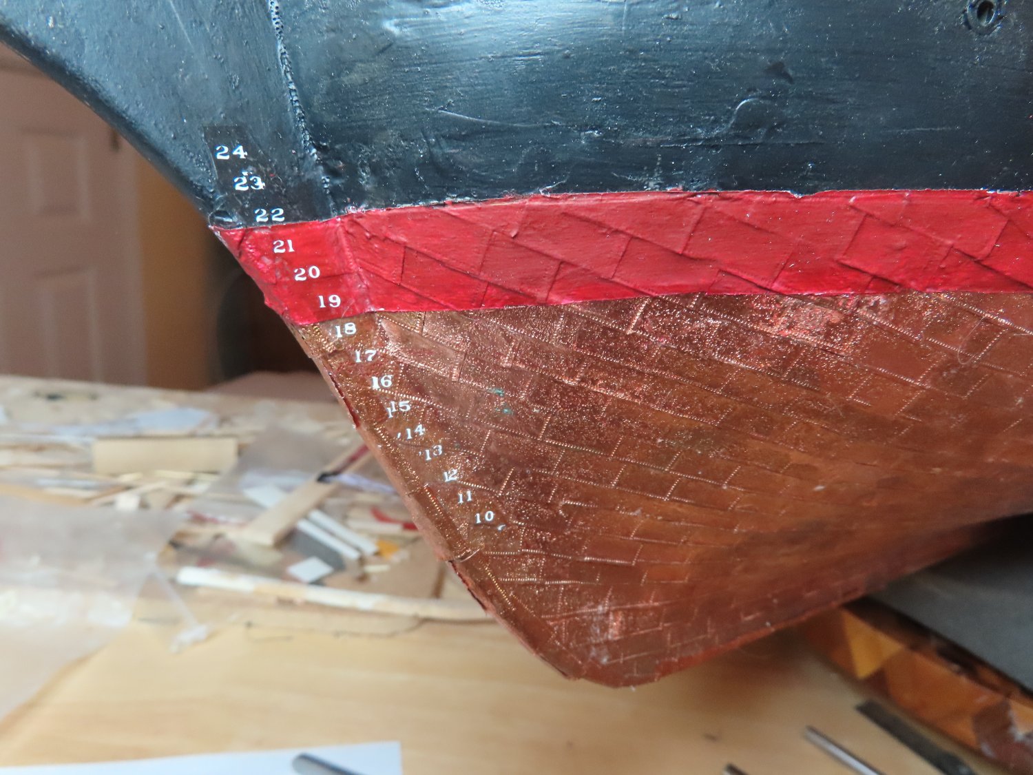
As I feared, applying the transfers to the decal paper was a bitch. I had to use my headband magnifier just to see the digits, the guide marks almost disappeared when trying to find them looking through the transfer sheet, and of course I’m applying white numbers on white decal paper. To add a little more apprehensiveness, I could not afford too many mistakes because I had a limited number of transfers and mistakes were made. Once the port and starboard decals were made, the bonding spray was applied and set aside to dry thoroughly. These were then dipped in water and applied to the hull. The process worked, but my alignments were not as perfect as I would have liked due to the difficulties I mentioned above. Micro-Coat Flat was then applied to remove the sheen and blend the decal into the background. From about a foot away, the numbers are almost too small to be read, so the imperfections are not too noticeable.

-
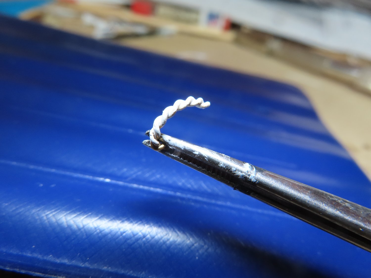
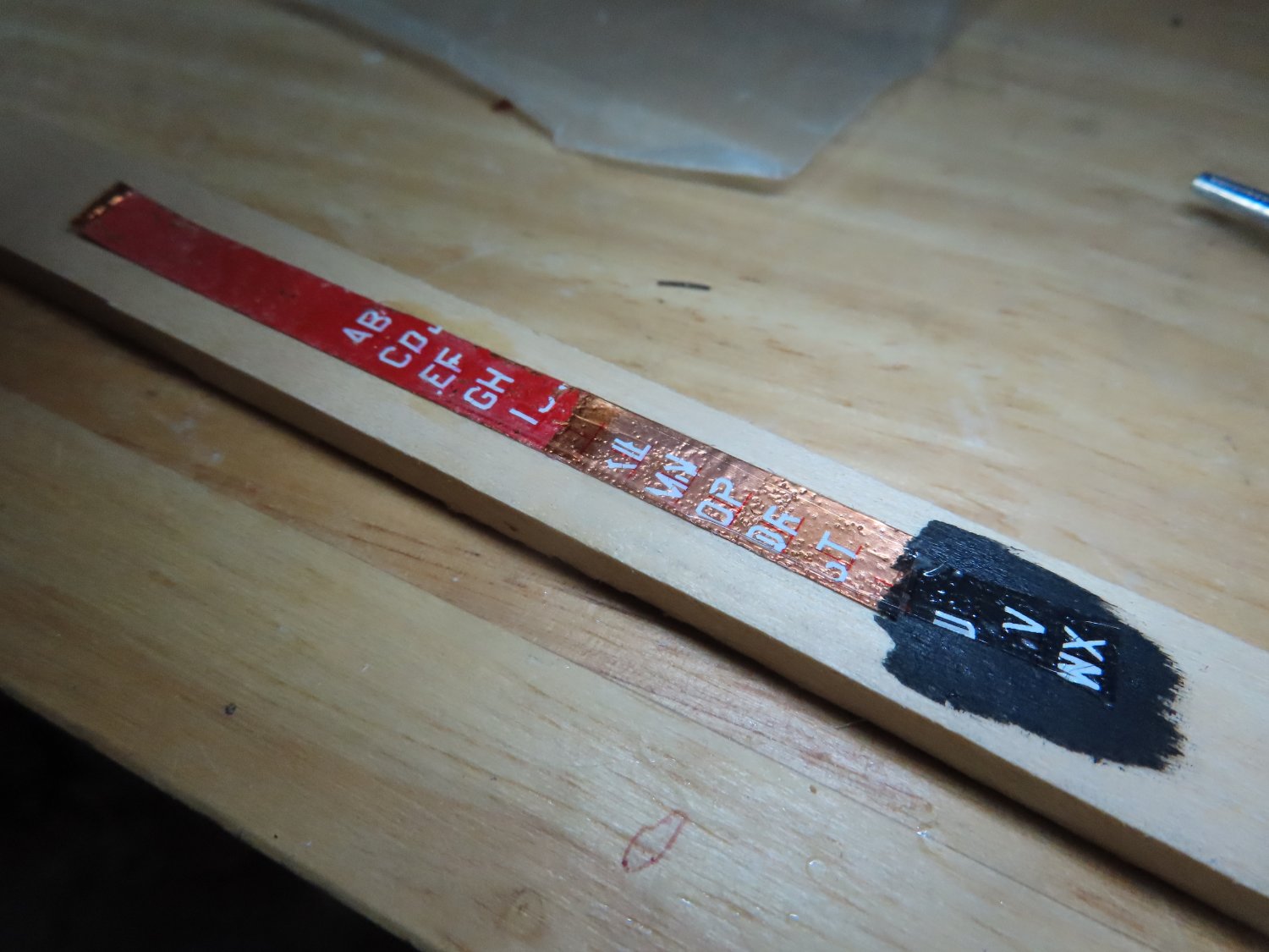
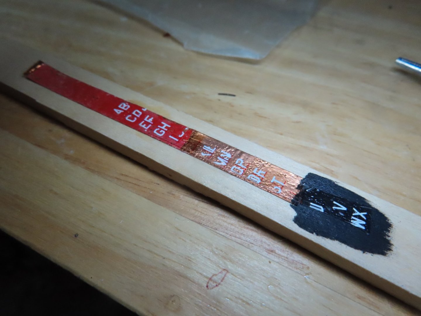
Because I have not seen this process done by anyone before, I did an experiment first. Using lettering left over from the ship’s nameplate, letters instead of numbers, I follow the above plan. I used a strip of copper, partially painted red and black painted wood as my test subject. What I discovered is that it worked, however you had to be very careful and meticulous burnishing the transfers. Because it’s white lettering on white decal paper, it is very difficult to ensure a proper transfer as seen in the image below. I believe there is colored decal paper (light blue I think) which would have made this process a bit easier, but I didn’t have any. The guide marks were essential. Although my marks were fine red and they did seem to disappear once the decal was applied to the surface, I changed them to grey guide mark for safety.
-
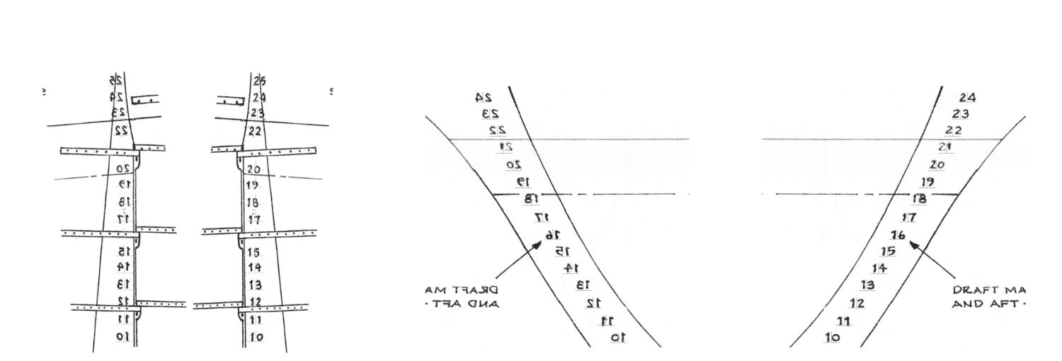
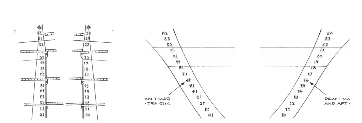
The MS Plan showing the bow and stern draught numbers were scanned to capture them. These were then imported into PowerPoint (my only drawing program) and properly sized the clipped images so they would print at the correct size., These were then copied and flipped vertically so I ended up with port and starboard of the bow and stern numbers. Note: I used the alignment function of PowerPoint to distribute the marks evenly vertically. As it turned out they did not match up exactly with the vertical number spacing on the drawings. Although my spacing will be correct, you can’t see any real difference. Once satisfied, line guide marks (wide upside down “T”) were overlaid onto the numbers to indicate vertical spacing and the curve. You might just make them out in the image below. It’s only the guide marks I need to print. They were to be used to guide me in the application of the dry transfers. Using the guide marks, the dry transfers were to be applied to the decal paper then sprayed the decal bonder. I had no idea what the bonder would do the dry transfers or whether the dry transfers would lift off the decal paper once the decal was dipped into water.
-
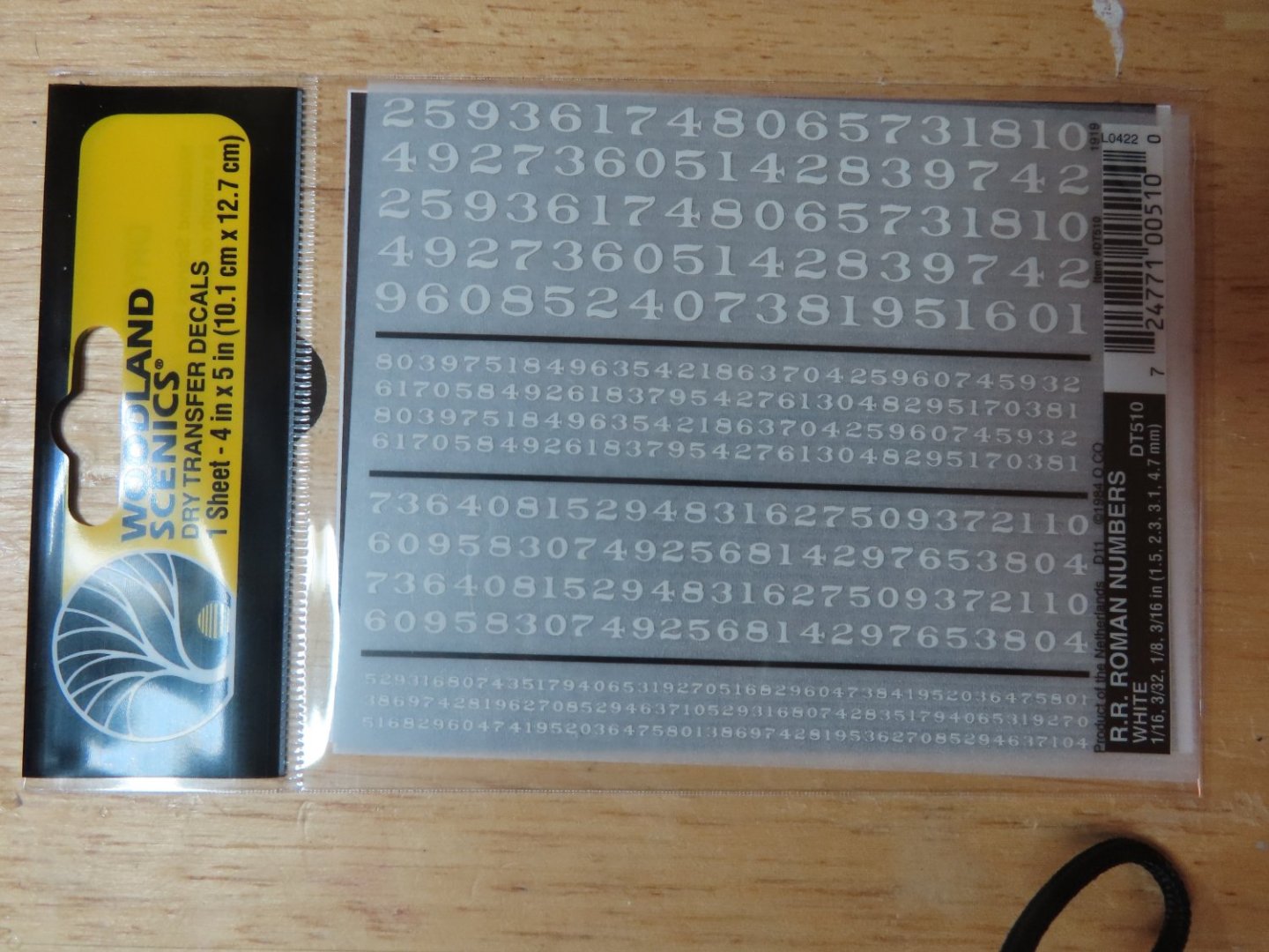
I had a good idea why this was so, and even contacted Robert Hunt to find out why he didn’t add them. He confirmed what I assumed; they are too small to paint on the models at 3/32”. Why not make decals? Also, a simple answer, no home computer can print white because they don’t use white ink. My next thought was to use white vinyl lettering, but I couldn’t find any made at that small size. My last choice was dry transfer lettering. They do make small enough sizes although not in the exact font used in the present-day configuration: Engravers MT. However, it would be very difficult to align them properly directly on the hull with no flat smooth surfaces. But I had an idea, why not combine decals with dry transfers? When I bought the dry transfers for the ship’s nameplate a while back, I also purchased Woodland Scenics R.R. Roman Numbers White # DT510 which came with 1/16”, 3/32”, 1/8”, and 3/16” sized fonts. At this scale the difference in fonts from the actual one would not be noticed. I had to buy three sheets in order to have enough of the proper digits. As you can see from the image below, the font size I was using is on the very bottom of the sheet.
-
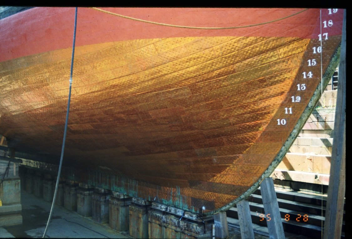
Draught Marks Maybe it’s procrastination or trepidation of the head rails, but I decided to hold off on the head rails one more time because I thought it would be a bit easier to add the draught numbers on the bow at this time, I’ll hold off on the stern until I’ve added the hardware to support the rudder. As I looked over most of the models of the Constitution built by others, the one thing they have in common, they did NOT add the white draught numbers which are really quite prominent for the last 100 years or so.
-
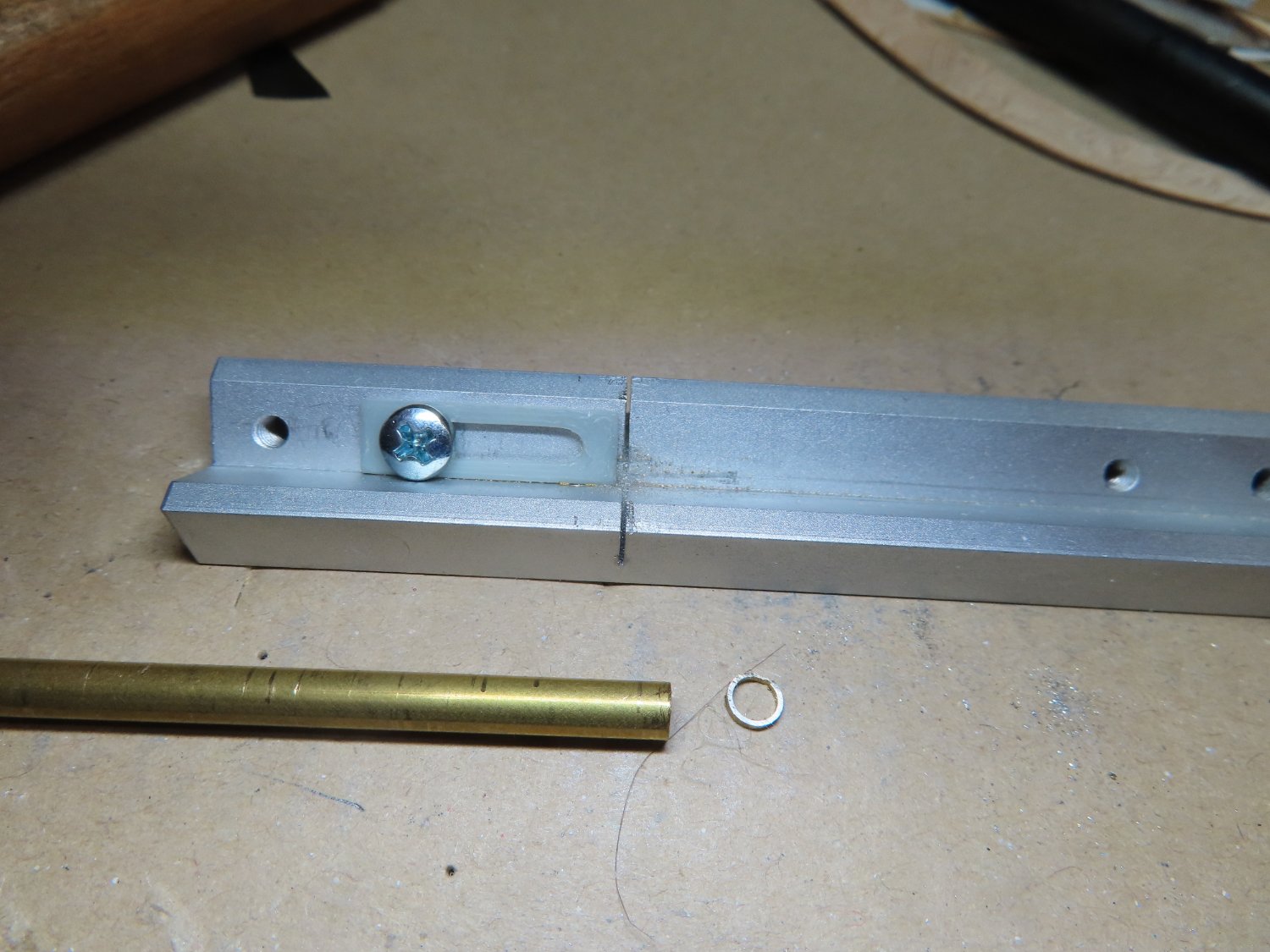
You might consider using brass tubing to make tiny thimbles. Obviously, the hole is already there. All you have to do is slice them off the tubing and paint. If you need to carve a groove on the outside perimeter of the thimble, place the ring on a tapered mandrel which will hold the ring tight while you file the groove. Wood becomes very weak at that scale as you have found out, whereas the metal thimbles remain strong and won't break. At this scale it will be impossible for the viewer to know what material they are are made of. It's a model, not a reproduction, Jon
- 152 replies
-
- 1
-

-
- rattlesnake
- Model Shipways
- (and 1 more)