JSGerson
-
Posts
2,646 -
Joined
-
Last visited
Content Type
Profiles
Forums
Gallery
Events
Everything posted by JSGerson
-
 Your Conny is coming along nicely. You might want to look at how I made my nameplate (see post #611). It's similar to the way you plan to do yours.
 -
I remember this method now! It's a very ingenious and it makes for a fast process. Although your log was short, I was impressed when followed your build. I'm kind of machoistic in doing some things the hard way. My method is time consuming, detailed, and prone to missteps, but I think I'll like the results a bit better. Thank for reminding me. I have some ideas that your method has inspired to streamline my process.
-
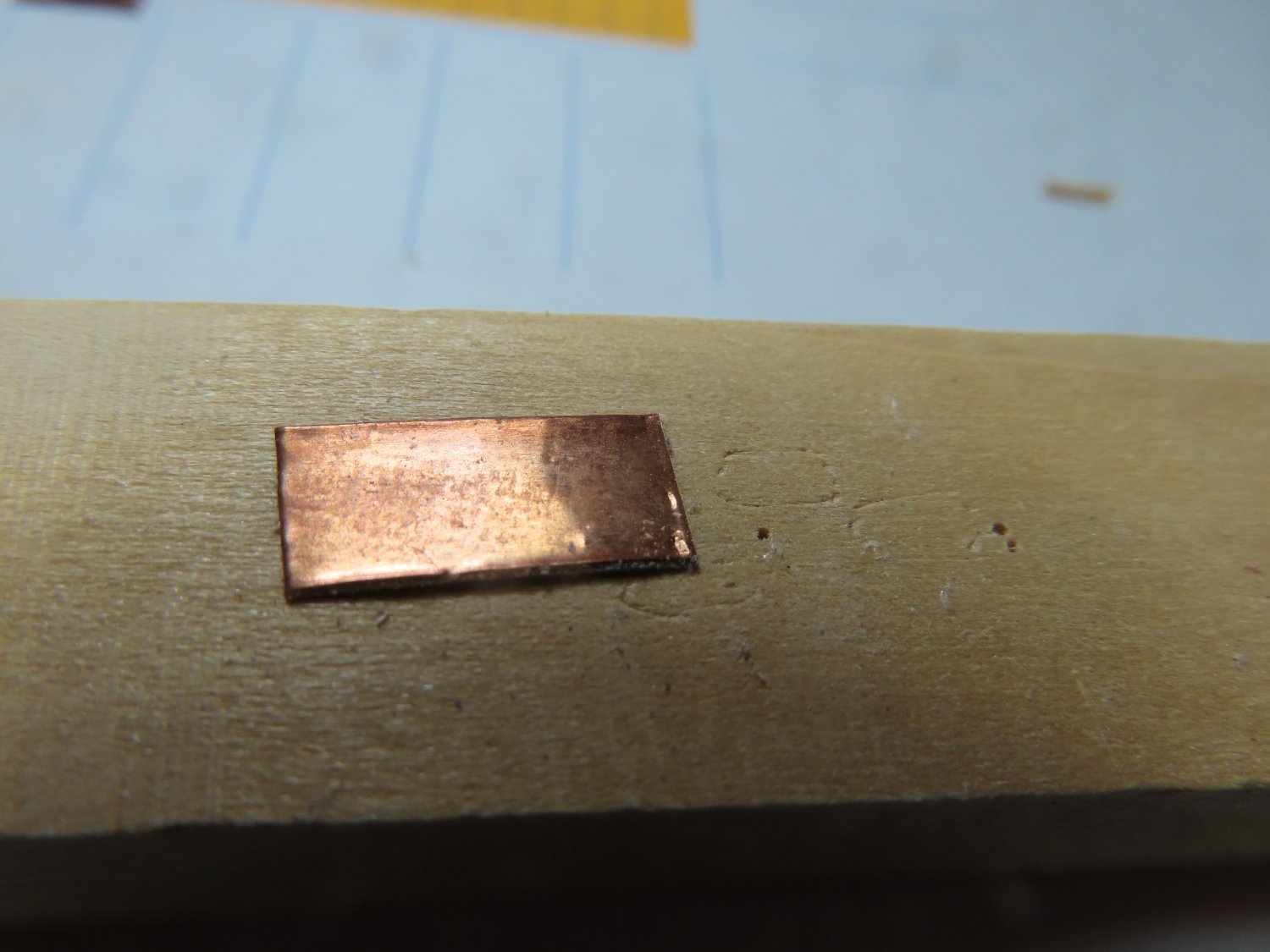
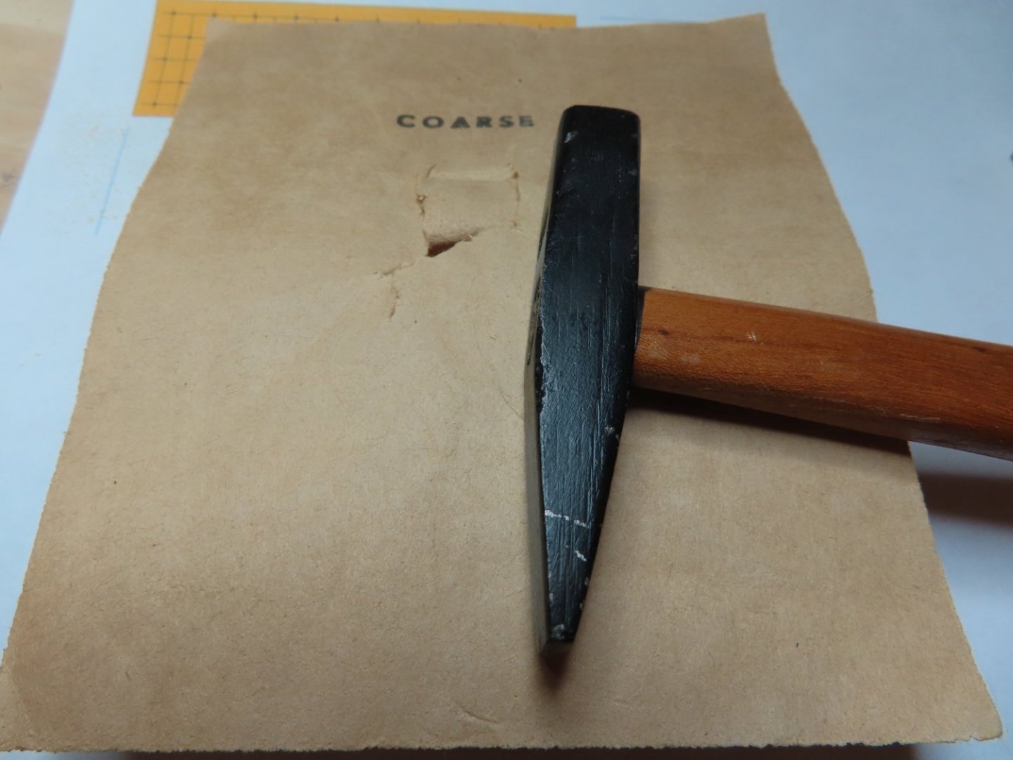
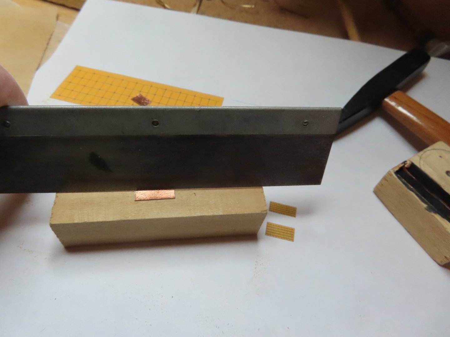
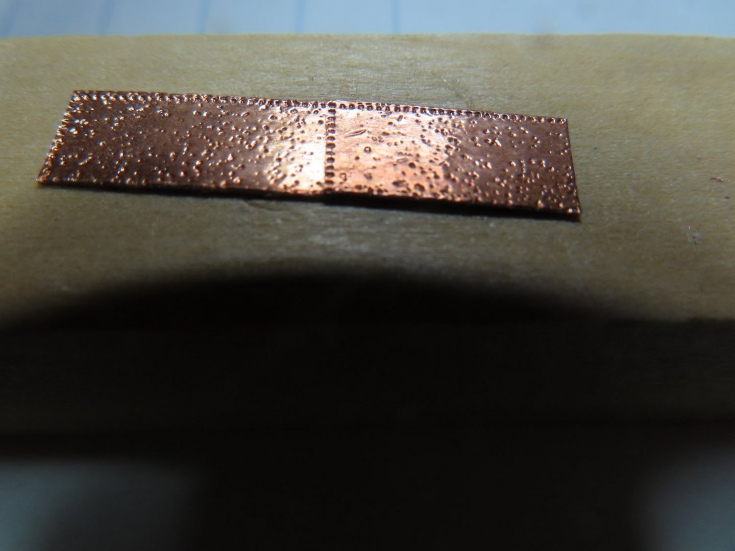
I have several choices for my copper plates: Full accuracy - Make an embossing stamp for ½” x 3/16” plates. Problems, the copper tape is ¼” wide, I need to make the stamp and jig to create 50 interior dimples plus a method to make the close quarter edge dimples Impressionable – give the impression of nail indentations only No nail impressions at all and may or may not overlap the plates I made the pattern for the fully accurate pate by counting the nail heads and their locations on the real plates from photographs. When I reduced the pattern down to scale size, the nail pattern would be indiscernible let alone easy to make. When I considered the number of plates needed, I didn’t think it was worth the effort. What I call the impressionable method is relatively easy to do, but still tedious. The idea is to emboss the copper using sandpaper. The rough surface of the sandpaper would make random impressions in the copper just enough for the viewer to realize the copper has some texture detail, not enough to discern a pattern while cutting down the mirror finish of the copper tape. I do have a method for the edge nails using a method which I’ll discuss below The last method is just to add plain copper plates straight off the copper tape roll without any embellishments, just cut to size. The relies on the idea that the scale is so small, you can’t see the details. I felt that the impressionable method might be the best way to, but I had to make a test run first. I cut a few ½” length strips for my trial and create the plate with these steps: Cover the plate with a piece of coarse sandpaper and using another block of wood (not shown), lightly tapped the block so it forces the sandpaper into the copper. Per Nautical Research Guild’s Ship Modeler’s Shop Notes II, Pgs.138-9 I used a fine-tooth modeler’s saw blade and with a single tap embossed the edge of the plate top and one side. Just rubbing the plate with my fingers to burnish the plate smooth. From just a few inches away, any discernable pattern would have been lost in the full accuracy method, so this method is my choice.

-
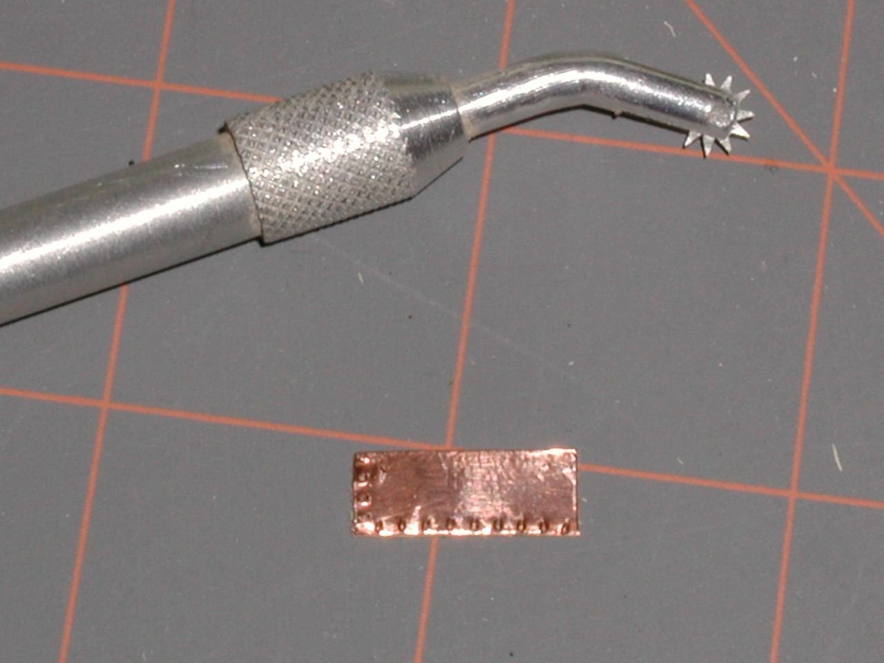
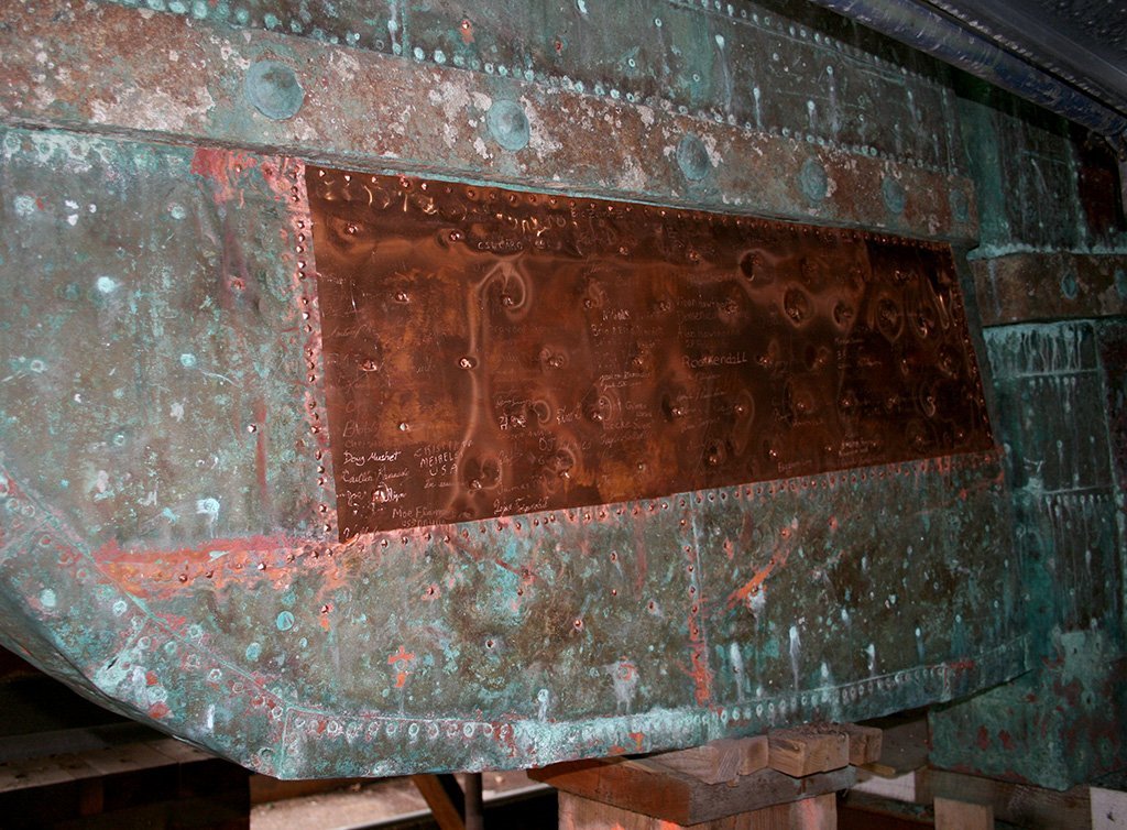
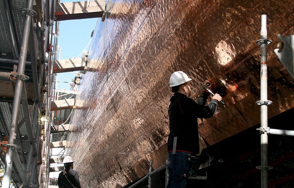
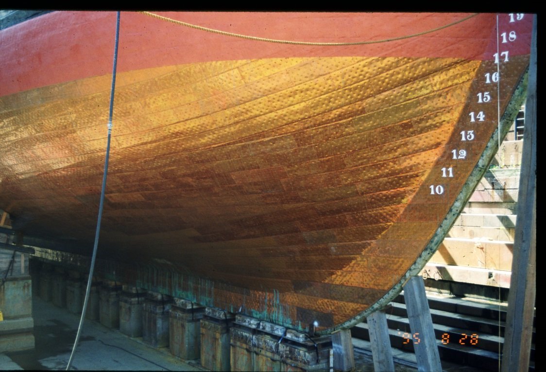
The practicum uses a coppering method which I feel could use a little improvement. Mr. Hunt used a ponce wheel to make plate edge dimples on the copper plate edge. Unfortunately, I feel they are oversized for the scale and look more like a boilerplate. A lot of builders used this method of just outlining the plate, and some made them with bumps raising above the plate like rivets. But after seeing actual pictures of the Constitution’s plating, I going to attempt an alternative method of embossed plates. According to Roger Frye’s Shop Notes in the Nautical Research Journal V66-4 Winter 2021: Per the quote above, the range between 1:96 scale and the Model Shipways kit at 1:76.8 scale, is left to the judgement and skills of the builder. The plate nails make small minor depressions so the indentations will have to be almost flat, just enough to disrupt the natural smooth mirror finish of the copper tape that is provided in the kit. The first image below is what Mr. Hunt created. The following images are of the actual ship for comparison.
-
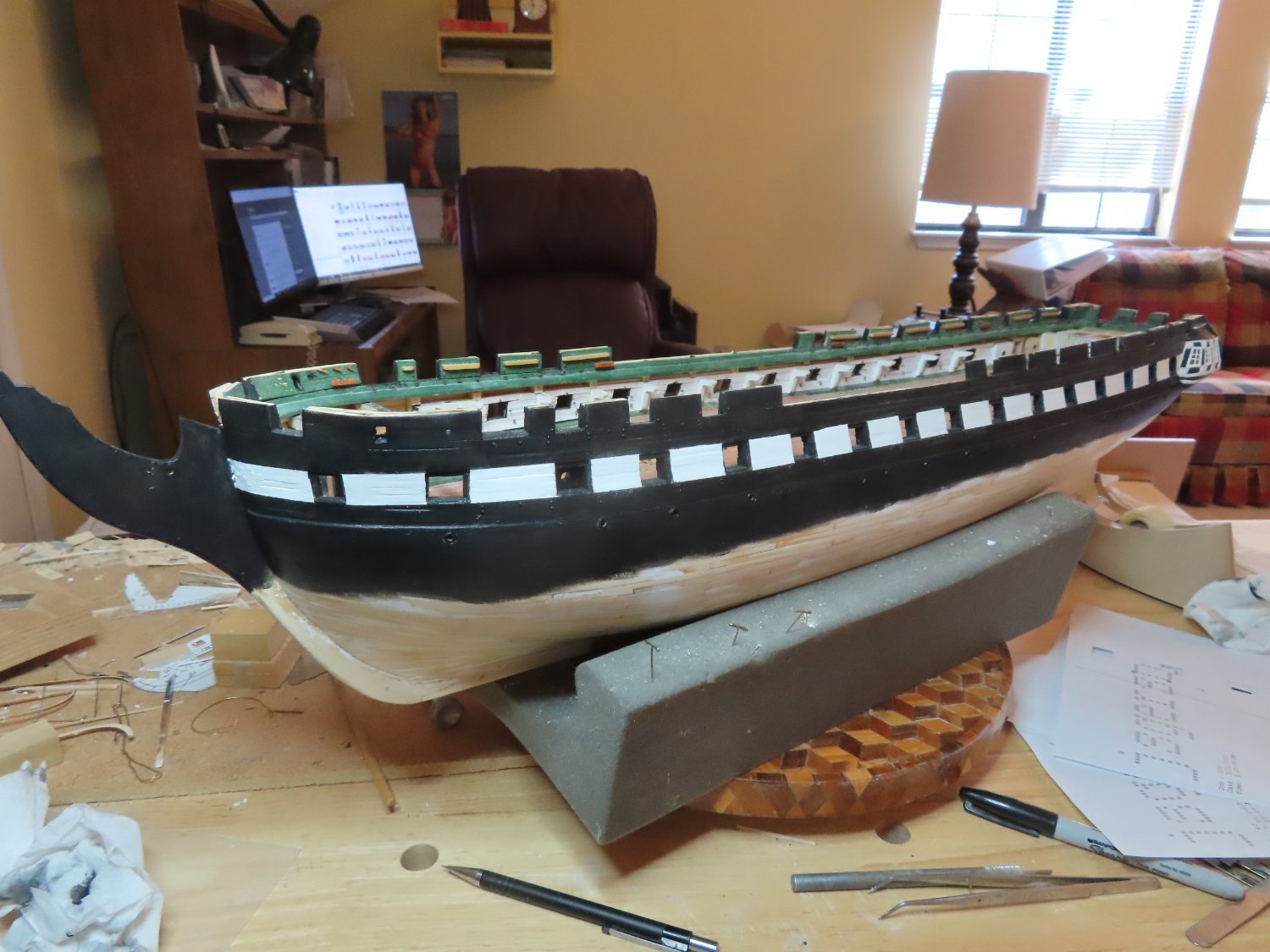
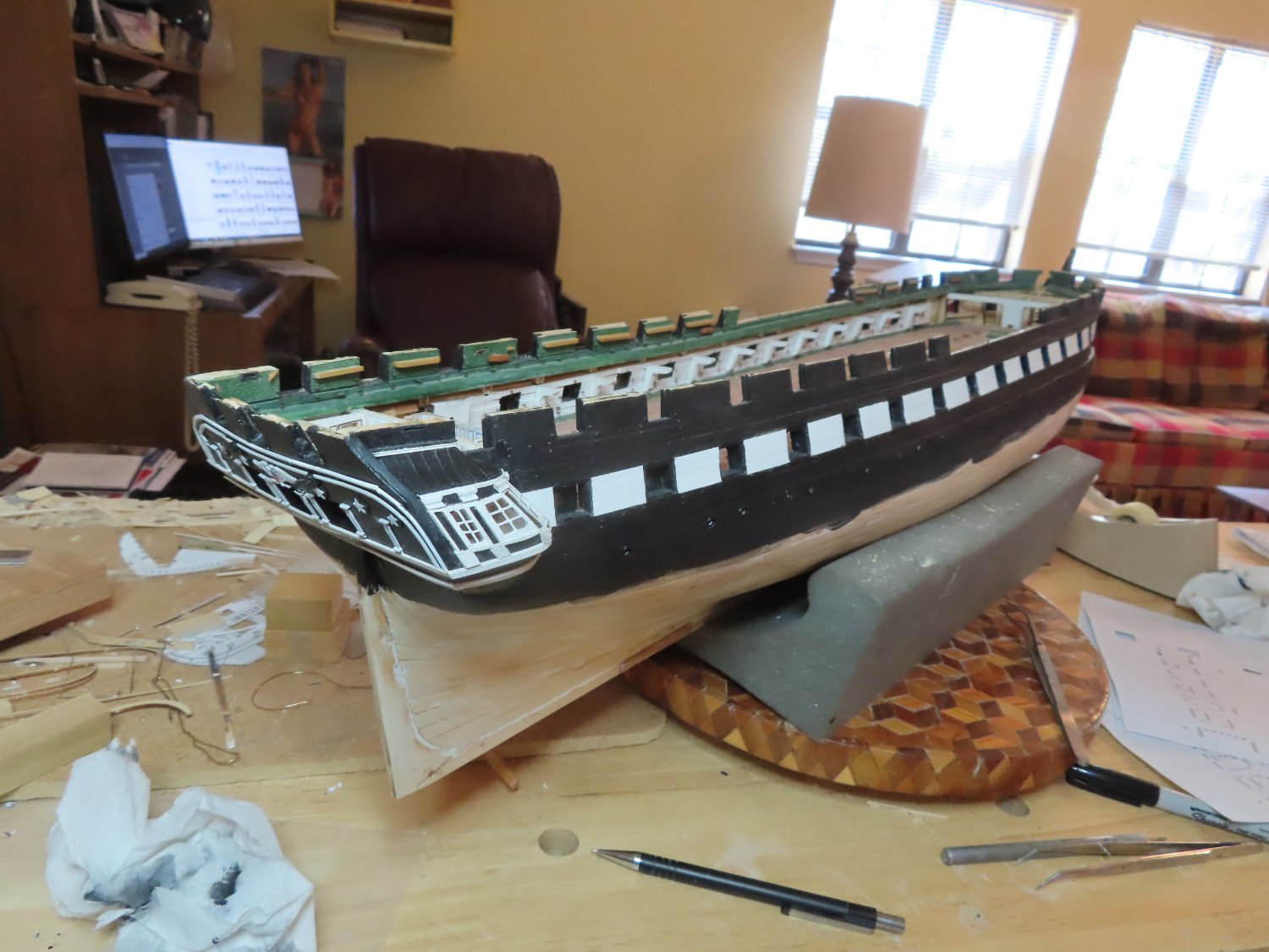
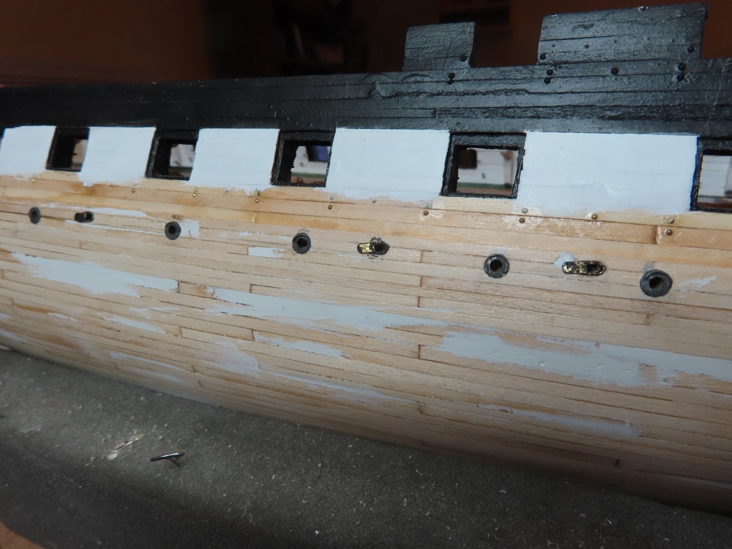
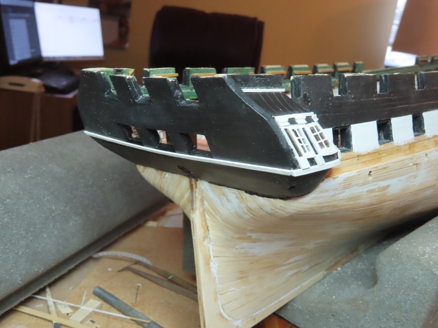
Coppering Preparation Once more I’m deviating from the build sequence laid out in the practicum. Instead of moving on to the stem with all its complications intricacies, I’ve elected to work on coppering the hull before any delicate structures are added to the stem. Thus, I painted more of the hull black to just below the waterline. The copper plates will eventually define the actual waterline once they are installed.


-
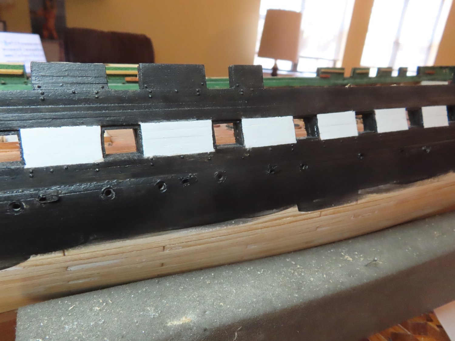
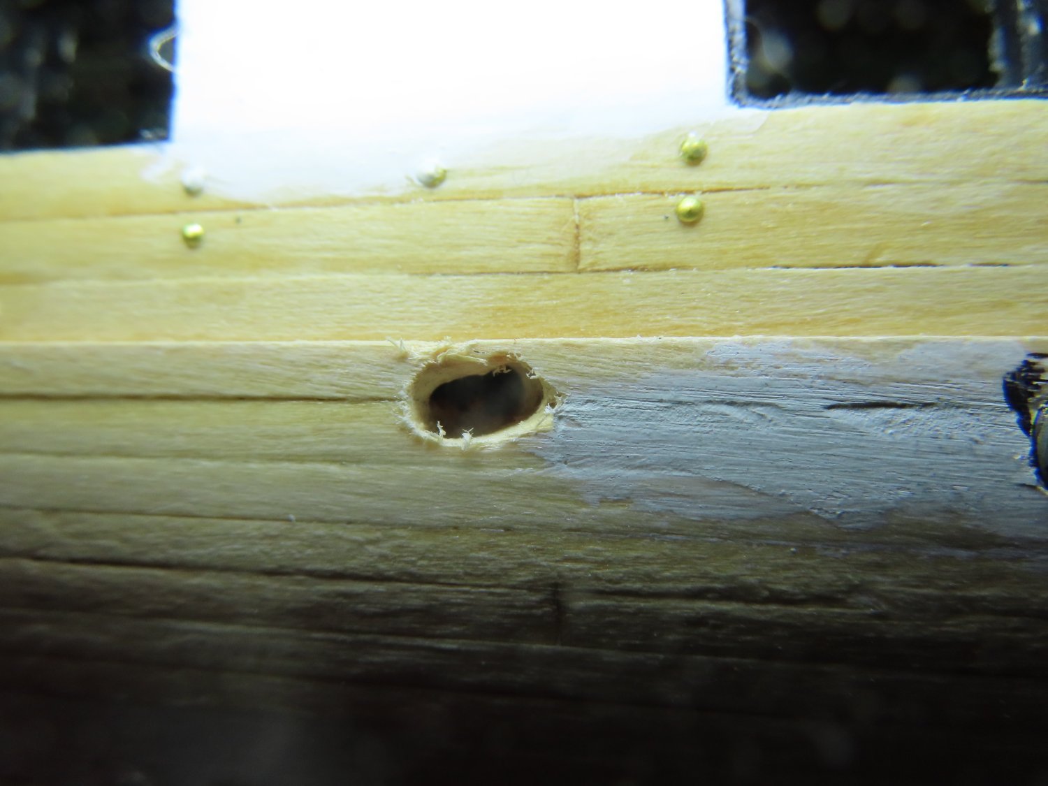
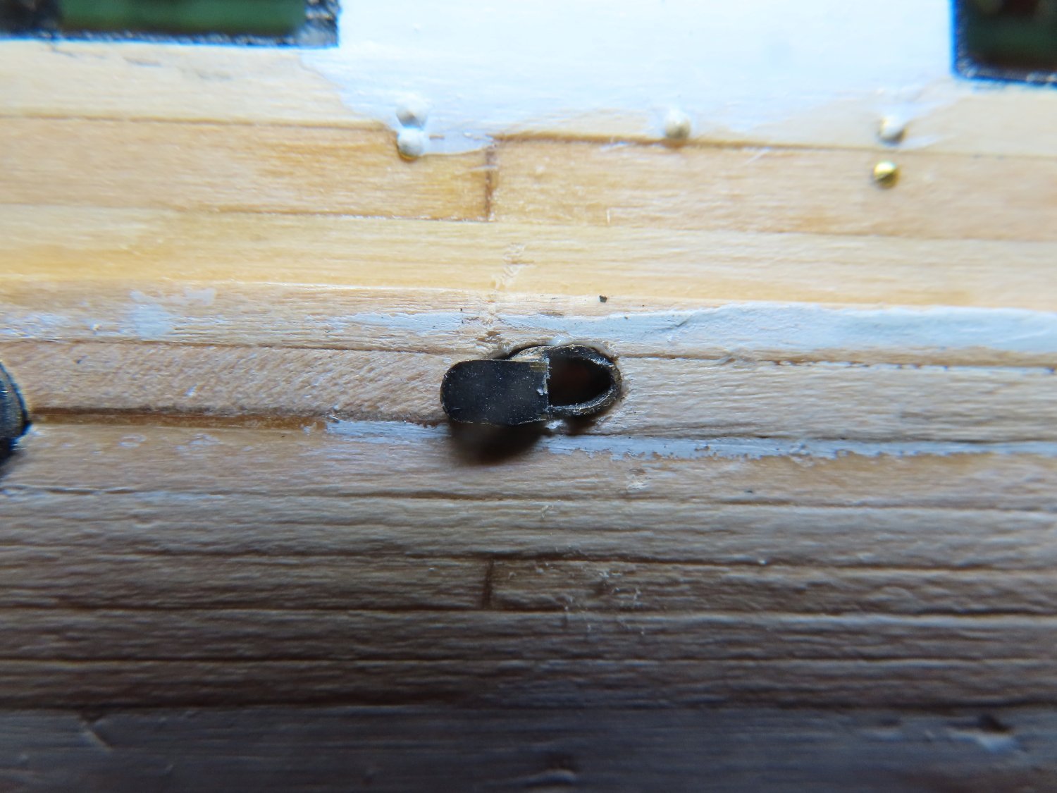
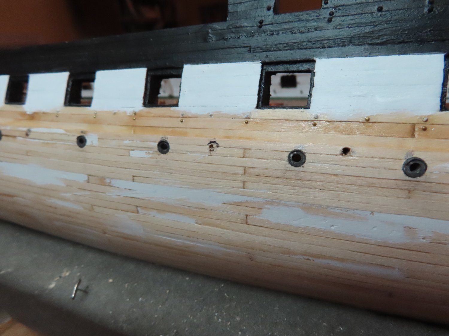
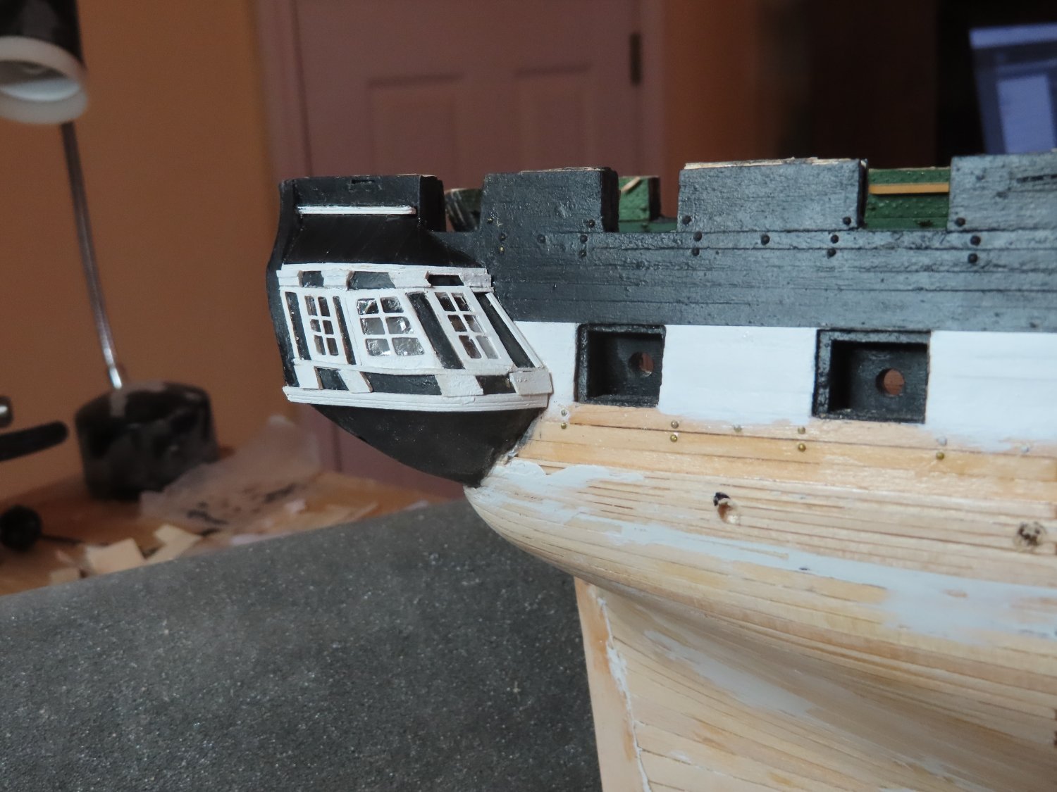
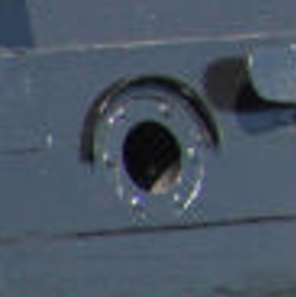
The openings in the hull required a bit more manipulation with drills and files because the final opening shape was oblong. Also, during the installation, I had to make sure that the scupper lid swung open forward on both sides of the ship due the requirement that the lid hinge (which is covered by the open lid) is always on the forward side of the scupper. I’ve not found another builder who has done this.


-
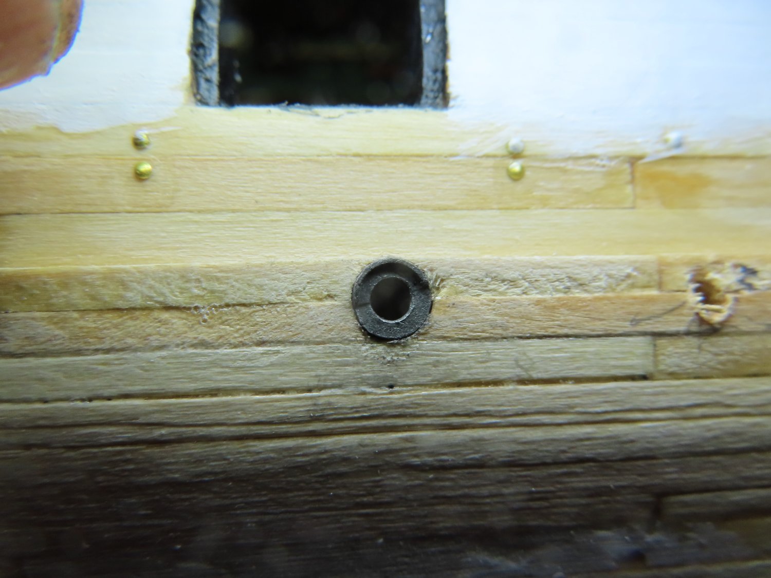
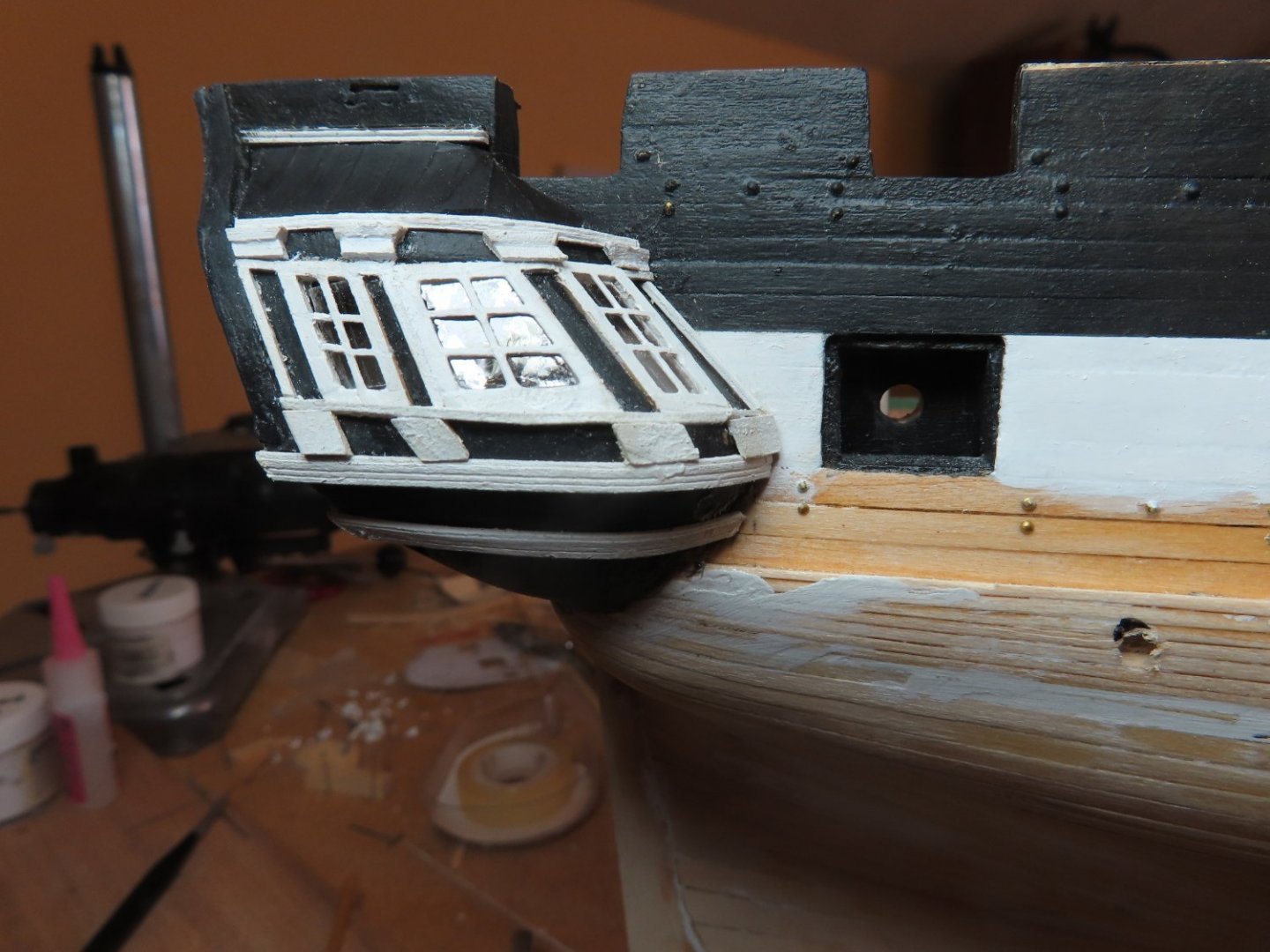
When I last handled the hull scuppers, I had just fabricated them, drilled the hull pilot holes, and painted them black (not shown below). You may note, some of the paint wore off due to handling. This why I blackened the port lights. They will be repainted after they are installed on the model.

-
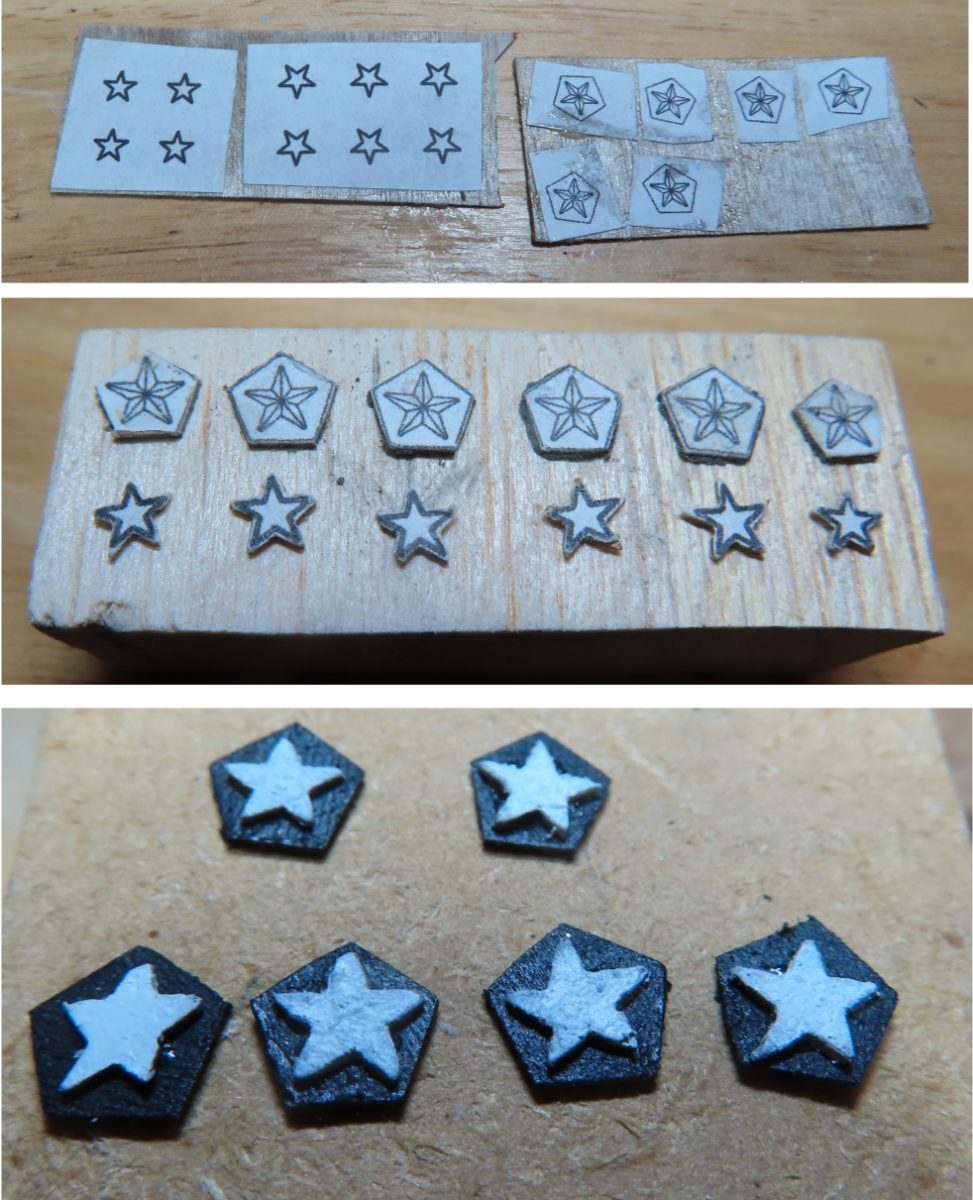
k-mart: In theory, the stars were simple to do. In actuality, trying to hold the tiny 1/64" thick plywood stars to cut/carve/file/sand them to shape was a bit demanding. As you can see from my photos, some came out better than others. I suppose if I had used Styrene sheets as my material for the stars, I might have been able to get more precise and cleaner cuts. I just didn't have any. From a distance of one foot, you can't see the imperfections. Hope you have good results. My eyes lids are doing fine so far. The pacemaker is just coming to it end of battery life. I got 13 years out of an expected 10 year battery so this will be just a routine replacement. Thanks for your concern.
-
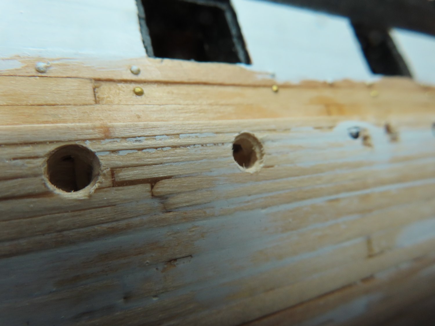
After trimming the metal port lights castings, they were blackened so as to show what little detail they had. However, they might be painted later because they didn’t show much. The original positioning holes that were drilled into the hull last time were finalized with a shoulder to accept the metal parts properly. The castings were installed with PVA glue so that I could adjust them if need be.


-
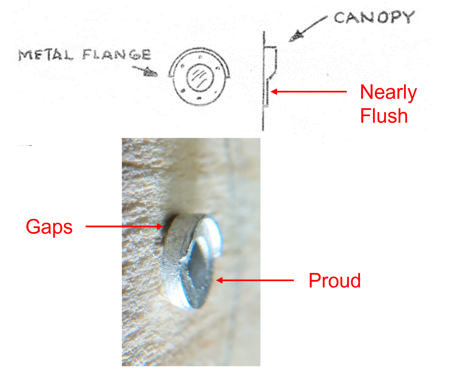
Update Just an update on the health of my eyes, I just had my 3rd eyelid surgery in March this past week. The surgeries were to correct eye lashes curling into the eyes instead of out, which irritated the eyeballs, affecting my vision. That’s 6 surgeries (2 on the left eye and 4 on the right) since December 2021. This doesn’t count the two cataract surgeries in 2020. I had complications in all but the last two surgeries. So far, I still can see, and the eyelids appear to be healing well. Hopefully I won’t need any more work on the eyes. However, pacemaker replacement surgery is expected before the end of the year. The “Golden Years” tend to get a tad rusty. Berth Deck Port Lights Continued Back in July 2021, which if you dig back in this log (starting at posting 543 and 545), I was going install the berth deck port lights and scuttles into hull. I had marked and drilled pilot holes for their positions into the hull and discussed in detail how and why I was going to do, what I was going to do. However, I didn’t go any further than that because I decided to work on the quarter galleries and transom first. Well, your long wait is over. I had noticed on some of the other Model Shipway builds that the modelers were installing the port lights incorrectly. They were installed proud of the hull. According to the kit plans, and as evidenced on the actual ship, the only part of the port light that is proud of the hull is the canopy. I planned not to make that mistake.

-
Thanks for the conformation Robdurant.
-
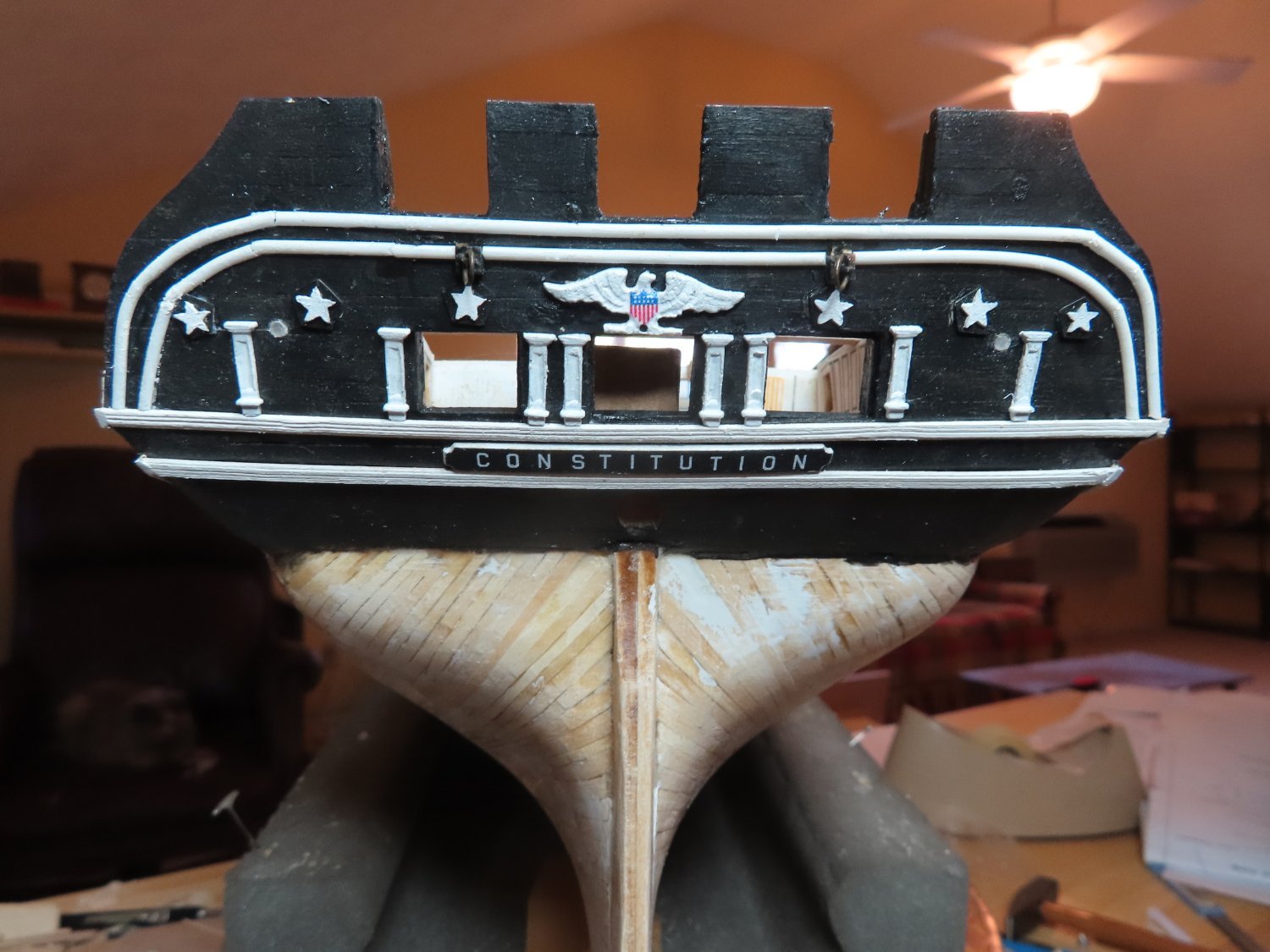
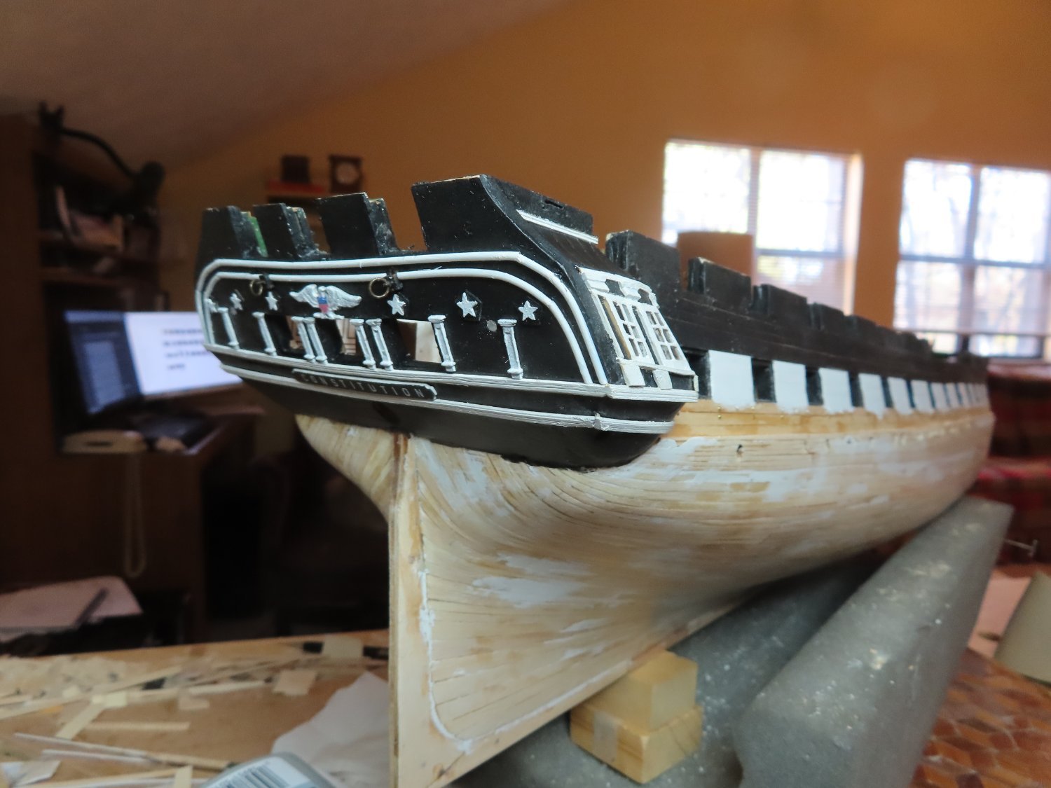
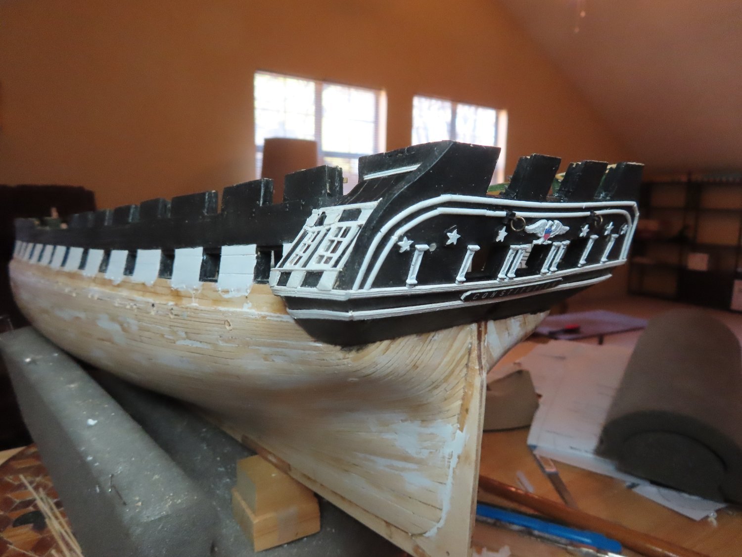
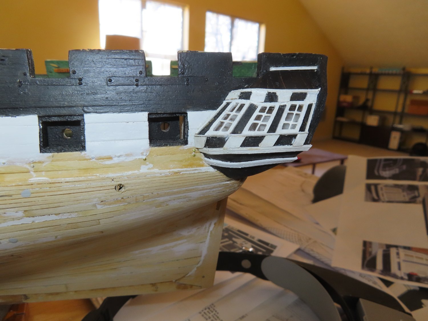
Here is how the transom looks now.


-
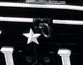
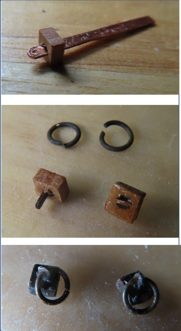
Transom Ring Bolts There are two large ring bolts located on either side of the eagle. A horizontal tab with a hole in it holds the vertical ring. The bases were made of 1/8” x 1/8” x 1/16” pieces of wood. The horizontal tab was fabricated from 0.016” copper plate. I wanted to use brass plate, but I didn’t have a brass plate thick enough. Holes were drilled into the tabs to accept the ring and the end was filed to a half round. Both the copper tabs and the rings were blackened. The wood blocks were painted black, and holes were drilled to accept the horizontal copper tabs. The tabs were inserted into the block holes and glued with PVC glue so that the glue also acted a hole filler. Finally, the excess copper was cut off and the back of the block sanded flush. The rings were then inserted into the tab holes. The white transom trim was cut to accept the ring bolts and they were glued into place. The gun port lids are the last thing to be installed on the transom. These I will hold off on until I install all the lids to ensure consistency in fabrication.
-
Transom Stars If you look carefully at images or the actual ship transom, you will notice that there are 6 white stars which are mounted on pentagon bases which in turn are mounted to the transom. The practicum provides a template for the stars. Four are one size while the two outside end ones are slightly smaller. The kit shows them on the plans but does not provide any laser cut or precast stars. Neither the kit nor the practicum addresses the pentagon backing. The US Navy plans do provide the details for the complete star. Using this information, the stars and pentagons were printed to scale, cut and rubber cemented to 1/64” plywood. The plywood was cut to shape. It should be noted that the stars are faceted and not flat in real life, but at 1/76.8 scale that detail is lost and not worth the effort to recreate. If fact, I had difficulty just creating the star’s basic shape due its small scale. The stars were painted white and pentagons black, then assembled as one unit.

-
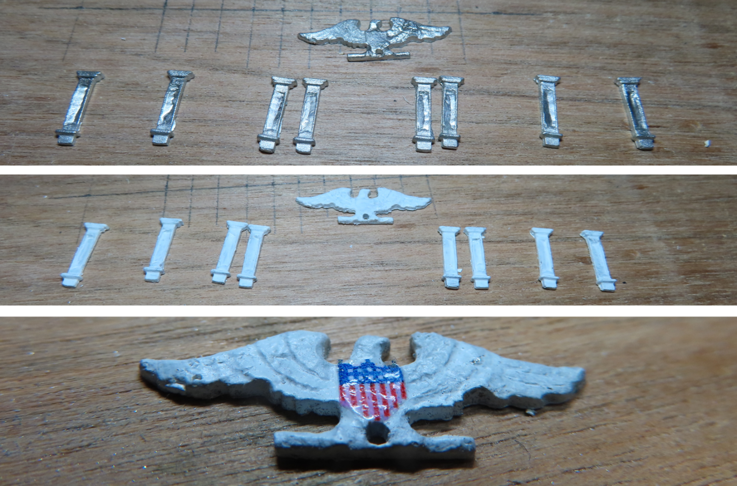
Transom Gun Port Columns and Eagle The practicum gives the builder two choices: use the kit provided columns or scratch build them. Mr. Hunt scratch built his from styrene. In the end he states: “the kit parts, when painted white are quite adequate and due to the size of the parts, I feel it will be very difficult for most to make these pillars.” In this case, I chose the easier route, and used the kit parts For the eagle, I used the kit provided pre-cast decoration. I have no carving talent. The practicum provides a scaled image of the eagle chest flag shield, which it instructs to be printed on paper and cut out to be glued on. I chose to make a decal. The decal was applied to the eagle and coated with a small amount of softening agent, Micro Sol. This allowed the decal to conform better to the minor irregularities of the painted precast metal. Note the decal is shiny in this image because it was still wet when I took the picture.

-
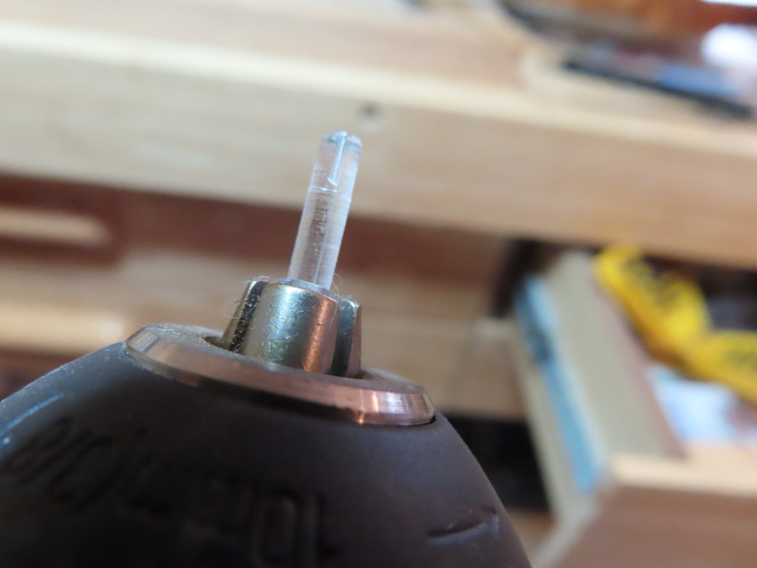
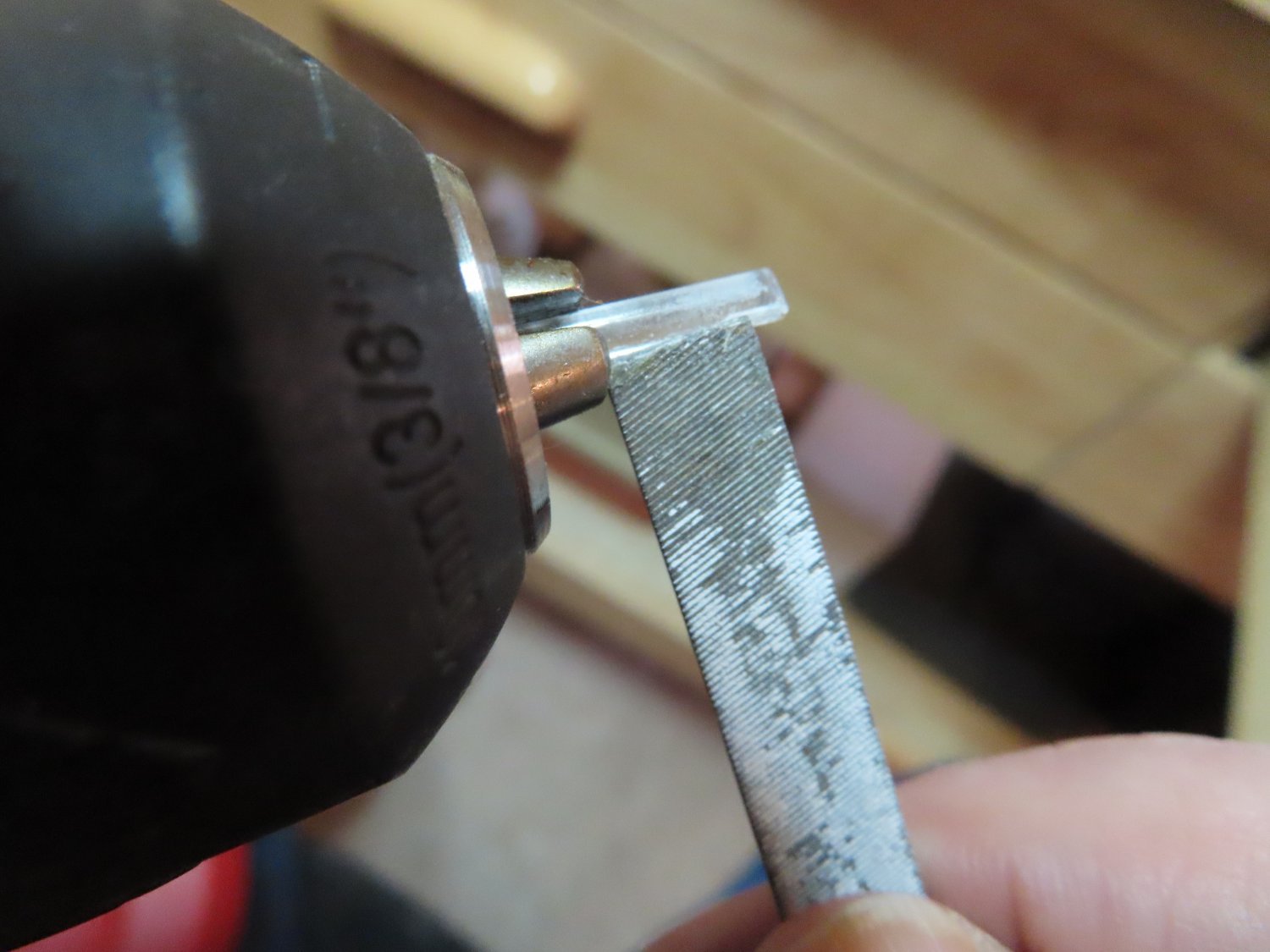
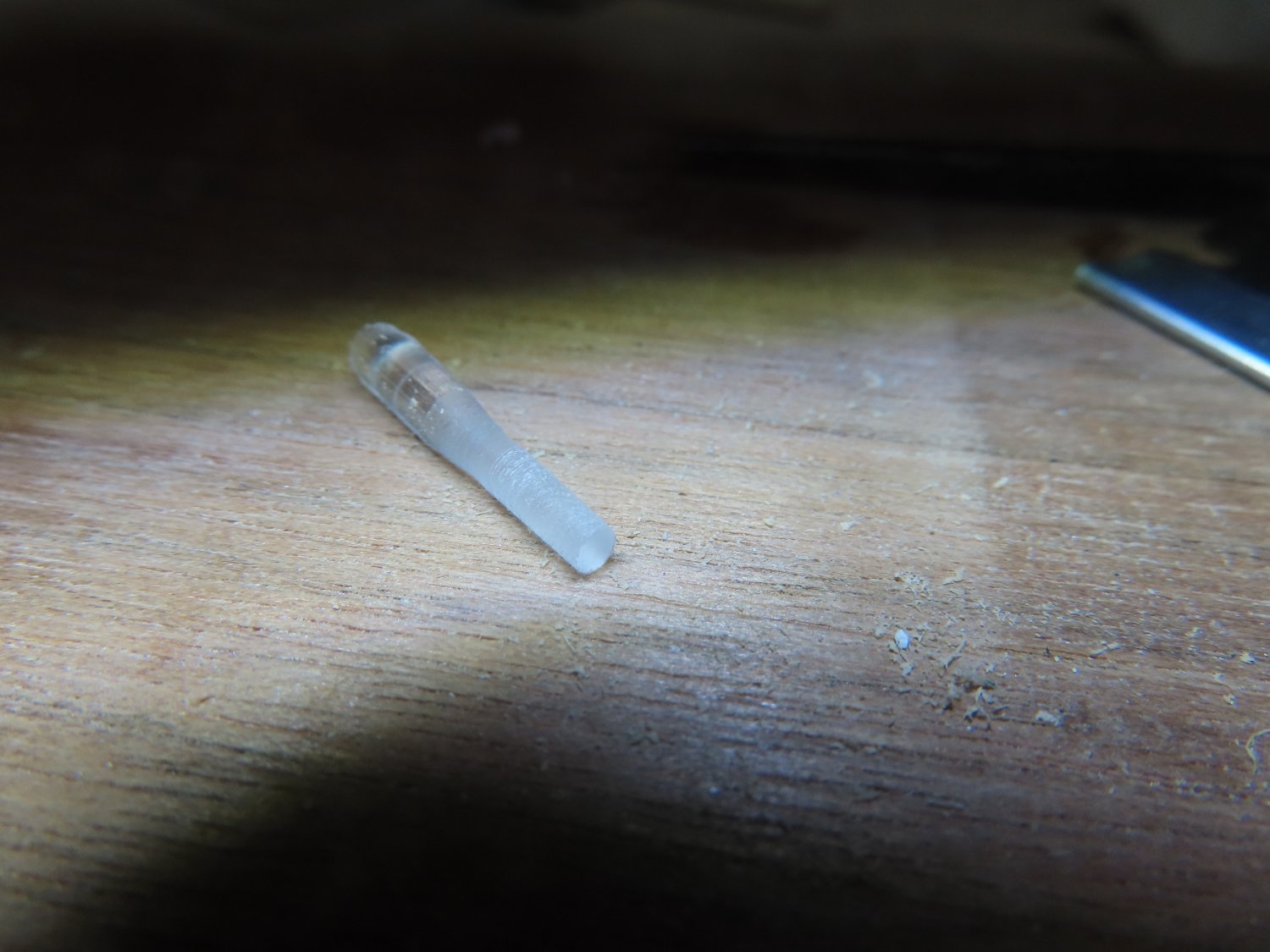
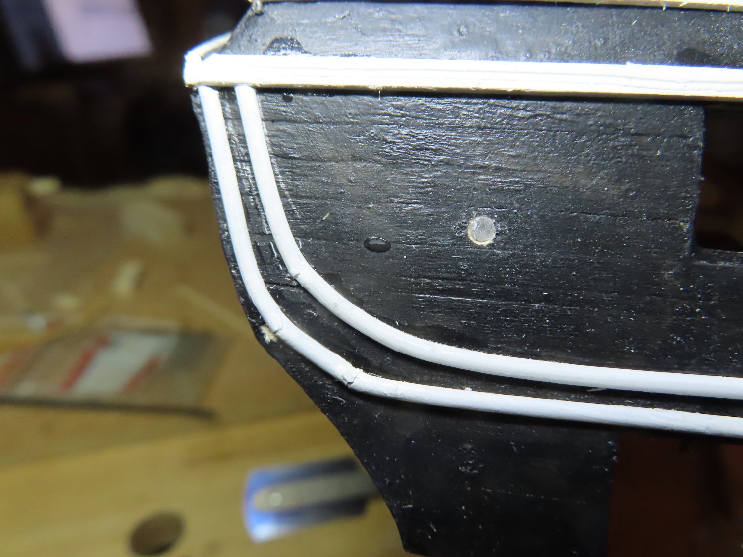
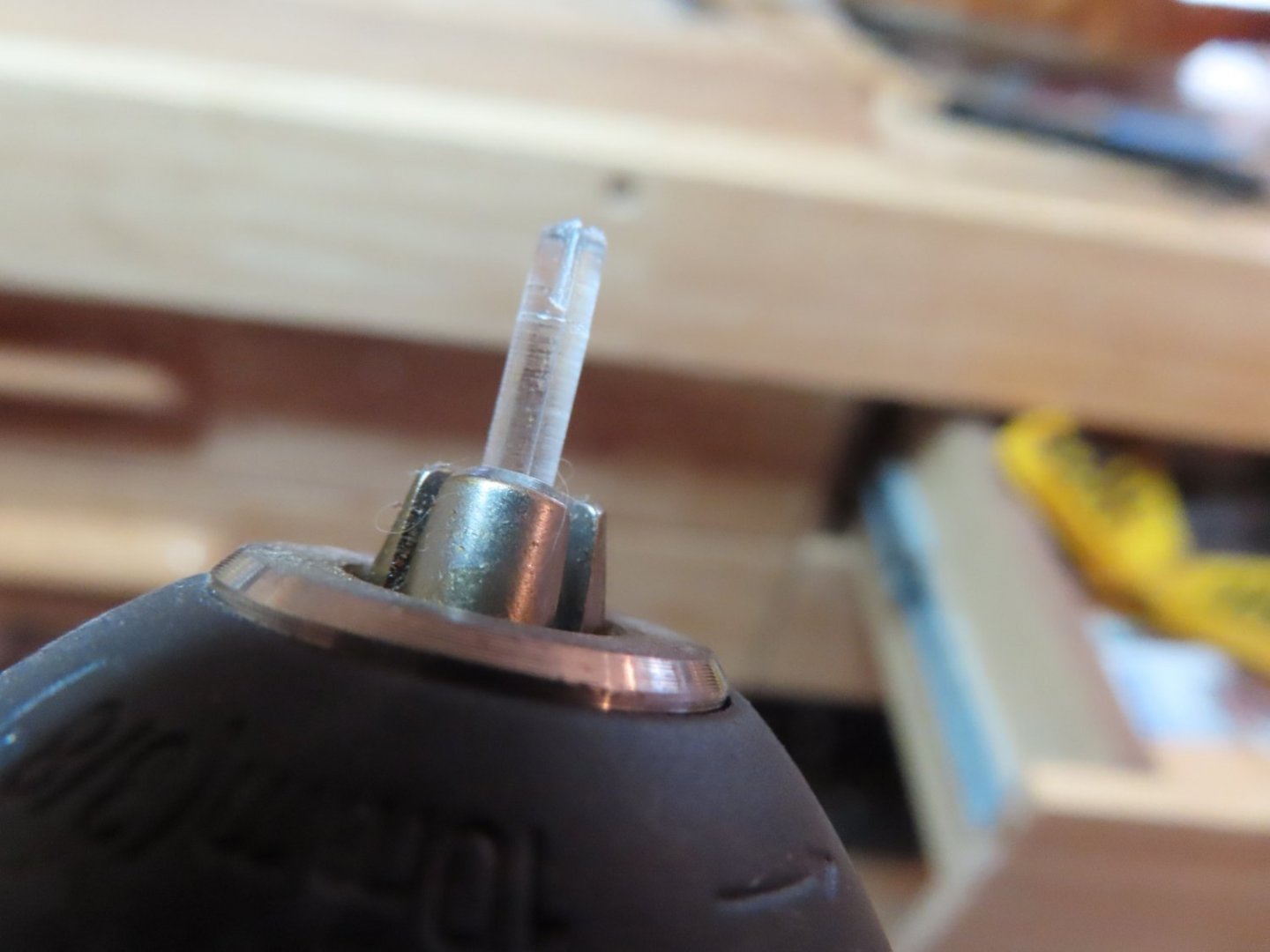
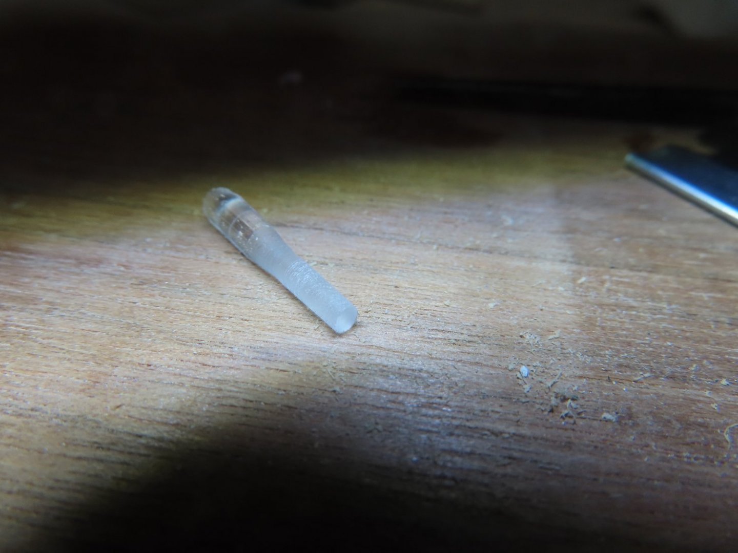
Port Holes There are port holes the on either side of the gun ports. After the hole positions were measured, they were drilled in. I didn’t want to leave the holes open so used a piece of clear plastic from an old car model’s parts tree. Using my Dremel drill as a lathe, I filed the plastic as it was spinning in the drill till it obtained the proper hole diameter. I sliced off two pieces and when placed into the porthole openings, they had a nice snug fit. No glue was necessary. Voila, “glass” portholes.

-
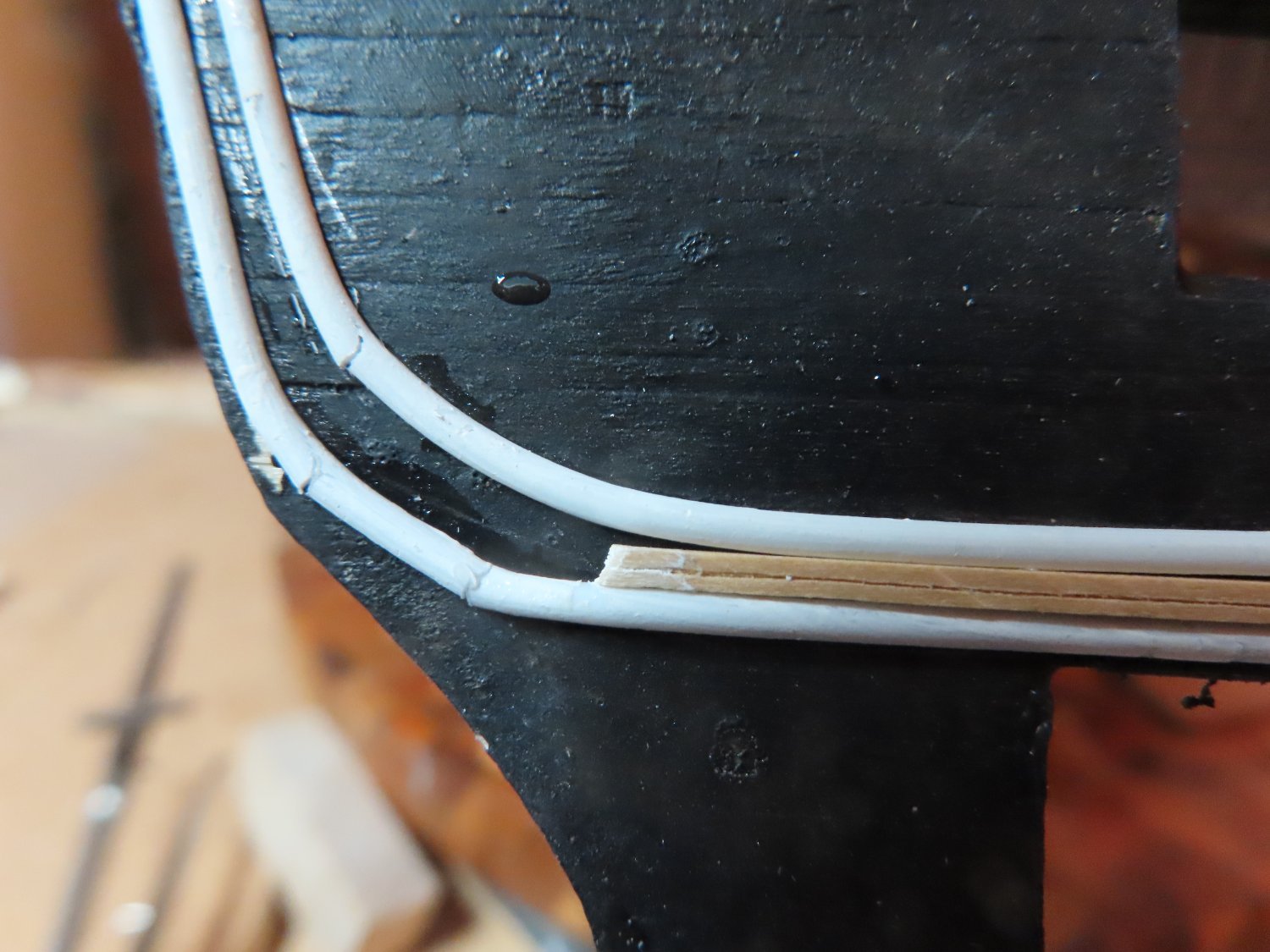
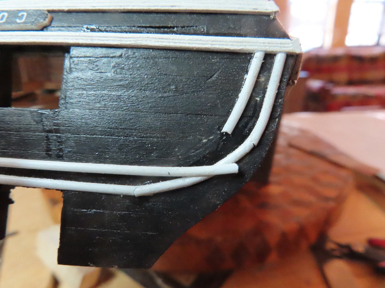
I remember someone had commented somewhere on another build log that one should paint the white styrene, white. He claimed that over time the plastic tended to yellow a bit. I also find that the styrene has a sort of translucent look to it, so it doesn’t quite match the look of the white paint wood. Therefore, instead of using the Styrene molding strip straight from the package, I painted it white. I also tried to pre-bend the styrene to give it some bend memory to make it easier to install. I bent the plastic to shape and held it overnight. I wanted to heat it as well, but my hair drying just didn’t get hot enough. In the end, the pre-bending didn’t help that much. Following the practicum, I CA glued the transom gluing a little at a time while bending it. What did surprise me was the effect CA glue had on the plastic. It made it brittle and made the plastic break as I was bending it as shown in the images below. The broken pieces were repaired and glued back into position. Please note, the piece of wood between the styrene strips was used as a spacer.
-
Transom Trim Continued Double arch The practicum chose not to use the laser cut double arch molding because they: Became very fragile once removed from the laser cut board Were square cross section whereas the actual molding is half circle cross section Were difficult to shape and sand As much as I wanted the trim to be made from wood, it was much more practical to follow the practicum guidance and use white 0.060" half round styrene. Like the practicum directed, I used the kit's laser part to pencil in a faint line across the transom where the styrene piece was to go. By holding the laser cut piece in place with one hand, I traced around one edge with the other marking the curvature on the transom with a pencil which you can just see in the second image. The first image below shows the actual transom as a reference.

-
Very nicely done. Just be extra careful once the gun port lids are installed onto the hull. I would wait until the last possible moment before installing them. The open lids are fragile and are easily knocked off. Are you going to paint the interior face of the lids black like the contemporary images show? Jon
-
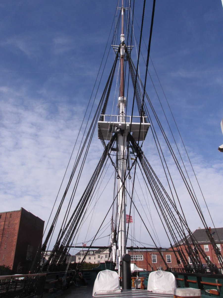
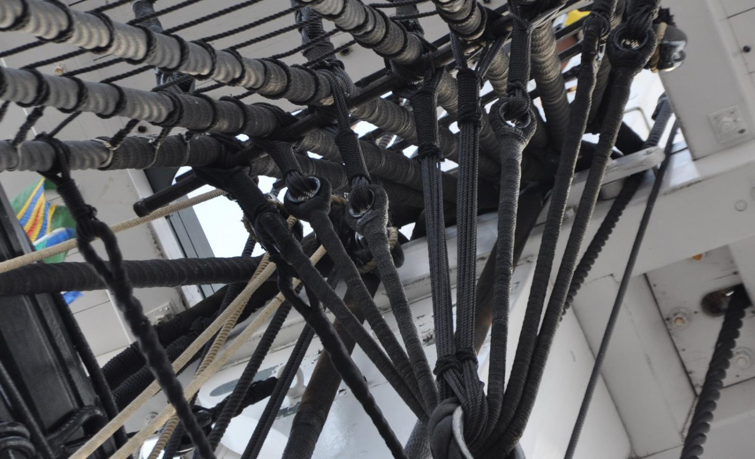
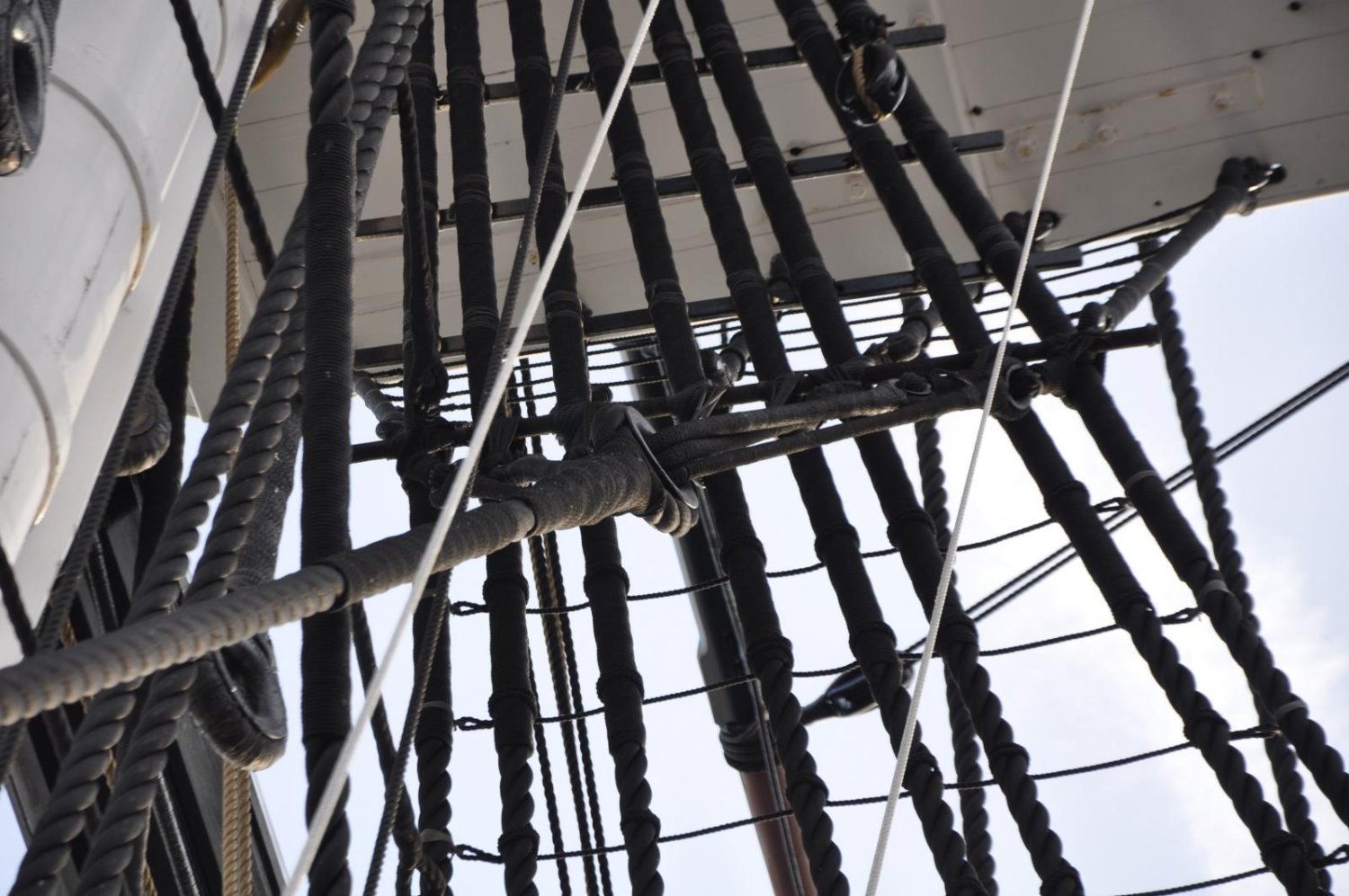
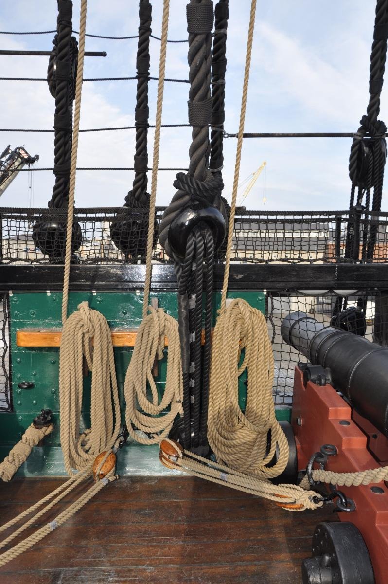
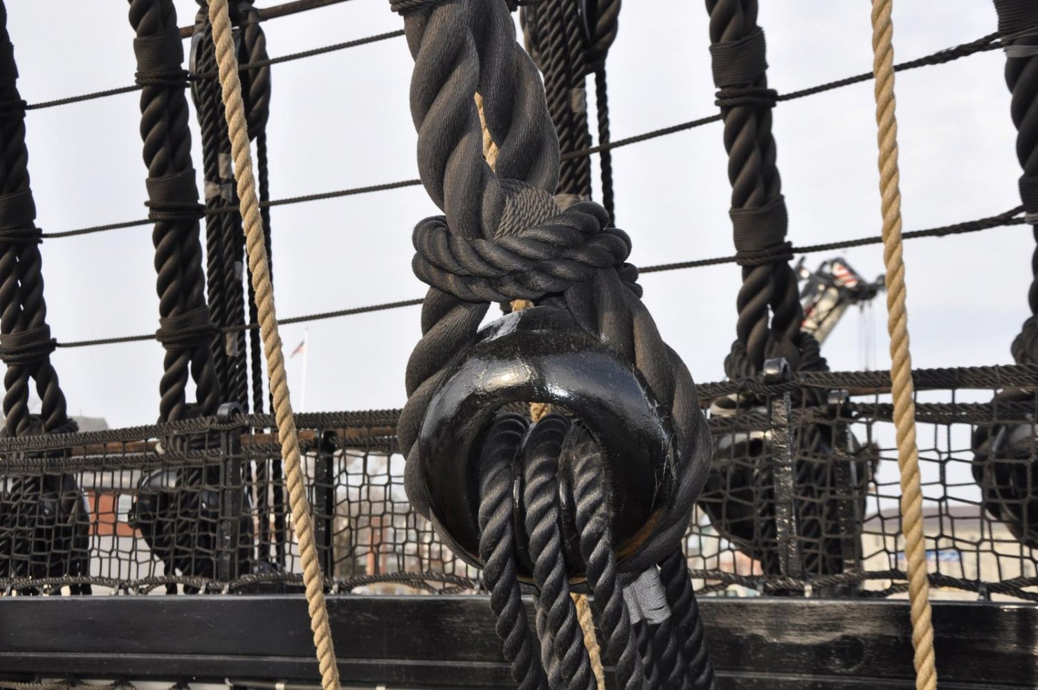
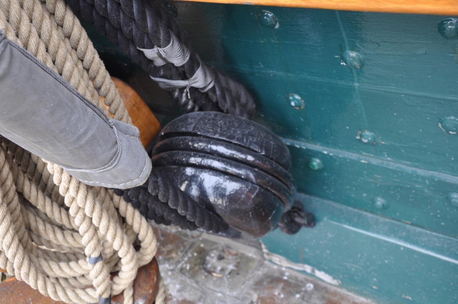
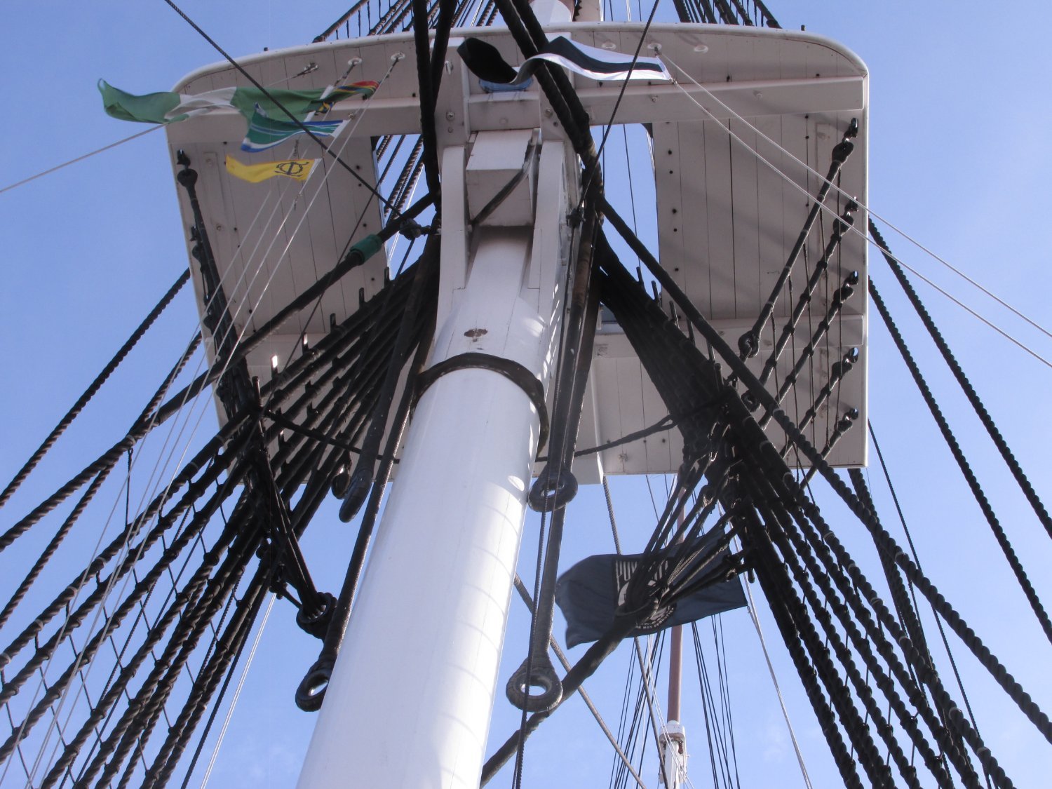
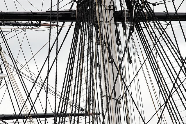
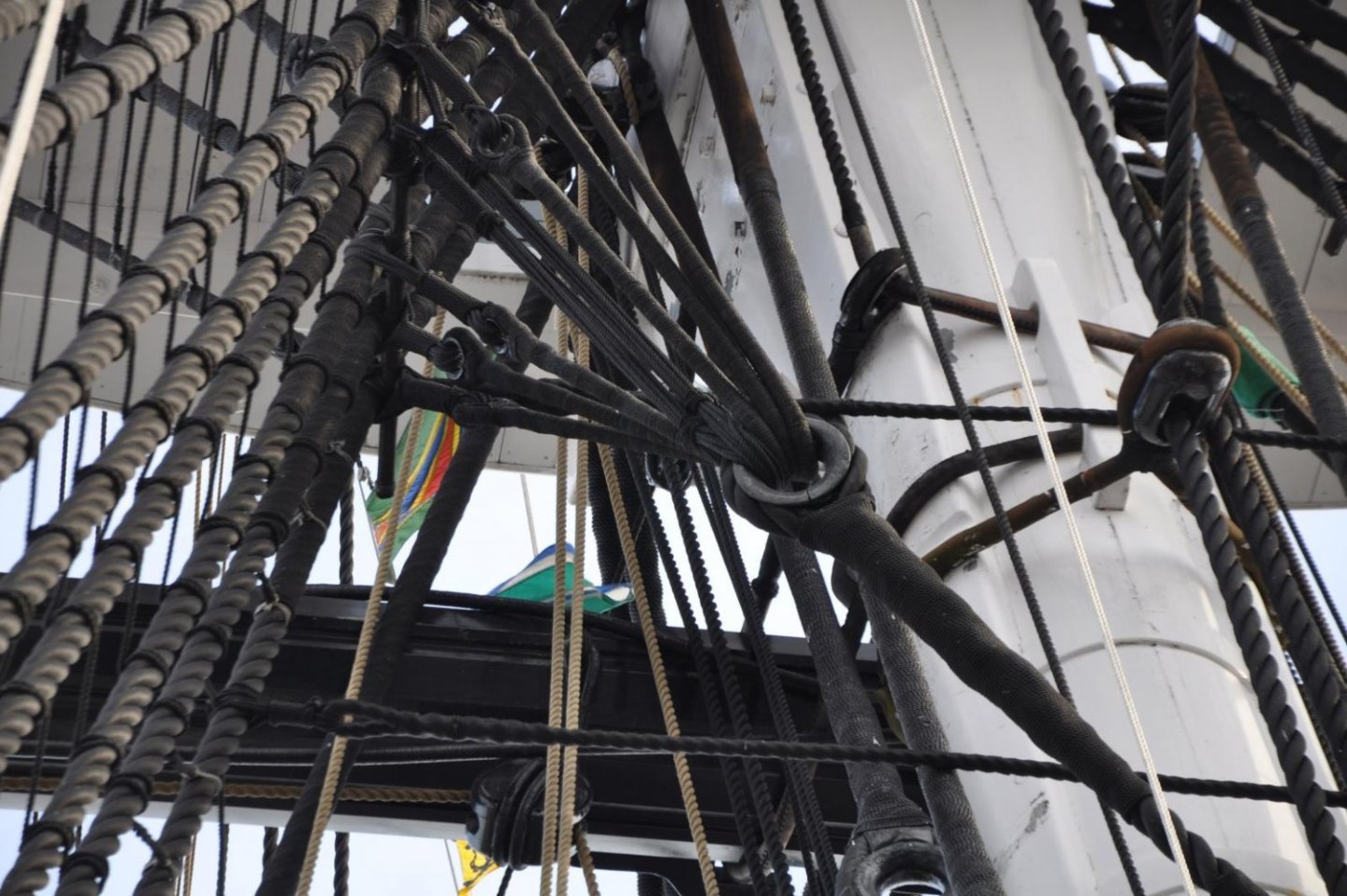
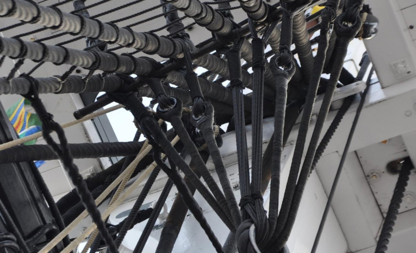
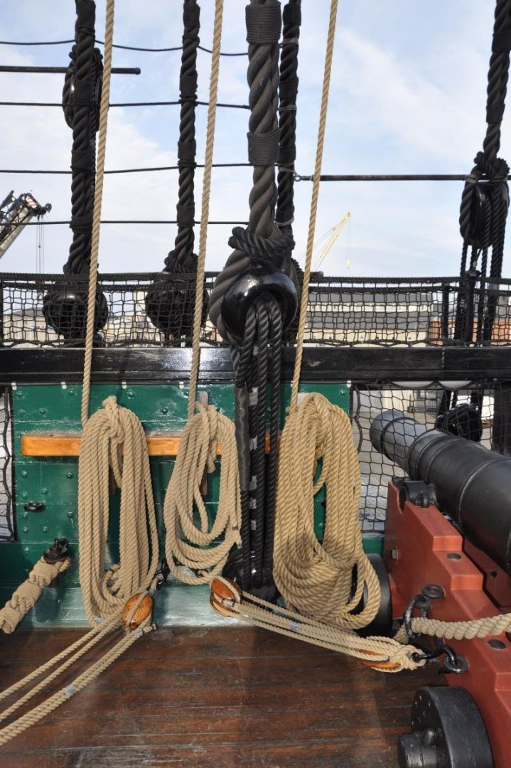
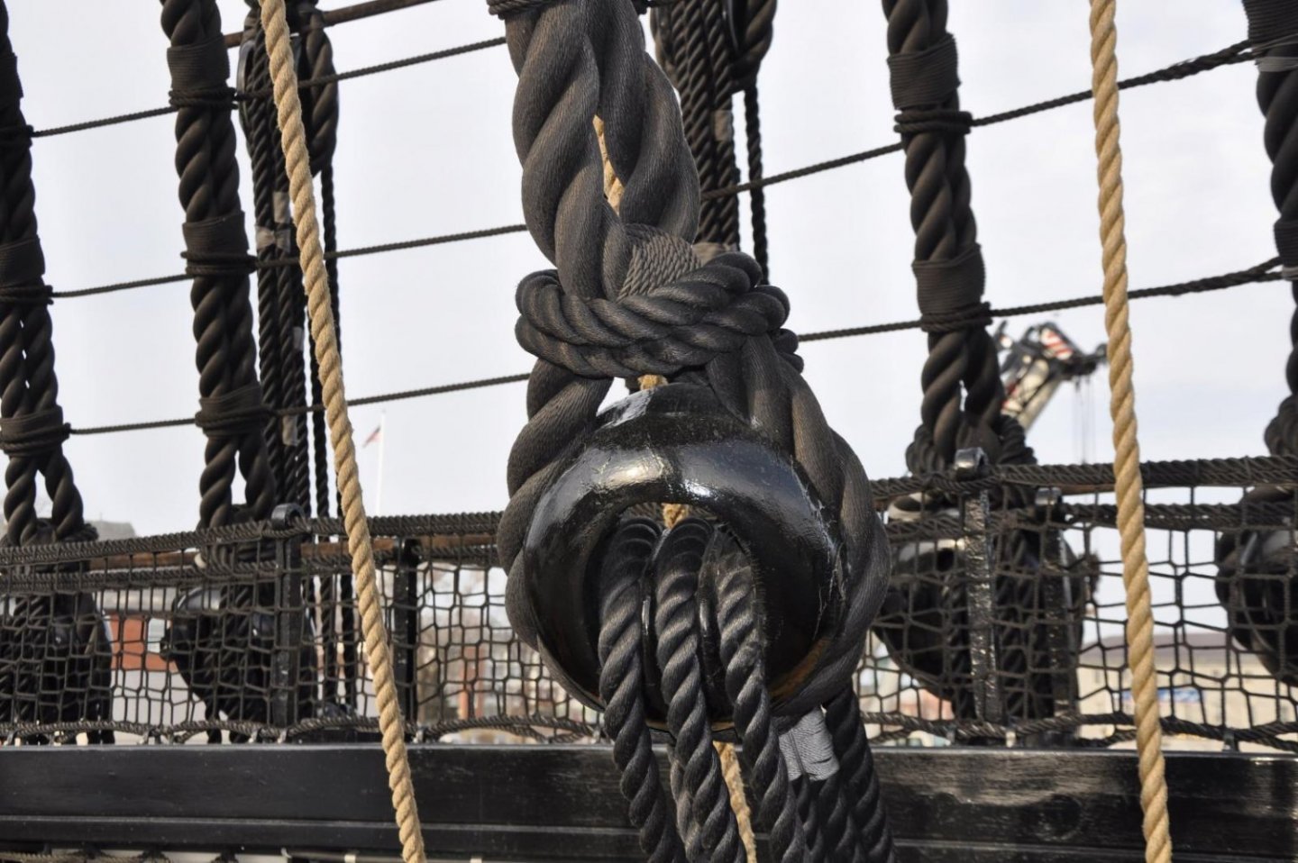
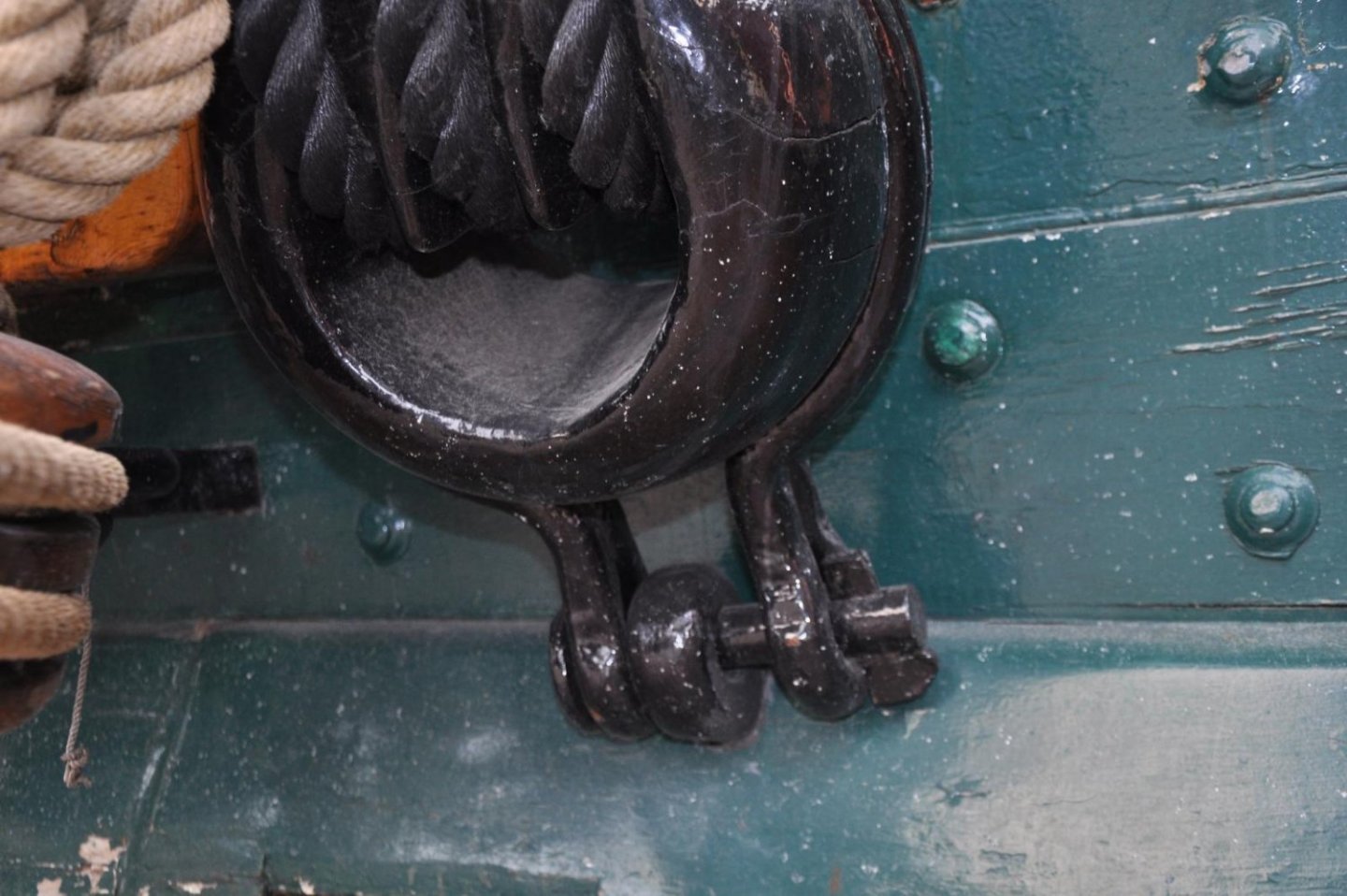
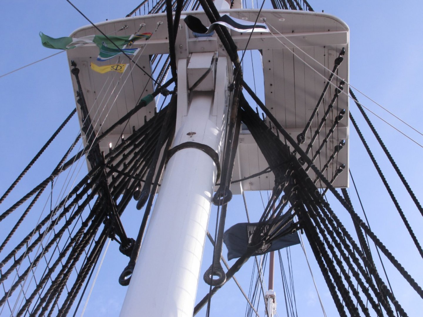
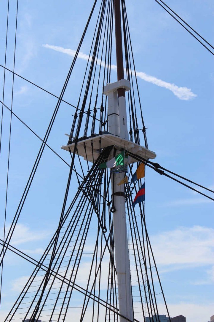
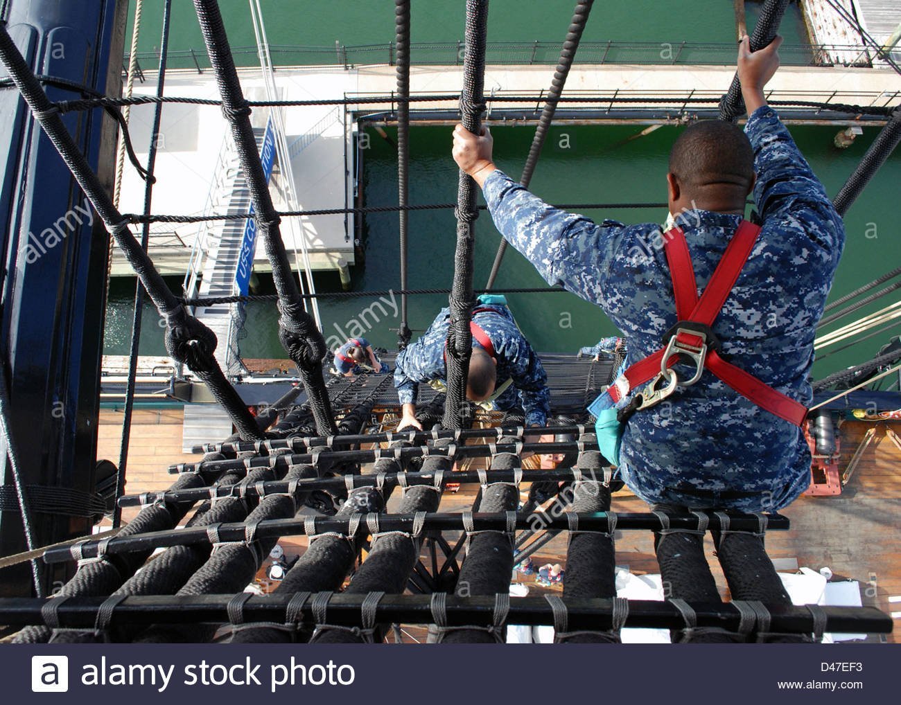
Tom, those "heavy lines which end in thimbles are called Burton Pendants. From David Antscherl's book, "The Fully Framed Model, Rigging a Sixth Rate Sloop of 1767-1780" Vol IV: “Burton Pendants are served lines that were slipped over the mastheads prior to stepping the lower masts in full-sized practice. Blocks and tackles were then attached to them for hauling up to the tops and other items of rigging.” They are an essential part of the ship. I have collected a vast photo library for my build of the Constitution. Here are some images of the bentinck shroud rigging and burton Pendants that I have. Jon


- 163 replies
-
- 2
-

-
- Model Shipways
- Constitution
- (and 2 more)
-
Thanks Bob
-
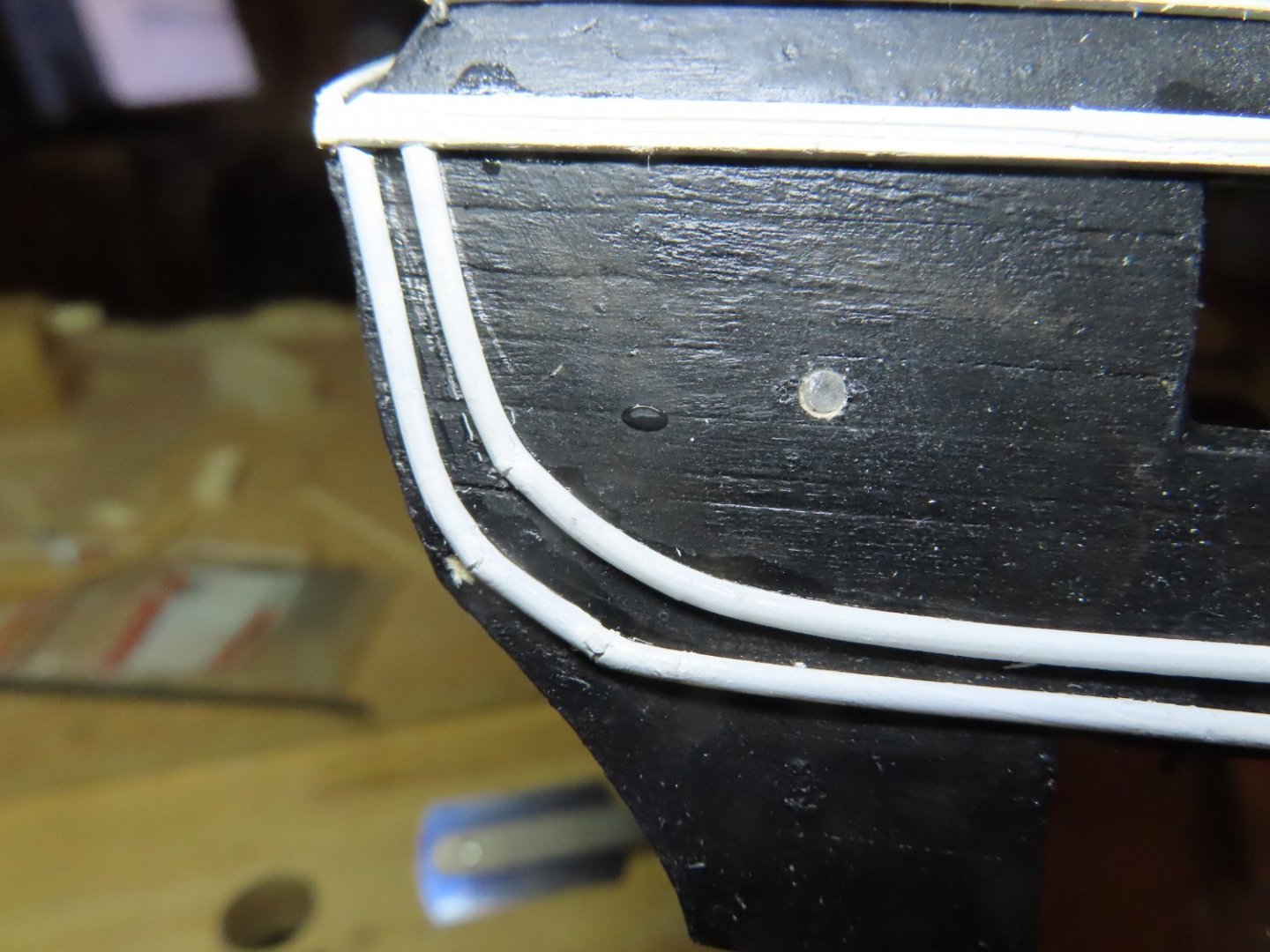
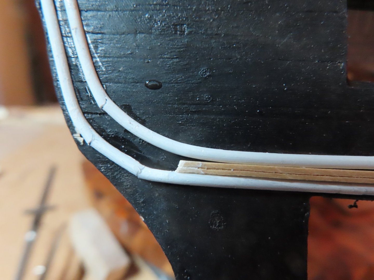
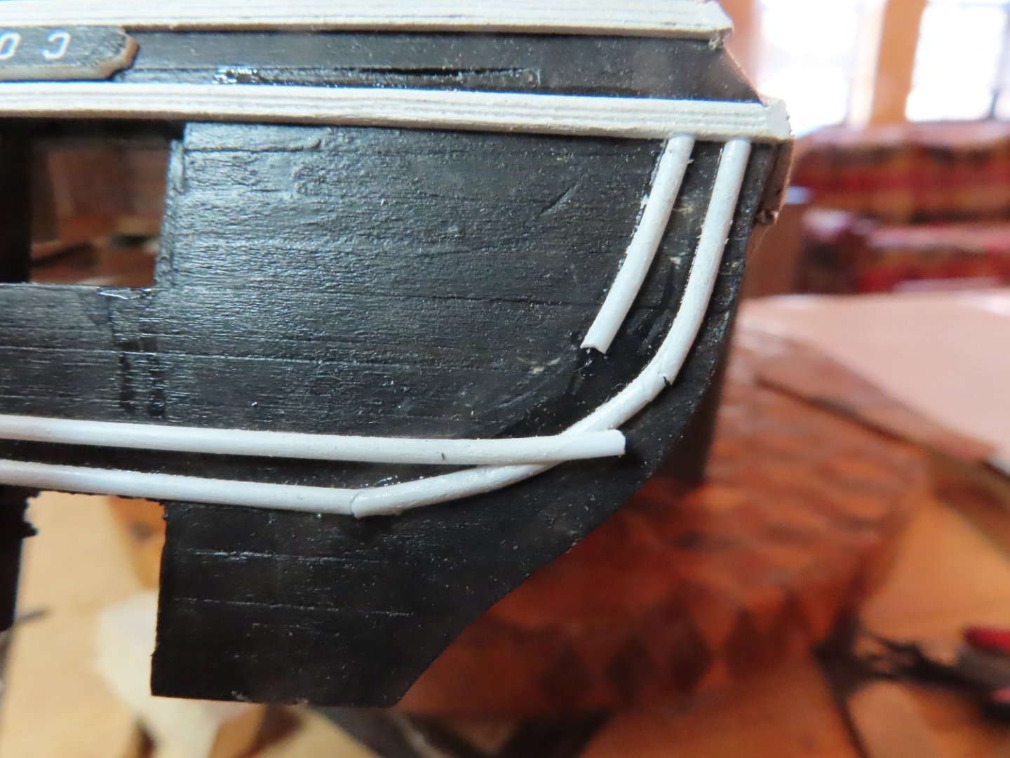
Next, the lower decorative moldings were added to the quarter galleries which no flat surfaces. To make them wrap around the galleries, they had to be bent both horizontally and vertically which was a bit tricky. I’m not proud of the craftmanship, but it’s what I got with the skills I have. It could have been better, and it could have been worst. It’s what I now have. There is still a bunch left to do on the transom, but at least they are on a relatively flat surface.

-
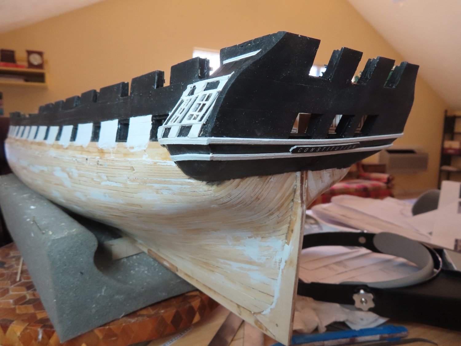
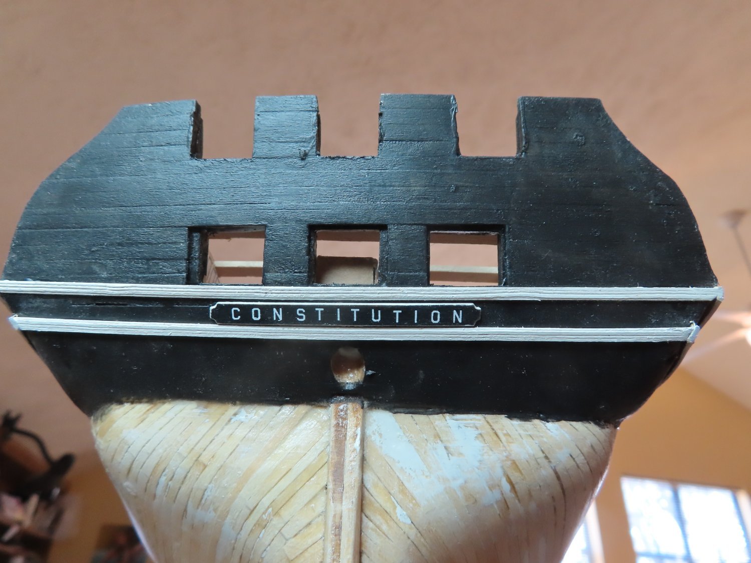
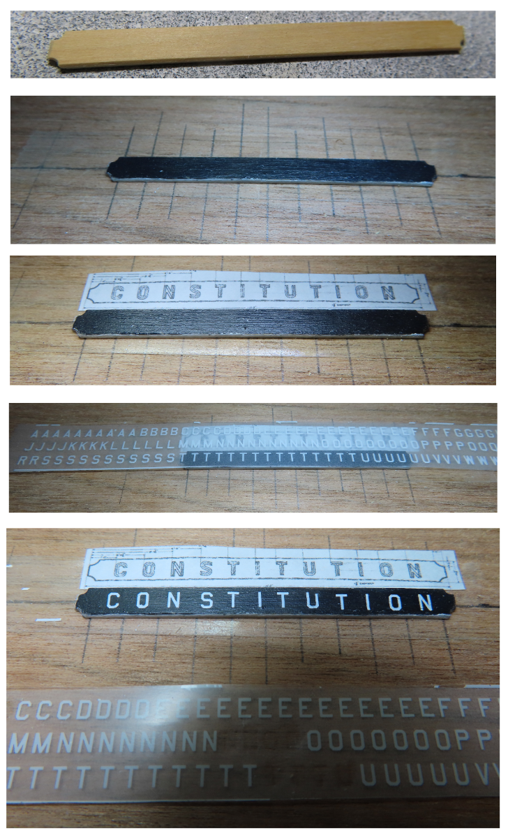
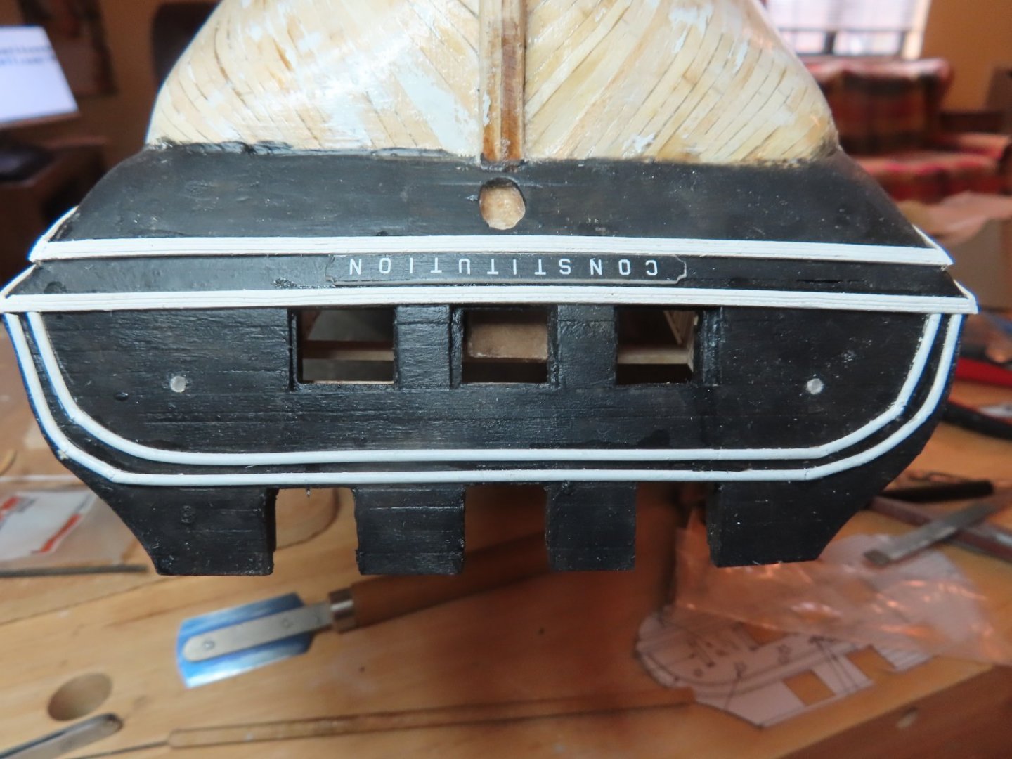
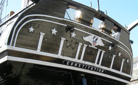
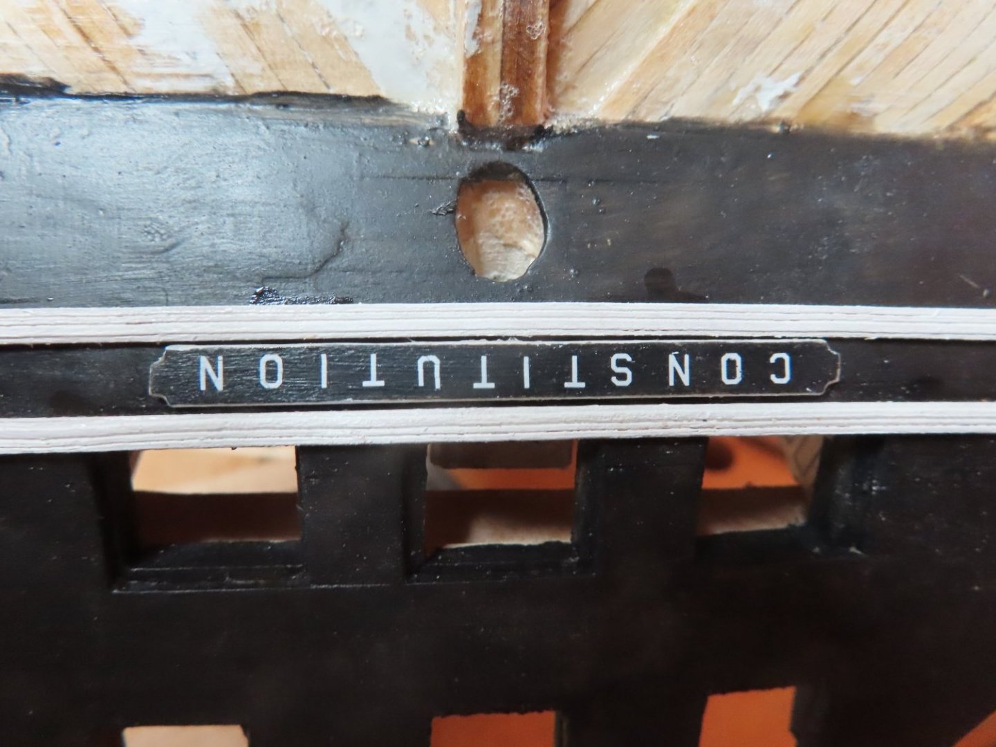
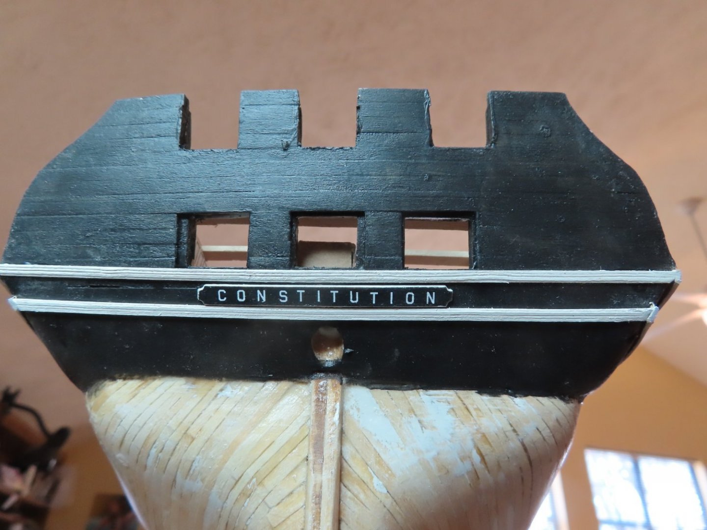
The name plate was glued to the transom on the centerline just below the first decorative molding. A second molding was made for the transom and quarter galleries and applied directly below the name plate and wrapped around to the galleries. (Note, 1st image was taken when model was inverted)

-
Ship’s Nameplate Separating the lower decorative molding on the transom is the ship’s nameplate. To create this, I used the US Navy plan as my guide. The nameplate shown on the kit’s plans is very close to the Navy plans, but the Navy plans provided the actual dimensions. But like the kit, I had to make compromises due to scale issues. In the end, I used a 1/16” wide x 1/32” thick strip of boxwood cut to the proper length. The corner notches were filed in, and the side were beveled slightly. With a couple coats of paint, the edges were painted white and the face black. Finally, the face was cover with a clear coat of Minwax Polycrylic Protective Finish for a smooth finish. Following the instructions of the practicum, I bought a single sheet, item MG6740, 45° USA Gothic White dry transfers made by Woodland Scenic. This sheet has several different sized white letters and numbers sets. I used the 3/32” set. I bought other different sheets as well which I will discuss when I use them. To transfer the lettering, I drew some guides lines as a visual aid on a piece of wood which was then covered by a length of double sided tape. The blank nameplate and a copy of the name plan (reduced to scale) were then laid on the tape. The plan image acted as my layout guide. All I had to do was burnish the transfer letters onto the nameplate below the corresponding letter on the plan. To make the burnishing a bit easier, I cut the 3/32” set off from the original dry transfer sheet for easier handling. Once all the letters were applied to the name plate, another coat of Polycrylic Protective Finish was applied to protect and seal the dry transfers.

-
The next piece of trim to be added to the quarter galleries was the decorative molding just under the windows. The thing is, the quarter gallery molding must line-up with the transom molding and the molding on the opposite quarter gallery. A length of 3/32” boxwood strip was scraped to create the grooves in the decorative molding. First, the transom molding was installed just below the window/gun port openings Then using that molding as a guide, the quarter galleries’ moldings were installed. Finally, the remaining decorative blocks were added to the quarter galleries. All the decorative boxwood panels, blocks, and moldings were pre-painted prior to installation and touched up later if required.