HOLIDAY DONATION DRIVE - SUPPORT MSW - DO YOUR PART TO KEEP THIS GREAT FORUM GOING! (Only 20 donations so far - C'mon guys!)
×


JSGerson
-
Posts
2,612 -
Joined
-
Last visited
Content Type
Profiles
Forums
Gallery
Events
Everything posted by JSGerson
-
 Very nicely done. Just a point of caution, the gun port lids are very delicate, based on my experience with my Rattlesnake build. They have a nasty tendency to get knocked off due to all of the handling the model goes through continuing the build. Not having reach this point yet in my Conny build, I really don't know if it is better to wait and add them on near the end or do them now as you have because it might not be so easy when all the other stuff is added. Only time will tell. Jon
- 55 replies
-
- 1
-

-
- constitution
- model shipways
- (and 1 more)
-
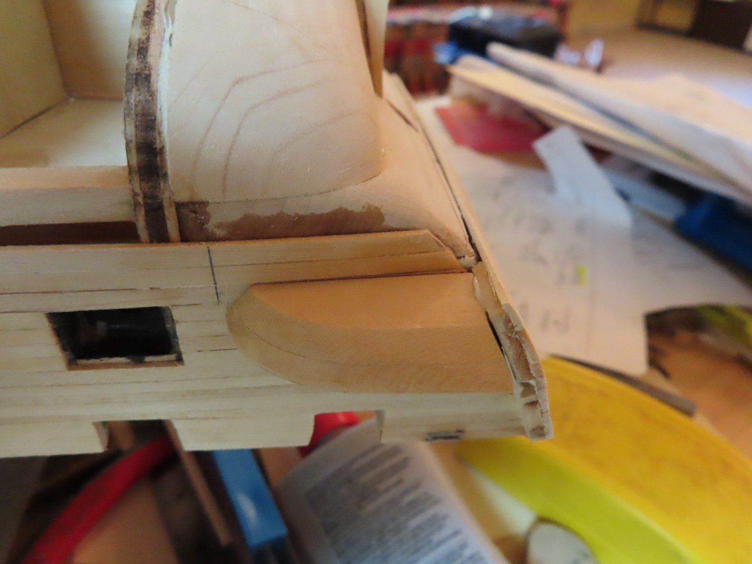
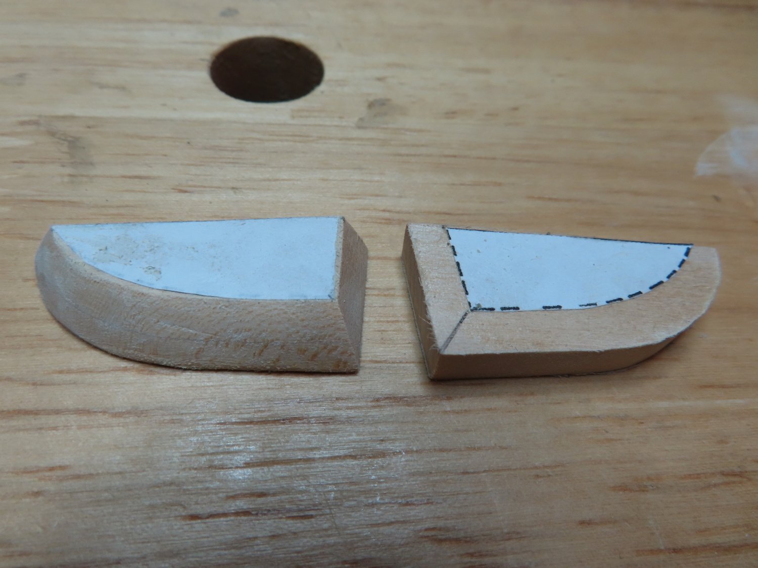
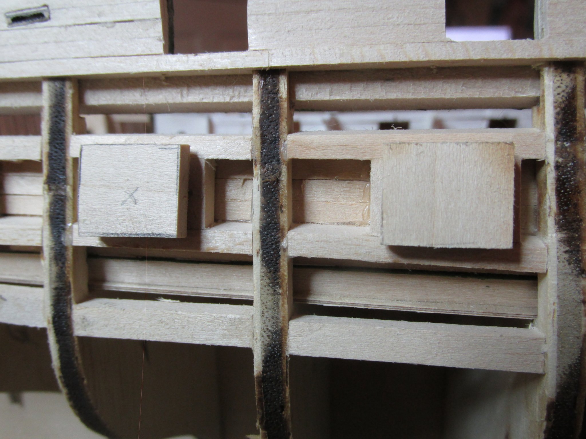
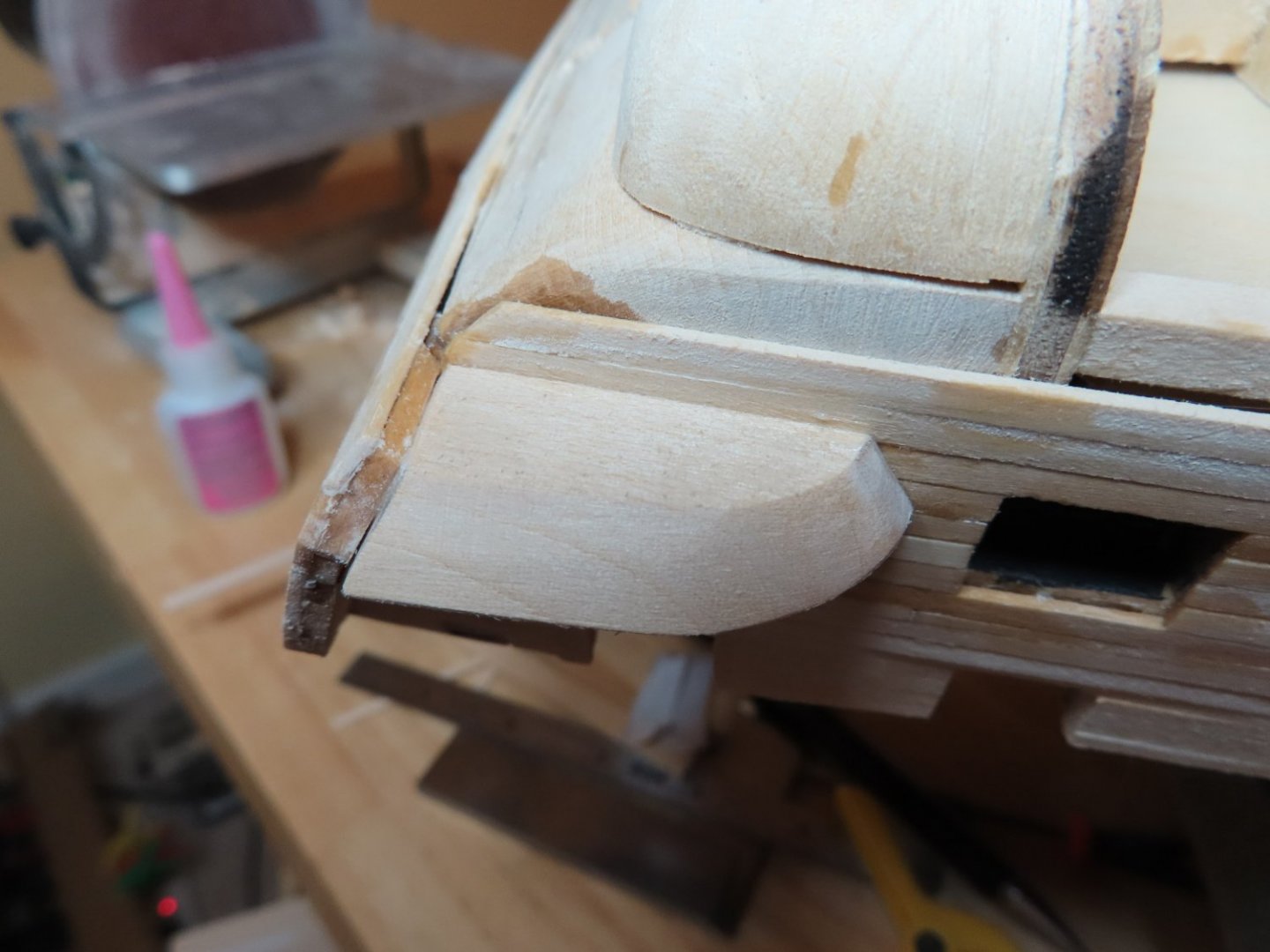
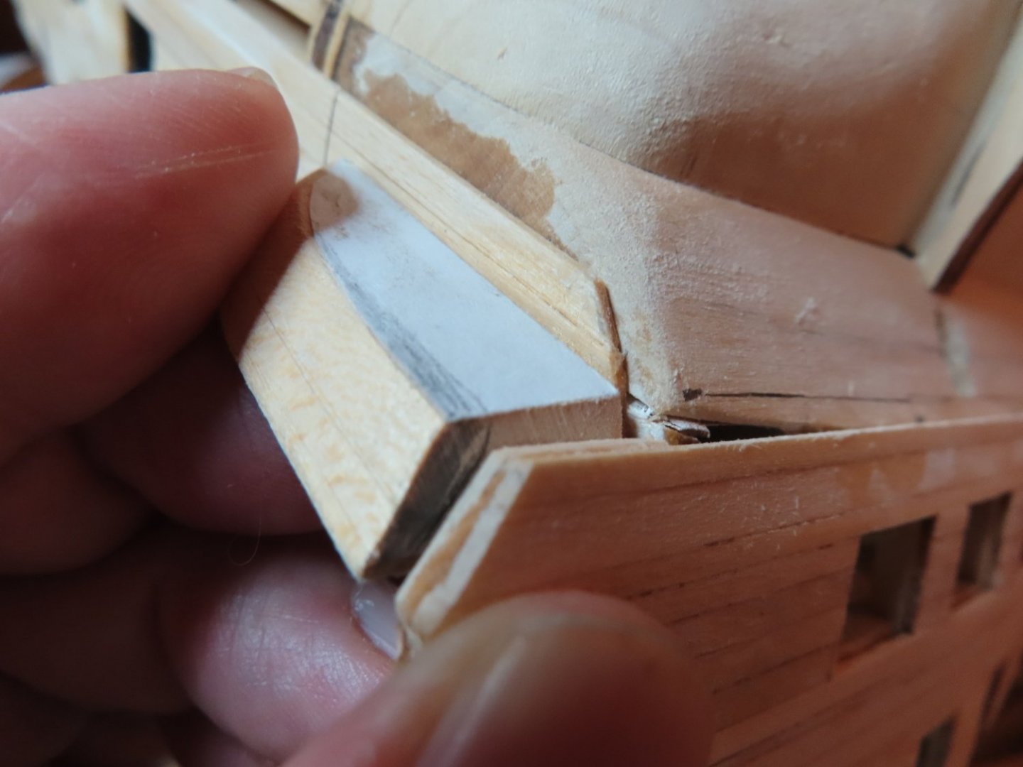
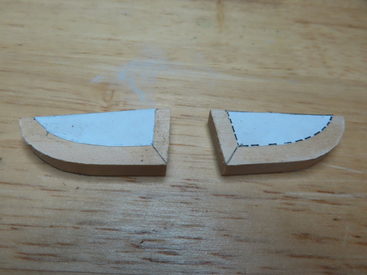
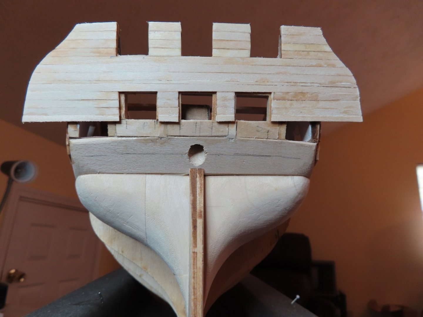
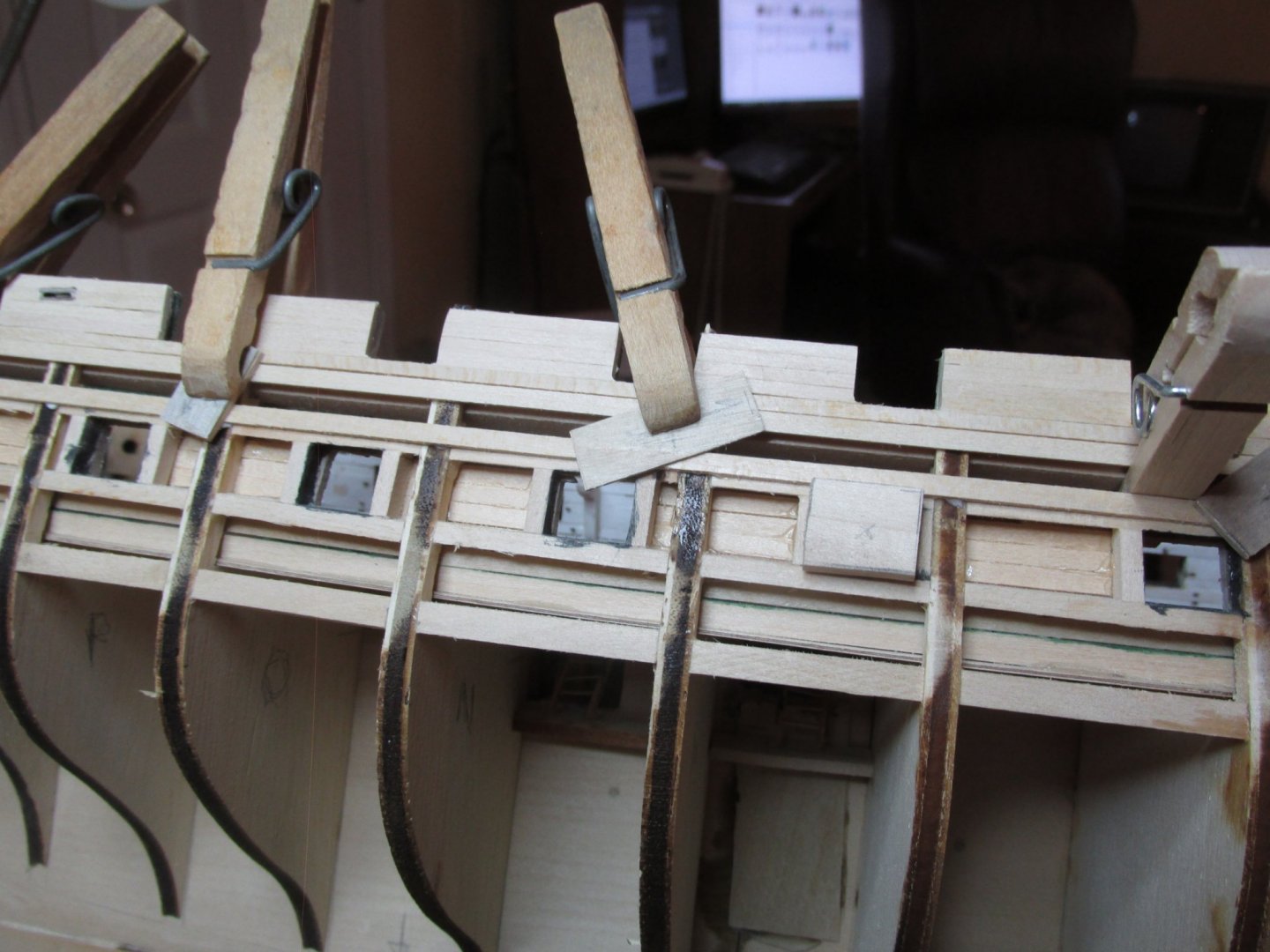
The bottom quarter galley filler pieces were then trimmed slightly and then glued into place as described by the practicum. Hopefully any errors that remain, and I’m sure they do, are small enough that they can be handled without too much consternation


-
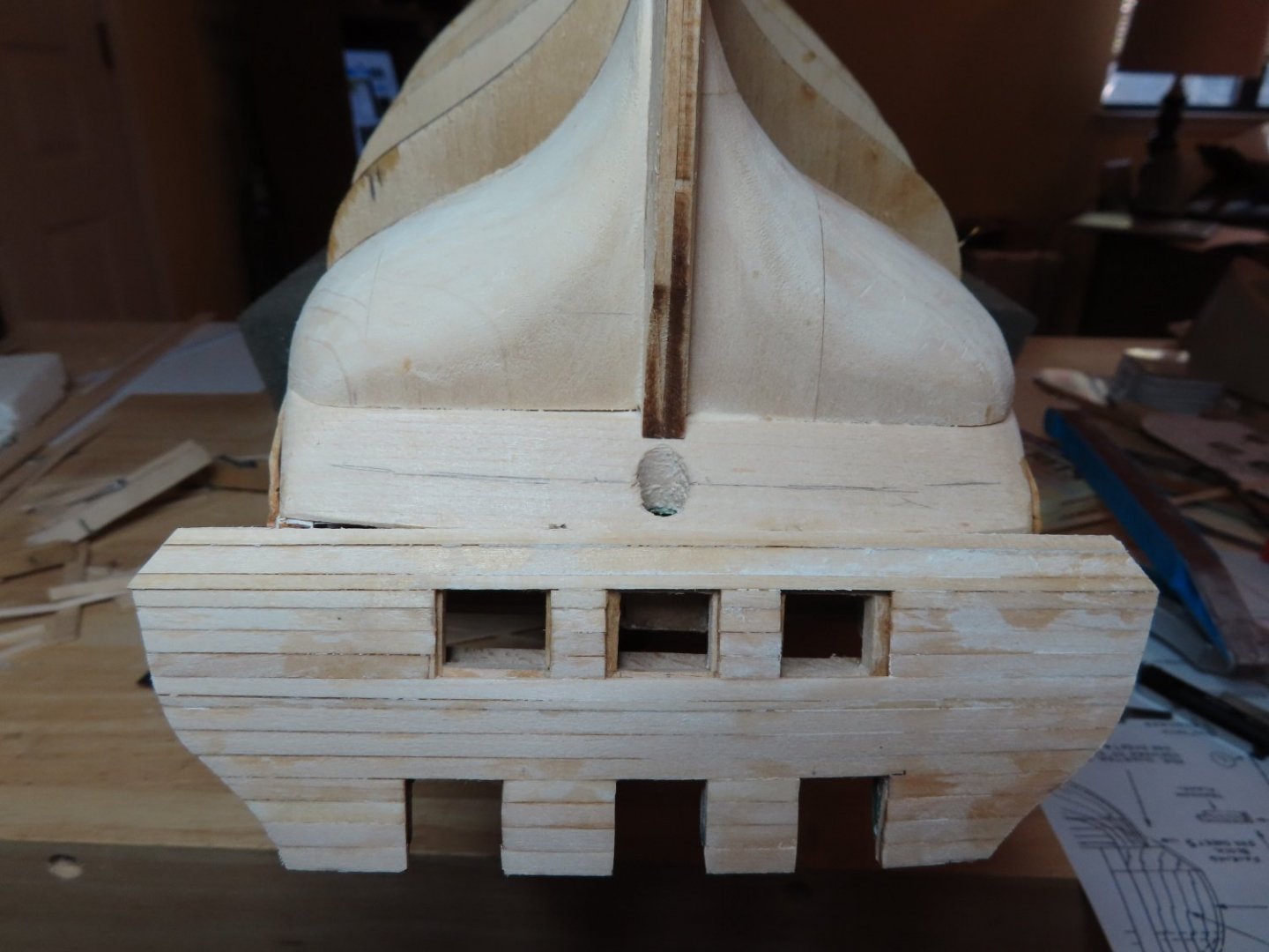
I was able to pry off the bottom two transom planks without too much effort. The new planks were shaped and glued in their place so that at least from the transom point of view, it now level at the bottom edge.

-
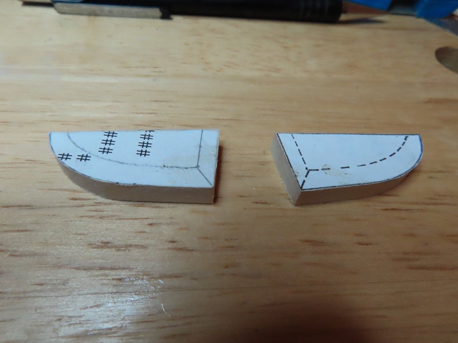
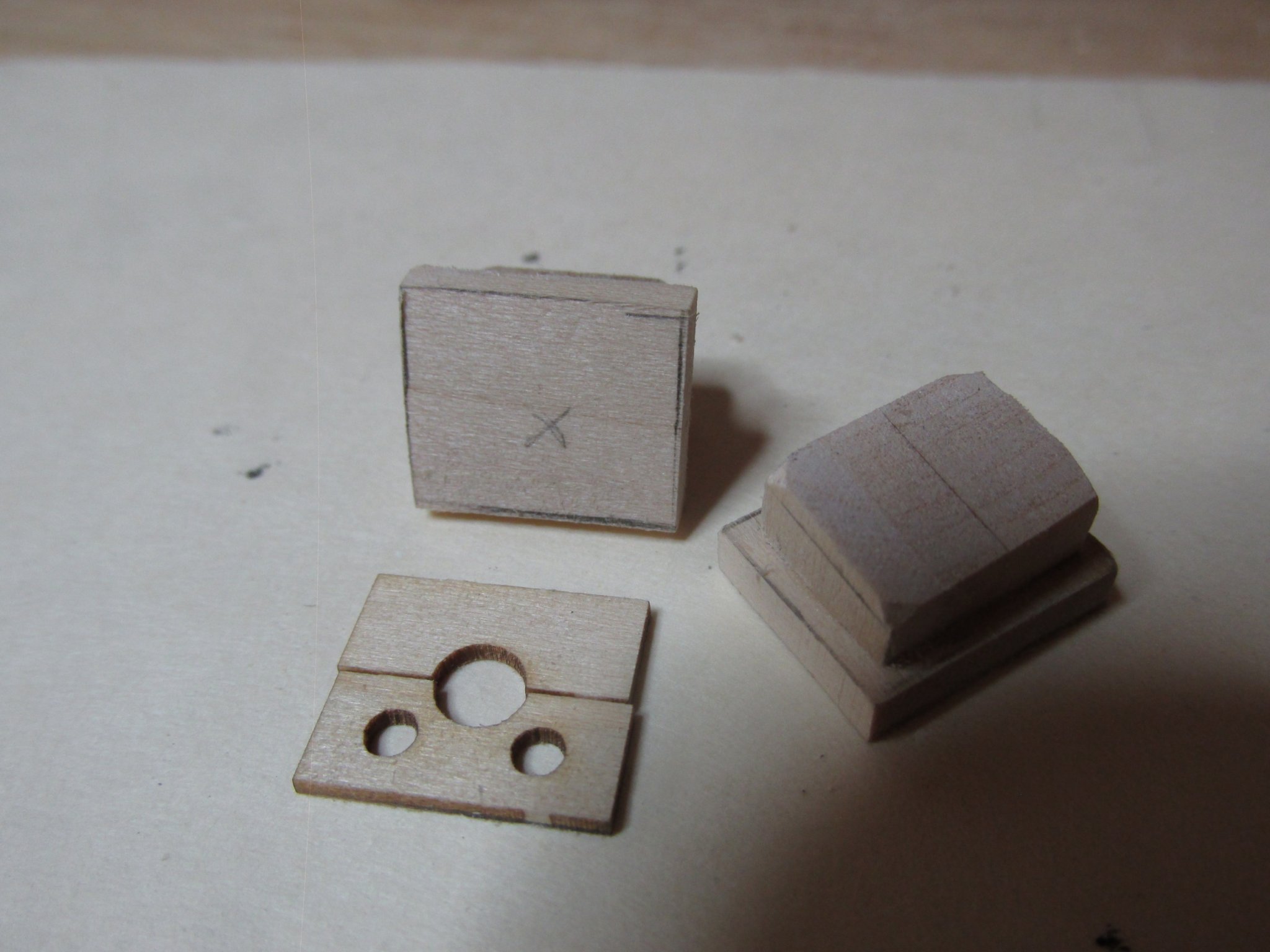
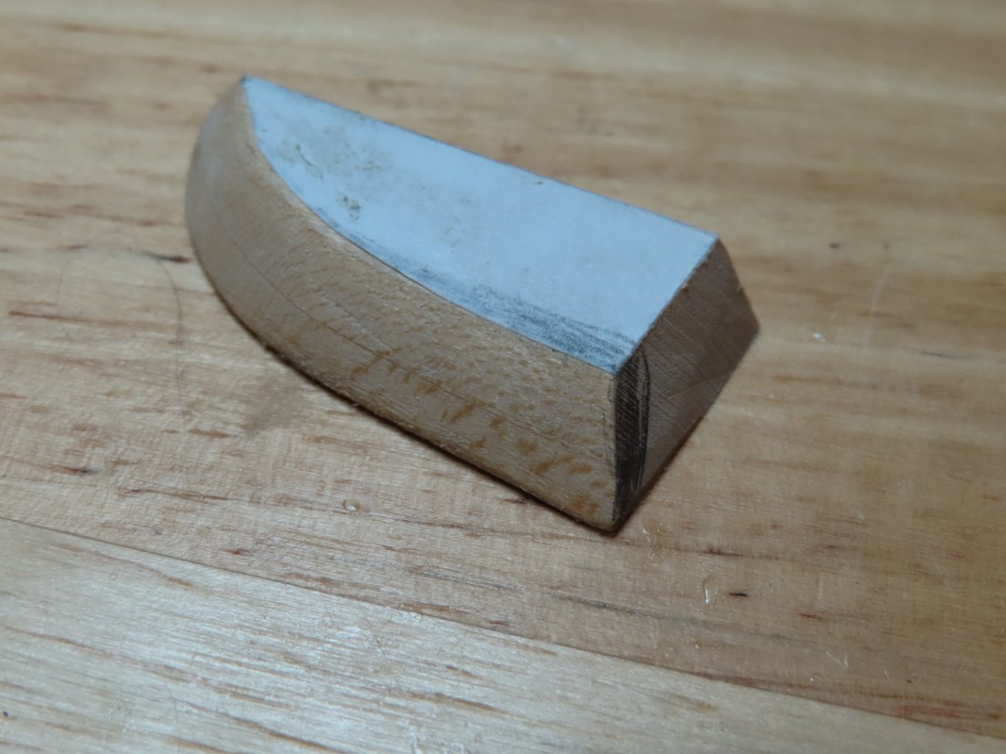
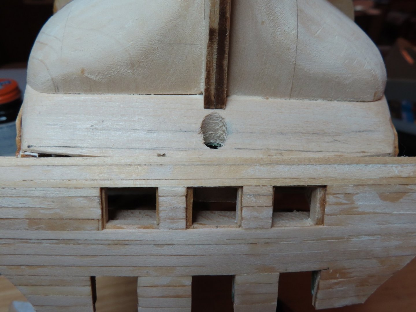
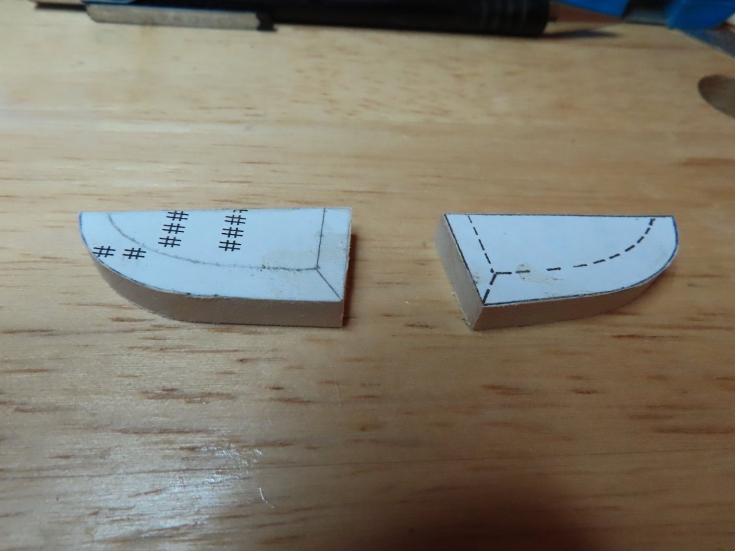
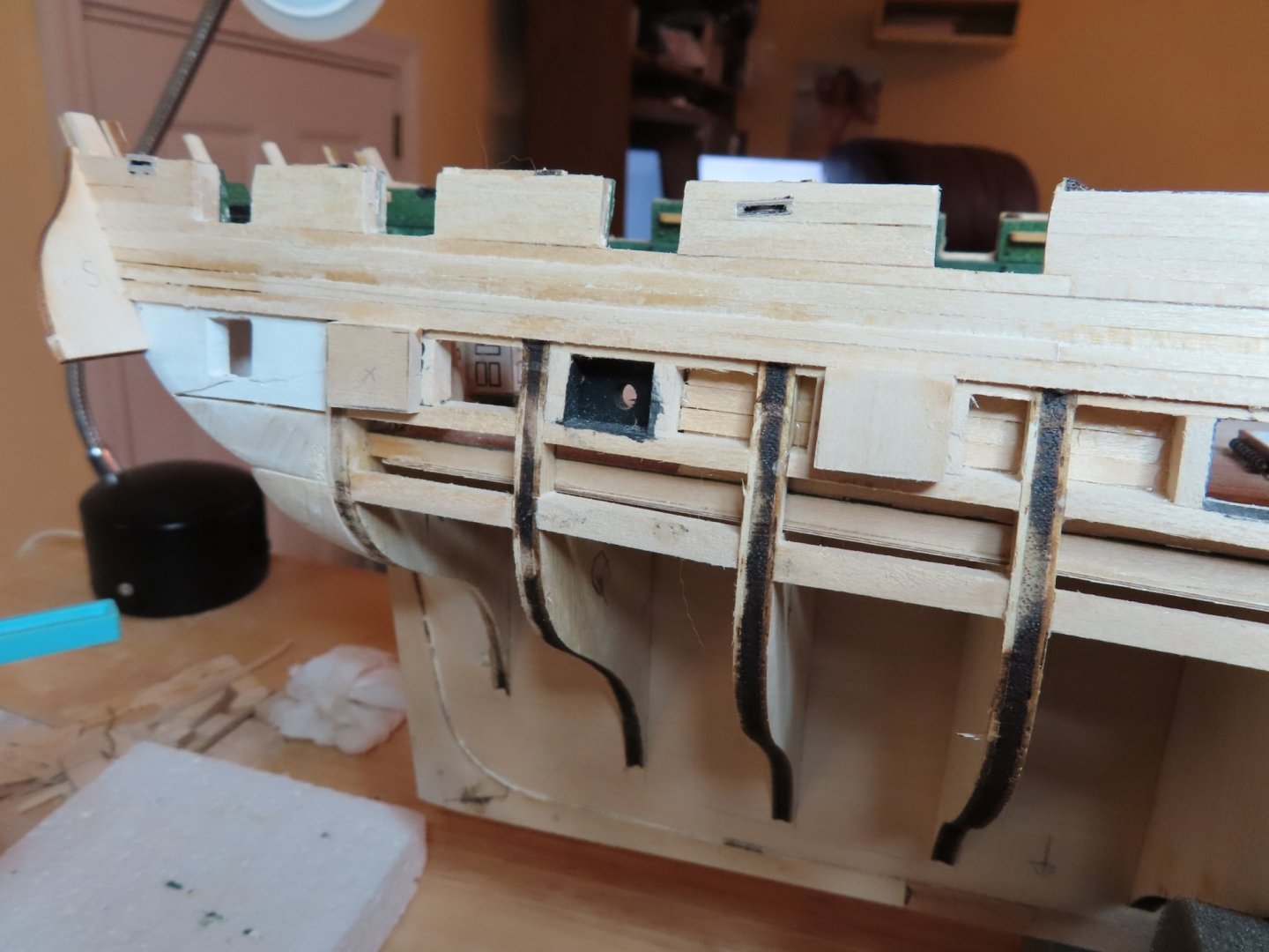
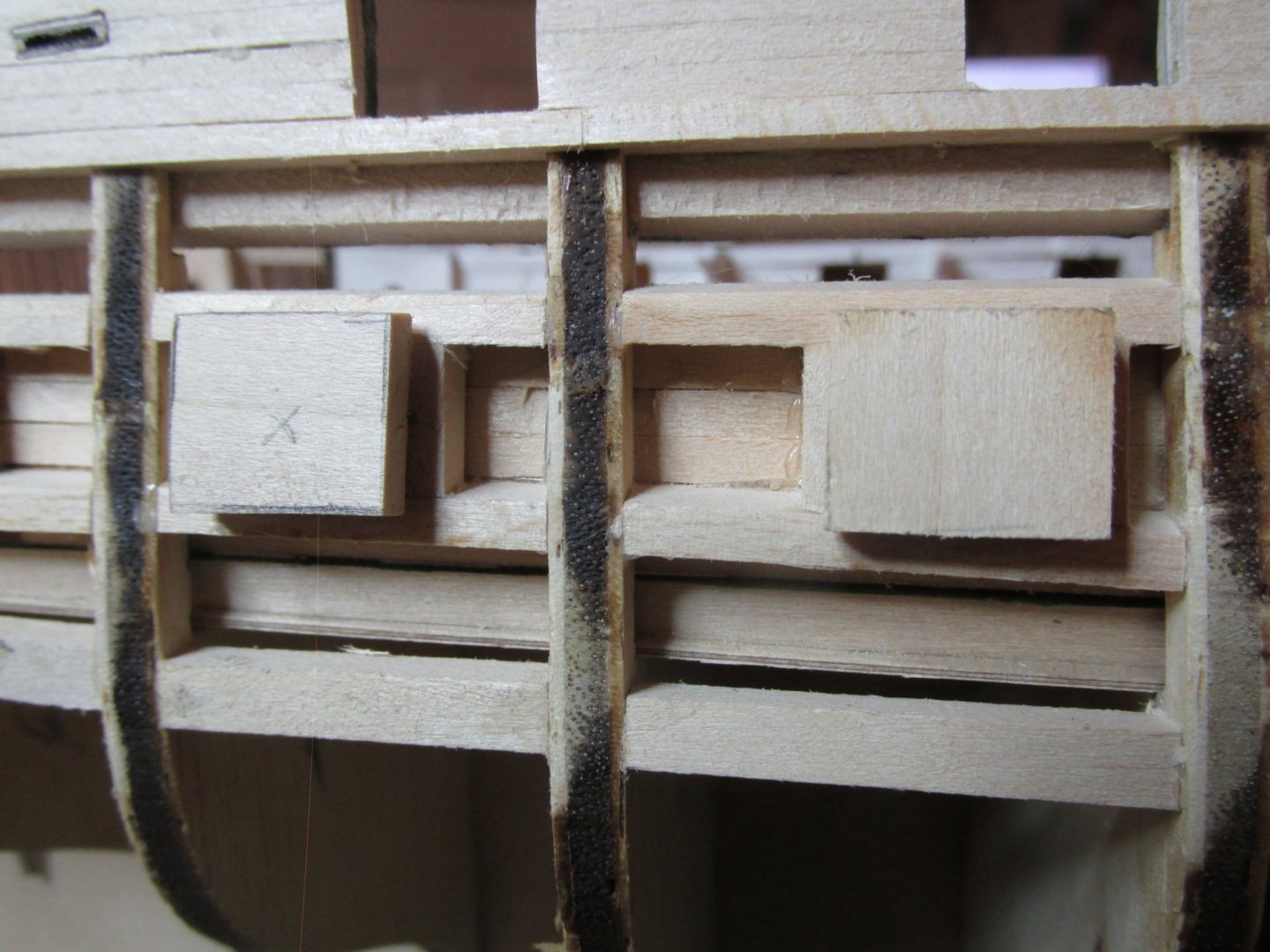
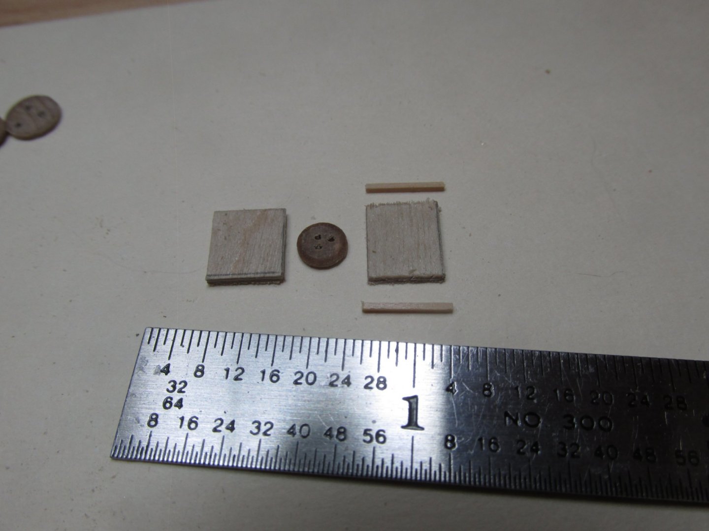
My model is close to following the plans, but not exact enough it seems. The back end of this model has virtually no straight edges from which to measure and the structure is full of curves. My transom seems to be just a bit narrower than the plans so that the filler blocks are a bit too wide to fit as I had cut them out (see my pencil marks on the filler piece). In addition, either my transom is a bit crooked or the area below it is a bit off. See the line I drew just below the rudder post opening. Either way, I’ve got some work to do.
-
That went off without a hitch…so something must be wrong. It’s never that easy. It didn’t take me long to find out what. When I dry fitted the fillers into position, the troubles I had with the transom came back to haunt me.
-
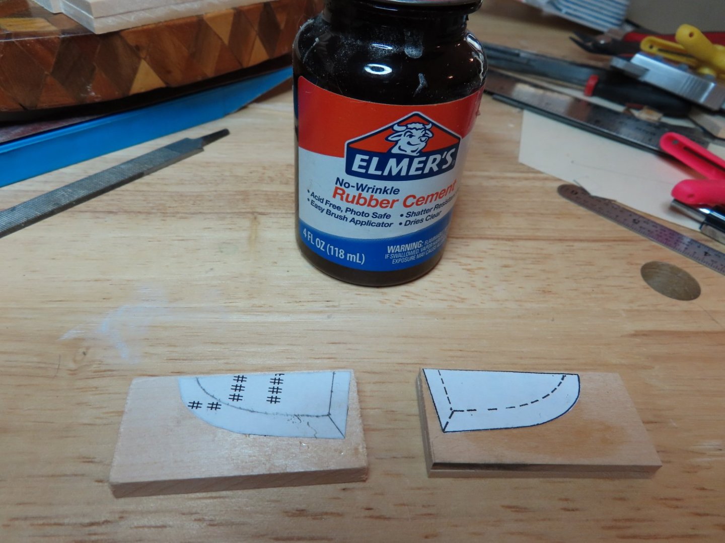
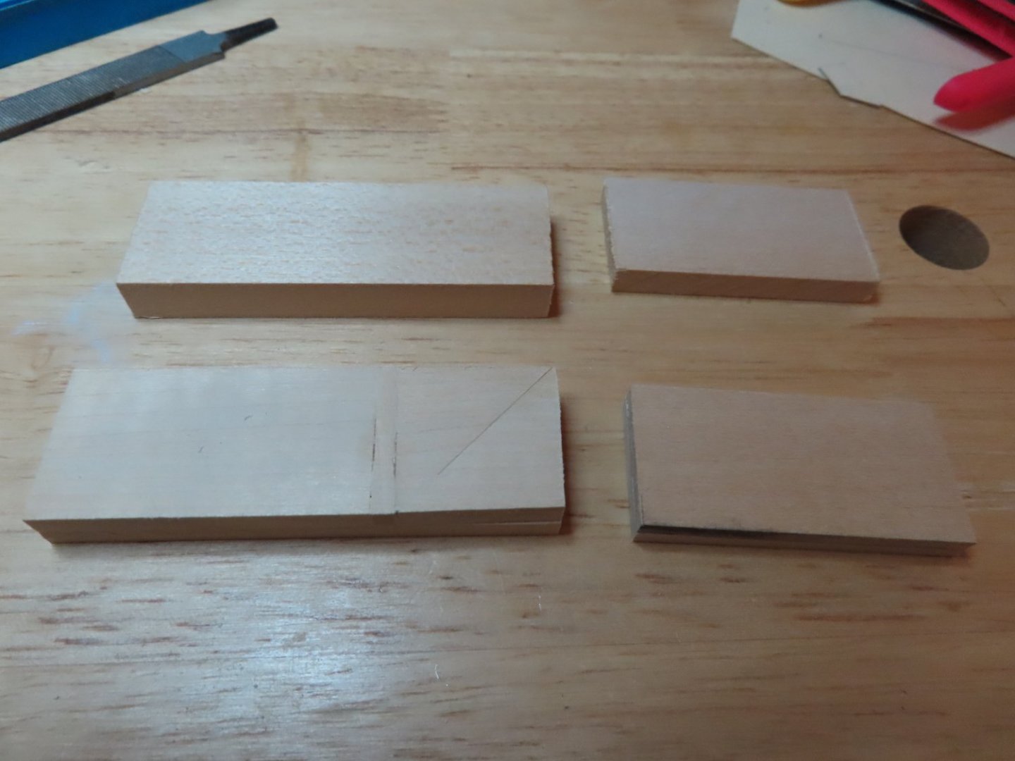
Templates for the bottom filler pieces were made from the plans. First the larger of the two templates and cemented to the billets and cut out. Then a second set of templates were cemented to the bottom of the just cut pieces. Using my disk sander, files, and sandpaper, the bottom filler pieces were formed.

-
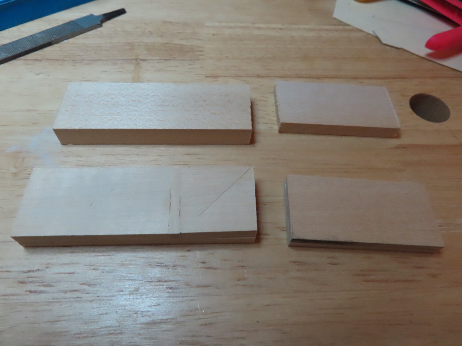
Now for the hard part: The Quarter Gallery Structures. Following the practicum, Mr. Hunt indicated that the kit does not provide enough basswood billets, which I found true. The kit provides one filler block 3/8” x 1” x 3” for the lower side area and one ¼” x 1” x 2” filler block for the upper side of the quarter gallery. That’s only enough for one quarter gallery, there are two. So, he tells the builder to buy more wood. In normal times buying wood is easy, just run down to the hobby store and buy some. But in this newly strange world of the pandemic that’s not possible especially when you live in a small town and all you have is Hobby Lobby. I could have ordered on-line but that adds too much cost due to shipping and you have to wait. However, I did have scrap wood, so I made the additional billets by lamination.
-
That was the easy part.

-
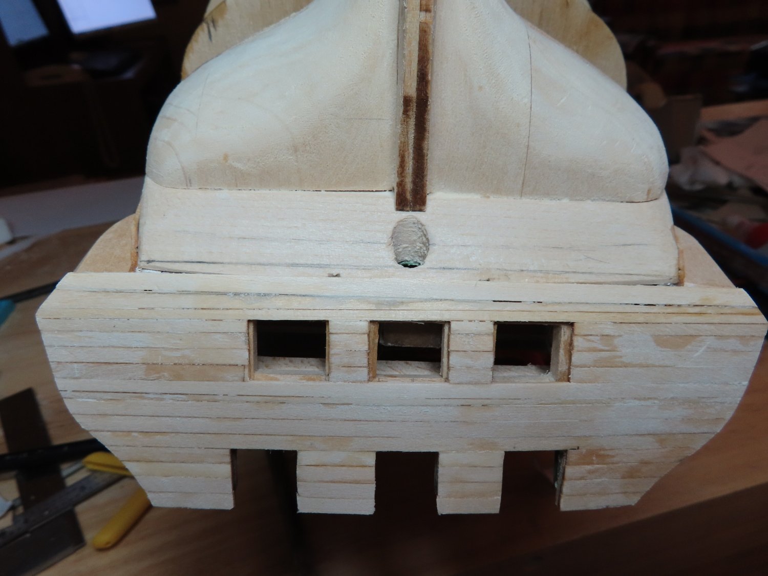
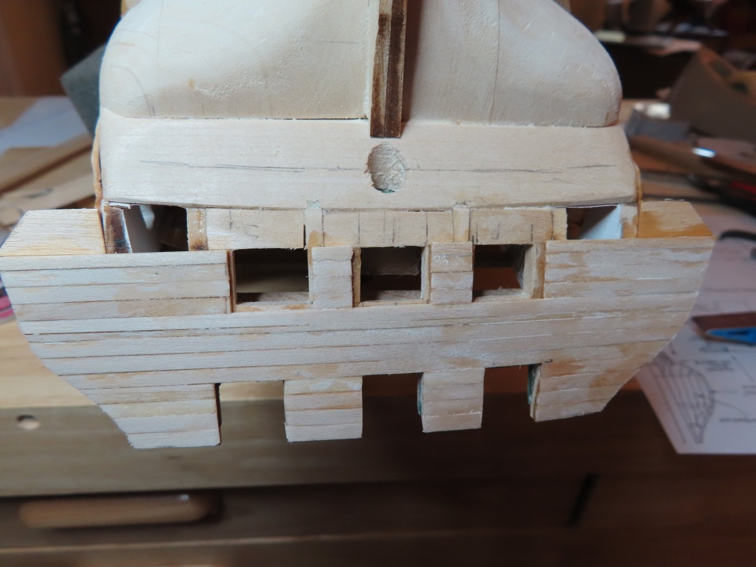
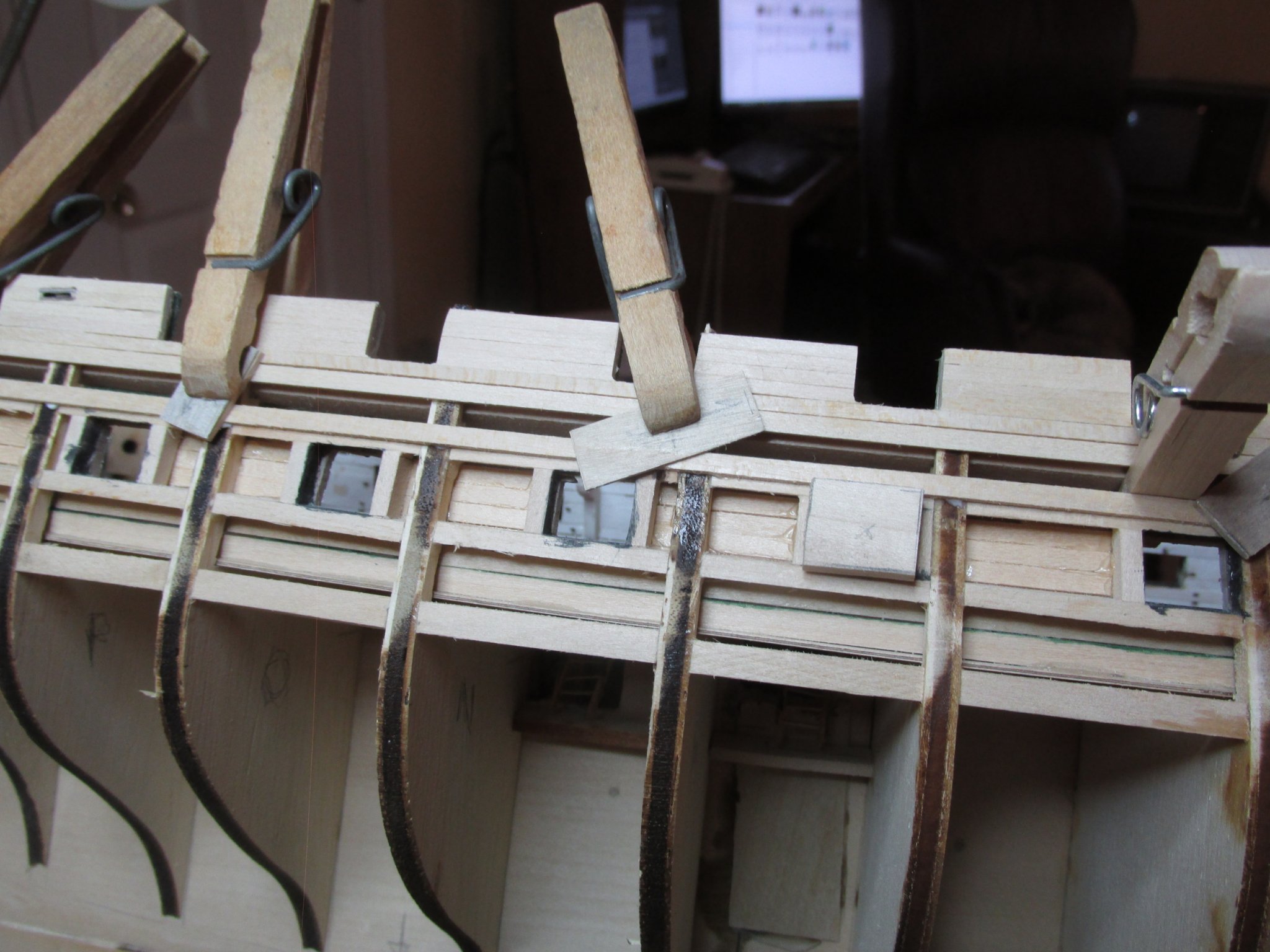
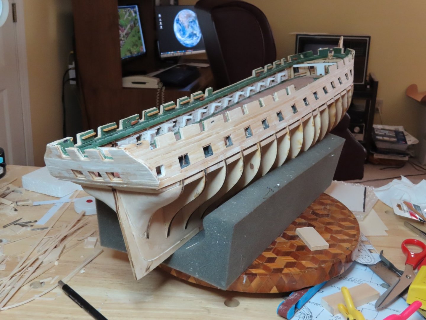
Then the lower transom extensions were added and then planked

-
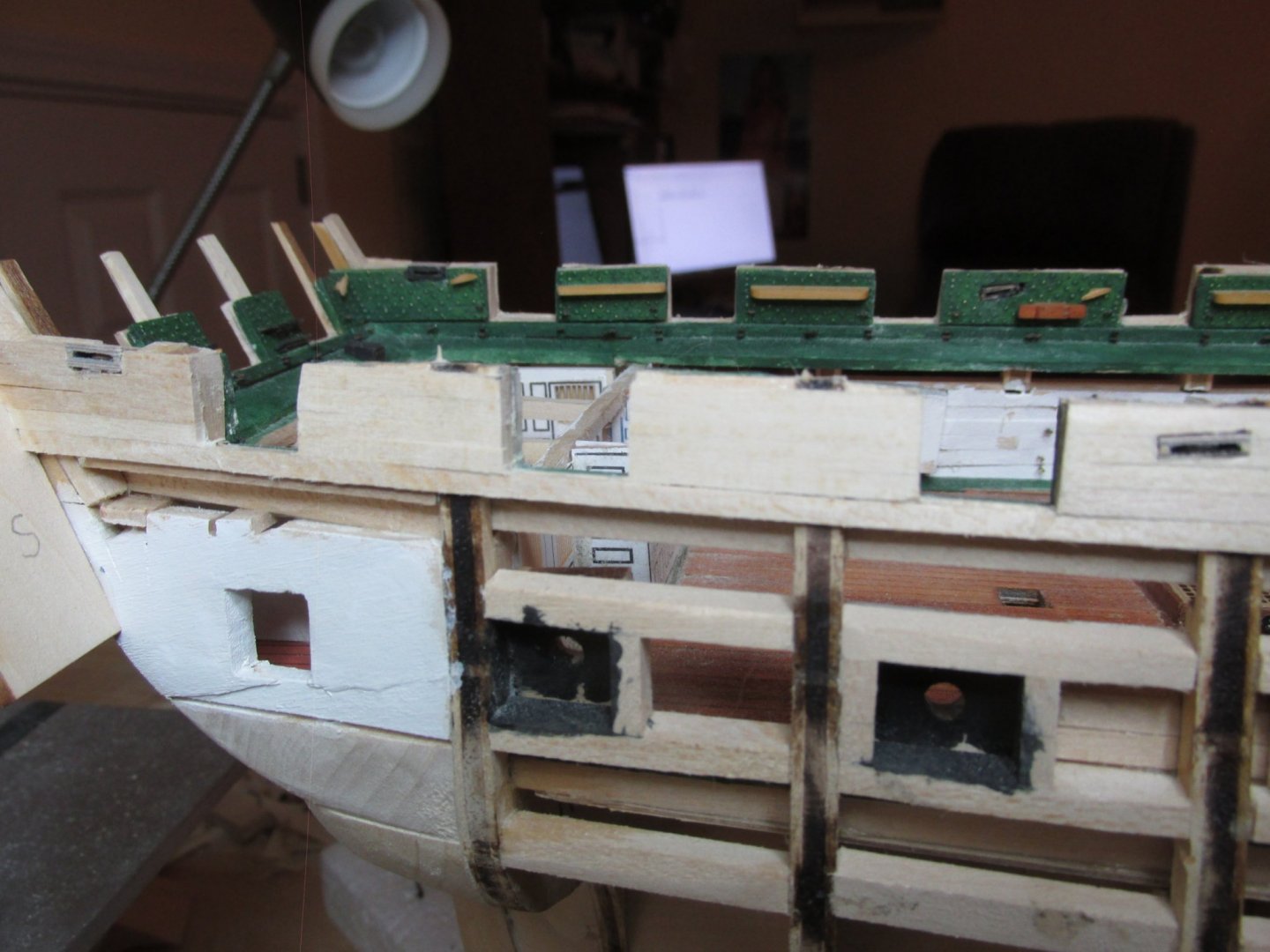
Finally, I got to work on the transom and the quarter gallery structures. Here, I am paying close attention to Robert Hunt’s practicum because the quarter galleries are a complicated construction. First the transom gun port area (spar and gun decks) were planked.
-
Any chance you have photos of your "wringer" set up? I'm still debating in my mind how I'll will do the nail impressions when I get to the copper stage.
- 55 replies
-
- 1
-
-
- constitution
- model shipways
- (and 1 more)
-
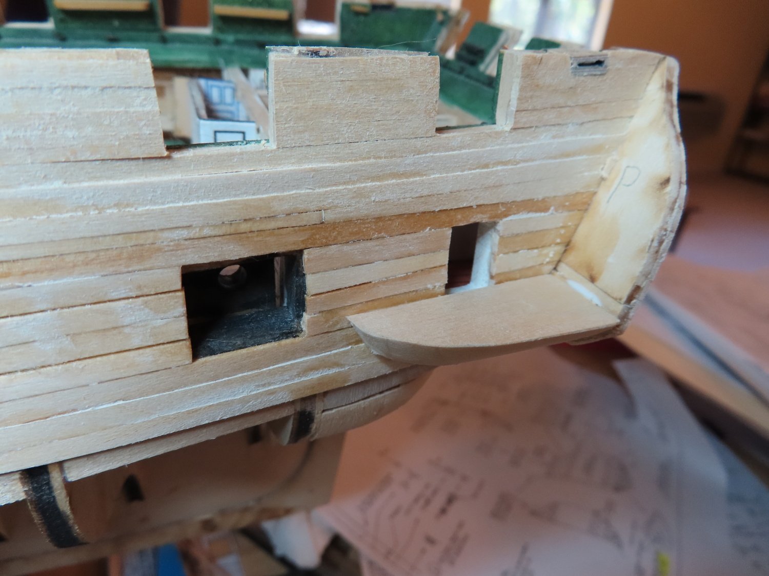
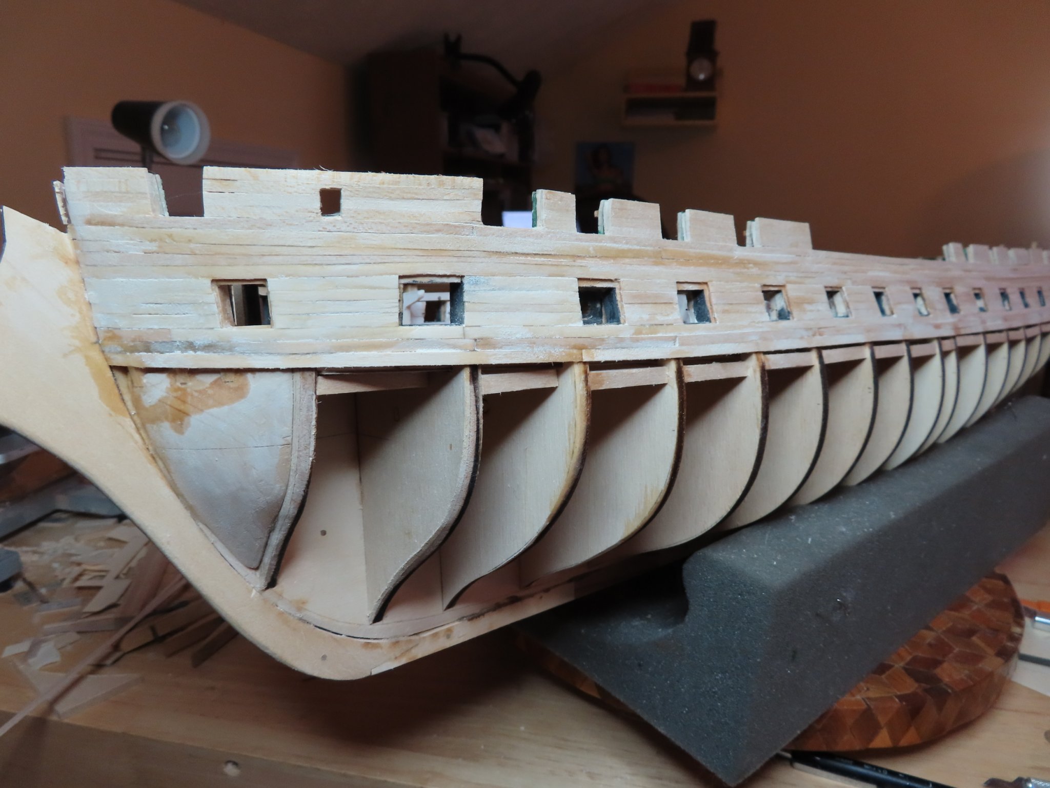
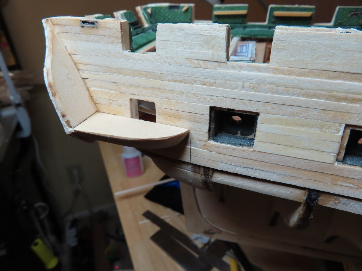
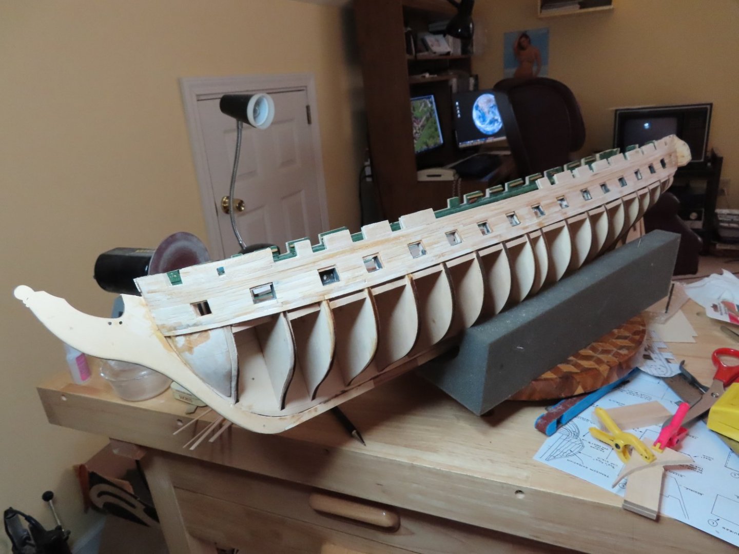
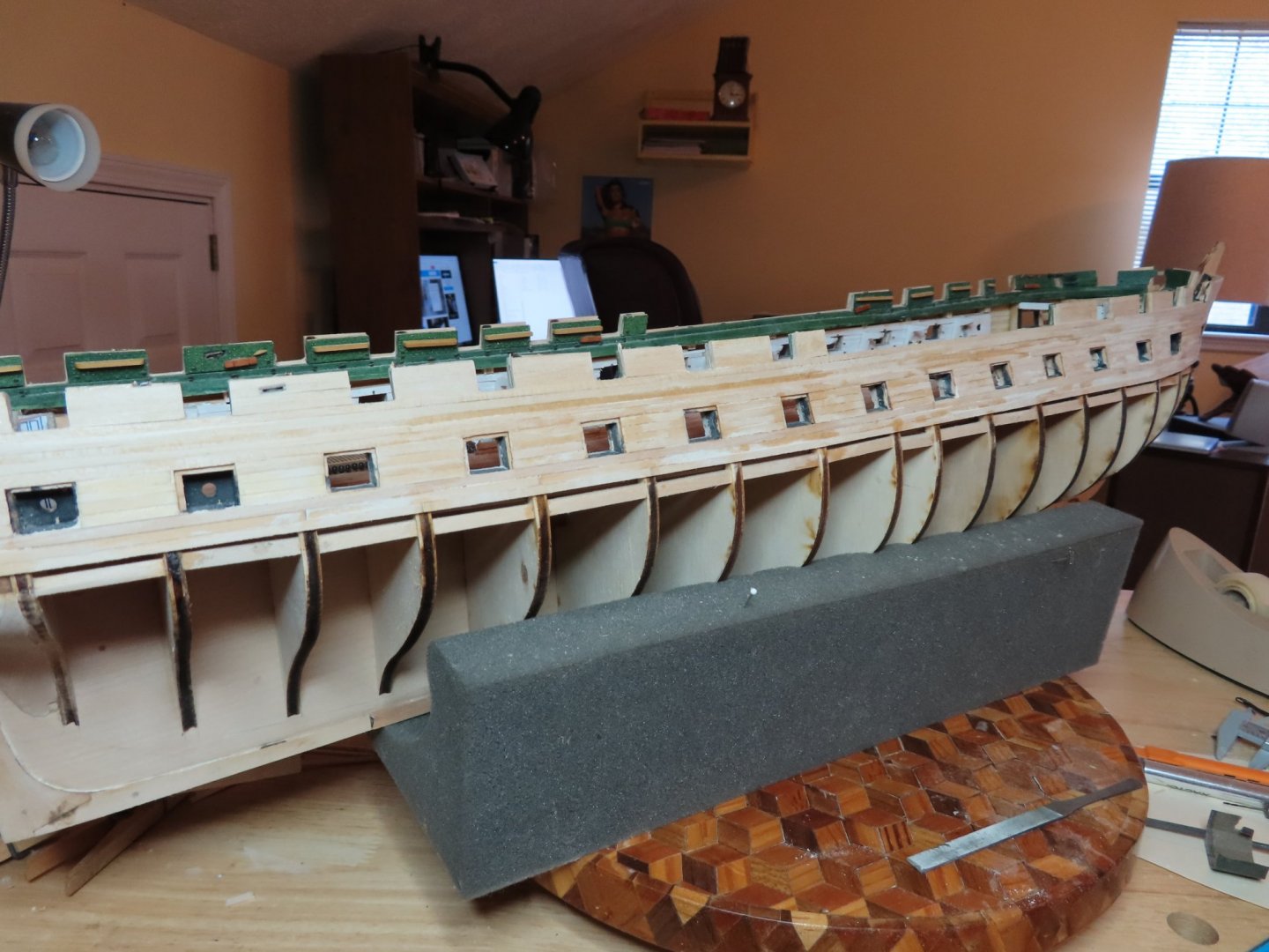
I finally finished the gun port planking plus three additional planks below the ports. The planking will work as it will be painted covering up all the “uglies.” If this were to be a natural wood finish, I would not be too happy. My only excuse (and not a good one) is that this is only the second hull I’ve ever planked.

-
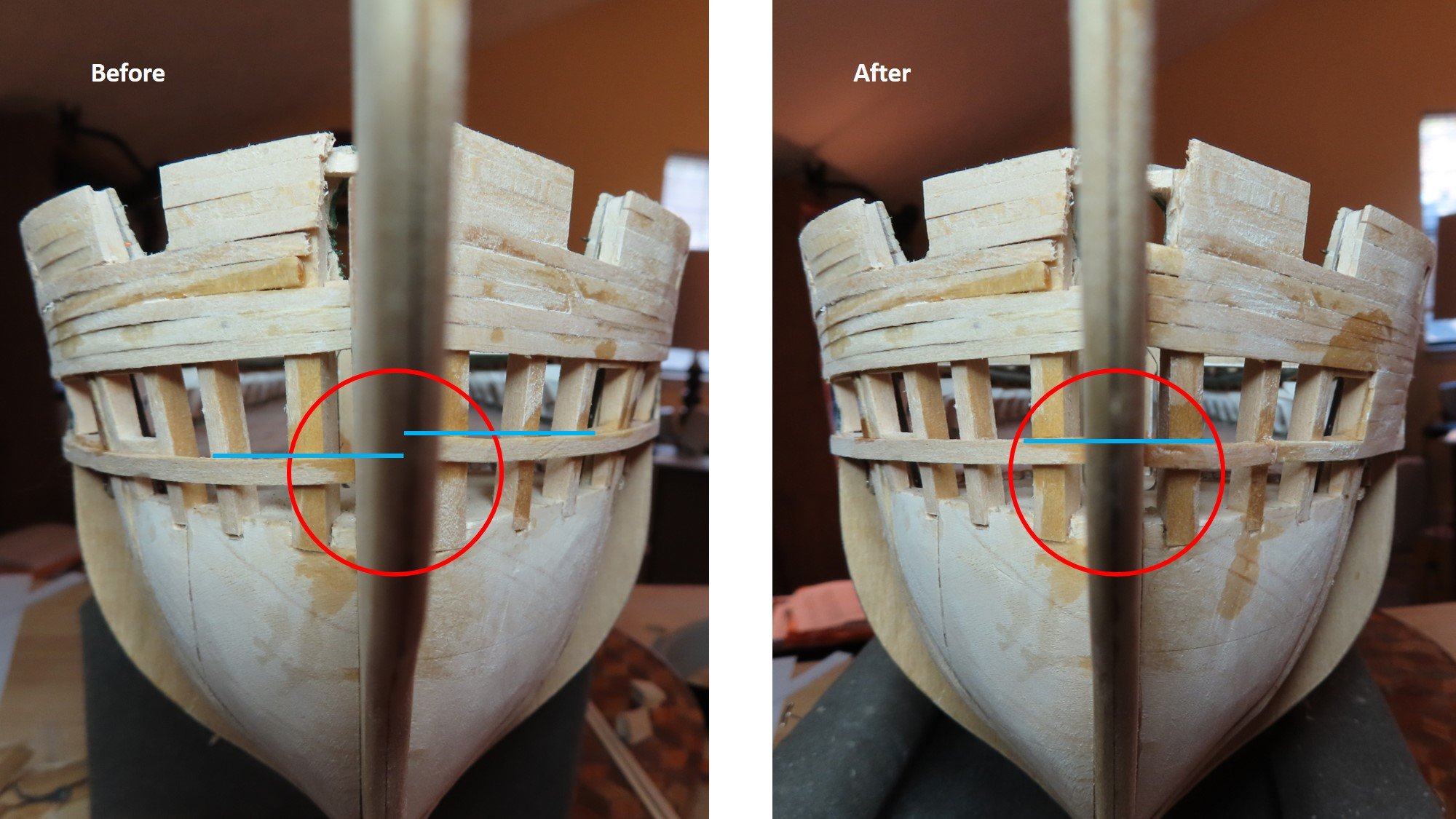
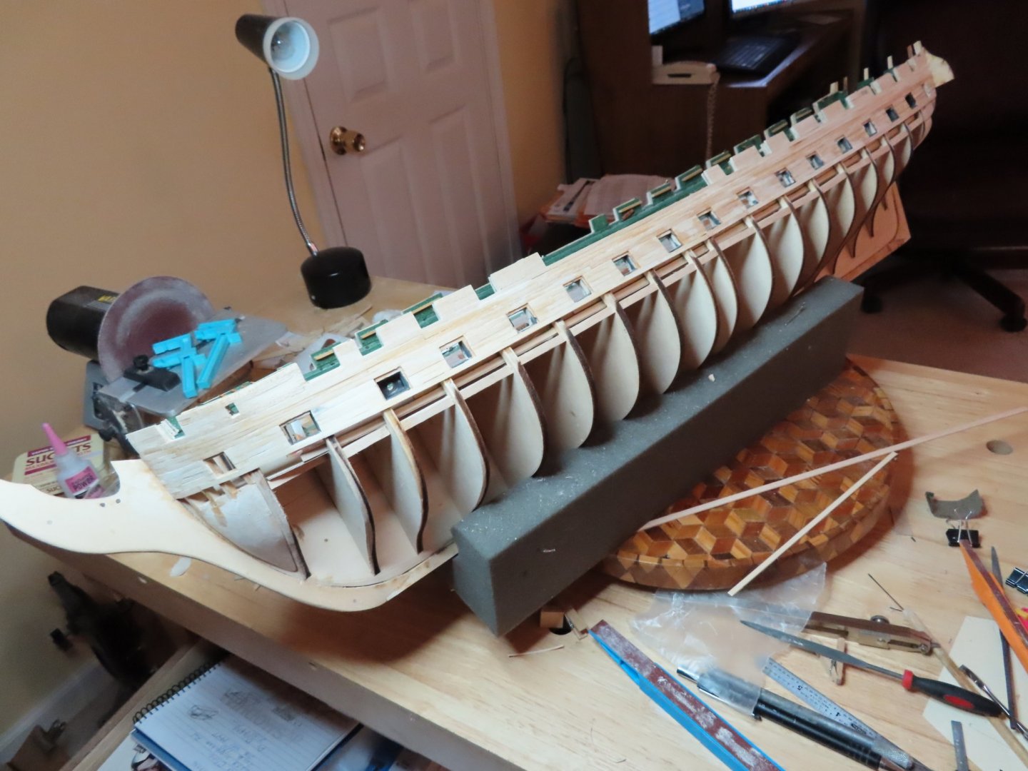
It’s been about a month and a half since my last post. Wow have things changed in the world around us. Everyone is warned about leaving the house. Luckily, we have an indoor hobby. I’ve been busy but not always with the model and as usual, I’m slow as molasses with the model building. Continuing on with the hull planking, I added the gun deck, gun port, sill planking on each side of the hull. As final check before I started to plank in between the gun ports, I noticed that I wasn’t careful enough with how I place those planks. Looking from the bow, one could see they didn’t line up. I had to carefully cut out a couple of inches worth of the sill plank on the port side and do it again.

-
Dan - She's been a favorite of mine too. I grew up in Newton MA, a suburb of Boston, and visited her on numerous occasions. I would like to to see build log of your efforts as I look at just about any blog I can find looking for that detail, technique, and problem solving that would help me me in my efforts.
-
Very nice. I hope mine looks as good as your when I finally get to this point. I'm using Robert Hunt's practicum as a guide (as well as following numerous other builders) and he substituted boxwood for the fife rails because the basswood laser cut pieces were so delicate, you were also guaranteed to break them. When I purchased my kit, Hobby Mill was still in operation and they offered a wood supplement kit based on Mr. Hunt's laser cut parts substitutions in his practicum. So, I bought it and as a result I've always planned on replacing the parts you discovered the hard way. Look forward to your next posting. Jon
-
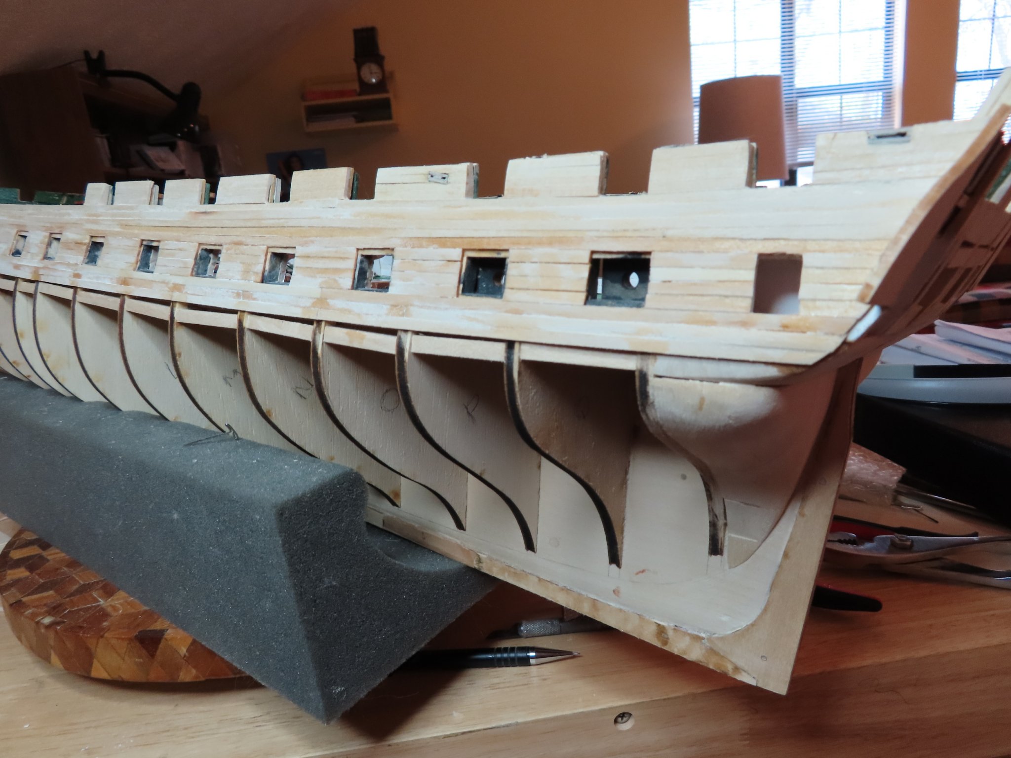
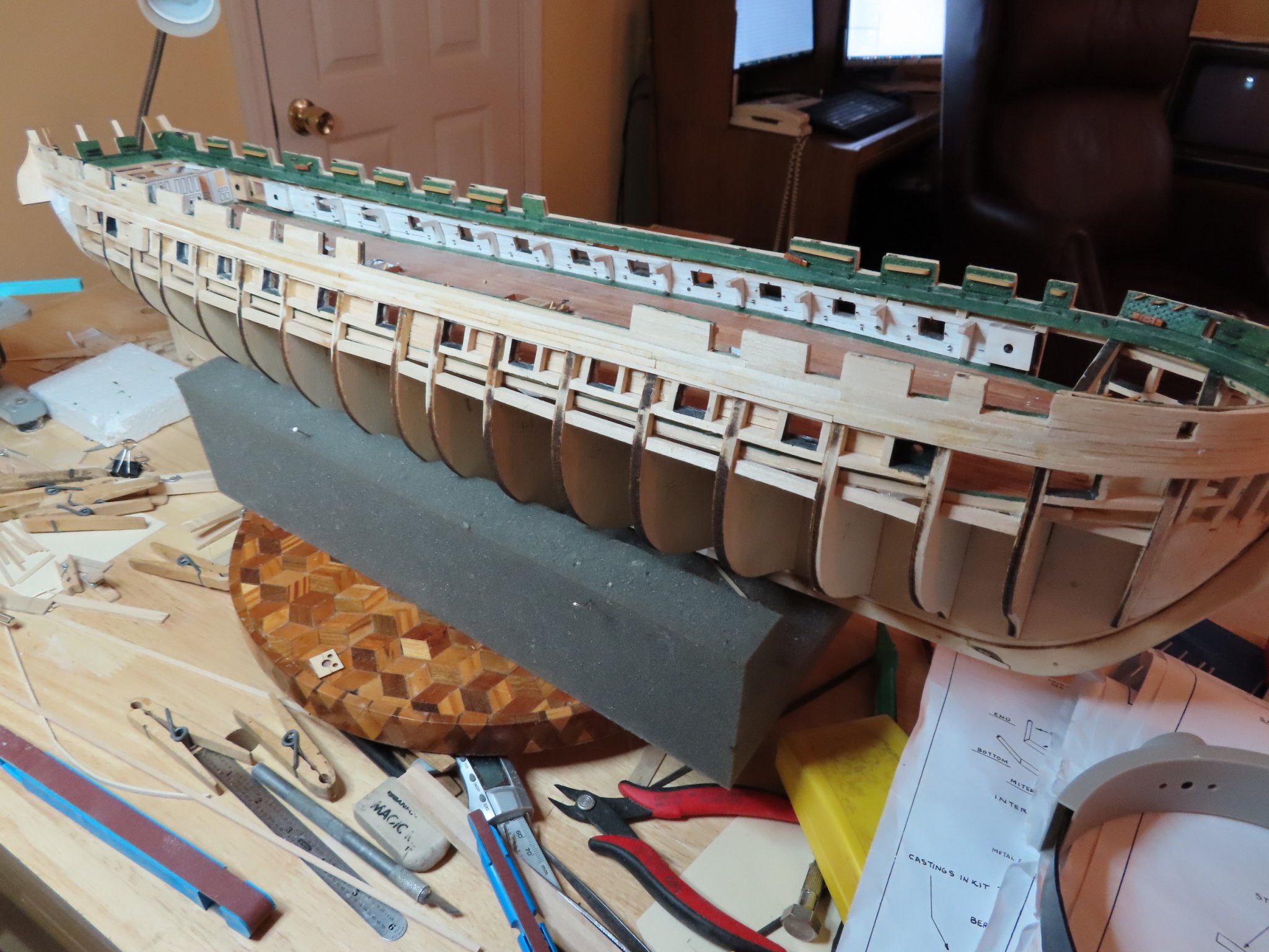
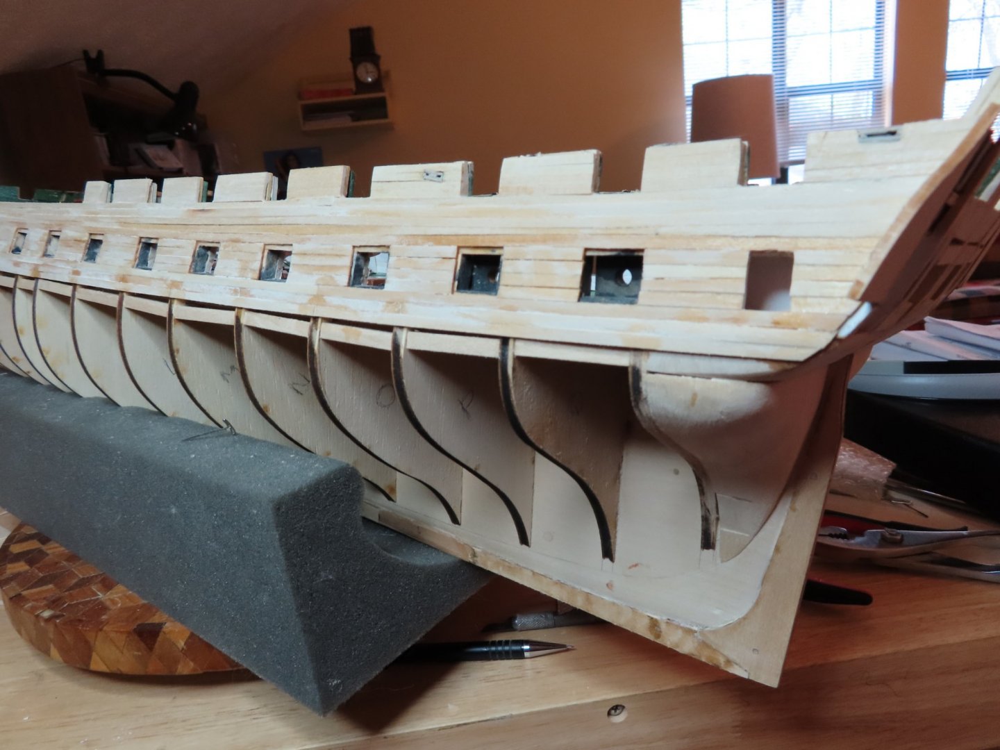
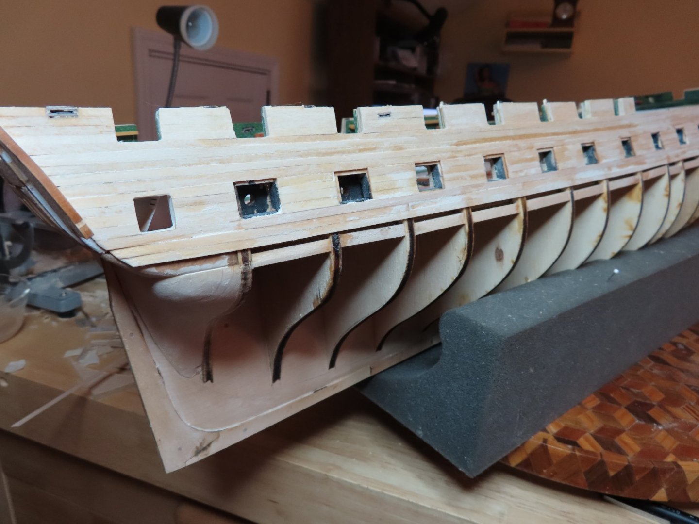
The first line of planking for the gun deck ports was started at the top of the ports with a line of planking resting on the jigs. Then three additional lines of planking were fitted above that so the were snug against the spar deck gun port planking. Next is planking in between the ports and just below them.

-
The build was put aside for a bit while I and my sister made a final trip to Florida to deal with the sale of my Mom’s condo and the disposition of her possessions. It was not something that I looked forward to, but it was done. We accomplished what was needed. After returning home and digesting the past events, I was ready to open the shipyard again. The next band of planking was the area of the gun deck ports. These are straight forward enough except that a 1/32” space must be provided around the gun port openings for the gun port lids. A simple jig was fashioned from the spacer block that was used to form the openings in the first place. A short piece was cut off and a second piece with the exact dimensions of the lid was made. The two were glued together so that when the jig was inserted into the gun port, it would create a void in the planking big enough for the lid to fit. It would also create a smooth border. Two were made.

-
You could offer to pay for the postage if they would send the parts. They are very reasonable. BYW, you are moving at a very reasonable clip, much faster than me, and I'm retired and a bachelor. There is always other parts to work on while you wait for the mail delivery.
-
It's been a while since I checked up on you. You do work under some adverse conditions. You might have saved some extra work/grief if you had contacted Model Expo. They have a no questions asked parts replacement policy. I'm sure they would replace any of the pre-cut wood you lost for what ever reason. What I don't know is their over seas postage policy. Jon
-
Thanks Kmart and Bob. That was just what I needed to know Jon
-
When I was contemplating how I would simulate the bolt heads, I did consider the "glue" method. But because I didn't have access to syringes (don't know if you can just walk into a drug store and just buy them or if you need a prescription) and I figured you would need a bunch of them as the glue eventually clogs them up, or a method to consistently create uniform thousands of drops, I chose not to do it that way. Also, I could adjust the position after placing them on the wood with Wipe-on Poly (before it dried). Your build looks great and you are moving a whole lot faster than me. Jon
-
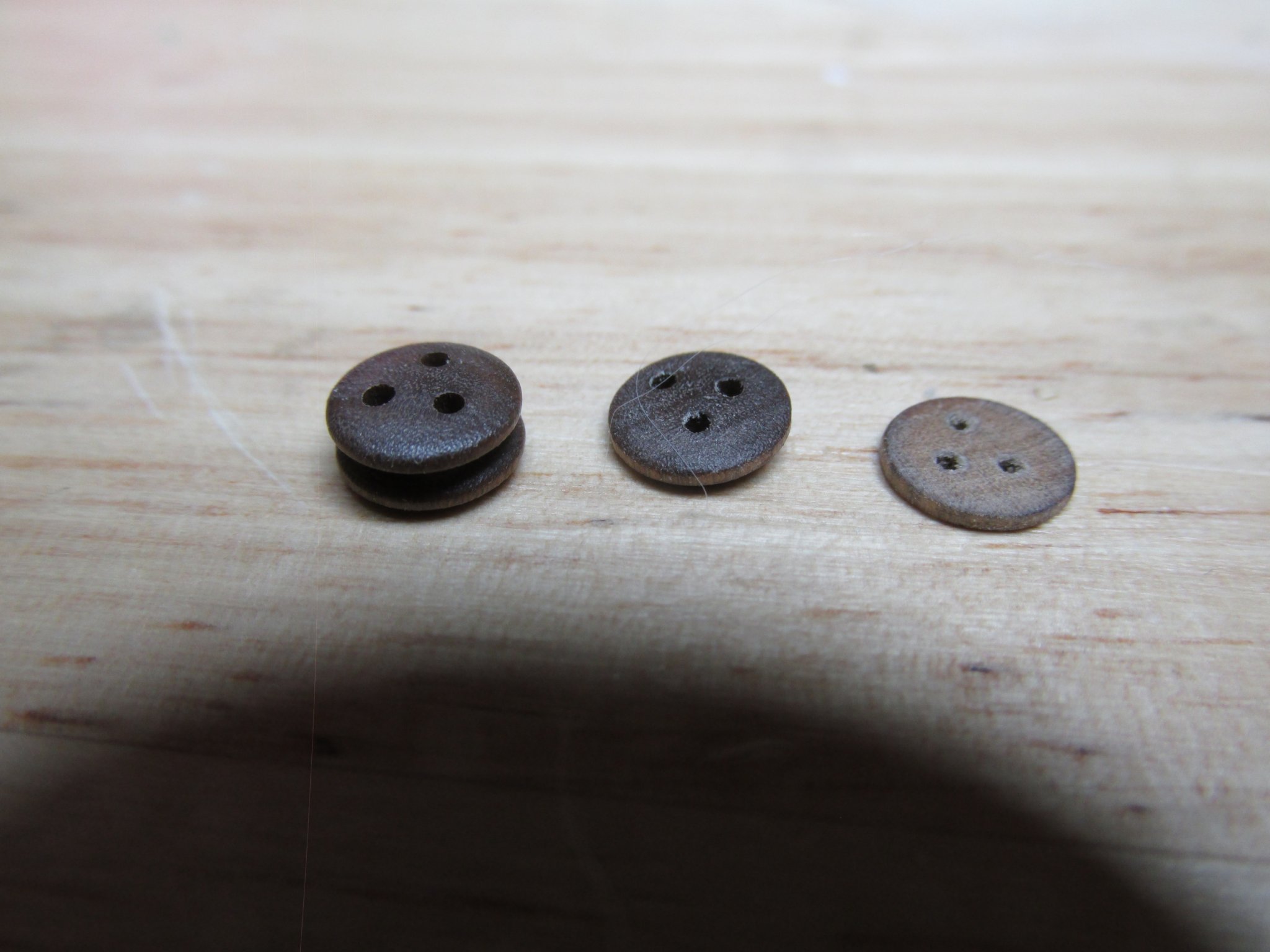
You are right that a lot of modelers have gotten the representation of the fasteners of the copper plates wrong. They look like boiler plate rivets sticking out off the plates. As you can see from the image below, the plates are attached with copper nails which results in fine dimples on the plates. I am going to attempt to simulate the effect on my build using a stamp with fine needle points embedded in it. I managed to simulate the bolt heads on the bulwarks somewhat successfully (using 0.6 mm rivets I made using a fine punch) although I still feel the scale is off.

- 55 replies
-
- 4
-
-
- constitution
- model shipways
- (and 1 more)
-
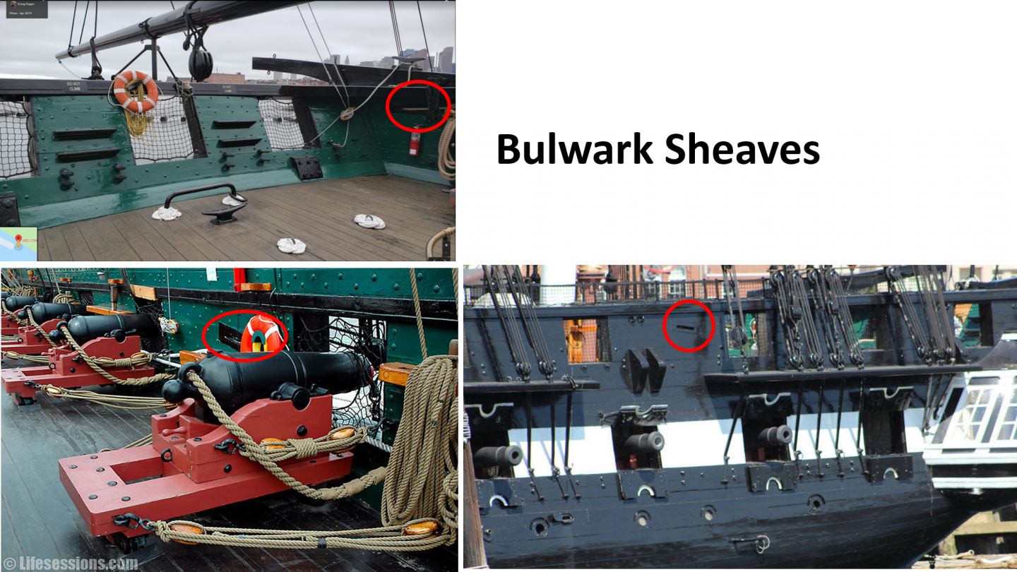
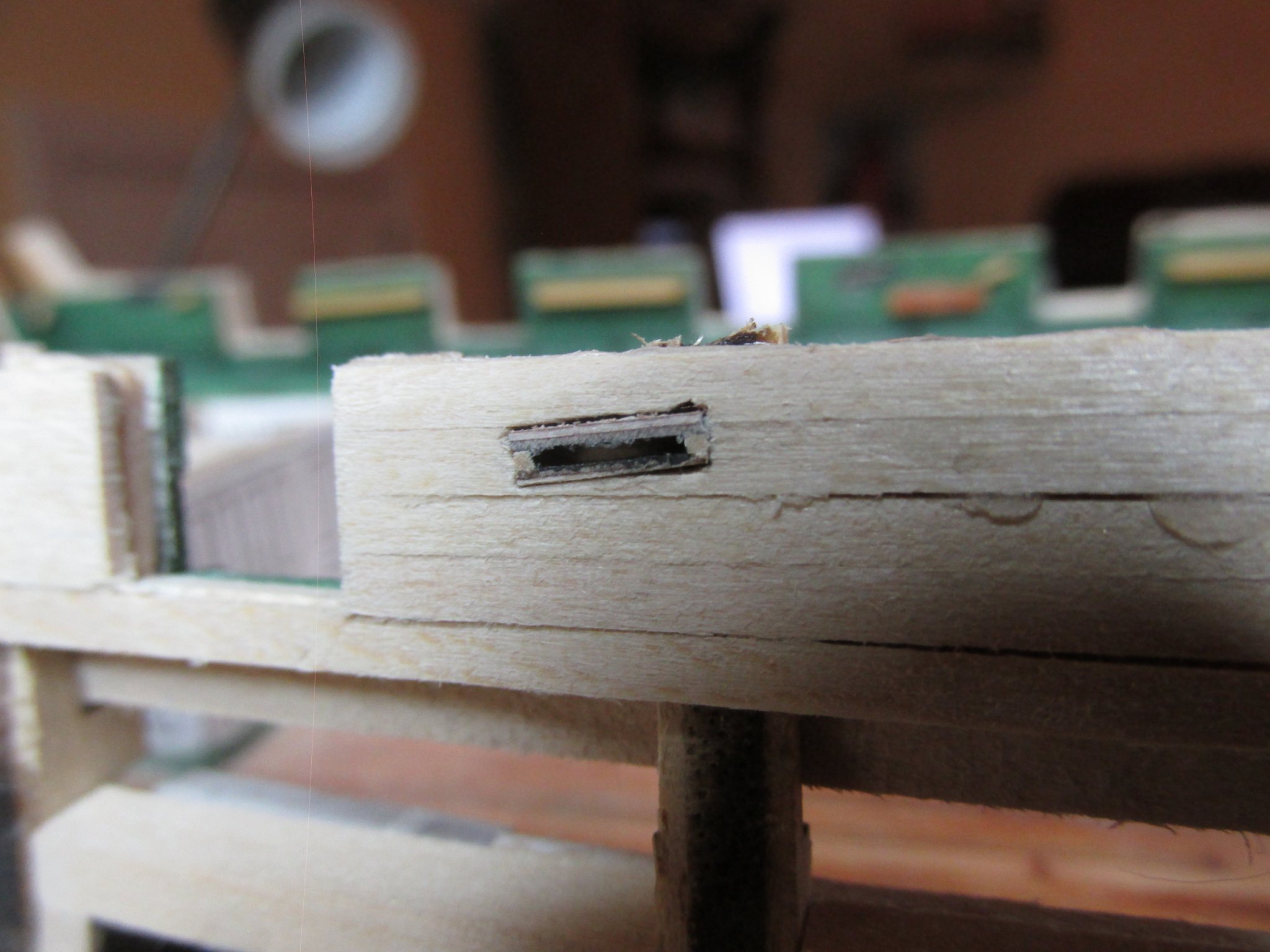
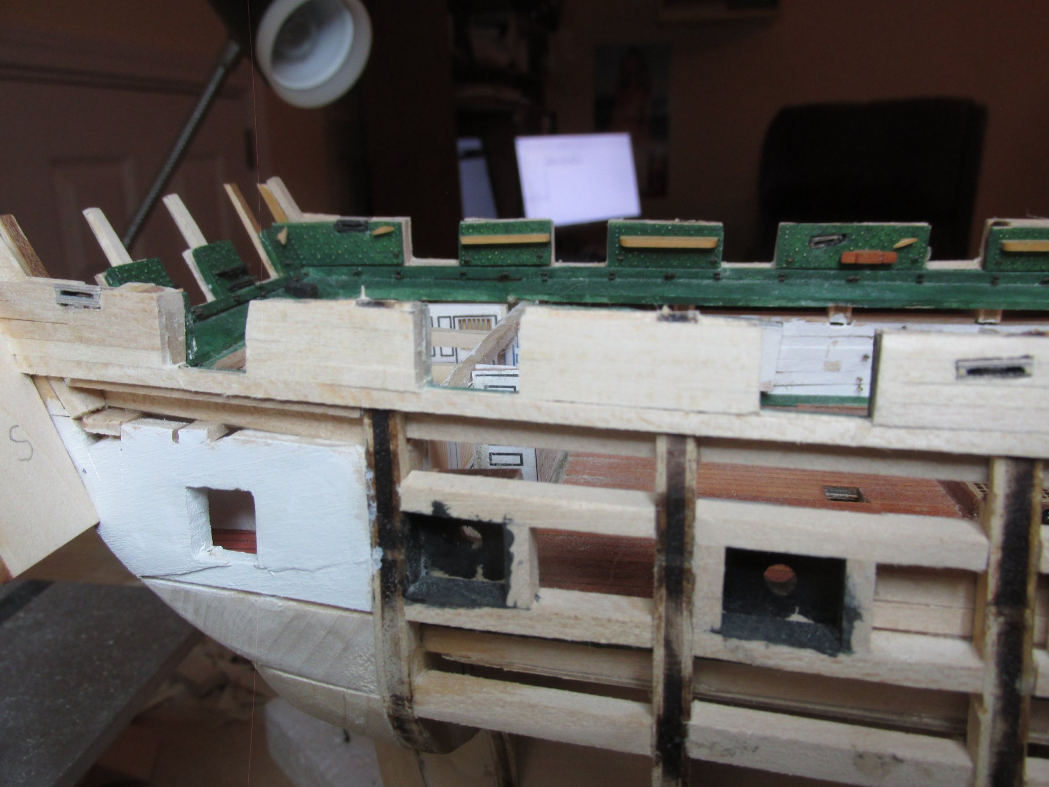
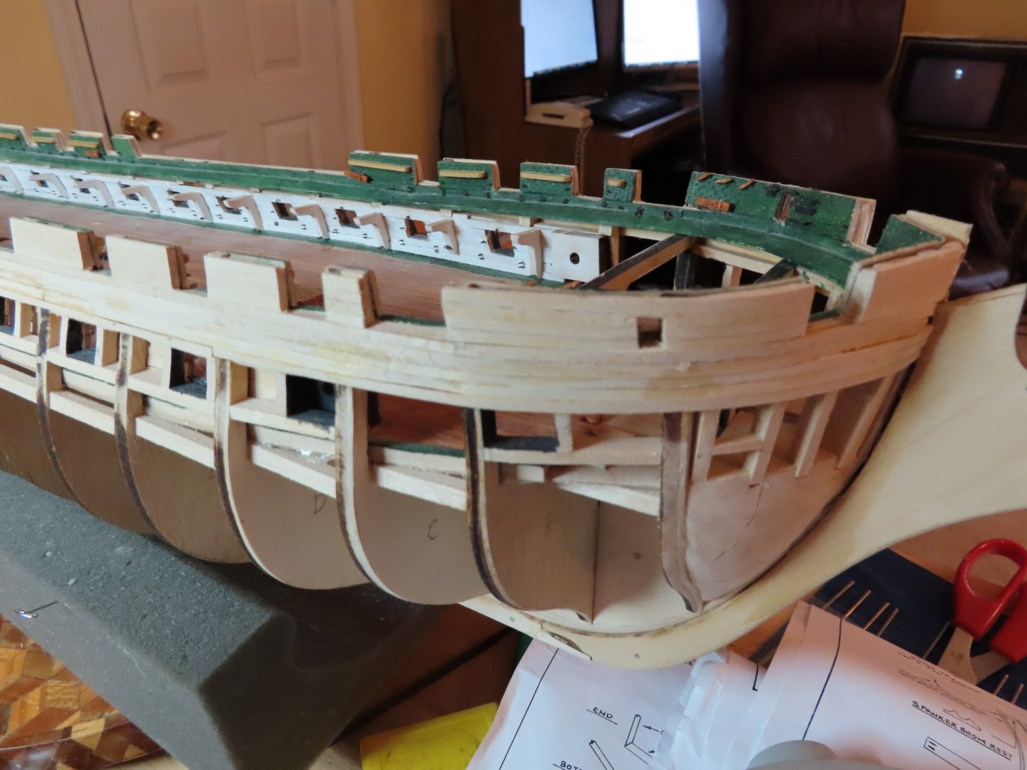
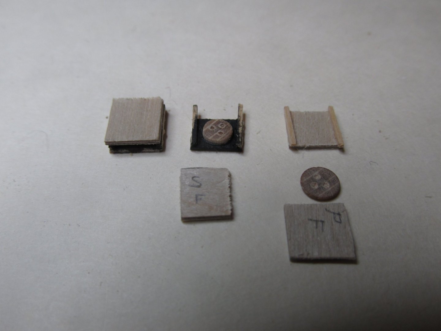
After detail filing each sheave and hull sheave openings so the sheaves would easily slide into place, they were glued in flush to the interior bulwark wall. On the hull side, they were filed flush.

-
I had read on someone’s blog (I’m sorry I forgot where) about different uses for miscellaneous deadeyes. I had been given a bunch of odd fittings including some deadeyes from a model train hobbyist friend of mine who had no use for them, so I tried to see if I could use a couple. Using two 5mm Mantua deadeyes, I sliced them into halves and sanded both sides of each of the four slices till they were 1/32” thick. Then using 1/32” plywood, two rectangular pieces were cut for each of the four deadeye slices. These were to become a sandwich 3/32” thick. The plywood was used because it was convenient and only the edges would be visible, and these would be painted. Two pieces of 1/32” x 1/32” stock were used for the sides of each sheave completed the housing. The housing interior and the edge facing the deck were painted black, and the parts glued together. There was no effort made for the pulleys to rotate because they didn’t need to.

-
Continuing with the spar deck bulwarks, it was time to install the four bulwark sheaves at the aft end of the model.