JSGerson
-
Posts
2,652 -
Joined
-
Last visited
Content Type
Profiles
Forums
Gallery
Events
Everything posted by JSGerson
-
 Me too.
 -
Within an hour of my last posting things changed. It had been almost a year since my left eye cataract surgery. I had seen the eye doctor for a scheduled appointment the previous week for the right and told him that I was feeling occasional pain. He said it was time we did the right since the right cataract had gotten bigger and was swelling the lens. The following week I got the required EKG and Covid-19 test. BTY, the Covid-19 test is the longest 15 seconds you will ever endure – painful. OK that brings it up to my last post. I get a pain like someone pokes me in the eye which lasts from Saturday evening to Monday morning and my right vision is completely fogged over. My left vision still hasn’t fully recovered. I still can’t read with it The original planned 20-minute surgery took an hour and a half which the doctor described as the most difficult surgery he had performed in his 35-year career. So right now, my right eye is still fogged up with four stitches and my left eye has no close-up vision. Corrective lens are about two months away, awaiting stitches removal and healing. Model building will have to wait some more. Typing this message was a pain even with the zoom in and spell check capabilities of a word processor. I keep hitting the wrong keys.
-
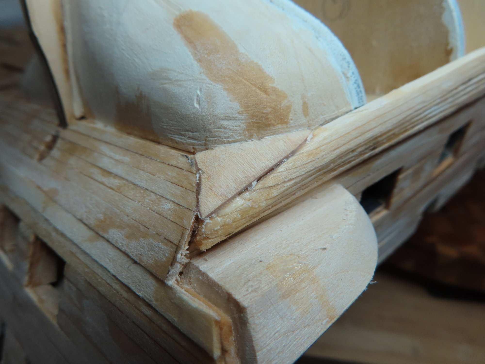
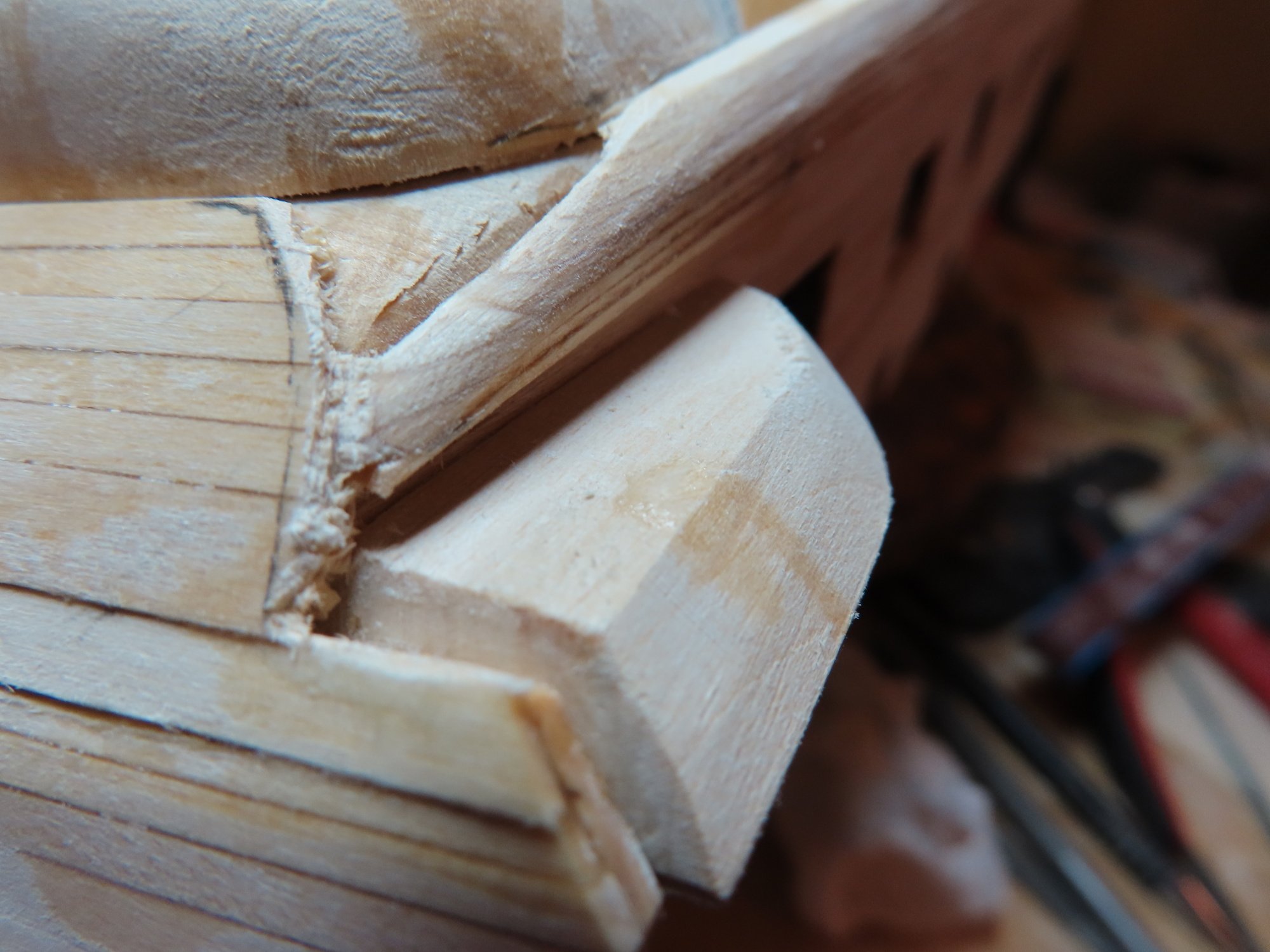
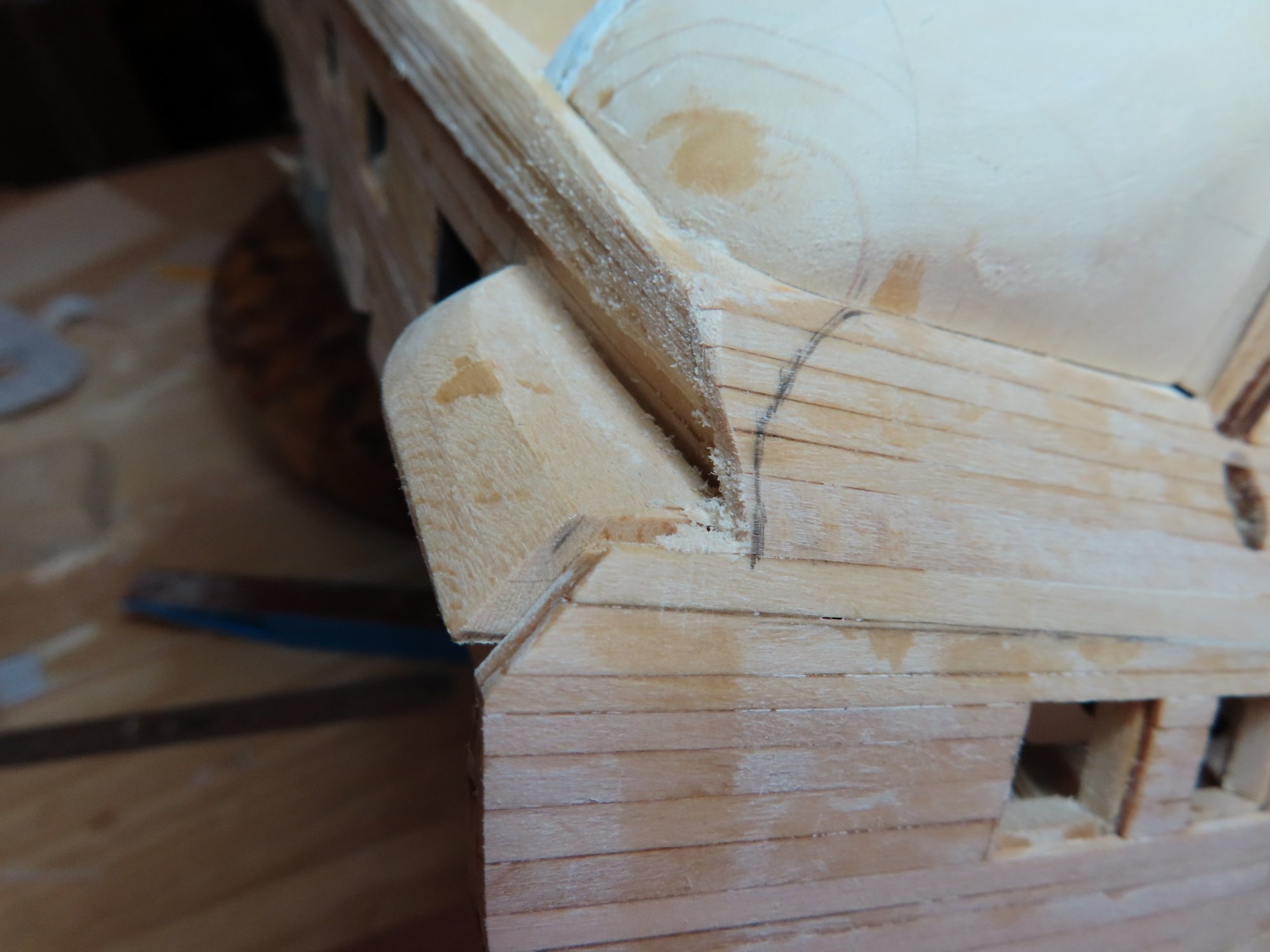
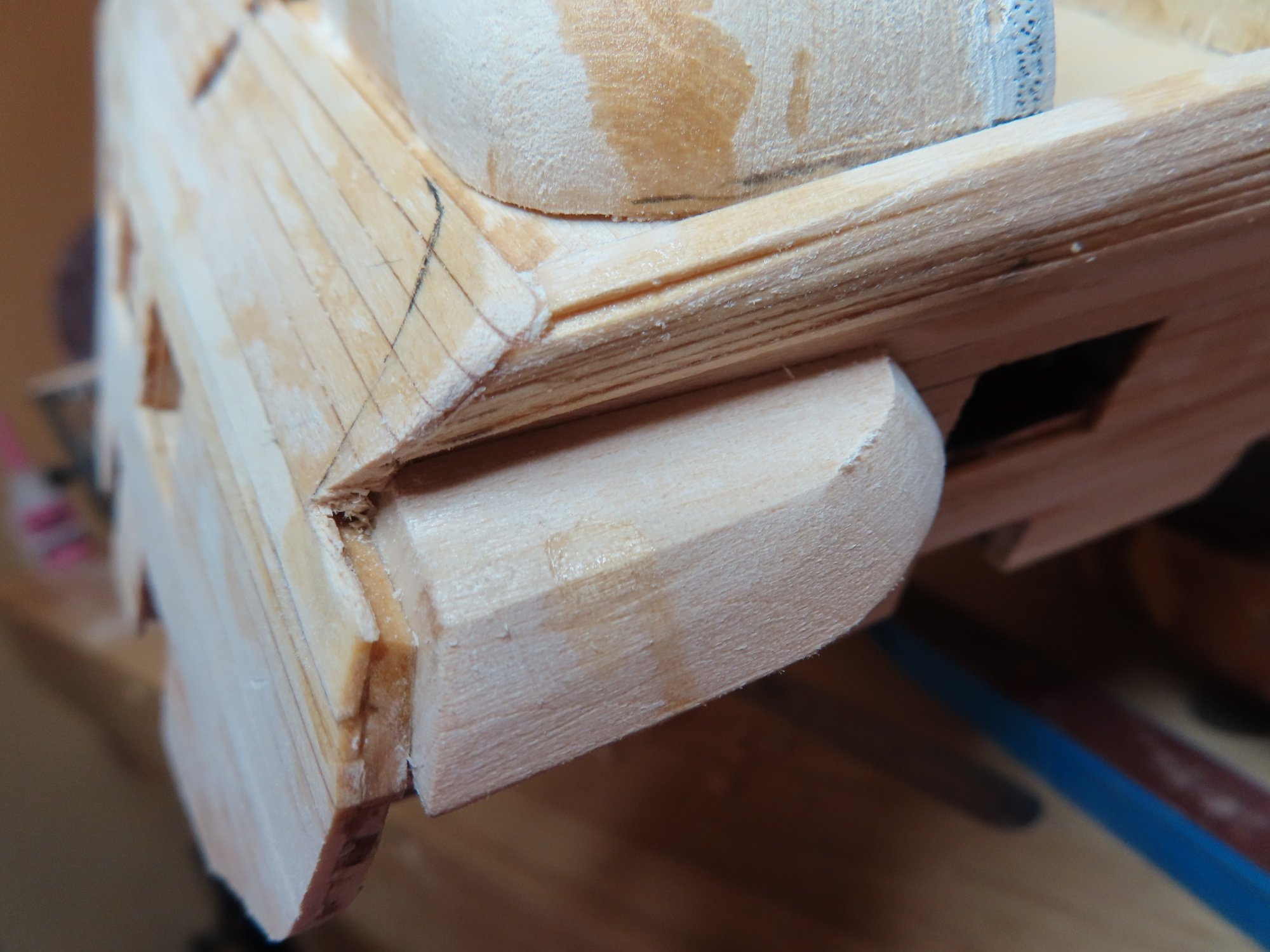
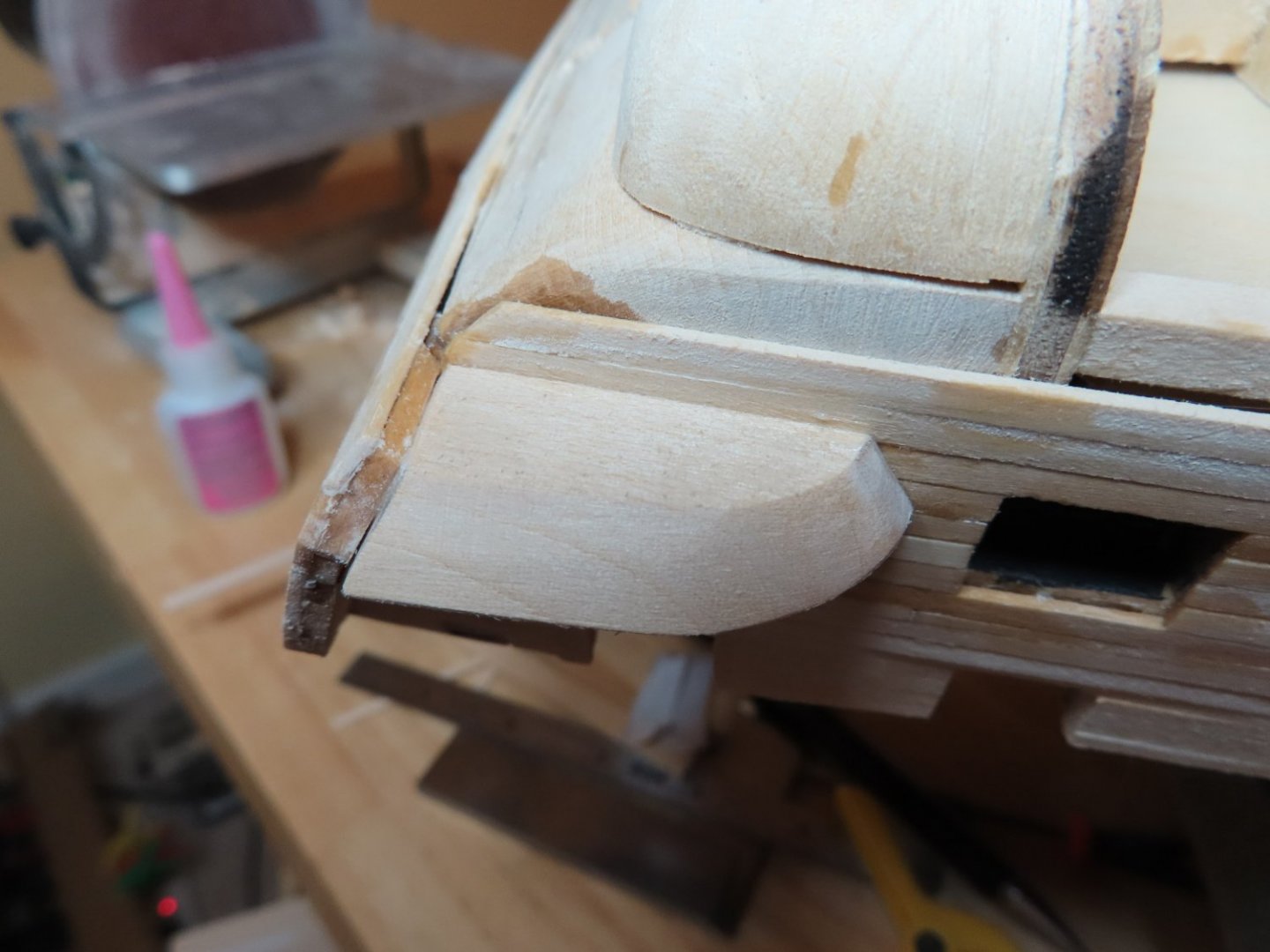
I don’t feel too bad as Mr. Hunt stated in his practicum that he had to use a bunch of wood filler as well. Once I finish the basic structure of the quarter galleries, I will fill in any remaining gaps with wood filler.

-
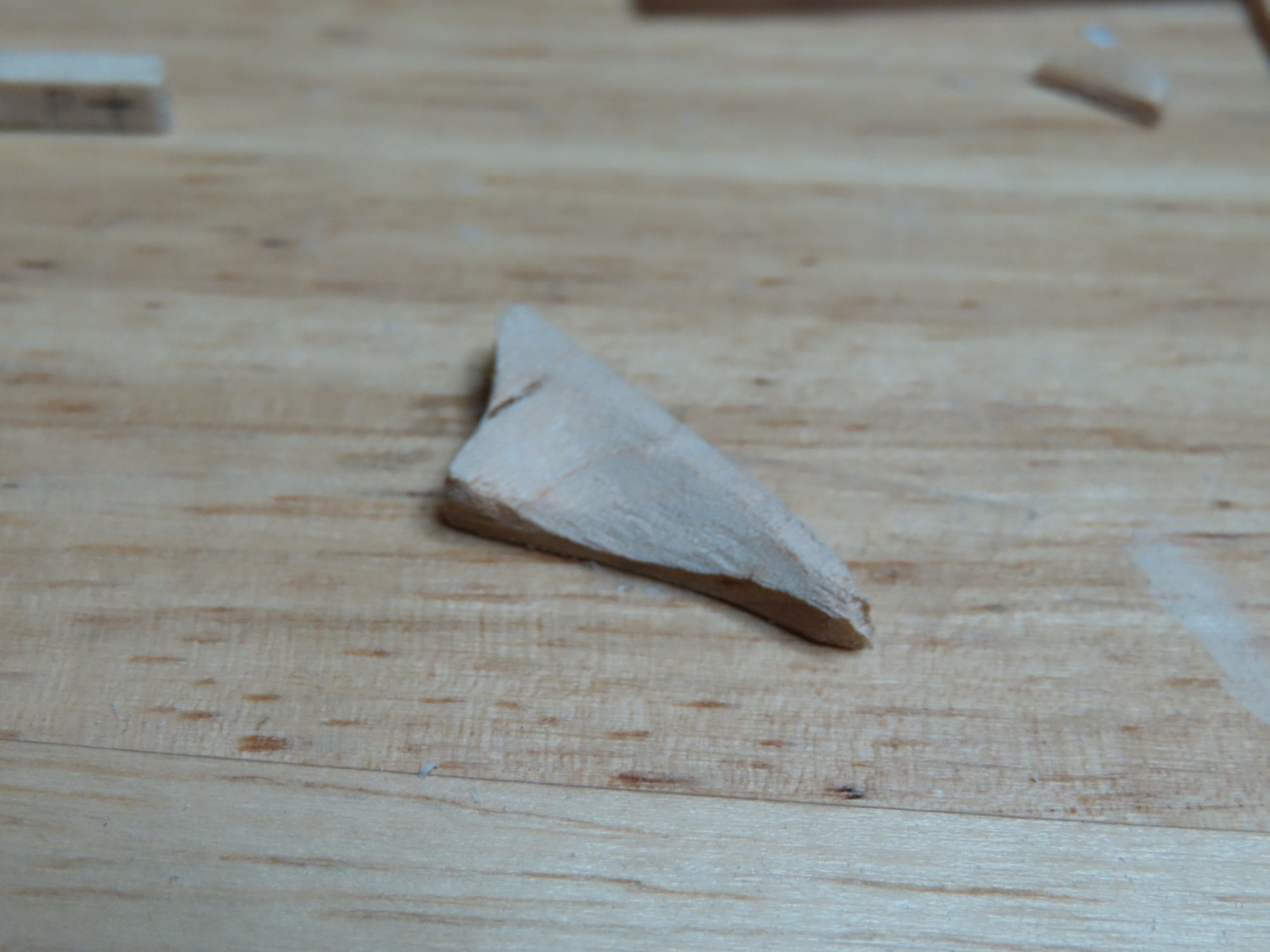
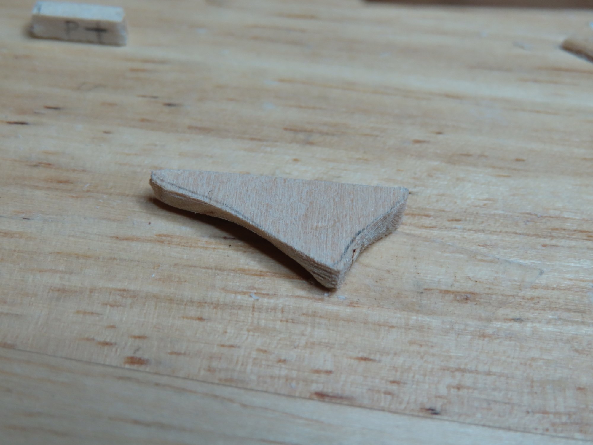
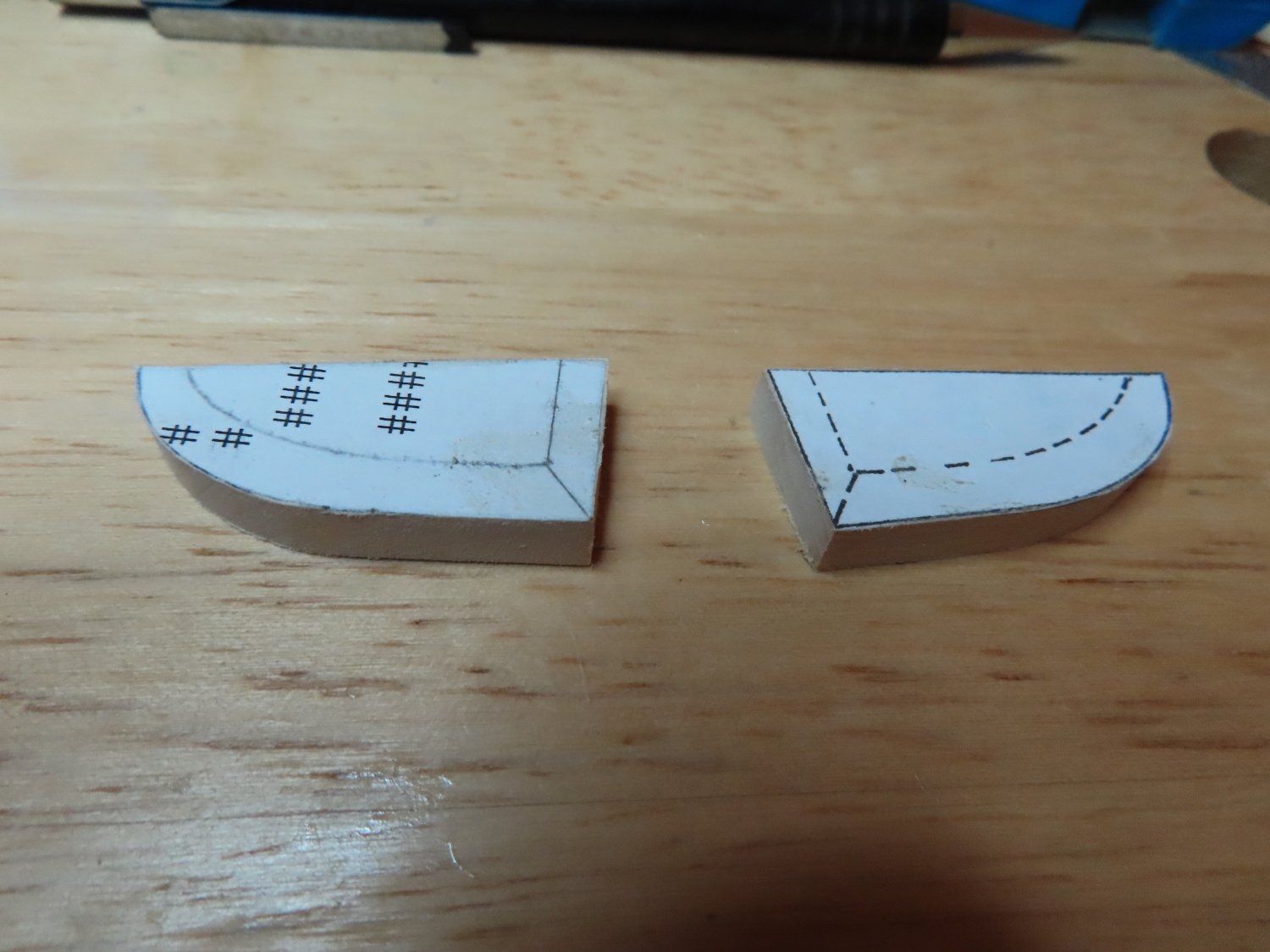
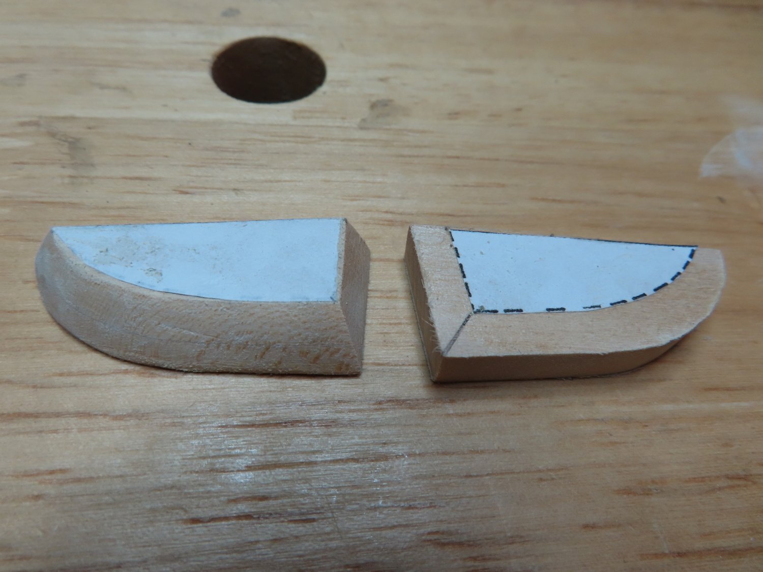
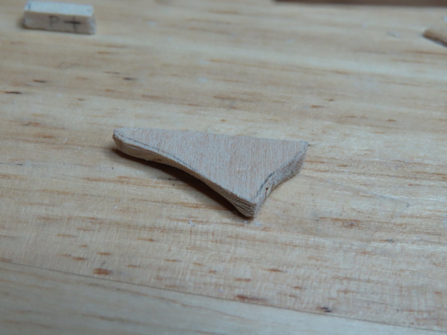
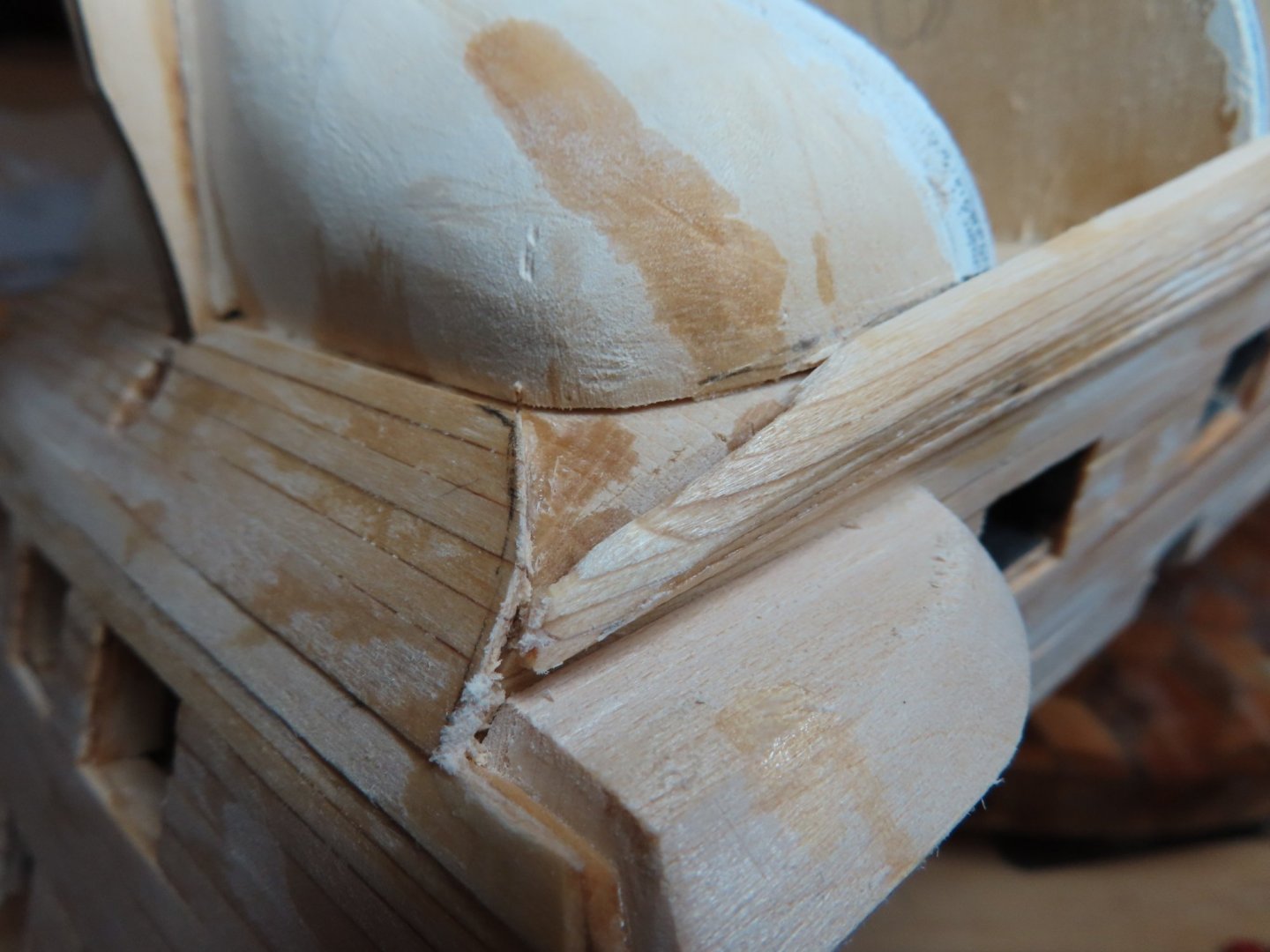
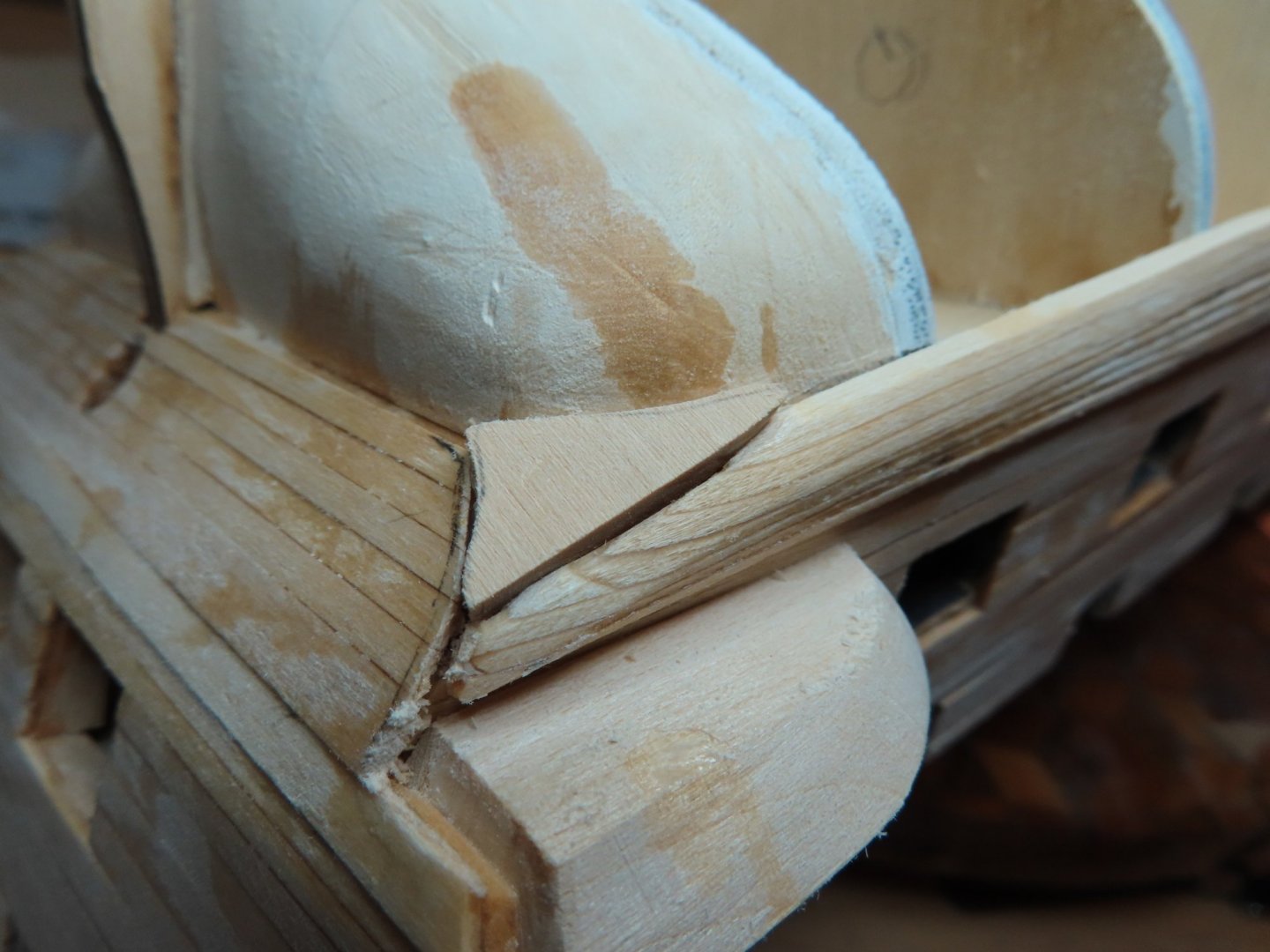
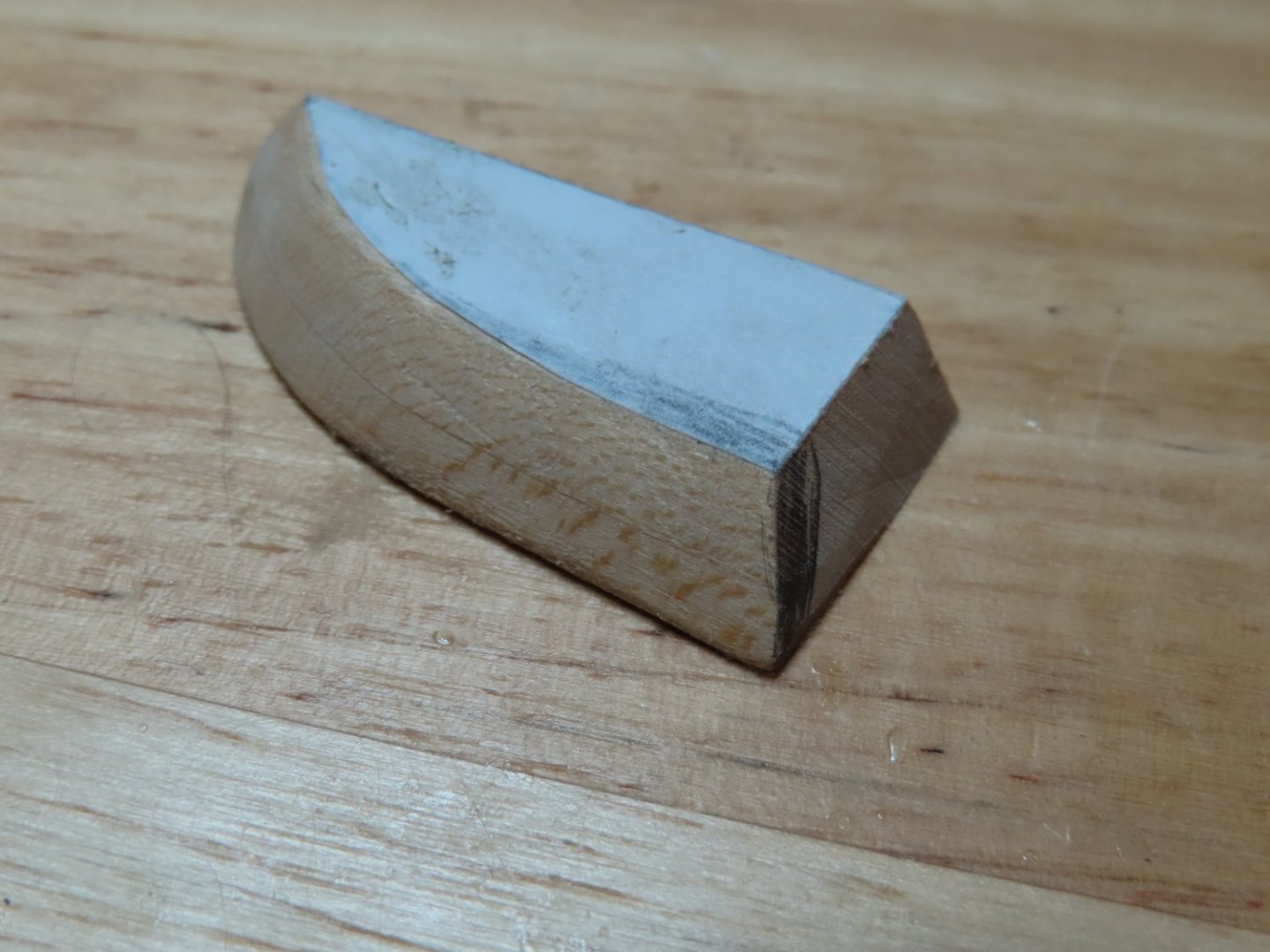
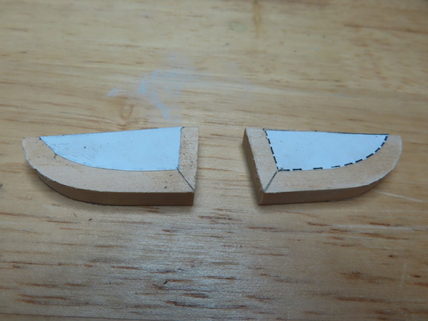
The patches were made by taking a piece of scrap basswood and cutting it into the basic triangle shapes to match the areas of repair. The through repeated trial and error, I carved the necessary contours on the bottom of the patch so they would snug. The patches were then glued into position and then filed to their final shape.


-
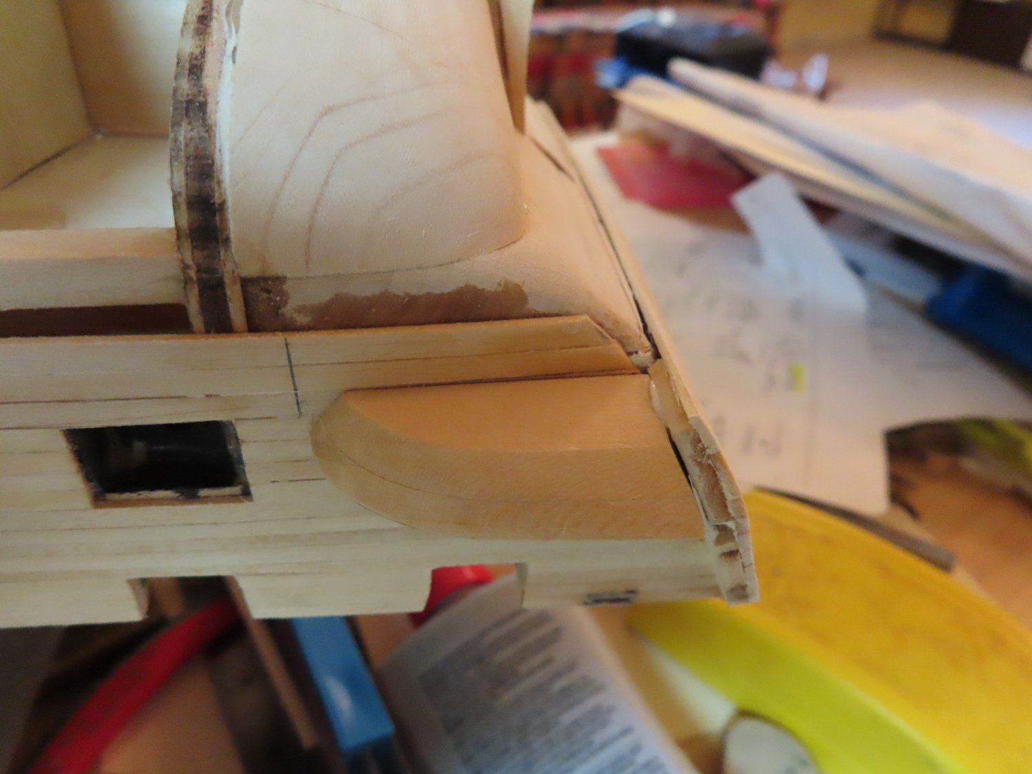
Luckily, this area of the model probably will not be seen very well by the casual observer. Following my sketch line, I continued to trim the transom and filed down the corner of the wale. Instead of ripping out chunks of the wale to make the repair (and probably my hair as well), I opted for a wooden filler patch. The whole thing will eventually be painted black and will be on the underside of the model in the shadows so hopefully it won’t attract any attention.

-
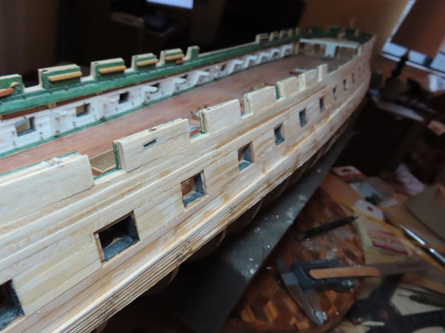
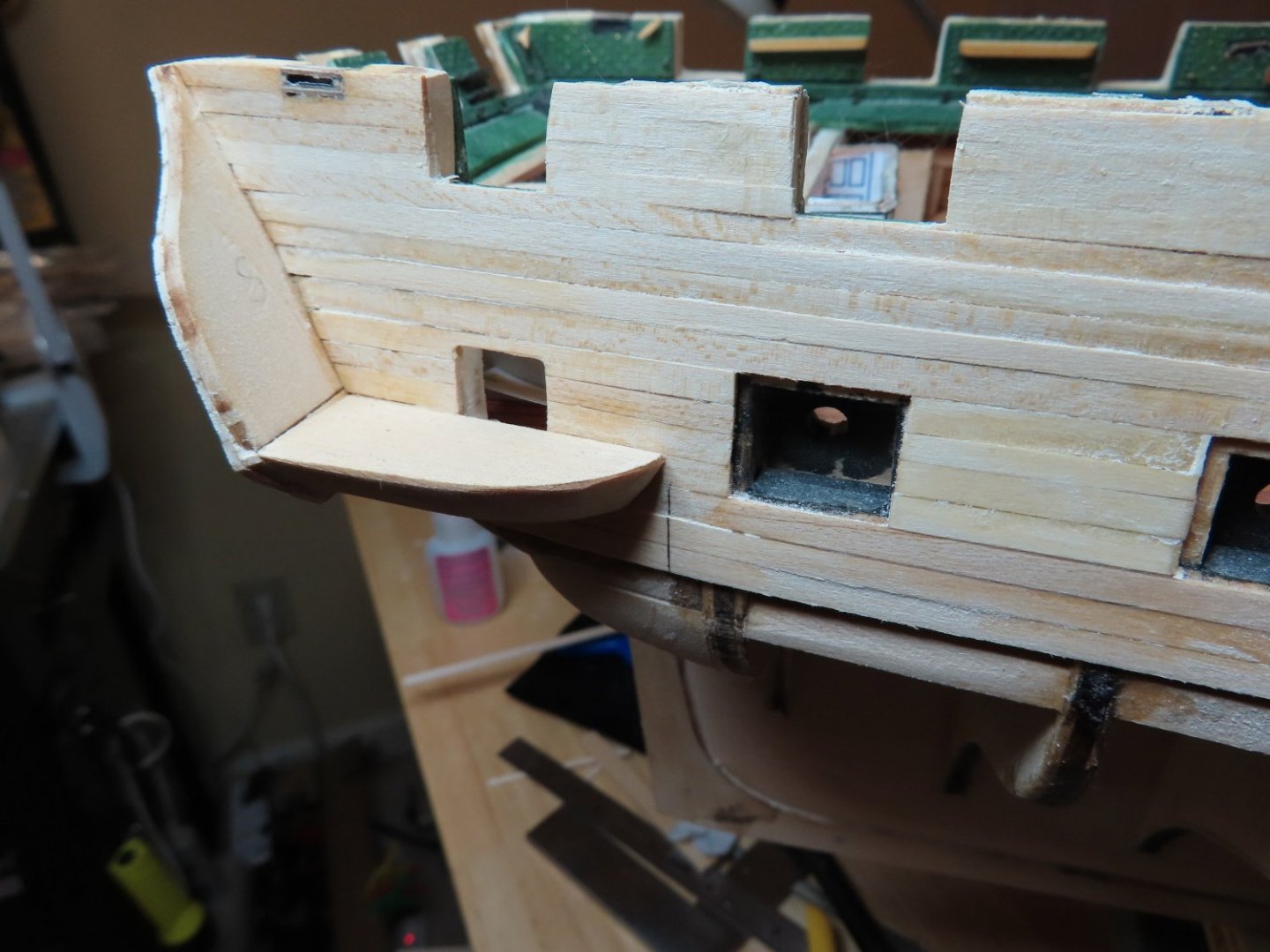
The wales were tapered with a sanding stick and lots of elbow grease, so it took a while. Now came the part I was not too sure of. As I mentioned earlier. I did not trim the lower transom because I was quite unsure where or what the cut was supposed to line up with. Well I found out. It was only after I trimmed the excess transom planking that I realized that the wale was supposed to bend around the stern and mate up with the transom. Mine didn’t. Had I trimmed the transom first, as instructed by the practicum, I might have realized what should have been done.


-
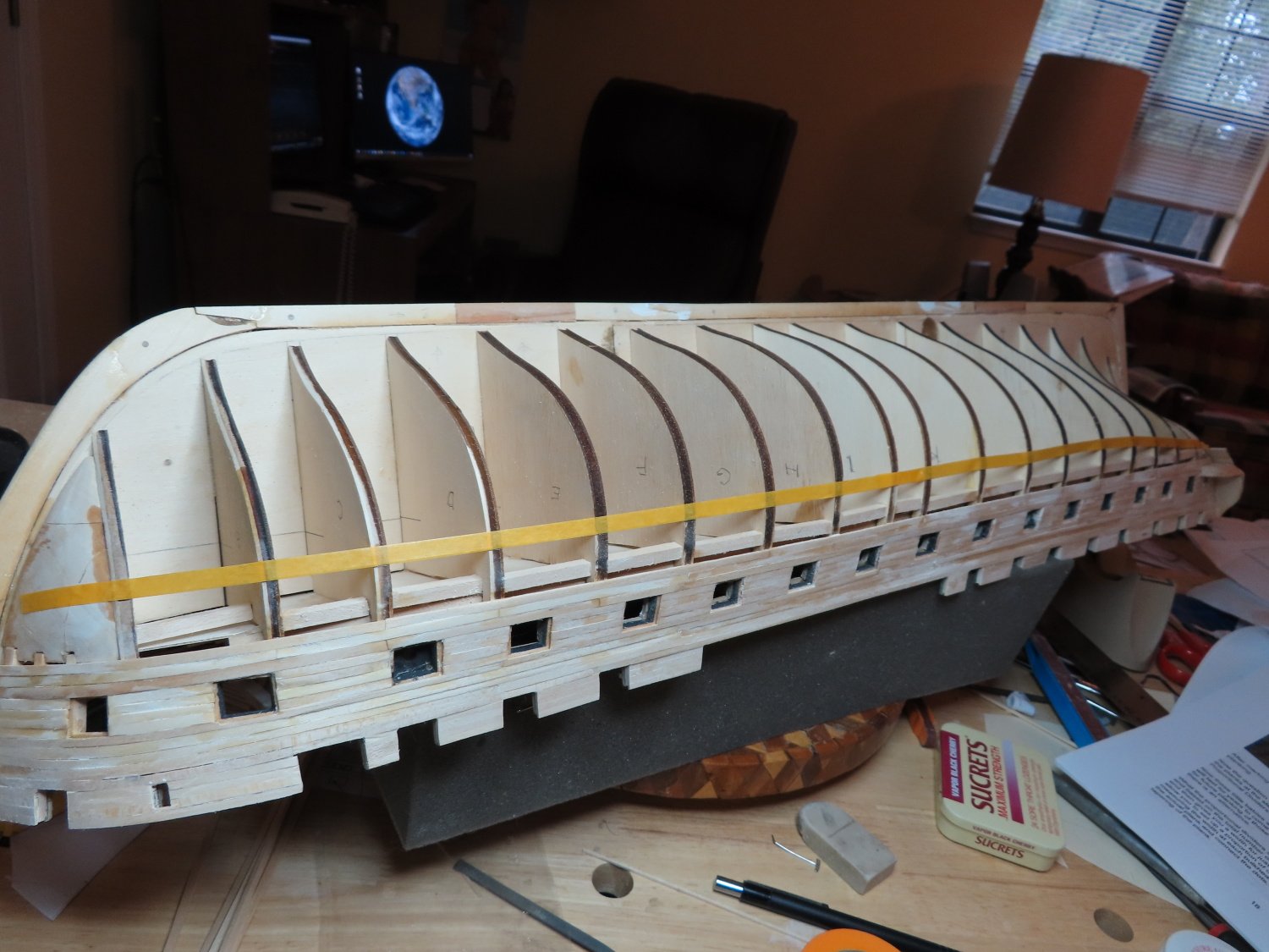
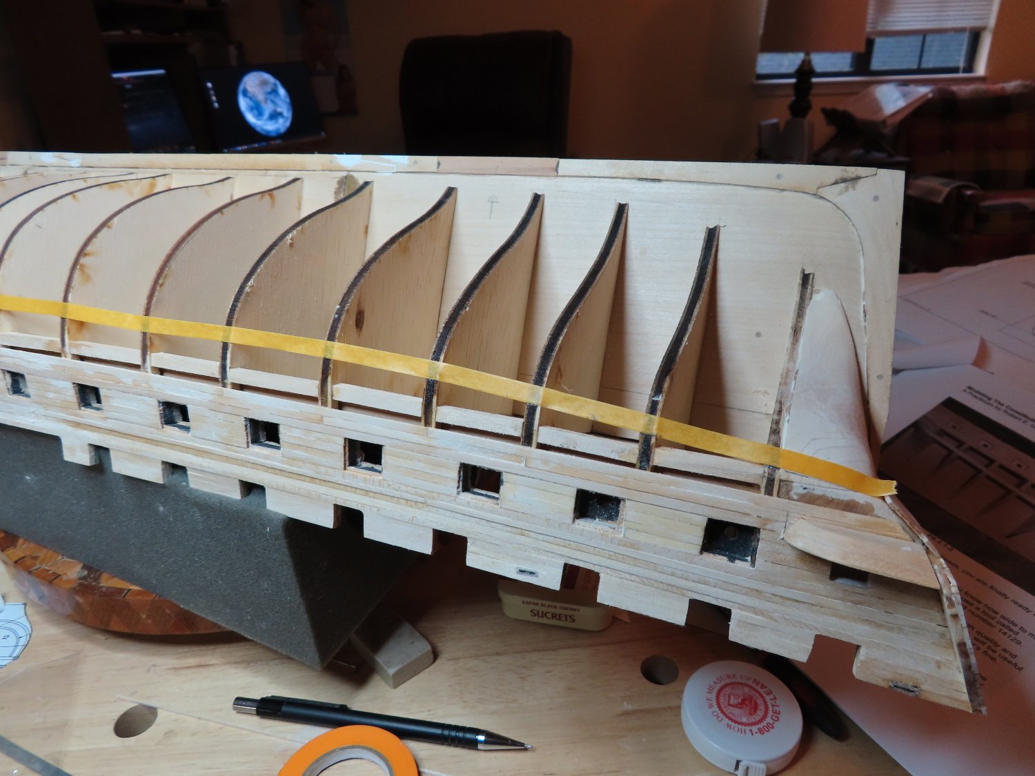
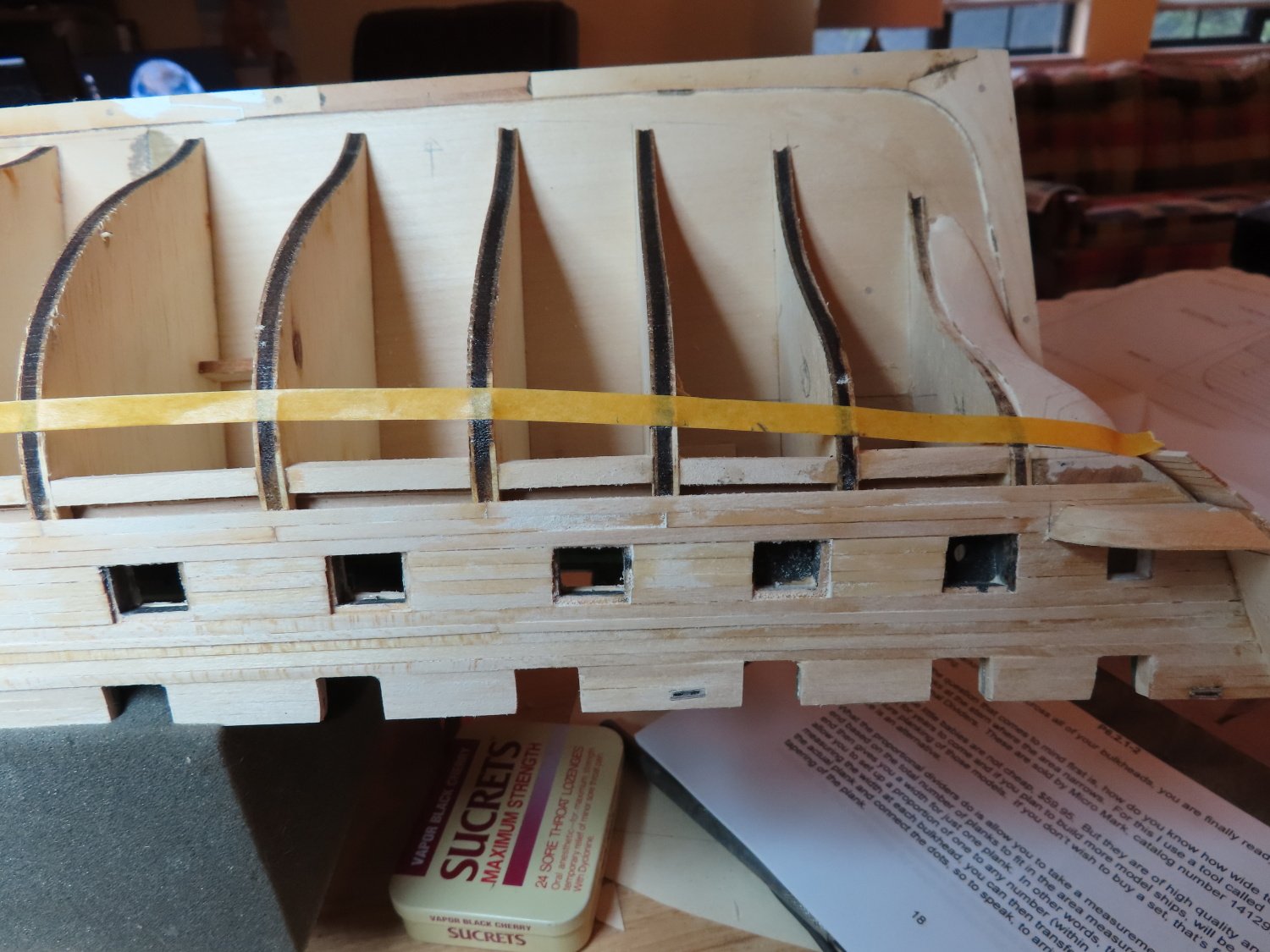
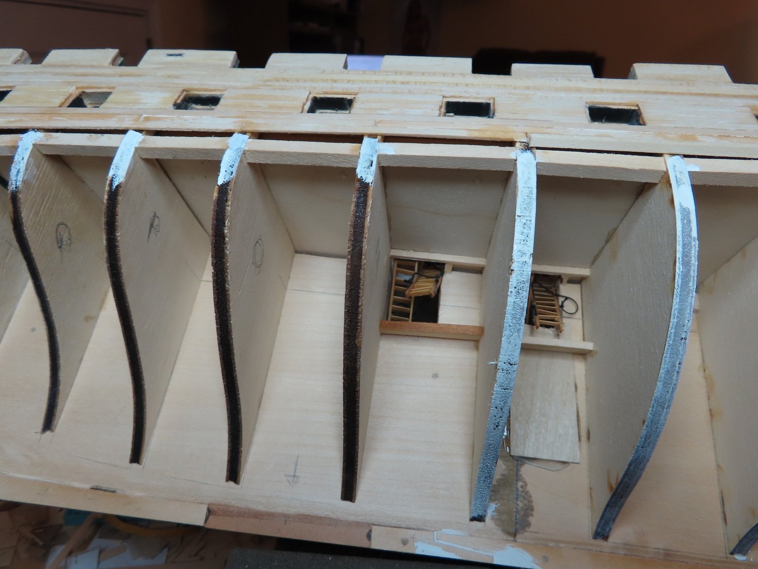
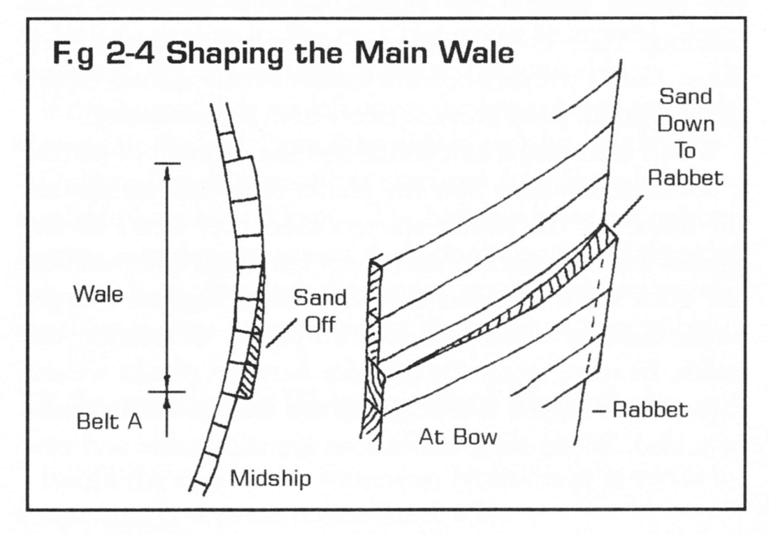
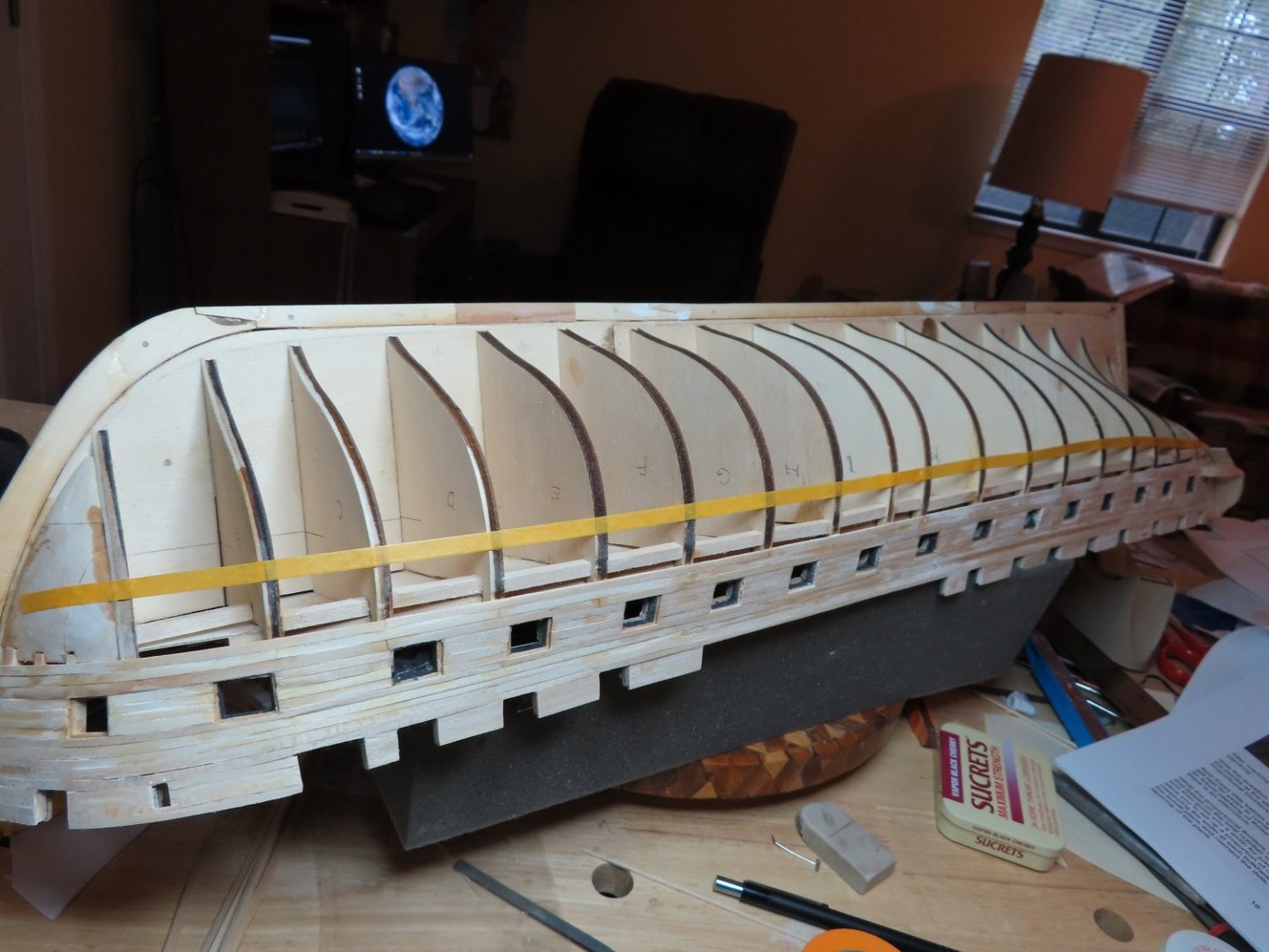
Tape was fragile because there isn’t much surface area on the bulkheads for it to stick to, so I marked the bulkhead where the bottom the lowest plank edge had to follow as indicated by the tape. The pictures above were taken before I painted the bulkhead edges so I could see the tick marks and had to lay out the tape a second time after I paint them. I measured the distance from the bottom of the lowest plank from the gun port band of planking to the tape at each bulkhead from bulkhead N aft and divide by seven, the number of planks that had to fit in that space. That became the individual plank width corresponding to that bulkhead. This took some time Finally, I got all the wale planks installed. But I still have one more thing to do before the wale construction is completed. I must taper the wale to the stem rabbet as well as to the hull planking below the wale as indicated in the instruction booklet.
-
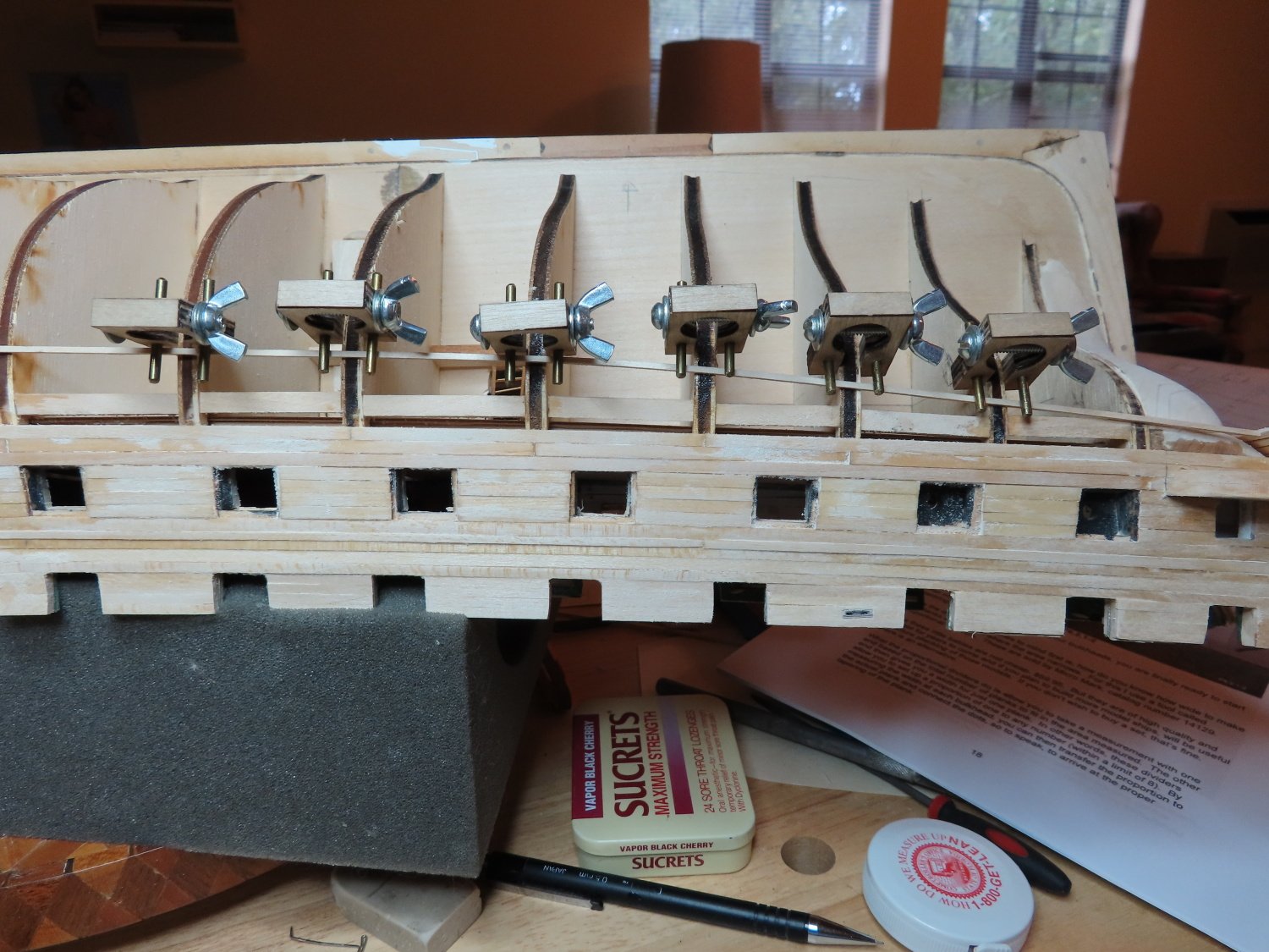
In order to determine the various plank widths, I initially tried laying a planking strip down on the bulkheads and letting it naturally curve up into the transom. To do this I tried using some plank clamps I bought from Model Expo many years ago when I was building the Rattlesnake to hold the plank in position. They were useless then and they were useless now. They are just too clumsy. So, I went to tape.


-
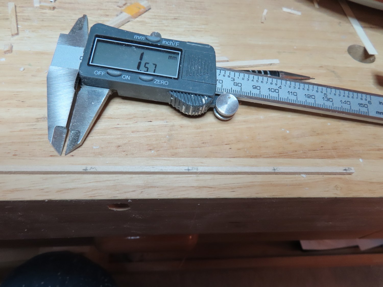
I've seen demonstrations both live and on YouTube and they make seem so easy. That comes with practice, lots of practice and this is only my second planked model! I opted for a third method, a variation of the tick strip. Instead of marking ticks on the bulkhead edges, I marked the planks with the bulkhead position lines and the corresponding width at those locations. Then I sanded down the widths and verified the width dimensions with a digital micrometer at each bulkhead location. Finally, the whole plank was smoothed to make a nice clean transitioned as the plank narrowed.

-
In lieu of this failure, I tried to use the tick strip method but that too had problems. The variations of the plank widths is 3/32" wide to 3/64" at the narrowest width. The pencil tick marks themselves are relatively thick in comparison to variation in plank widths and I better be damn accurate in the tick spacing on the bulkhead edges. I even tried painting the edges white so I could see the tick marks better.

-
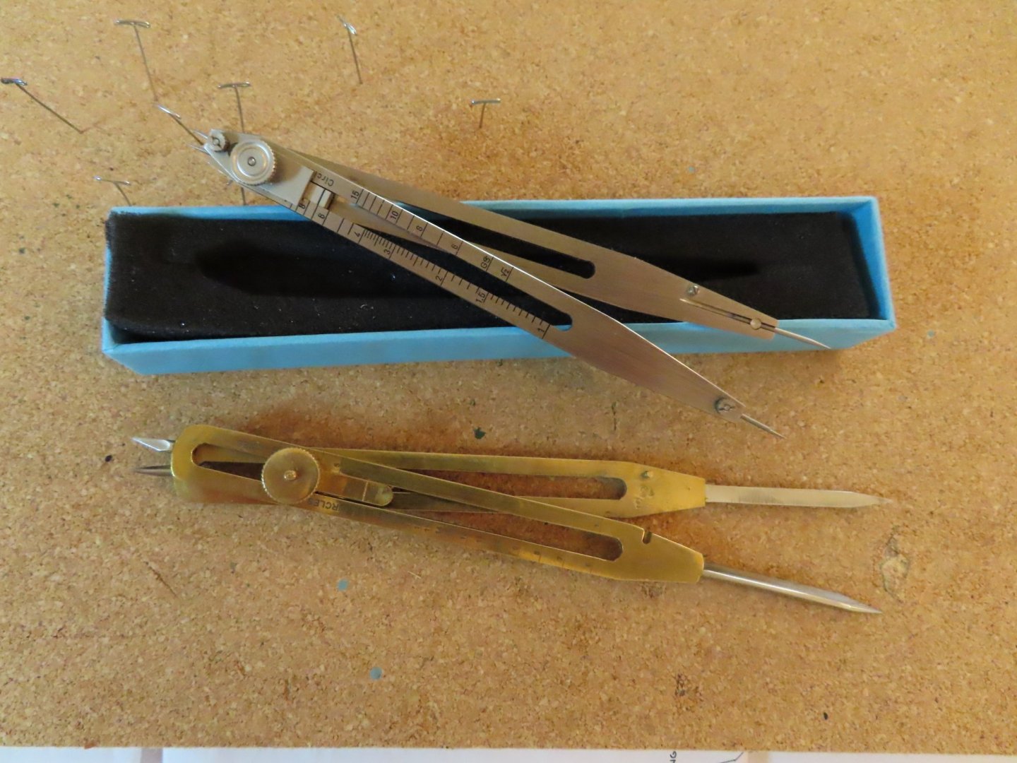
The Wale The wale is the next band in the hull planking process. The wale is made of seven 3/23” wide x 1/8” thick planks. According to the practicum, these planks have no variation in width from the bow up until bulkhead N where they begin to narrow. I had anticipated the plank width variations and had ordered from ebay proportional dividers for this purpose at a price below what Micro-Mark was selling theirs. What I didn't realize was that the supplier was in India. After waiting almost 4-5 months for delivery, I chalked it up as a bad buy and ordered the one from Micro-Mark, which arrived promptly. It looked and operated the way I expected, and I put it back in the box almost two years ago until I was ready to plank. Nine months after my original ebay order, the India dividers arrived! I suspect it got tied up in Customs. I had tried to contact the Seller but all they would state was that it shipped. Now I had two of these dividers. The Indian one was a little bit larger and not as finely finished. When I went to use Micro-Marks', I could not get it to divide as marked on the scales. When I set it to divide by four for example and placed one pointer on the 1' mark and the other on the 5" of a ruler (4" of measure), I'd flip it over and measured with the other end. It should have shown 1" of measure on the ruler. It actually read about 1/32" to 1/16" short. Part of the problem may lie in the fact that I could not lock the legs so they wouldn’t move as I handle the instrument. Where the legs cross there is a tightening screw, but that is for locking fulcrum point not the legs. It was even worst for the Indian made dividers which has cruder increments and the pointers are thicker are blunter. So, either both these proportional dividers are poorly made/designed or I'm doing it wrong. Either way, I'm out a chunk of change as they are useless to me.
-
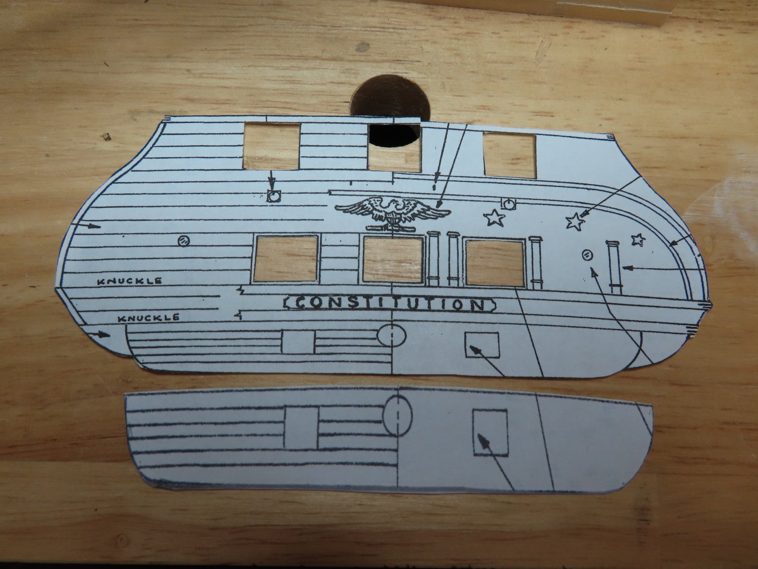
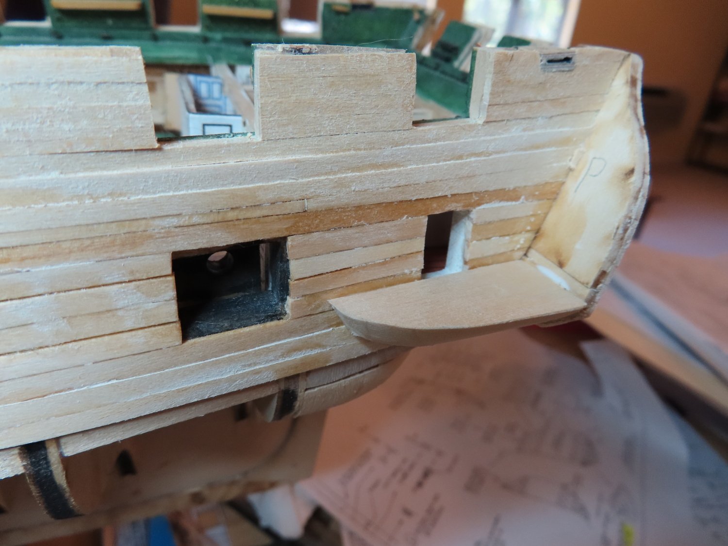
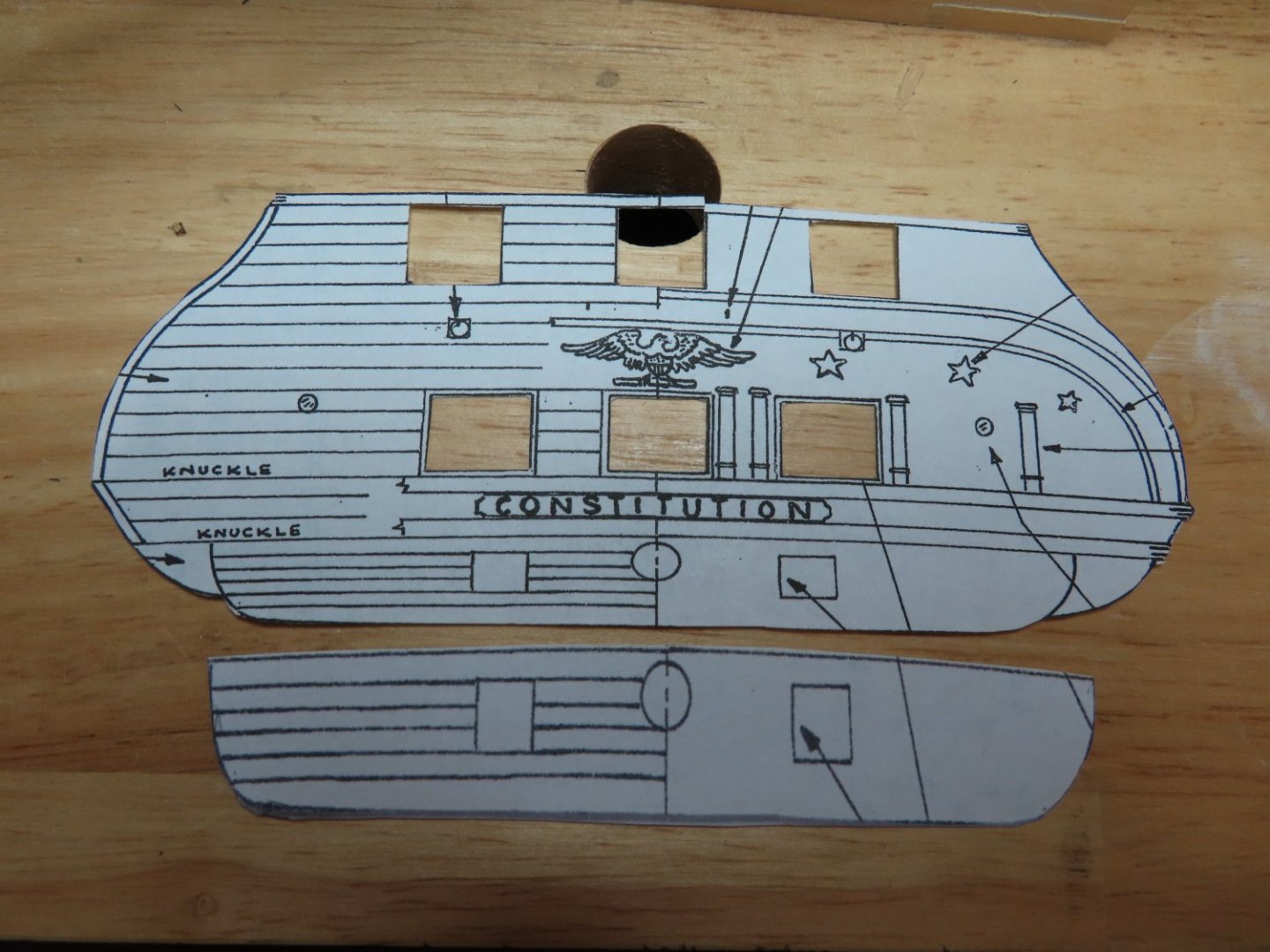
The Lower Transom Counter To finish the planking the lower transom counter, the practicum states: If one takes that statement at its face value, you will run into a problem. The plans show an elevation view. The lower counter is angled away from the viewer and thus is foreshortened. I had to stretch the image vertically so that its height matched the true length of the counter as seen from the side. I ran into this identical problem with the transom when I built the Rattlesnake. I’ve traced out the trim line onto the lower planks but am reluctant to do the trim until I have completed the wale, which it butts up against. Note, there are still two windows which need to be constructed below the gun deck gun port.

-
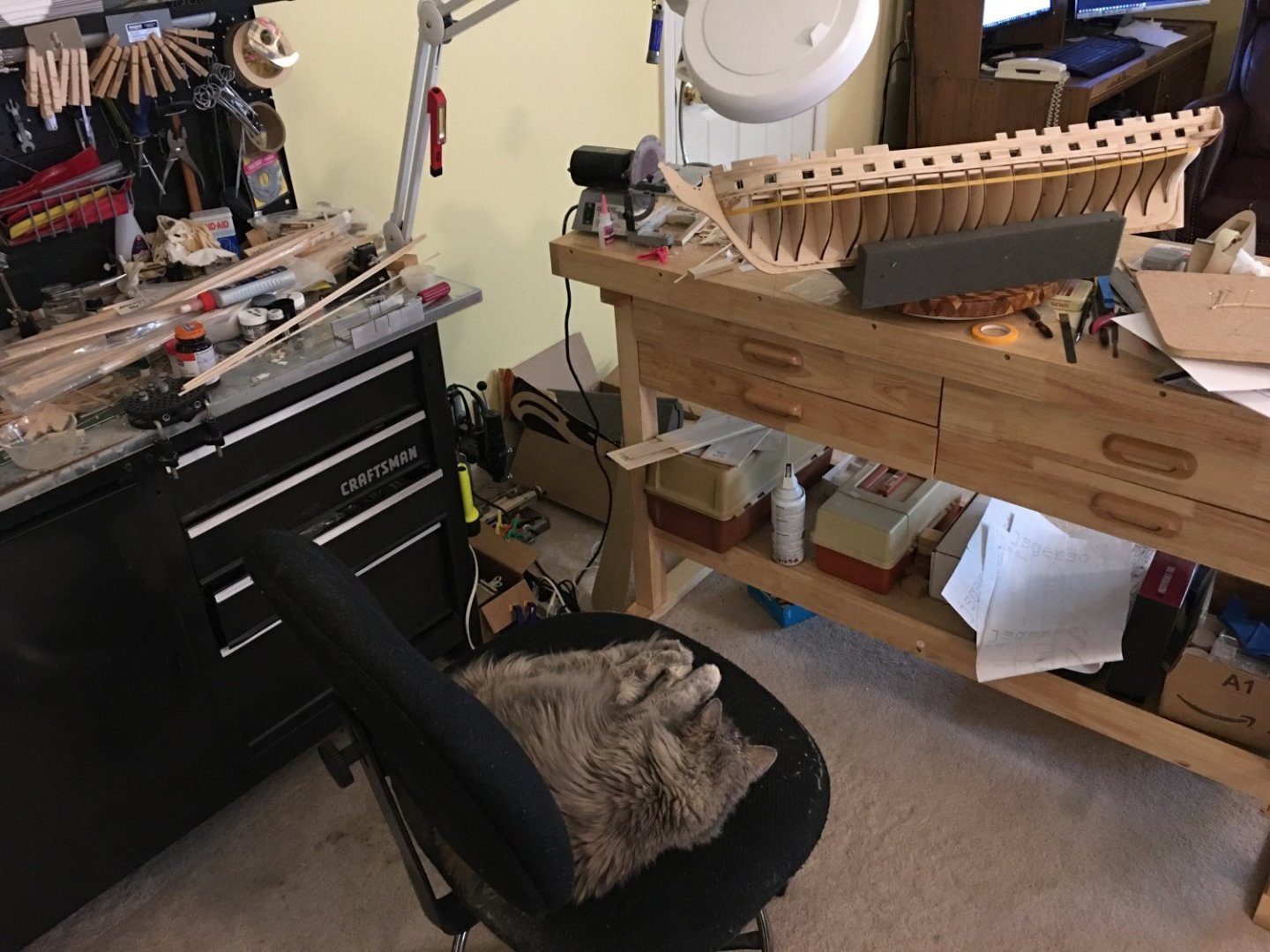
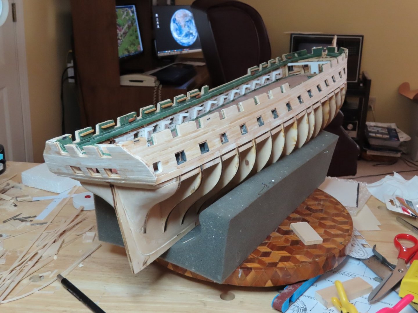
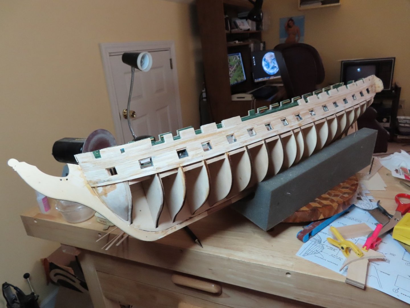
About a month and a half since my last post; I hope everyone is healthy. As many of you know, molasses on a cold day or ketchup pouring from a bottle are faster than I work on my model. One my excuses is illustrated below.
-
Just discovered your build log and that you were inspired somewhat by my build. Just remember, this is only my second square rigged ship build and am prone to make mistakes that I only discover a long time down the road. You are at the point where I believe I made one of those errors. I think my stern filler block (the one where the rudder stem goes through) was too thick. I failed to check the dimensions of the raw block of wood thickness dimensions which I believe lead to my problems with the stern. At the pace you are going, I'll be following you for inspiration. Jon
-
Bob - You are correct in that the instructions leave something to be desired. That is why I am using Robert Hunt's Practicum as a guide, supplemented with various parts of the wonderful build logs on this site. I don't think I would have started this model without their help. I will say this, the kit plans of the ship follow the US Navy plans very closely. Unegawahya - It looks like I will be following you now (assuming you will post a build log), now that you have moved ahead of me in your build. You've done beautiful work. Unfortunately, when I get to the gun deck guns, mine won't be as "easy" as yours. Somehow, my gun deck is either too low or my gun ports are too high which will force me to adjust the gun carriage heights (see early posts). Thank you for showing me your build and I plead with you, post a build log of your work. Jon
-
Very nicely done. Just a point of caution, the gun port lids are very delicate, based on my experience with my Rattlesnake build. They have a nasty tendency to get knocked off due to all of the handling the model goes through continuing the build. Not having reach this point yet in my Conny build, I really don't know if it is better to wait and add them on near the end or do them now as you have because it might not be so easy when all the other stuff is added. Only time will tell. Jon
- 55 replies
-
- 1
-

-
- constitution
- model shipways
- (and 1 more)
-
The bottom quarter galley filler pieces were then trimmed slightly and then glued into place as described by the practicum. Hopefully any errors that remain, and I’m sure they do, are small enough that they can be handled without too much consternation


-
I was able to pry off the bottom two transom planks without too much effort. The new planks were shaped and glued in their place so that at least from the transom point of view, it now level at the bottom edge.

-
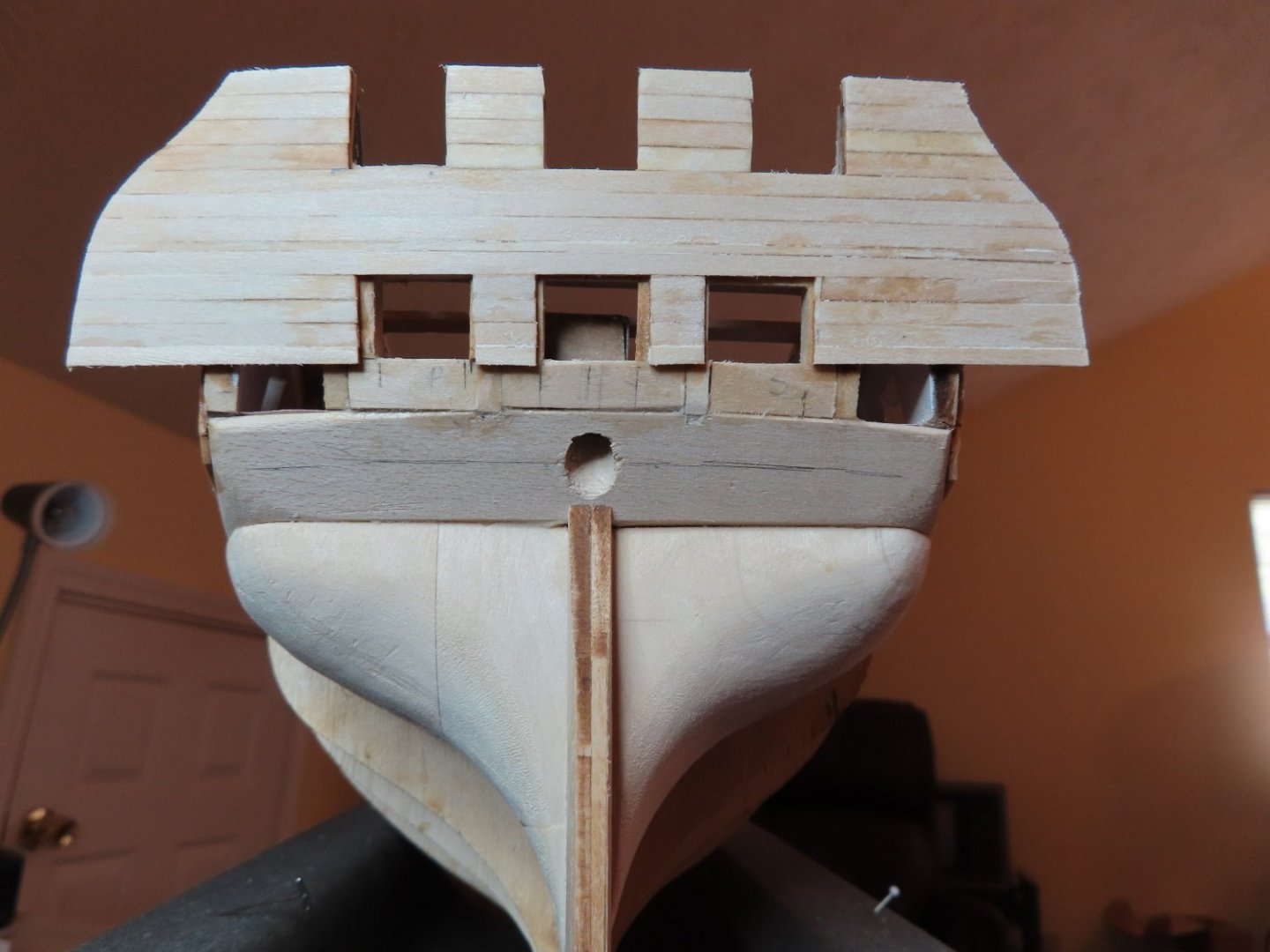
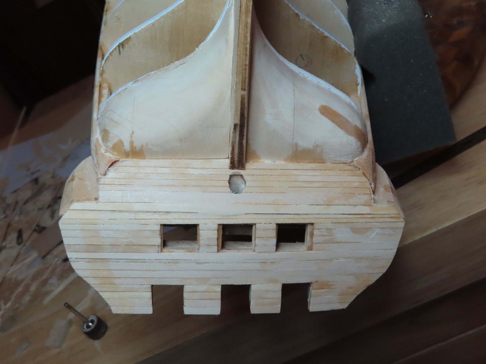
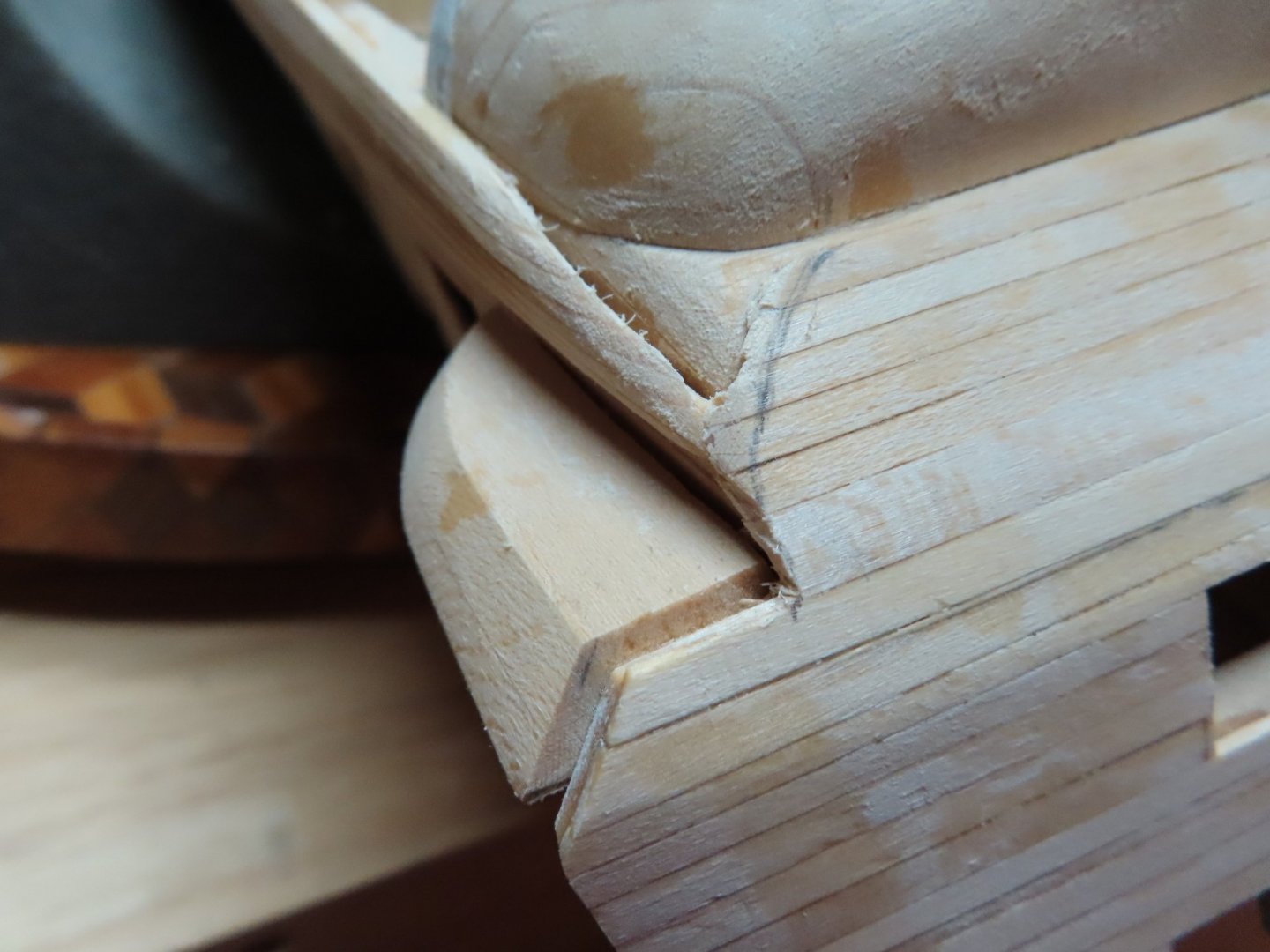
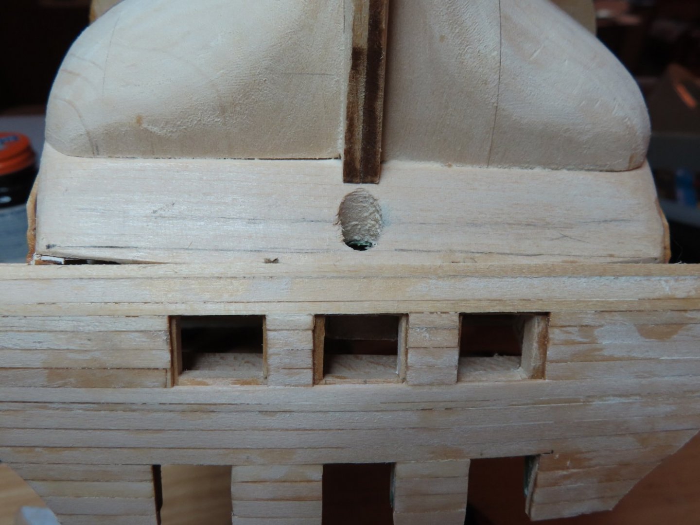
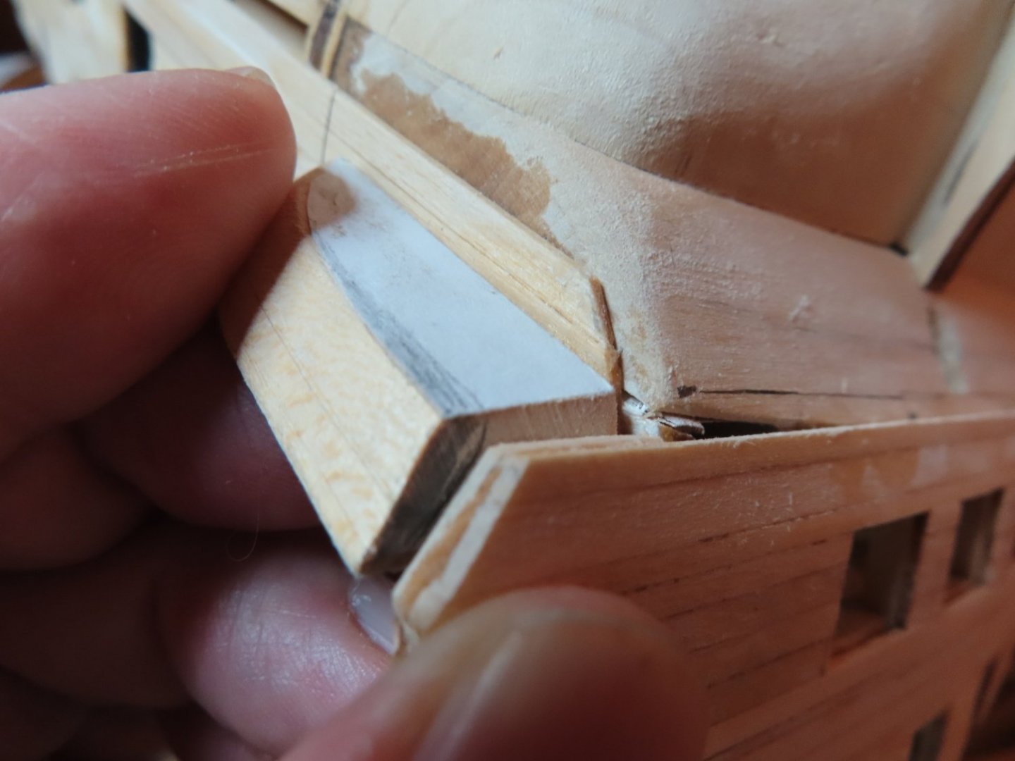
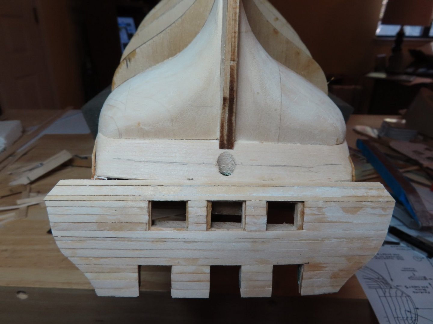
My model is close to following the plans, but not exact enough it seems. The back end of this model has virtually no straight edges from which to measure and the structure is full of curves. My transom seems to be just a bit narrower than the plans so that the filler blocks are a bit too wide to fit as I had cut them out (see my pencil marks on the filler piece). In addition, either my transom is a bit crooked or the area below it is a bit off. See the line I drew just below the rudder post opening. Either way, I’ve got some work to do.
-
That went off without a hitch…so something must be wrong. It’s never that easy. It didn’t take me long to find out what. When I dry fitted the fillers into position, the troubles I had with the transom came back to haunt me.
-
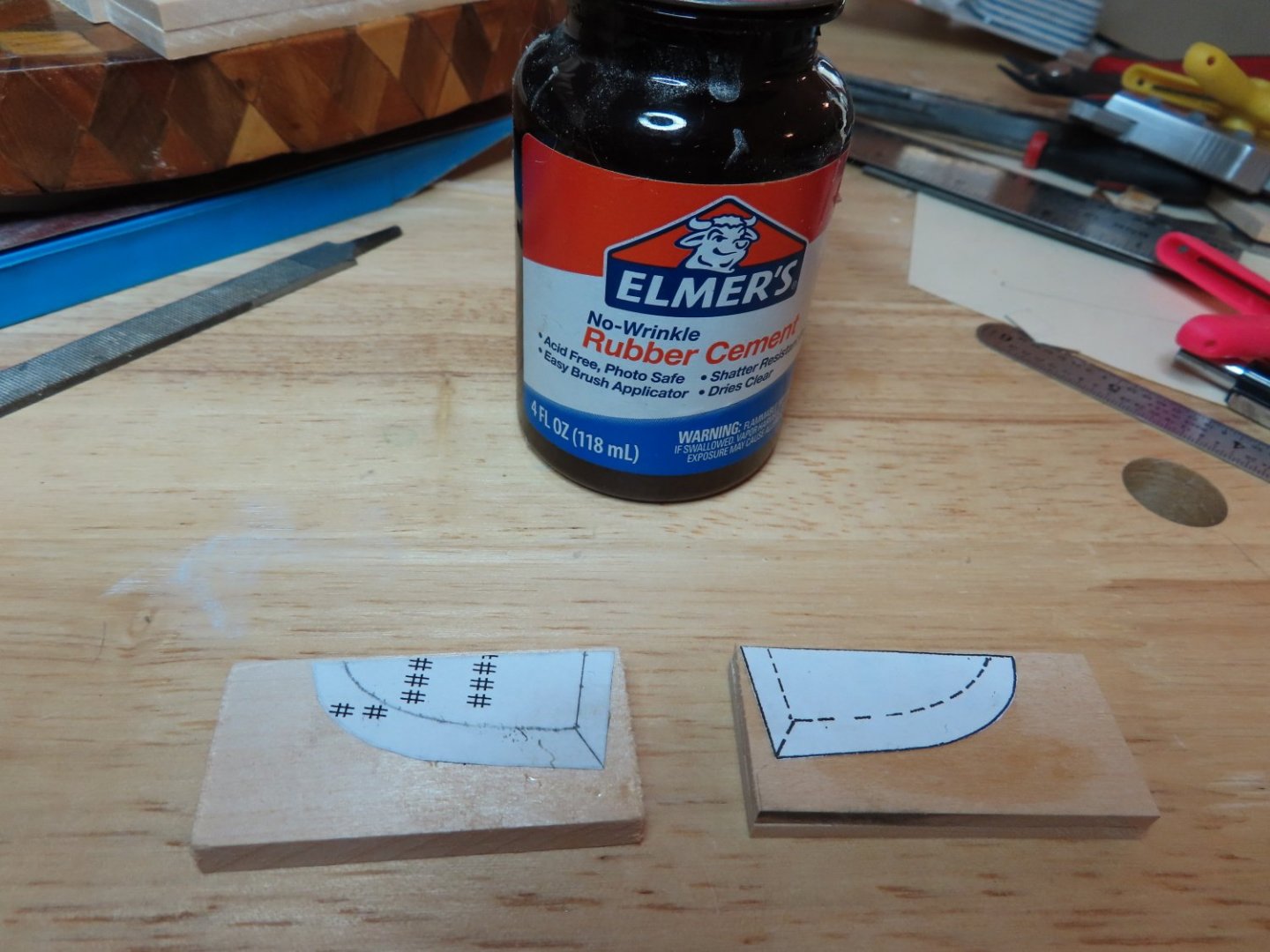
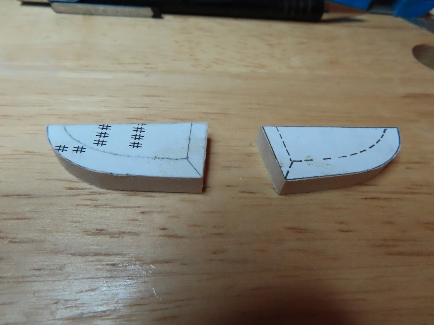
Templates for the bottom filler pieces were made from the plans. First the larger of the two templates and cemented to the billets and cut out. Then a second set of templates were cemented to the bottom of the just cut pieces. Using my disk sander, files, and sandpaper, the bottom filler pieces were formed.

-
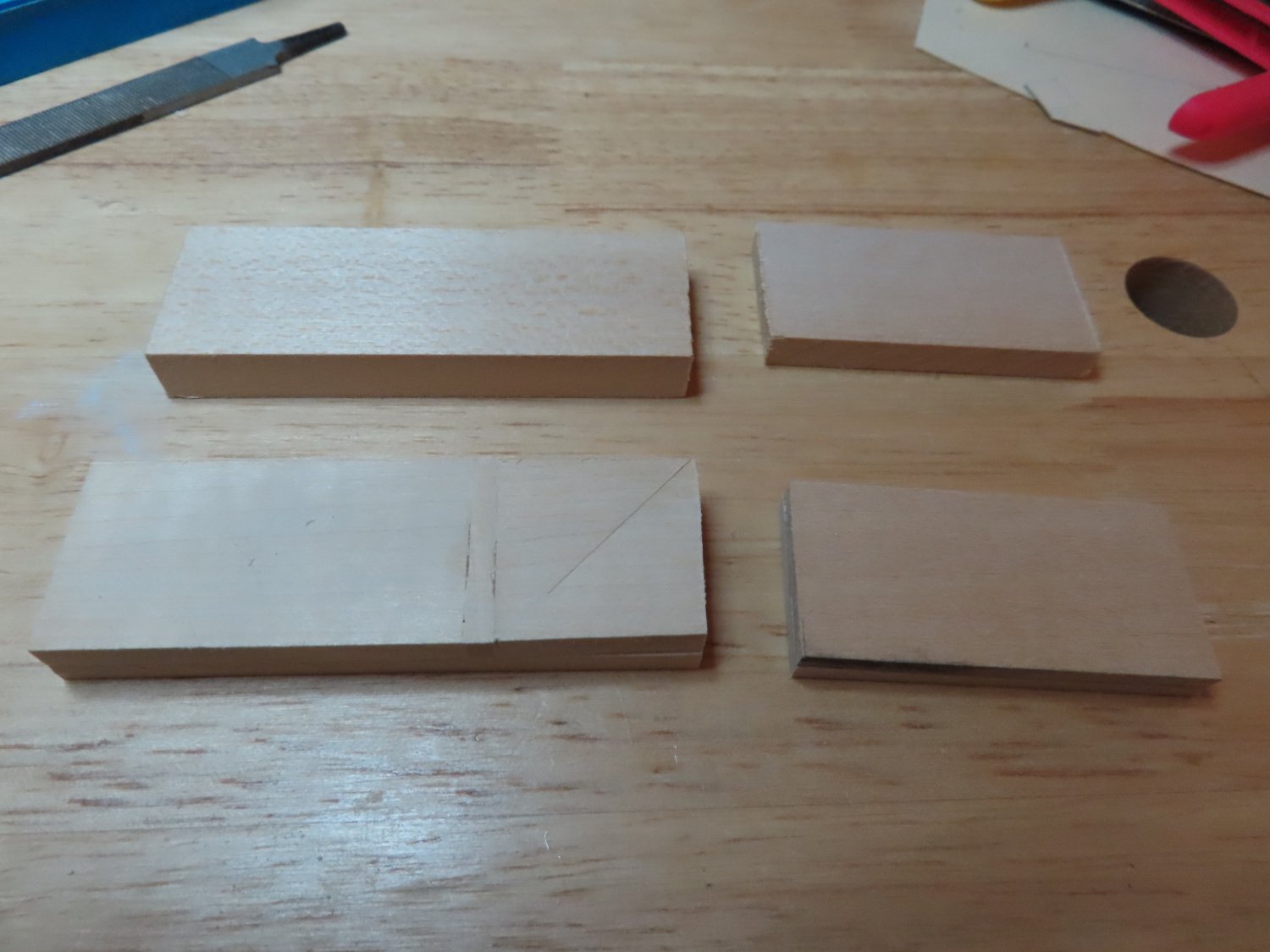
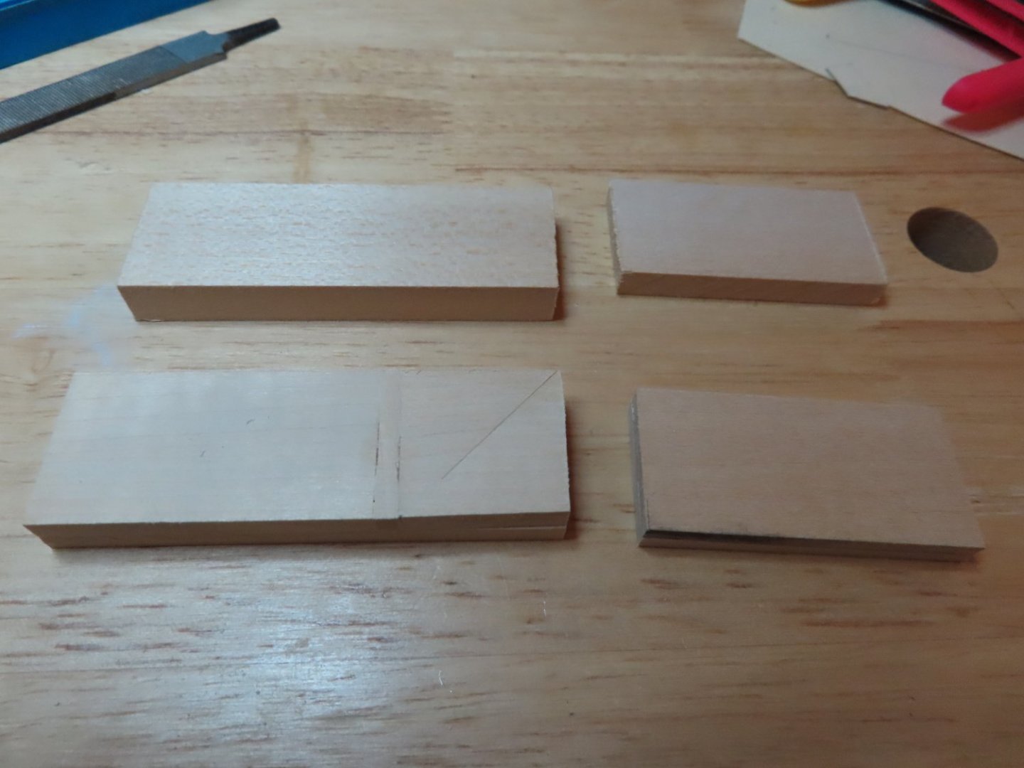
Now for the hard part: The Quarter Gallery Structures. Following the practicum, Mr. Hunt indicated that the kit does not provide enough basswood billets, which I found true. The kit provides one filler block 3/8” x 1” x 3” for the lower side area and one ¼” x 1” x 2” filler block for the upper side of the quarter gallery. That’s only enough for one quarter gallery, there are two. So, he tells the builder to buy more wood. In normal times buying wood is easy, just run down to the hobby store and buy some. But in this newly strange world of the pandemic that’s not possible especially when you live in a small town and all you have is Hobby Lobby. I could have ordered on-line but that adds too much cost due to shipping and you have to wait. However, I did have scrap wood, so I made the additional billets by lamination.
-
That was the easy part.

-
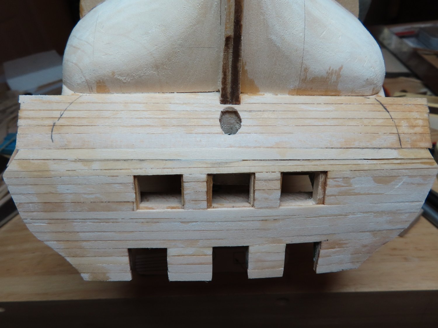
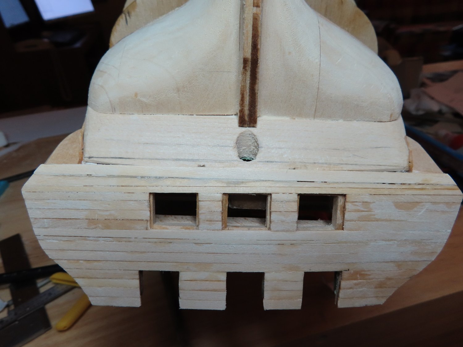
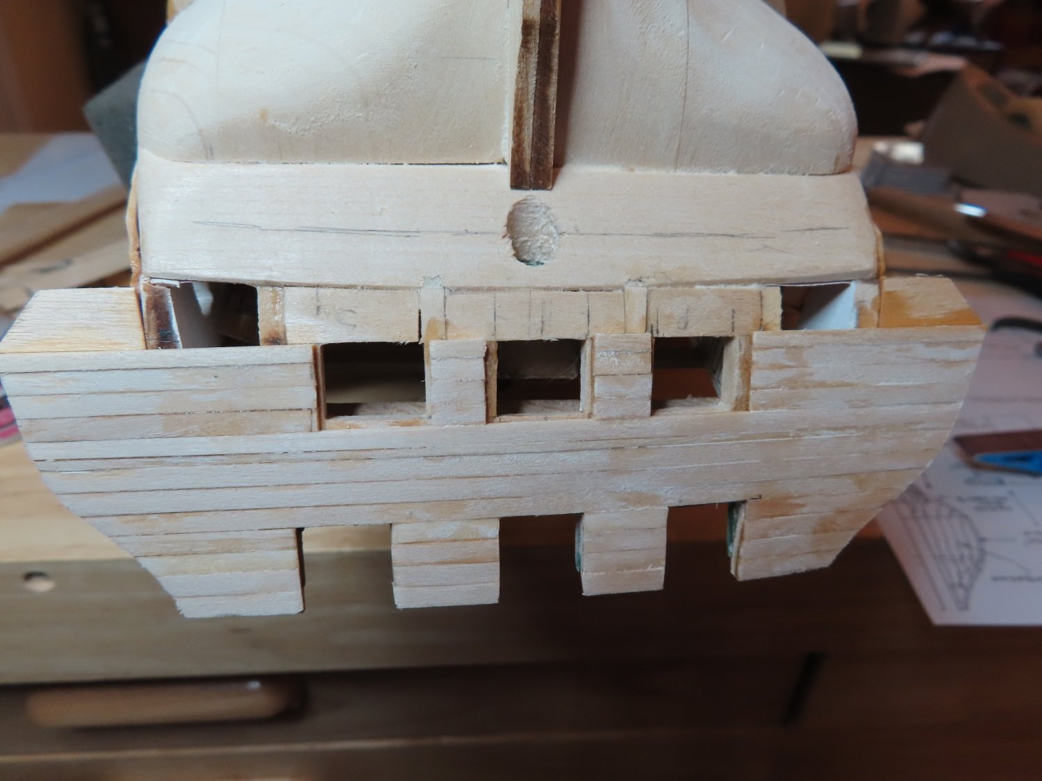
Then the lower transom extensions were added and then planked

-
Finally, I got to work on the transom and the quarter gallery structures. Here, I am paying close attention to Robert Hunt’s practicum because the quarter galleries are a complicated construction. First the transom gun port area (spar and gun decks) were planked.