DONATION DRIVE - SUPPORT MSW - DO YOUR PART TO KEEP THIS GREAT FORUM GOING!
×


JSGerson
-
Posts
2,632 -
Joined
-
Last visited
Content Type
Profiles
Forums
Gallery
Events
Everything posted by JSGerson
-
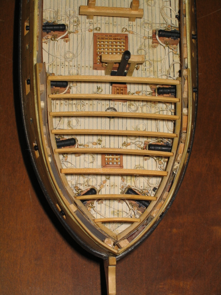
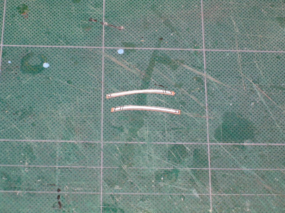
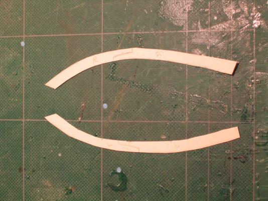
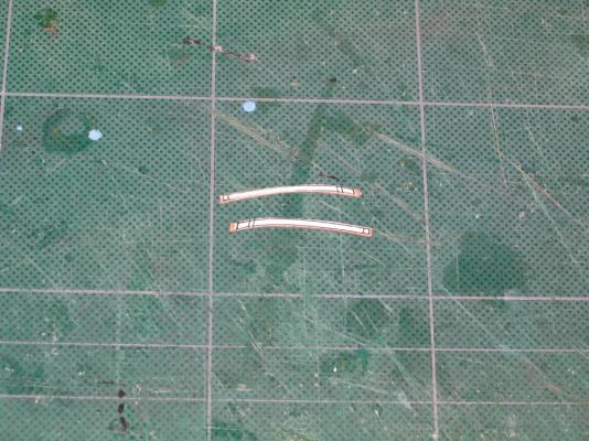
 The pieces were then cutout using my old Dremel scroll saw and finally glued into place. This was not as easy as it appeared. I had a devil of a time getting all the pieces to fit right. I even had to make two of template pieces over again. I got it to work and accepted it, but still not really truly satisfied. If you look closely, where the left scarf joint broke during the cutting process. I got it mended OK, but couldn’t remove all of the glue stains.
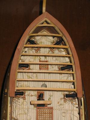
- 974 replies
-
- 1
-

-
- rattlesnake
- mamoli
- (and 1 more)
-
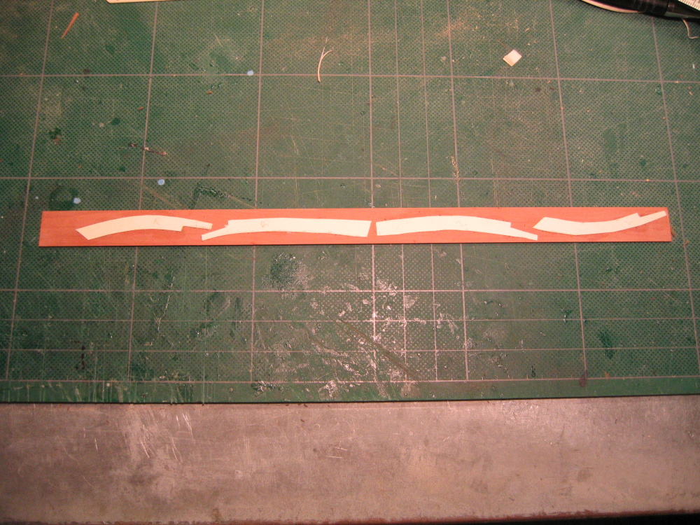
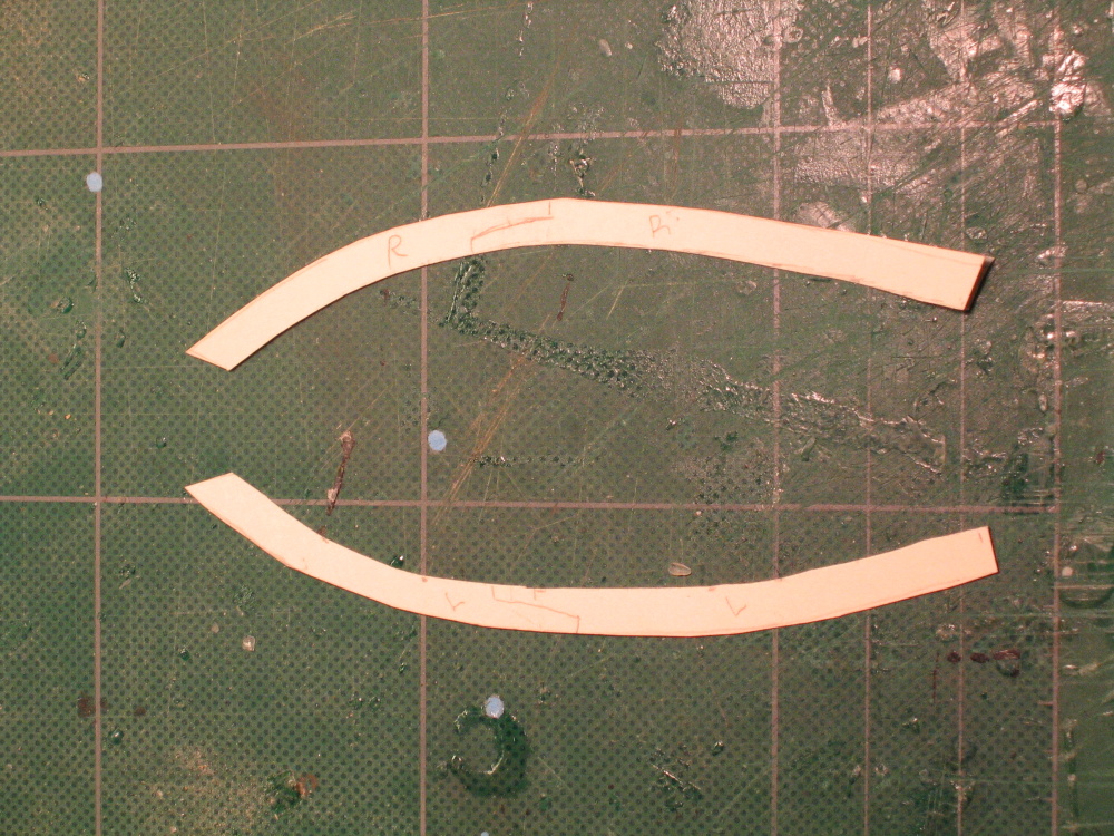
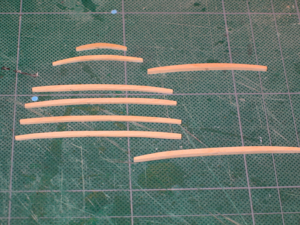
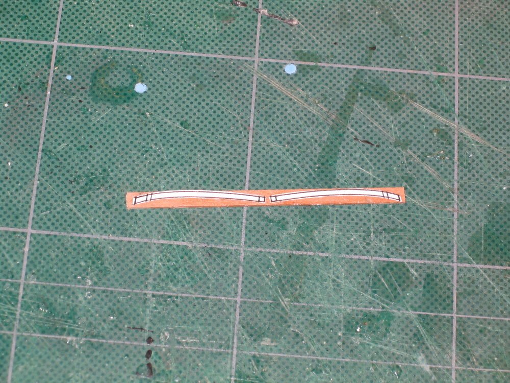
Then because of the severe curve of the bow, each template was divided into two with a scarf joint just like the actual boat. The templates were then rubber cemented to 3/64” x 5/8” swiss pear stock

-
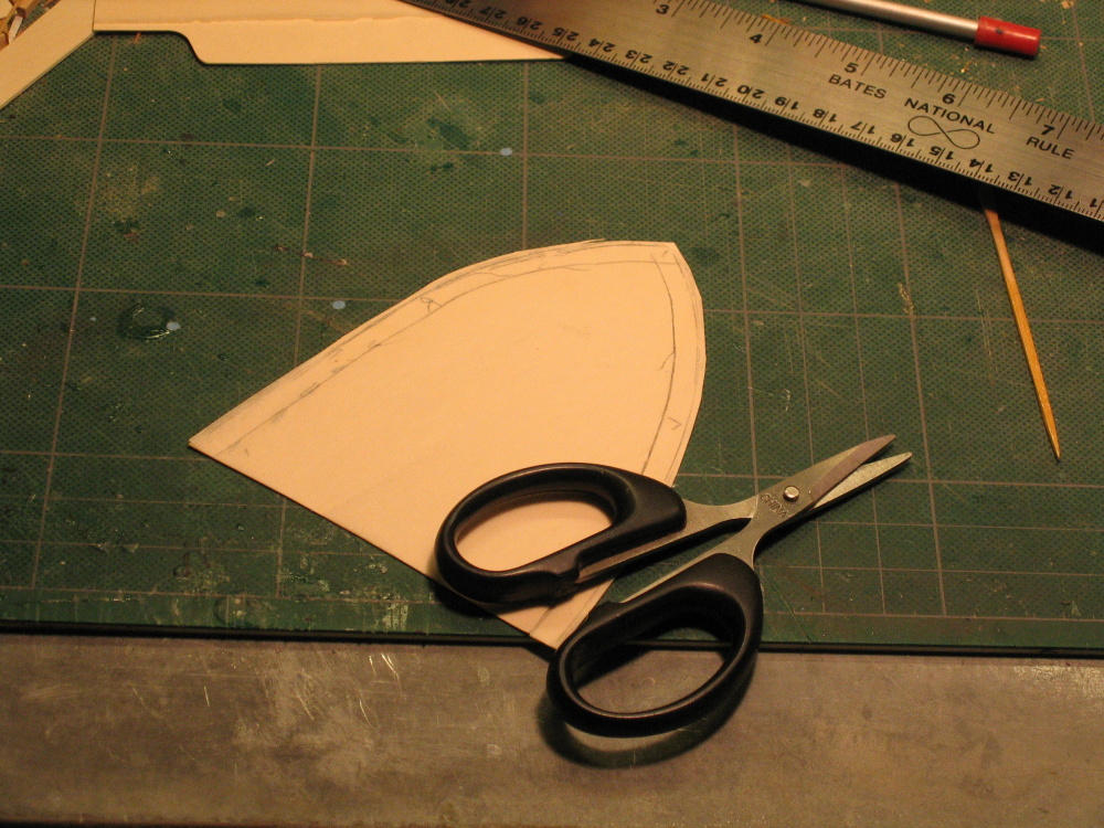
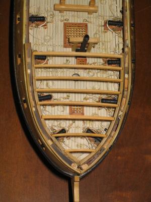
Forecastle Rails This constructed just like the quarterdeck rails. A tracing is made of the outer edge of the hull. Because the outside edge of the rail overhangs the hull by 1/32” the card stock was cutout with the extra thickness on the outside edge. The inside edge is measured about ¼” inside as a parallel line to make the initial templates. The tracing was then rubber cemented to card stock and the excess stock was trimmed and fitted to the bow.


-
Thanks Russ & Martin. I'll use what came with the kit and buy any additional ones if the need arises.
-
Luckily I am not so far along as you are in building Hunt's kitbash, so I can follow in someone else's footsteps. Because your log starts at the rigging stage and therefore does not describe the hull construction, I am curious as to whether or not you used the metal belay pins that came with the Mamoli kit or opted to make your own or buy wooden ones. If you did use the kit's pins, how did you handle the coloring of them (stain, paint, etc.)? I'd be real curious as how you made them if you did that. If you bought them, from whom, what size did you purchase, and were you satisfied with the product? Even though the construction of the pin rails were addressed in Chapter 8 of his practicum, he addresses drilling the pin holes and installing the belay pins in Chapter 9. I've already installed the quarterdeck rail without the holes which I think is wrong and plan to drill the holes before the foredeck rail is assembled, hence my questions. Thanks
-
Now why didn't I think of that, it's so simple!
-
Shhh! If I don't tell the average viewer of the model, they won't know!
-
Any chance you could pass on to the rest of us those plans for the ladder jig? I'm sure a lot of other people are or will have the same problems too. To be fair, I couldn't have done as much as I did without Bob's instructions. They may not be perfect but they are quite detailed for the most part and a whole lot easier to follow than the Mamoli plans. Also, I've have no complaint with HobbyMill's service or products. In fact Jeff Hayes of HobbyMills bent over backwards to make things right. But you are right about the rigging. If you look at the actual model that Bob Hunt made, it has no masts or rigging. He did mention somewhere in the Practicum that he was building four model at once while writing the Rattlesnake practicum, so OK, he cut some corners and I'll cut him a little slack. The rigging is a chapter and a quarter away so I just might look into your foot steps to purchase the MS plans.
-
I asked my nephew this question about the copper tape. He works for a company in Japan (he speaks very fluent Japanese) that deals with adhesives and coatings, matching buyers with sellers of these various products. In other words they match the problem with a solution. He does all their technical translations into English as well as maintain their website. He is NOT a model builder however. He responded: Good question. I've actually never come across copper tape before, but I'll look into it. It's something we don't cover specifically, and if I haven't come across it, that probably means we've never covered it. That said, I can tell you all kinds of things you never knew (or wanted to know) about copper tape. You are correct in assuming that no tape lasts forever. Under specific conditions (mostly sealed conditions) it can last years, even decades. They use all sorts of tapes in construction now, but that is usually for temporarily holding things together until something more permanent is used (screws, etc.). But in a sealed environment, such as that inside an aluminum window frame, it will last as long as your house is standing. In fact, those tapes are often used for waterproofing and not as a structural element, so must be virtually immune to water and moisture. But the big problem with adhesive tapes is two fold. The first is that most are pressure-sensitive, which means they don't even try to be permanent. The second is that it really depends on what you are taping (the adherent). I am assuming you will be working with wood, and very porous wood at that. This means that oxygen will reach the adhesive layer relatively easily, and quickly. This will oxidize the adhesive (not to mention the copper itself), and cause it to become gooey or dry out, depending on the adhesive agent. The difficulty is in finding a copper tape that uses the right adhesive agent for the adherent. Most stick to wood pretty well because wood is rough, but before applying the tape, make sure there is as little dust as possible. This will increase the life of the tape. You could also put a transparent sealant over the tape to increase it's life. I assume you would add a sealant to the ship anyway, so you would want to do this after applying the tape (granted, the solvent in the sealant could dissolve the adhesive, just as the solvent in the adhesive could dissolve the paint it is on and cause delamination). In the Tiffany lamps, the solder is basically used to seal the tape so that oxygen does not reach the adhesive agent. Copper tape is used because copper is heat resistant and conductive and can thus withstand the soldering temperature and bond well with the solder itself. I doubt you could solder copper tape on a wood surface, though. Not that you would want to anyway for the application you are considering. From my understanding of how adhesive tape works and knowing that you would not be working in a nice environmentally controlled area with pressure gradients to whisk away dust as you worked, I would find an alternative. Tape is what is usually called a PSA (pressure sensitive adhesive) and is thus always in a moist state. So I would use a true adhesive that dries completely and copper foil strips. I know that would be more difficult, but if you want it to last years, or decades, to me that seems like the better option. I'll see if I can find anything on existing tapes in terms of durability, but I have a feeling that copper tape is not designed to be applied to wood or organic surfaces (paint, etc), so I would recommend against it. I don't know if I have opened a can of worms, muddied the waters, and befuddled everyone. Let's see if he can come up with a more definitive answer.I would hate to have to glue individual strips with CA glue to get long lasting results.
-
Just one bump? My hat is off to you. Mine is loaded with them. At the time I either didn't know about them till too late, or didn't or couldn't do anything about them. Nothing a little creative photography can't fix. It's amazing what a well placed shadow or cropping can do. 8-). As we have all said, it's a constant learning process.
-
I "discovered" your build log some time ago but hadn't checked up on for some time. I am like you, a first time builder of a POB model, the Mamoli Rattlesnake. I chose the Mamoli kit because I am following Bob Hunt's practicum based on Mr. Hahn's model and plans and doing the complete kitbash. That practicum is based on the Mamoli kit. I thought I either had or could learn the skills as I went. Because I had the practicum, I barely looked at the kit plans. Even though it was the Mamoli model, the practicum did not double plank but used balsa wood filler. I think in my case I should have double planked just to get the practice. I've made a lot of errors and even learn to cover some of them up. When I started this project over three years ago I really knew nothing about wood models (although I didn't know that at the time) and would have loved having all these build logs to read and help me. I'm about 85% complete on the hull now so a lot of the wisdom and experience being discussed I really could have used had I know about it. So keep putting in all the details, errors, solutions, the what ifs, etc. into your log. It's going to help someone, somewhere, sometime. Keep up the excellent work
-
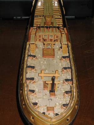
Once dry fitted, sanded, and finished with Wipe-on Poly, they were installed.

- 974 replies
-
- 4
-
-
- rattlesnake
- mamoli
- (and 1 more)
-
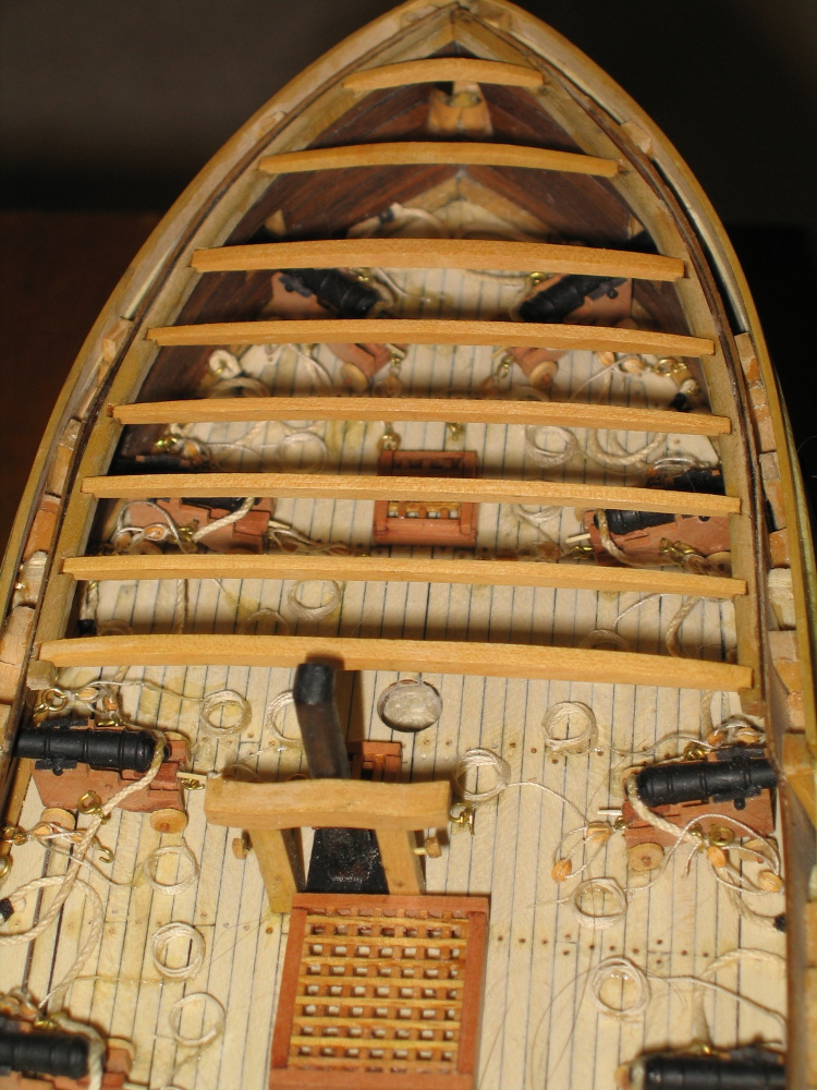
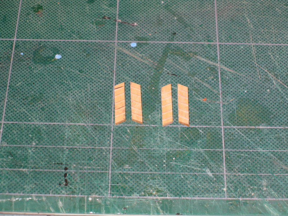
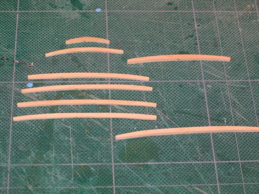
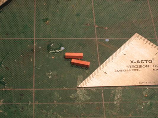
Again the vertical thickness at the ends was 1/16” thickening out at the center to 5/64”. The picture below shows the two wider beams
- 974 replies
-
- 1
-
-
- rattlesnake
- mamoli
- (and 1 more)
-
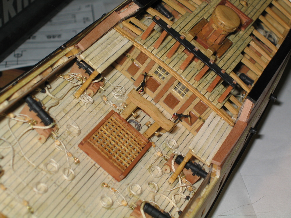
Forecastle Deck Beams The forecastle deck beams were made almost exactly the same way as the quarterdeck beams. The only difference was that two of the beams had thicker widths than the rest. The thin beams (like the quarterdeck) were made of 1/16” x 5/32” and the thicker ones 3/32” x 5/32” boxwood.

-
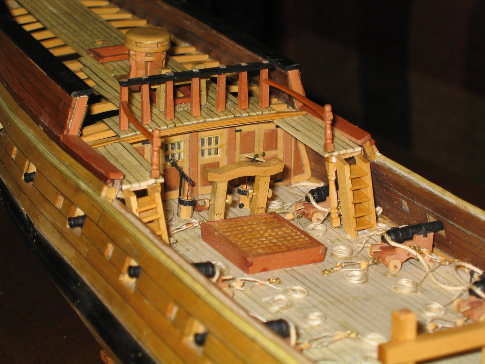
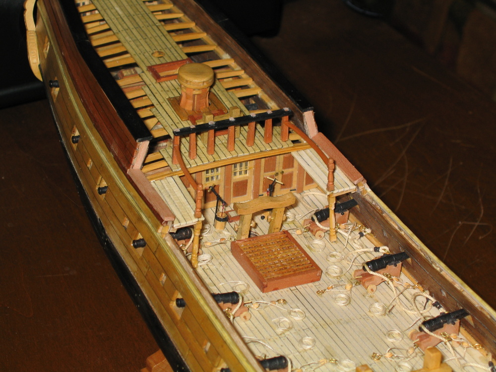
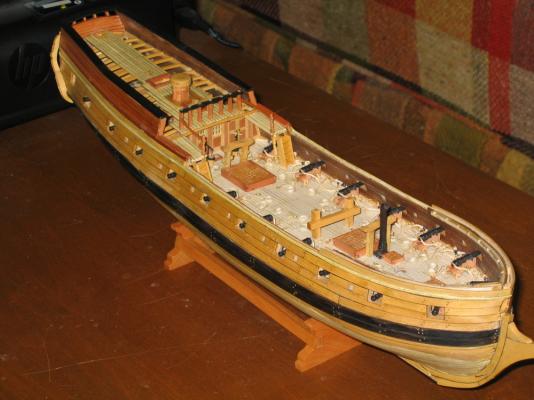
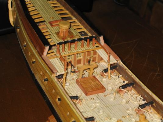
For all intents and purposes, the Quarterdeck is complete...at least for now.

- 974 replies
-
- 4
-
-
- rattlesnake
- mamoli
- (and 1 more)
-
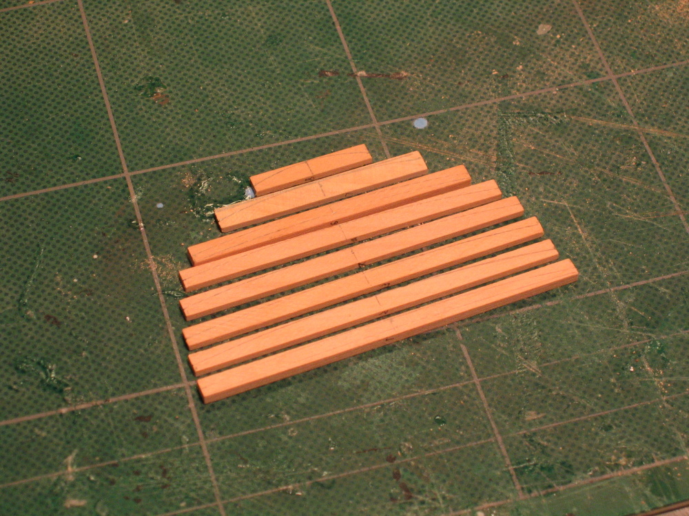
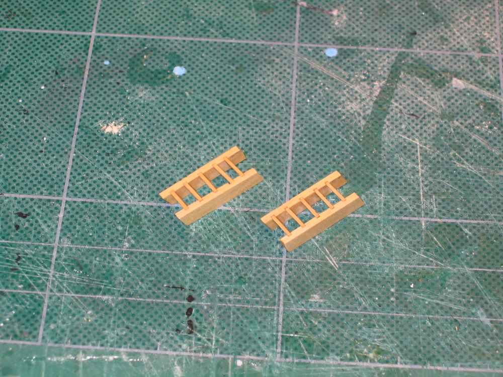
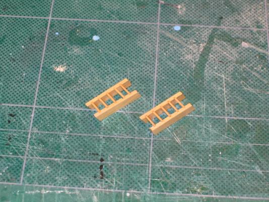
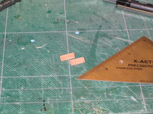
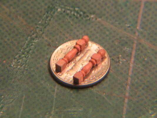
Getting a firm grip on the small pieces is tricky if you want to keep your fingers intact. Anyway, these ladders work.
-
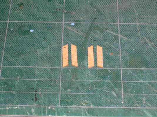
The gangplank ladders were constructed from 1/16" x 3/16"boxwood with 1/32" x 1/4" steps. The angle and width of the ladder was left up to the builder. The only criteria was that the ladder have 5 steps. Up to this point, I've constructed two ladders with limited success, but that was OK. They were mostly hidden once installed. These are out in the open. Once more I attempted to cut the 1/32" (depth & width) step grooves with the Brynes saw. I did a bit better, not perfect, but better. The problem is the pieces being cut are so small, the Miter Extension doesn't get close enough to the blade so I have to extend the extension with a piece of wood.
-
Well I might as well throw my two cents in. I guess it would depend on what time frame the model represents. As you well know, what it looks like today, is not what it looked like in the thirty's never mind what it looked like in 1812. Today the actual ship has a red stripe, in the past it didn't. If the rest of the model represents the ship as it looks today then by all means add the stripe. But that's just me.
-
I'm curious about the copper tape. I have seen other tape from cellophane tape to masking tape to duct tape dry up or get gooey over time. I'm talking decades of years. Does anybody know how the material used for "coppering" the bottom of model hold up? I'm asking because in about a year or so I hope to start my Conny model. It would be a shame if after all the hard work,patience, and devotion to detail were to unravel due to the ravages of time.
-
All it takes is a little practice and patience. Oh yes, it helps to be little crazy.
- 974 replies
-
- 1
-
-
- rattlesnake
- mamoli
- (and 1 more)
-
Well there it is. This build log covers the time span from October 2010 to the present, June 16, 2013 and is now up to date with my build progress. Obviously all future entries will be at a much slower pace. The next step is constructing the gangplank ladders.
- 974 replies
-
- 1
-
-
- rattlesnake
- mamoli
- (and 1 more)
-
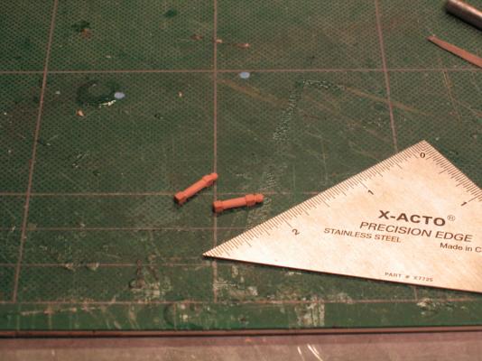
There is a curve handrail from the upper stanchion to the quarterdeck fore rail. Using a copy of the rails from the Hahn’s deck plans to make a template, it was rubber cemented to 1/32” x 5/32” swiss pear. The Practicum however called for 1/32” x 3/32”. I couldn’t see how that would work. If may be as a result the dimension change I made when constructing the quarterdeck fore rail. The pieces were then cut out, trimmed and fitted. The upper surface of the handrail hand the upper edge rounded over while the bottom was kept flat.

- 974 replies
-
- 2
-
-
- rattlesnake
- mamoli
- (and 1 more)
-
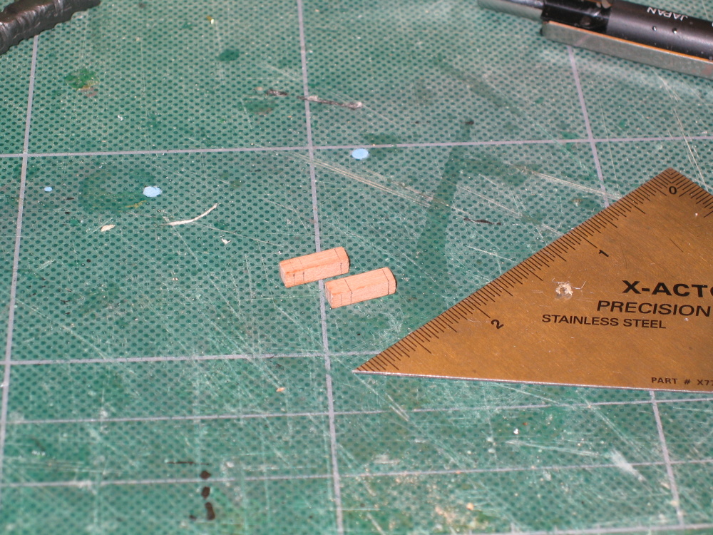
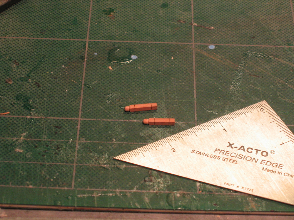
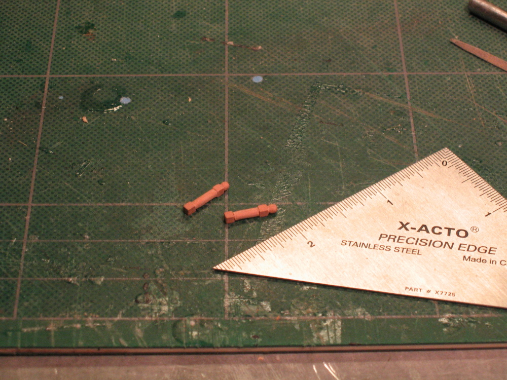
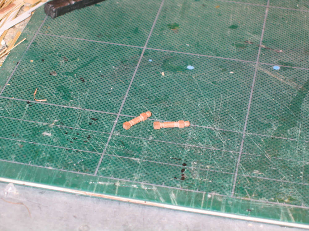
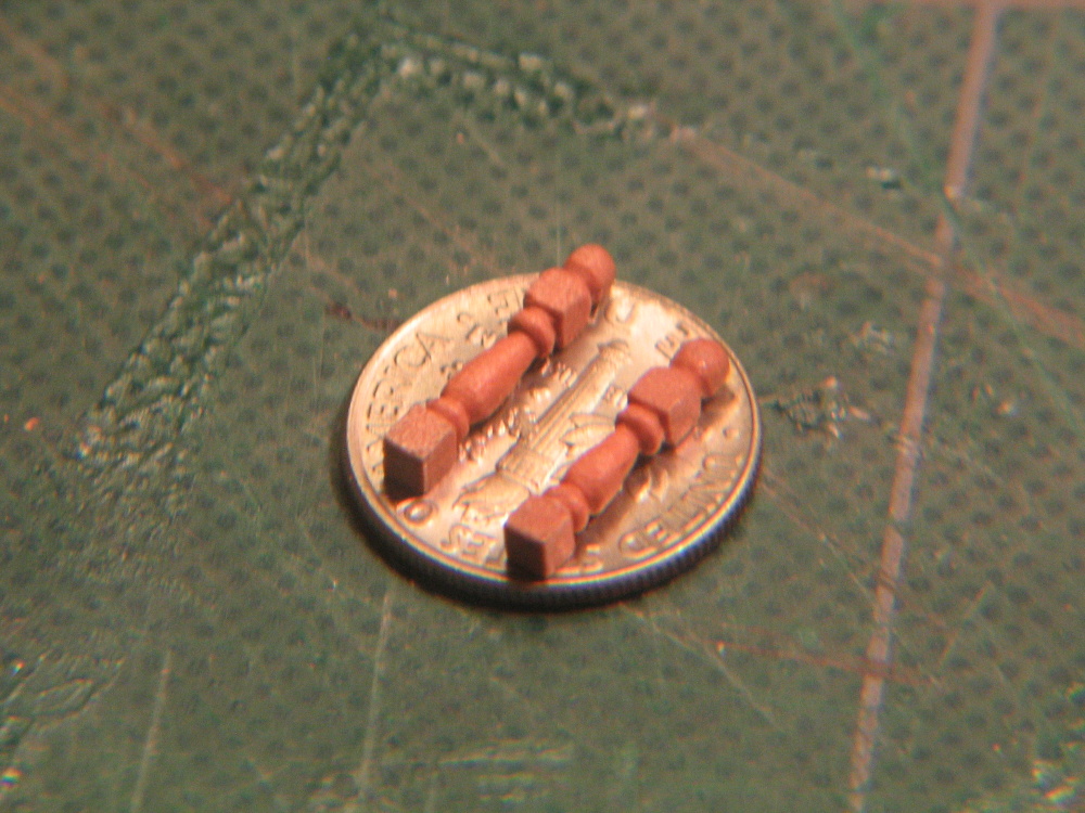
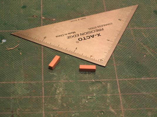
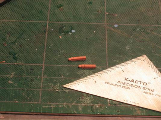
The construction process however is the same as before including the pin the bottom of the stanchion to help affix it to the gangplank.

- 974 replies
-
- 3
-
-
- rattlesnake
- mamoli
- (and 1 more)
-
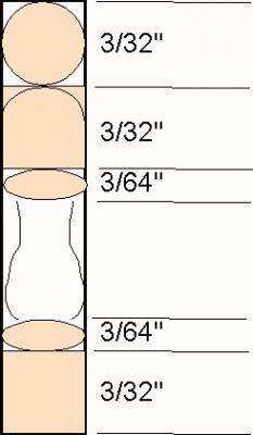
The upper stanchions are the same but different. Instead of boxwood, they are made of swiss pear. The Practicum calls for 3/32” square stock which is not supplied in the wood package (I have informed HobbyMills so hopefully if you purchase the wood package now, it will be supplied.) so I cut down 1/8” square swiss pear to 3/32” square with the Brynes saw. Now it appears to me that the Practicum goes total bogus when describing how to create the upper stanchions. The dimensions provided bear no relationship to the final product. Here is a crude schematic (not to scale) representation of what I did.
-
At this point the Practicum gets a little confusing. There is a decorative hance that needs to be made for each side and installed that provides the transition from the quarterdeck rail to the waist rail. The problem is that the images in the Practicum show the hance on top on the waist rail which at this point hasn’t been installed yet and it won’t be for another 39 pages of the Practicum. Also note that the referenced photo of the hance on page 75, 2nd paragraph has a typo. Instead of P8.1.11-17, it should be of P8.1.11-16. This will be tackled at that point. The outer rails were then installed.