
HOLIDAY DONATION DRIVE - SUPPORT MSW - DO YOUR PART TO KEEP THIS GREAT FORUM GOING! (Only 36 donations so far out of 49,000 members - C'mon guys!)
×


Seamus107
-
Posts
140 -
Joined
-
Last visited
Content Type
Profiles
Forums
Gallery
Events
Everything posted by Seamus107
-

Where can I get small grommets?
Seamus107 replied to Seamus107's topic in Masting, rigging and sails
You are correct, it is the thimbles I am looking for. I am sorry to hear that no one making miniature versions any more, Inhave found them useful. Thanks for the clarification and information. -
I am down to the last four mini-grommets from my late father’s ship modeling supplies. Their outer diameter is 3/32, which means the hole is about 1/32. I have looked around for a source to get more, but have had no luck. Any ideas from this very experienced group would be appreciated. Thanks. james Maine
-
Just tuned in to this building log for the Bounty launch. Good work so far, looking forward to seeing your progress in future posts. james
-
Sometimes I cover about 1/4” of the end of a line with super glue and, when the glue dries, cut the tip at an angle to yield a sharp point. Usually I can then get the stiff, pointed tip through an appropriately sized hole. If the tip bends or frays, I re-cut a new point a little ways back and try again. james Maine
-
Making aluminum look galvanized?
Seamus107 replied to CPDDET's topic in Metal Work, Soldering and Metal Fittings
I used a spray product called Dullcoat to make aluminum tape look like zinc, worked fine. james -
I like to use Lego blocks when gluing up frames. They are perfect right angles, can be assembled into jigs of various configurations, have good surfaces for clamping, and are resistant to wood glue. For my current model, I glued 28 frames to a false keel, starting at the bow and working toward the stern, one at a time, moving the Lego jig along as I went. Works well for me. james Maine
-
The name shown on the bow of the model kit, “James Caird” is not correct. I contacted an archivist at Dulwich College, who confirmed that names were painted on the bows of all three boats salvaged and repaired by Shackleton, and that the name painted on the boat that made the journey to South Georgia was “J Caird”. In one of Frank Hurley’s photographs of the Caird launch from Elephant Island, the name “J Caird” is visible at the bow. The kit manufacturer should correct this error before the kit is made available, if they claim that their model is historically accurate. james Maine
-
I should have been more clear in my initial post. Modelers Central is OFFERING the kit, not making it, as the above comments indicate. I was excited and posted the first news I heard about a James Caird kit, without digging into the details about the kit manufacturer. Sorry about that. james Maine
-
Modelers Central is coming out with a James Caird model kit in 2022. Details (although not many) can be found at https://www.modelerscentral.com/modeling-hub/james-caird/. Looks like a good, realistic representation of the Caird, with a cutaway hull to show ballast, crates, supplies, etc., in the crowded boat. james Maine
-
I have arrived late to this build, and am impressed with the work done thus far. You do not seem to be afraid to admit mistakes and are clear about how you address them. Very commendable. The Endurance is part of a great Antarctic survival story, and is a truly historic ship. I am looking forward to the next steps. James
-
17th Century Shallop by ryesbeemer
Seamus107 replied to ryesbeemer's topic in - Build logs for subjects built 1501 - 1750
It has been a while since you posted about this model. Do you have any updates for the group? -
Could you share the plans for the Mayflower shallop that are in the background of the pictures (rudder, etc.) in your February 15, 2014 post? I know I have asked tou about shallop plans before, but those look very useful to someone hoping to model this boat. Thanks.
-
Chuck, Did you darken the edges of the planks to define the planking? In some of the closeup shots, it looks like the seams are a little darker than just a shadow. Beautiful planking, regardless. James Maine
- 421 replies
-
- 5
-

-
- medway longboat
- Syren Ship Model Company
- (and 1 more)
-
I am planning a 1/24 scale diorama that will include part of a square-rigger mast and at least one spar, maybe two. Given my chosen scale, It is critical for the sizes of the rigging lines and pulleys to be as accurate as possible. Any suggestions about where to find information about the actual sizes of pulleys and the full-sized diameter of rigging lines on fully-rigged ship would be appreciated. Thanks.
-
Looking forward to seeing your posts on MSW, as well as the real thing at the MVSMC meetings!
- 28 replies
-
- 3
-
-
- bellerophon
- 74 gun
- (and 1 more)
-
Zinc-plated hull
Seamus107 replied to Seamus107's topic in Building, Framing, Planking and plating a ships hull and deck
This is a follow-up to my query about zinc plating. To simulate zinc plating on my Mount's Bay lugger model, I ended up using aluminum foil tape purchased at a local big-box building supply store. According to the manufacturer, the adhesive on this duct repair tape was good for a wide range of temperatures, from below freezing to well above boiling, so I figured it would sick all right to the smoothed, primed hull of my model. I cut scale rectangles to represent the 14" by 48" plates, and embossed them around the edges using a pounce wheel to represented the nail heads. I realize that this is not quite correct or realistic, since the nail heads would have been flush with the surface of the plates, or even recessed a little, but I felt that the visual effect of slightly raised nails was important to the overall look of the model. The aluminum foil tape was very shiny, but all it took was a spray with Dullcoat to give the plates a pewter-like appearance, close enough to the appearance of zinc plates. Below is a photo of the hull, after finishing the application of the plates and spraying with Dullcoat. As I worked up from the keel and forward from the stern, I let the plates follow the curve of the hull, but the topmost row was applied along the waterline. In the photo, the rudder is in place, sheathed with foil plates below the waterline to match the hull, but has not yet been sprayed with Dullcoat. The effect of the Dulcoat on the shiny aluminum plates is clearly apparent.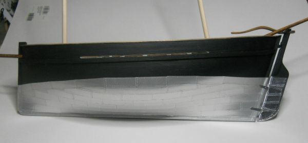
-
I am building a model of the Mystery, a Mount's Bay lugger that sailed from Cornwall to Australia in 1854-55. Apparently the hull was plated with zinc before this voyage. I would appreciate whatever advice MSW members can give me about how best to model zinc plating. Thanks. James
