Supplies of the Ship Modeler's Handbook are running out. Get your copy NOW before they are gone! Click on photo to order.
×

CharlieZardoz
-
Posts
969 -
Joined
-
Last visited
Content Type
Profiles
Forums
Gallery
Events
Everything posted by CharlieZardoz
-
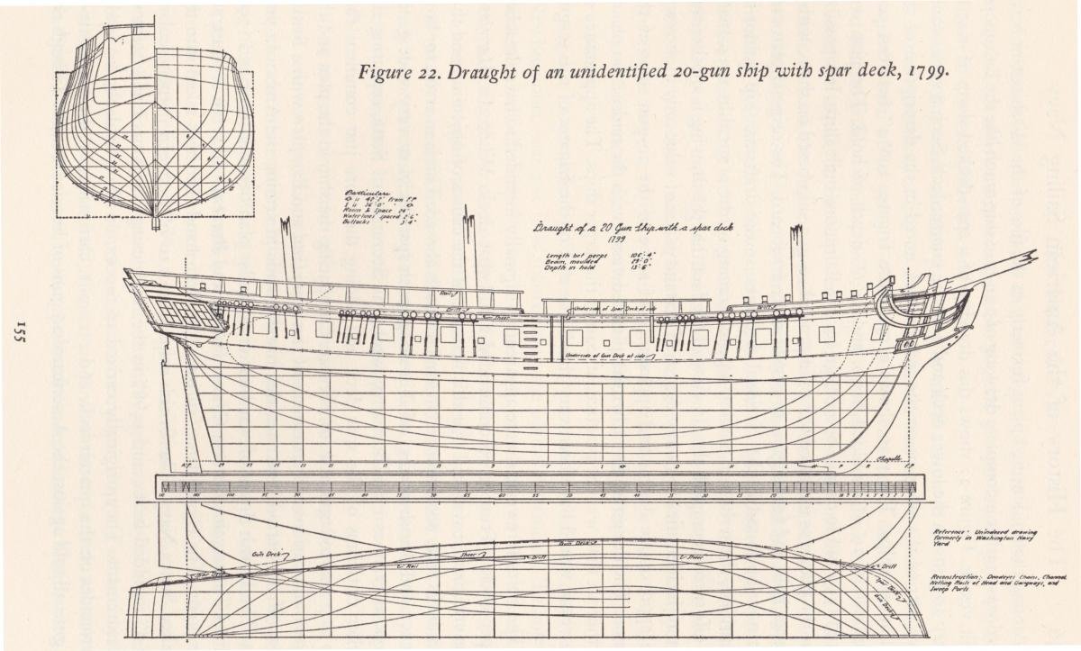
 Greetings Mr Wells! I agree with you regarding the overuse of the Doughty design, while I see it as a typical example of revenue cutters at the time, what my impression is that the design is only a snapshot of some of what was built at that time. First off all the ships of the Northern waters like Alert had very different dimensions and likely not even based off the design at all. The southern ships as well had variations and as the years progressed up to the 1820's I expect most of those cutters if not built with full bulwarks (with cannon ports) had them added and modified accordingly. My assumption is that later ships like Vigilant probably had full bulwarks and resembled a cross between the 80 ton cutter and the Morris/Taney class that succeeded them. This makes doing the actual history a bit tricky and it is my intention to build the 3 Doughty cutters based off the plans and have each be representative of a ship and variation of a design at that time using my own inferences based on what ive read. I know that Active was not likely to have been a Doughty cutter however since I know of no other ships at that time with a tonnage so low and also because the ship had an interesting history I decided to name the model I'm making the Active under the assumption that the Doughty design is representative of how she "may" have looked. There is an error in Chapelle's books where he refers to Active as Alert which is why I think all those kits use the Alert for the 30 ton cutter, it should have been the Active. So the other two Ill name Monroe and Vigilant to coincide with that passage that Irving wrote where the Active sailed with the two ships in 1824 on the way to her retirement. This will be a mural with all 3 lined up and while my approach isn't "good history" it's more like Hollywood history which I'm going into this with full disclosure. So with that said I am happy to listen to any advice you have regarding how I could make these designs appeal to me as a model maker but also offer a sense of realism regarding the service these ships actually fulfilled. Ie ruling out what wasn't possible vs what may have been possible as the history of these ships seems extremely sparse. So for example the color scheme is something I'd love some help with I'm assuming black, tallow and wood were the primary colors by 1818-1825?
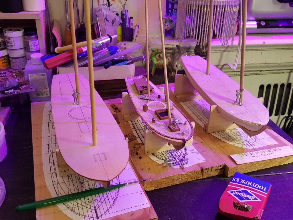
- 362 replies
-
- 2
-

-
- active
- revenue cutter
- (and 1 more)
-
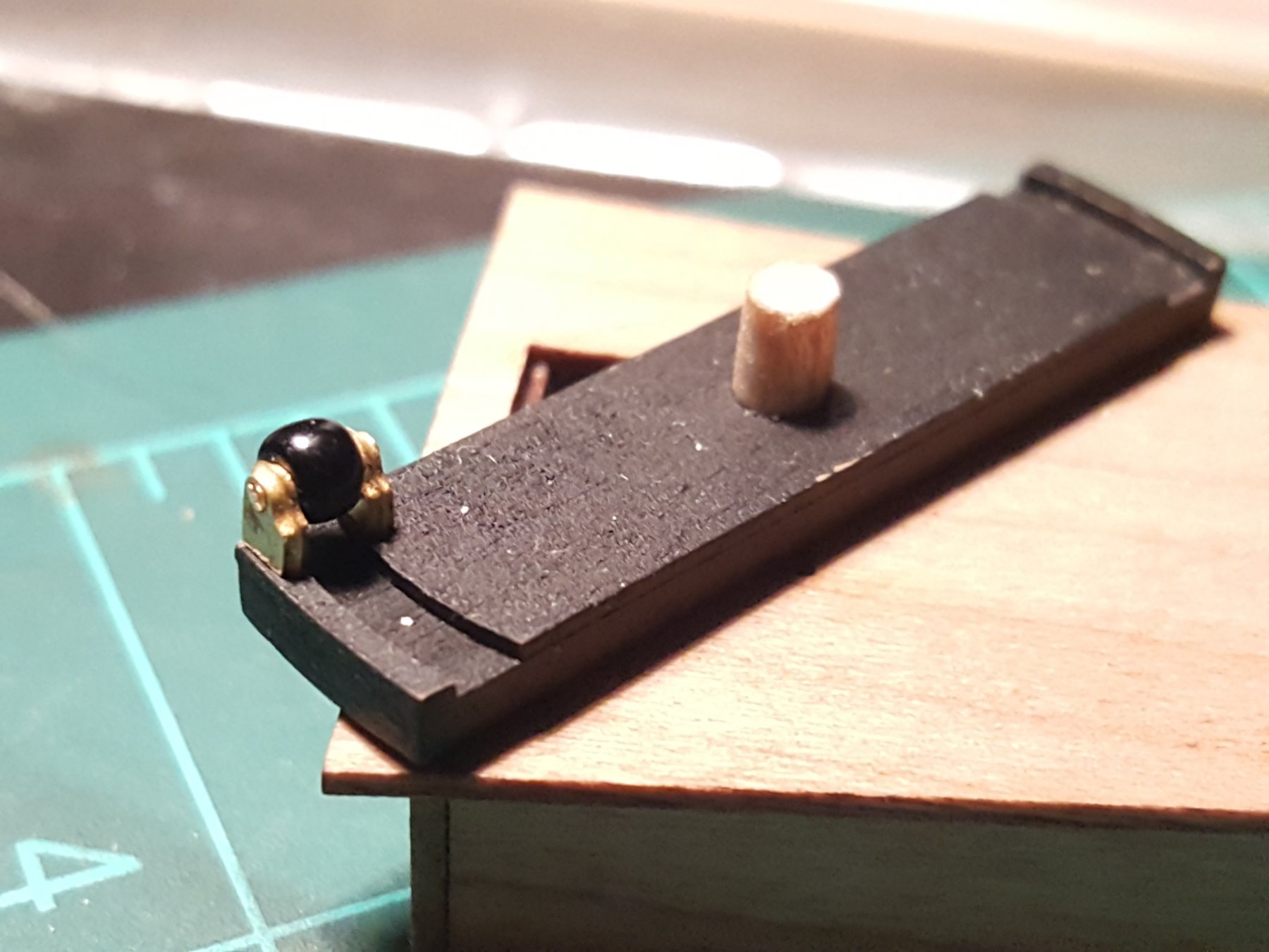
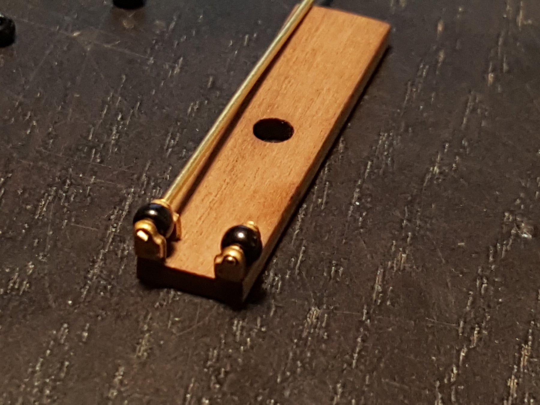
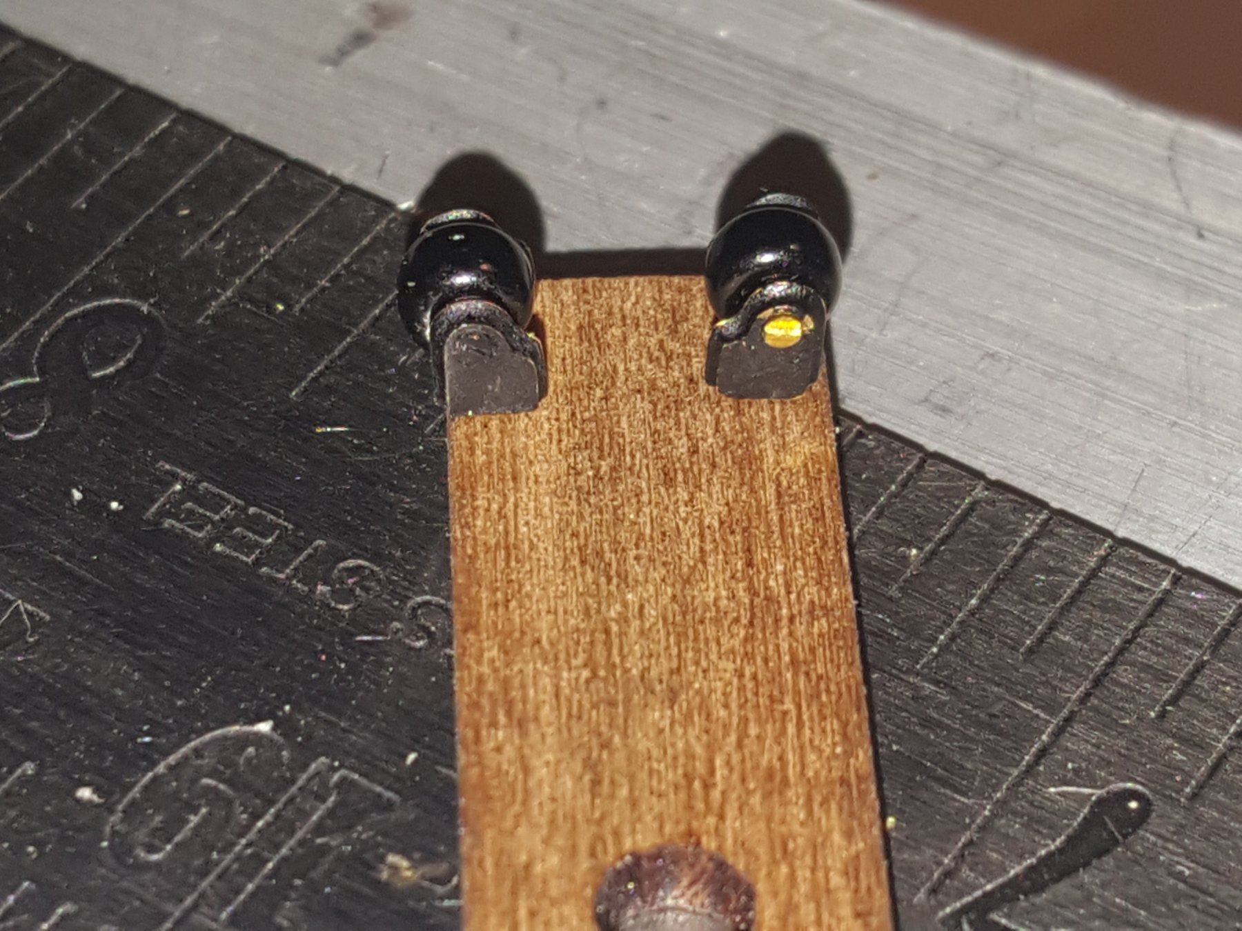
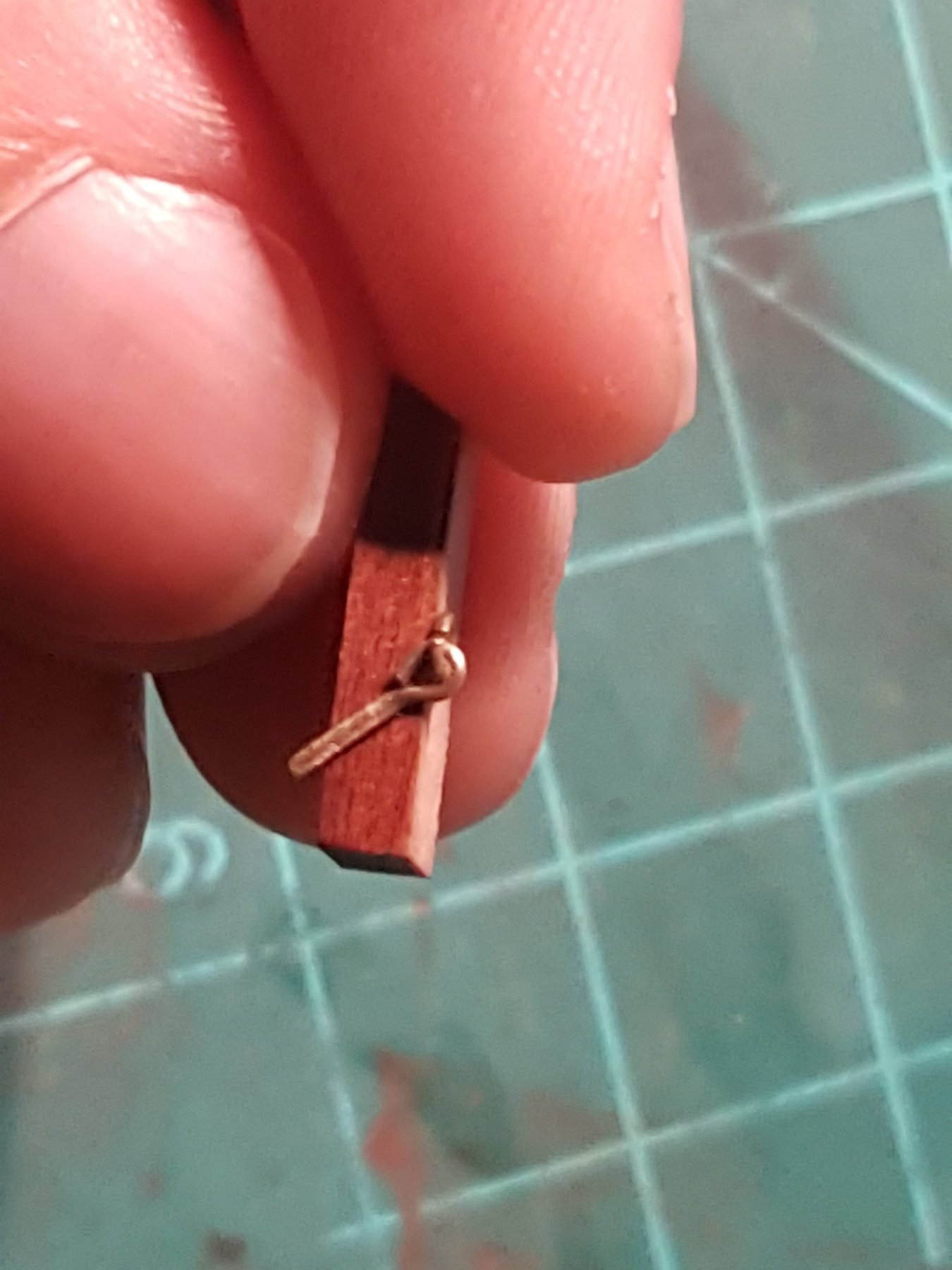
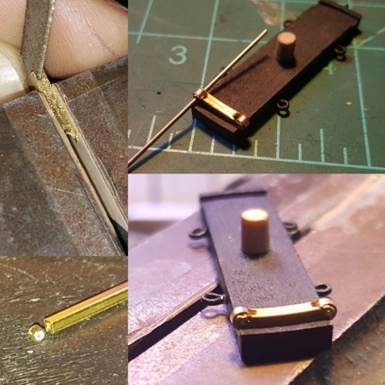
Hi everyone, so been working on the wheel and this is pretty much what I came up with. I took a bent square brass tube 1/6" and filed the ends down and added the crimp bead wheels. It feels really well and was pretty easy to make. The wheels actually do spin.
- 362 replies
-
- 10
-
-
- active
- revenue cutter
- (and 1 more)
-
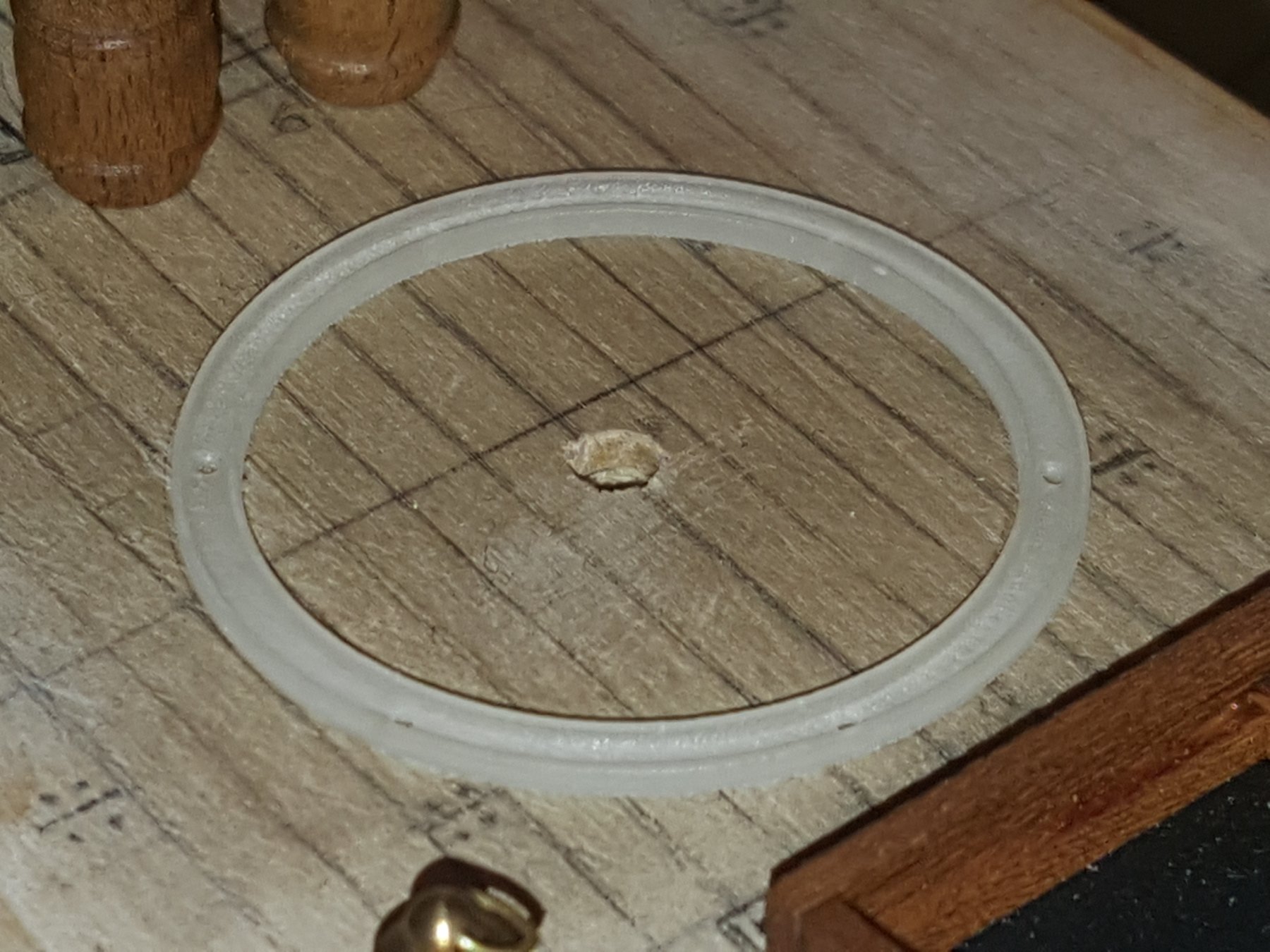
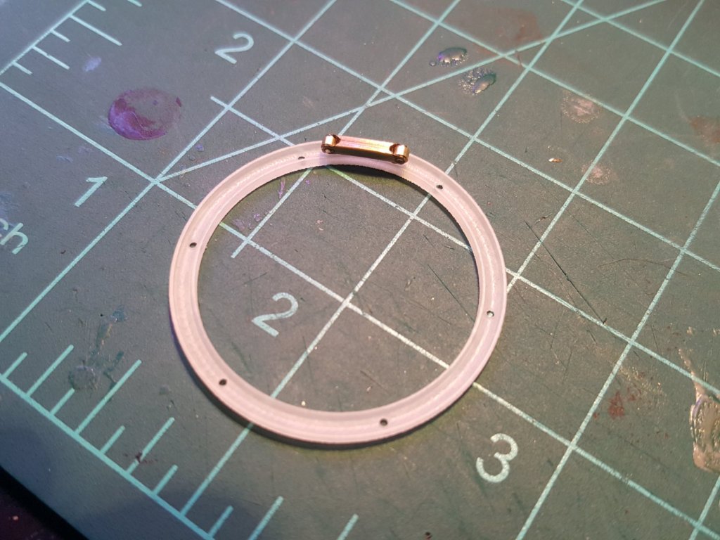
And here we have the completes pivot ring fresh from shapeways. Looks just as it needs to look I am very pleased. I am always excited when faced with a puzzle how the end result turns out out gives me confidence in my abilities in my work. Now regarding attaching the wheels in a manner not too technically crazy...

- 362 replies
-
- 4
-
-
- active
- revenue cutter
- (and 1 more)
-
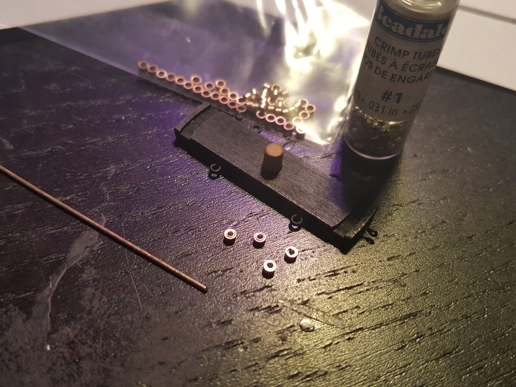
So here is the final pivot wheel which will be arriving from stairways in a few different materials by early Feburary. Next I made new wheels they are crimp beads 2mm by 1mm wide with silver 1x1mm beads shoved inside. So much smaller than before now just thinking of an axle to put them on.... hmm


- 362 replies
-
- 3
-
-
- active
- revenue cutter
- (and 1 more)
-
Thanks Mark! I'll post some pics of how I built the template in a bit. And Richard that's exactly what I needed. I'm honestly now trying to contemplate how to make such a jig with my carriage. Thinking of taking a chainplate and bending it to shape? That said I am familiar with the Dallas kit the ring size is much larger which is part of the problem. This ring is literally 30mm in diameter with the carriage 35 by 7mm. So the parts are extremely tiny and i'm using what is available or what I can create. I ordered some brass crimp beads at 2mm by 1mm maybe those will work with a bit of tweaking but already I'm much happier with this design thank you so much for showing me your approach.
- 362 replies
-
- 2
-
-
- active
- revenue cutter
- (and 1 more)
-
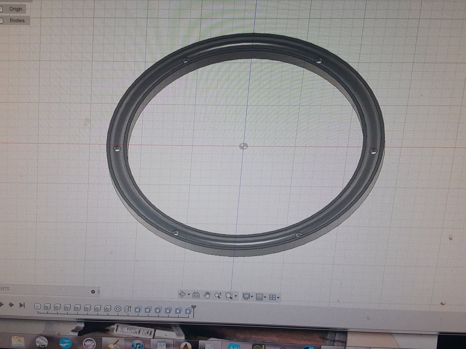
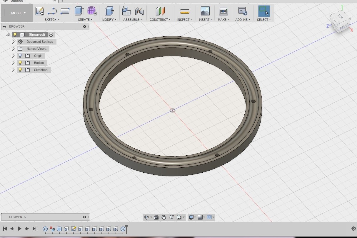
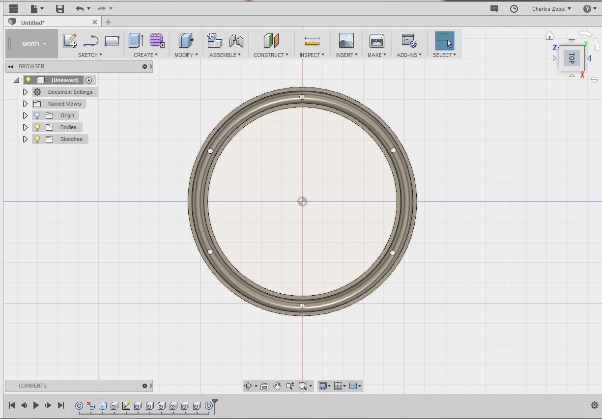
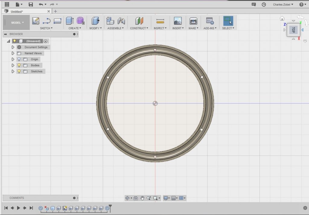
Just another update I have also been practicing 3d printing via fusion 360. While the dimensions may be a bit off creating the pivot ring using this method was super easy. While I don't have a printer if anyone is familiar with shapeways you can send any file you make and they will make it for you in a series of different materials then ship it to you at a reasonable price. This was so easy I may go with this method at least for the top part of the ring and glue it to the lower wooden piece.

- 362 replies
-
- 7
-
-
- active
- revenue cutter
- (and 1 more)
-
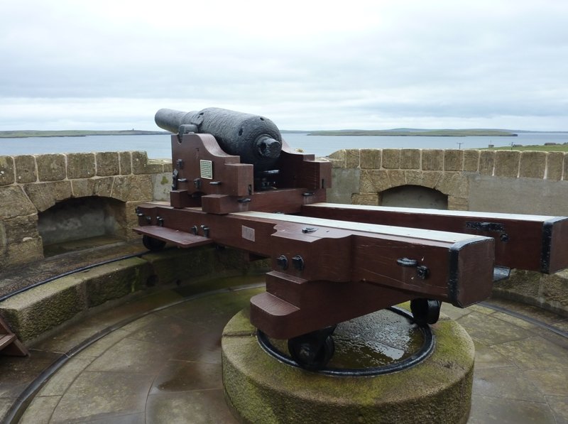
Hi Eric, yes Dan (Shipmodel) knows his stuff! The main issue I have is with the wheels, should I try smaller wheels maybe made from brass? And Mark yes I agree there are all sorts of ways to achieve a nice looking result in ship modeling. And just the same it seems there were just as many variations to sailing ship deck fittings as one can imagine. Ive seen all sorts of carronade carriages that serve the same function but vary in minor detailing, placement of deadeyes, height, etc. so really it's not like building a WWII ship where one can look up a mark whatever gun type and boom there ya go. But that is part of the fun isn't it? Using ones imagination to create an educated guess to make your ship model look like she probably did in real life. Take into account the changes that a wooden warship would go through in it's lifetime upgrades in tech and changes to the overall building profile and the sky is the limit. For my ship "the Active" I imagine she retained the low bulkheads and toe railing as per the Doughty plan, the carriage likely was raised over time. The "high pivot" design came about in the 1820's/30's (check the pic of Fair Rosamund below) then evolved into the more complicated pivot types via the civil war era using the Dahlgren guns and those half circle type platforms that ships like Constellation and Kearsarge used. Also since I plan on building all 3 cutters, I want each to represent a different level of development meaning the Active will have 1 pivot (maybe some swivels) with a toe rail, the Monroe 52 ton will have a low rail with stanchions and the Vilgilent 80 tons with full bulwarks and cannon looking like a precursor to the Morris/Taney class. This is just my guess these ships probably rolled off the assembly line as needed and with each passing year there were more variations from the original Doughty draught's. So the period from Active launched or purchased in 1816 to Vigilant launched in 1824 means I can approach each model a bit differently.
- 362 replies
-
- 5
-
-
- active
- revenue cutter
- (and 1 more)
-
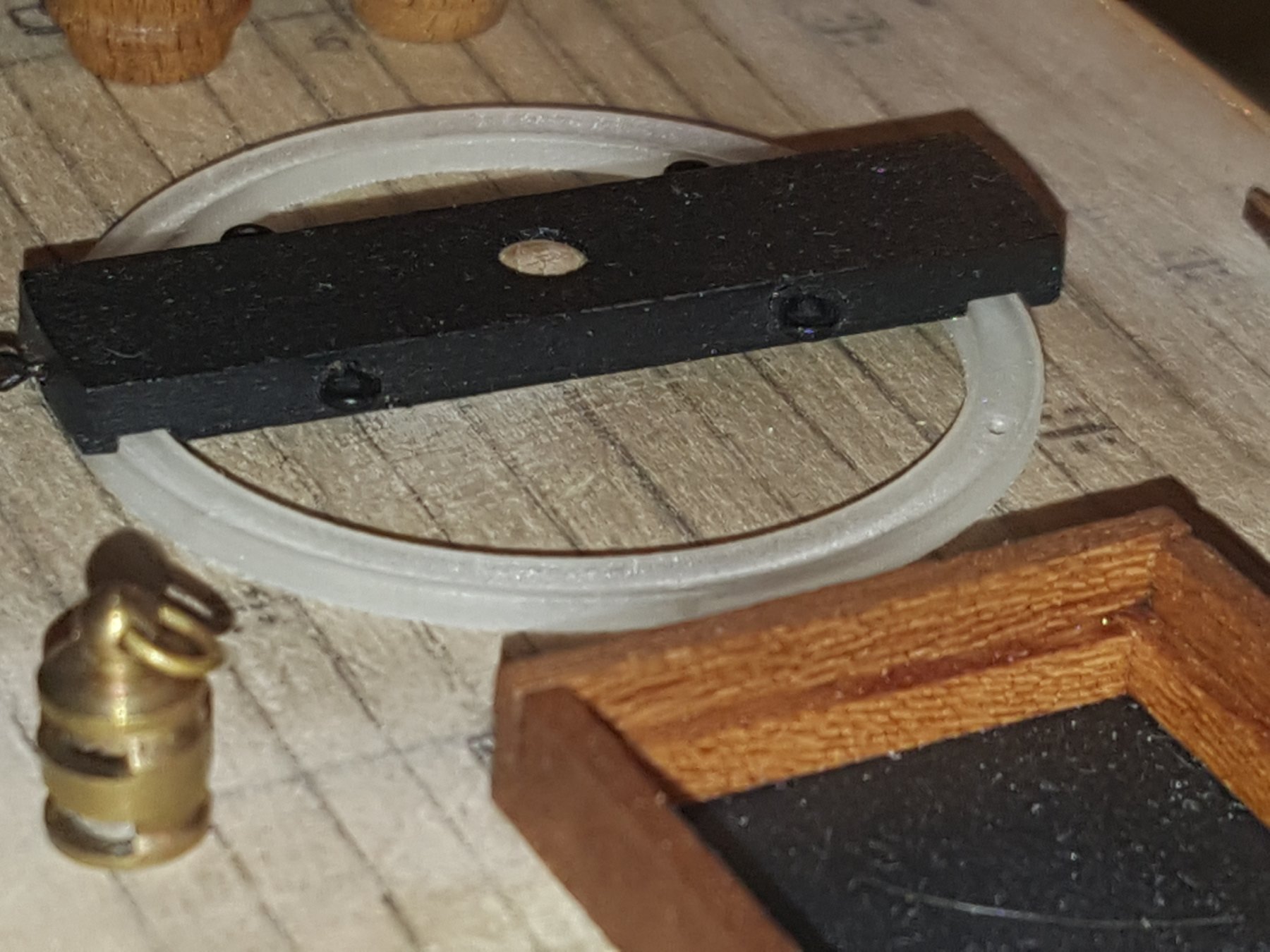
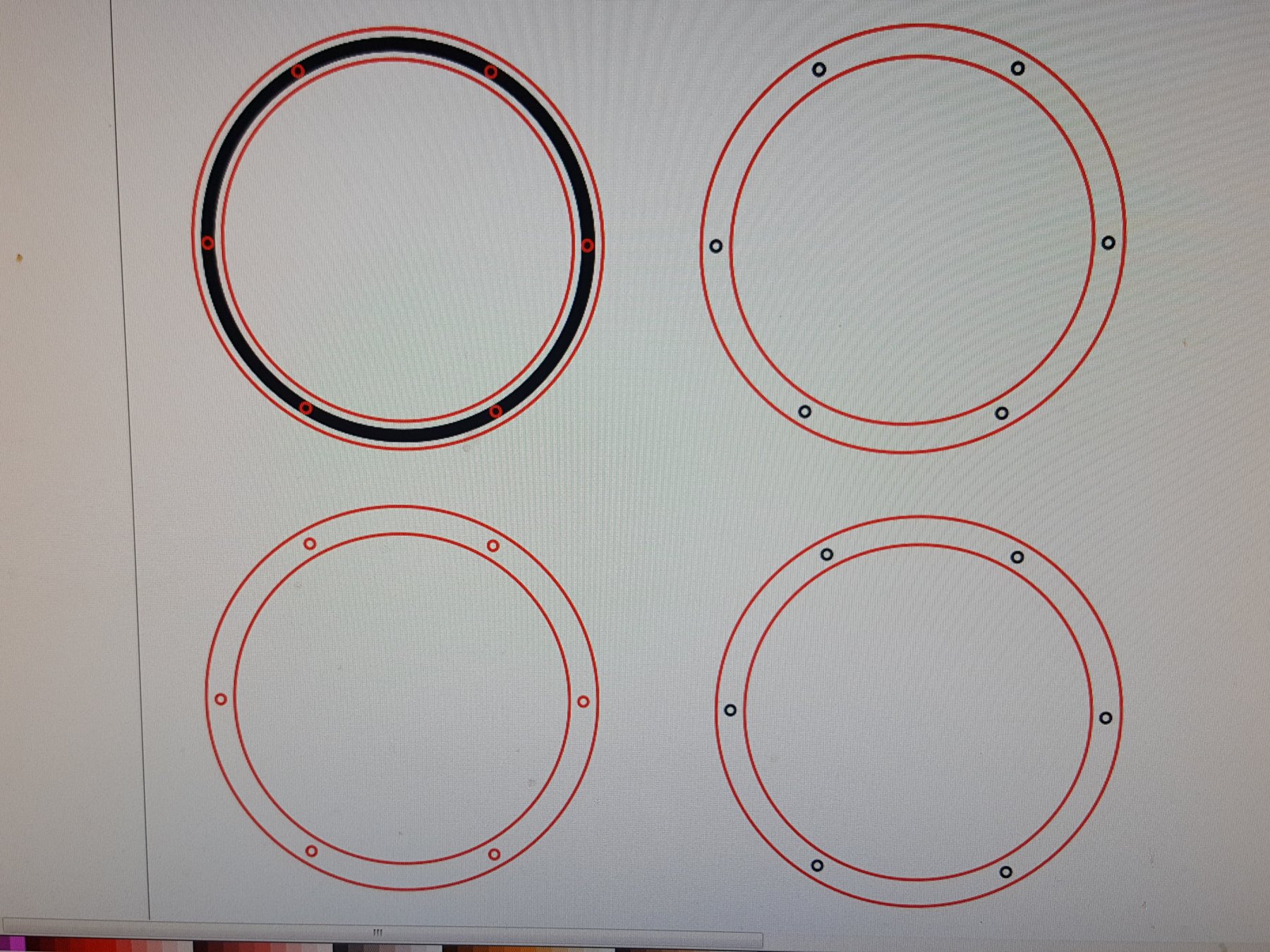
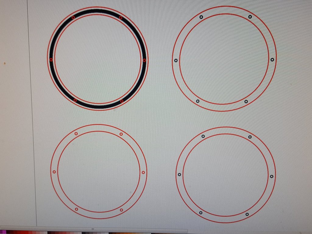
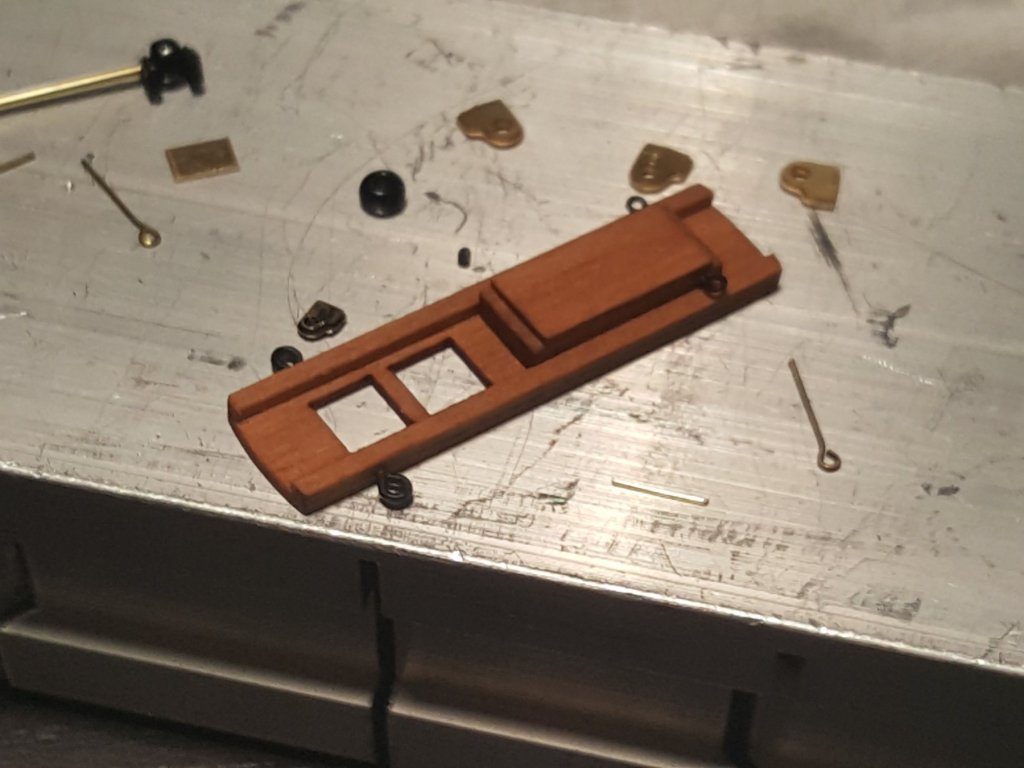
And here is a closer look of the ring template. The right side will be wood the red line is cut while the black etched so I know where the bolts go. The left side has two variations. The bottom will be a flat piece in plastic painted black and stacked on top. The top has a black etch line and the laser will then etch a groove into the piece then cut the bolts out. So the laser will make the bevel and I can avoid having to Dremel it out myself. ;) I'll probably make the bolts out of toothpick material and will pick the rings which ultimately look best.
- 362 replies
-
- 5
-
-
- active
- revenue cutter
- (and 1 more)
-
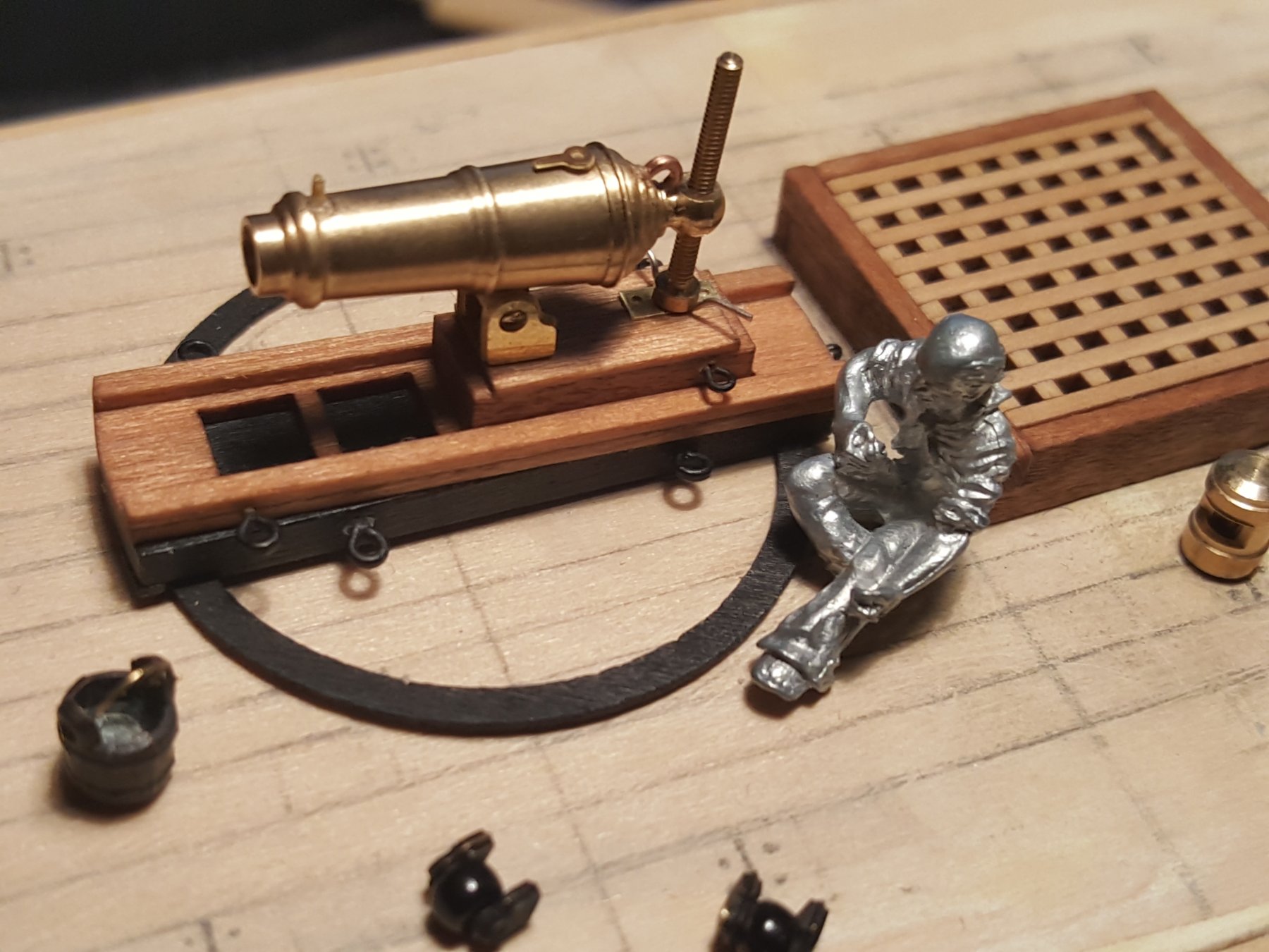
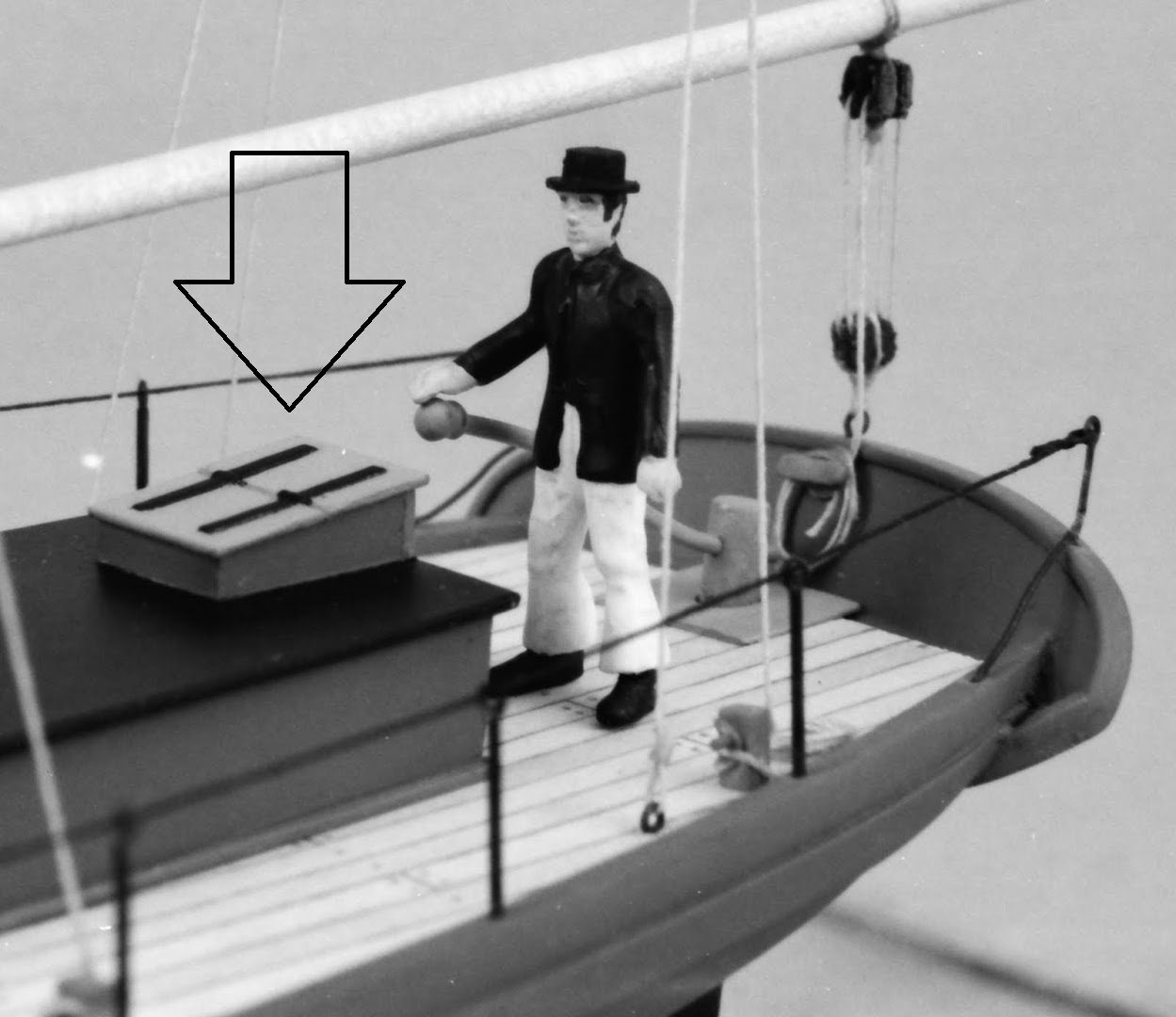
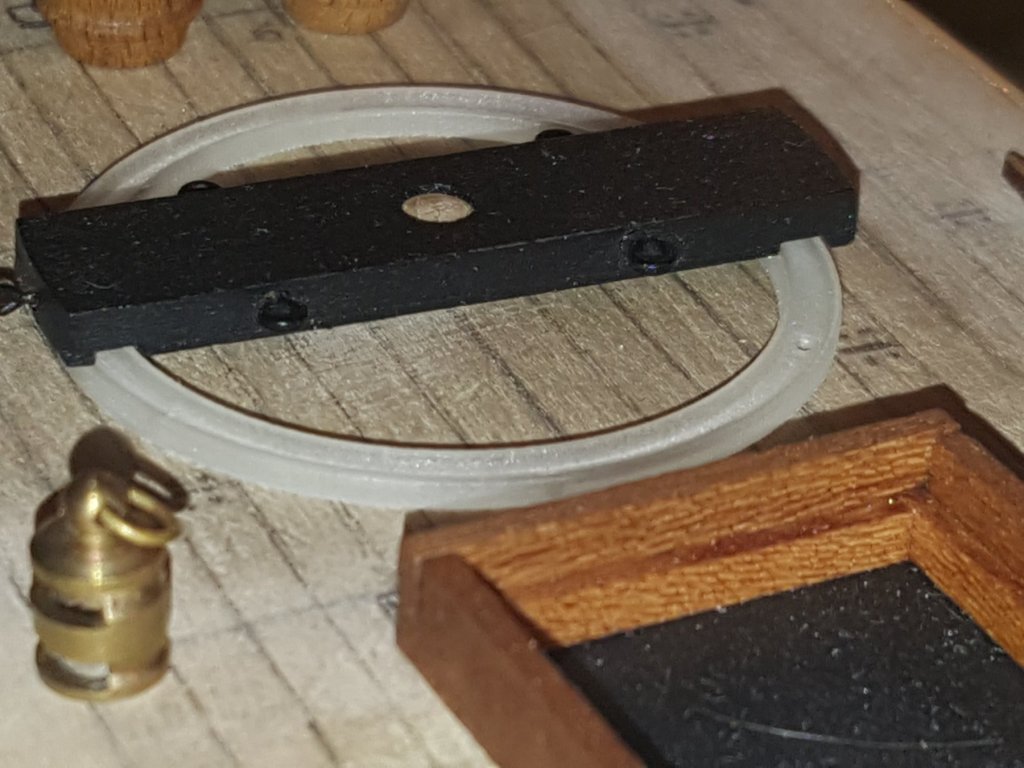
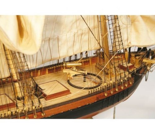
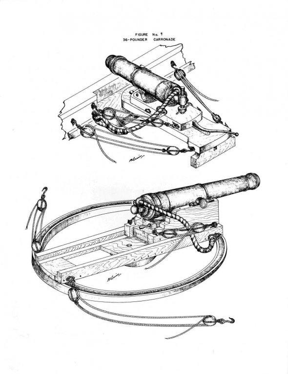
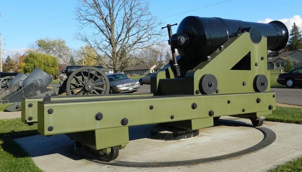
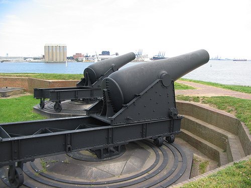
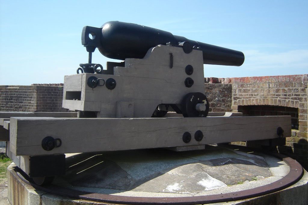
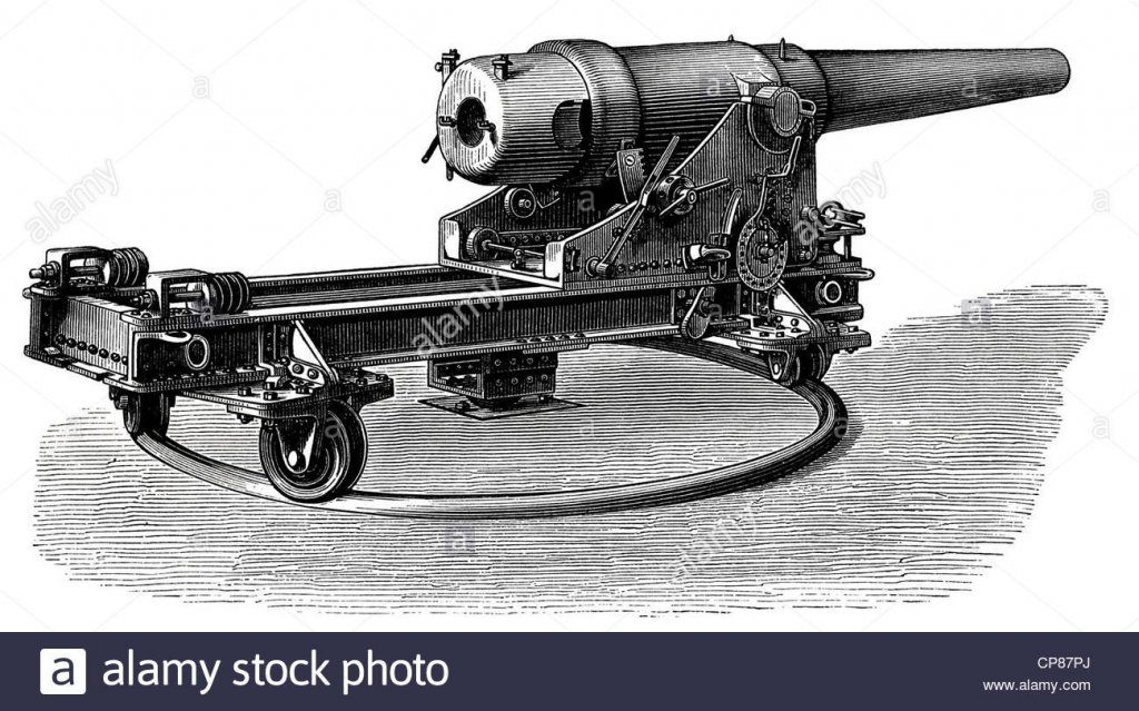
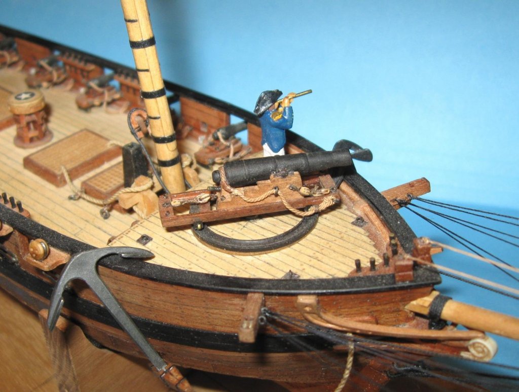
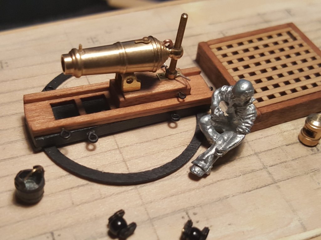
So here is where I get confused. Chapelle describes the ring as being scooped on the inside and the wheel I imagine slides in that groove. In the image I posted from nrj you can see an example. That said I don't see in this pic where the wheel could be? Dan (Parisier) showed me his Oneida carronade pictured below which has a logical looking mount (the image with the little wooden man). That would make my wheels too big and I could change them however it's not easy to find many items much smaller. Now I see very often another design where the pivot ring is flat and bolted while the wheels are beveled. While I know many of the canons I pictured are from a much later period the idea seems to be the same. Also the Bluejacket kit suggests that this type of mount was used and has a ring with bolts and I have made a new laser template to show them. The bolts will likely be wood color while the ring stays black. The ring now needs to be either metal or plastic not wood so headed to the laser shop this week. Other ship models like Fair Rosemund or civil war era ships have pivot cannons or similar mount. So yeah I could do this approach instead and it would make the carronade higher which I kinda like I am just hoping I am following a design that looks reasonably historically accurate. If anyone has some images of pivot cannons/carronades they may want to share or has suggestions feel free it could be helpful.
- 362 replies
-
- 7
-
-
- active
- revenue cutter
- (and 1 more)
-
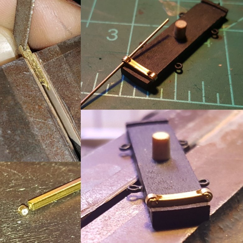
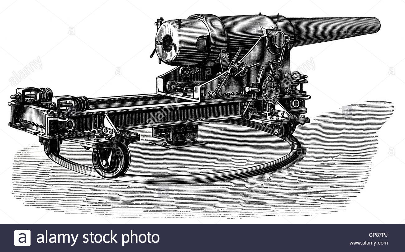
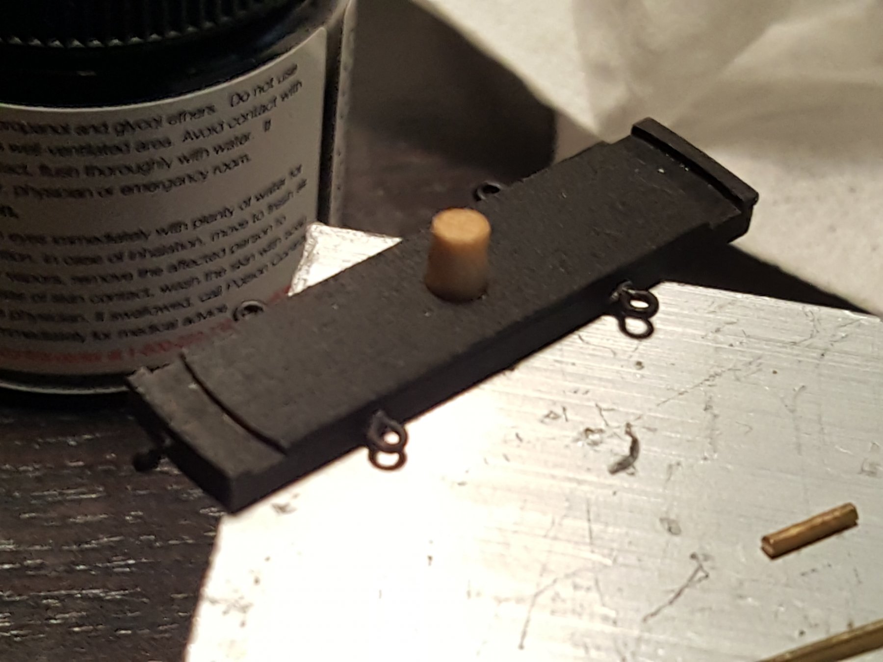
So here the issue, I realize that the pivot ring and carriage are supposed to slide so the carronade can be rotated on deck and from what I see there were some sort of wheels under the carriage. Ship models of these ships like Alert or Ranger don't show wheels but they should be there, so I decided to make my own, however I am striving for accuracy yet also don't want to drive myself too crazy. I ultimately opted for tiny beads 2mm in size which on the finish piece spin along that groove I made. I tried other options for wheels but everything was either too wide or too long (this is of course a very small model). :P The braces are actually from the caldercraft 12lp carronade kit which looked perfect and were the right size I cut brass wire to make the axle.


- 362 replies
-
- 6
-
-
- active
- revenue cutter
- (and 1 more)
-
Hi everyone! So about time I did an update, mainly have been waiting on a shipment of carronade parts so decided to take a small break. That said I have been tinkering away quite a bit on metal work for the carronade. It's been a new learning curve metal acts differently than wood. Overall you can see the various rings I added and also the detailing added to the carronade itself, breech ring, loading, aim, etc. I wanted to finish the carronade before I posted but noted a snag I'm hoping some of you might help me out with. It's regarding the carriage wheels.... BTW I just love that little bucket, it's darling!


- 362 replies
-
- 9
-
-
- active
- revenue cutter
- (and 1 more)
-
The subsciption frigate New York and other details
CharlieZardoz replied to CharlieZardoz's topic in Nautical/Naval History
7 makes sense I am assuming all or most of the subscription frigates had 7 windows which those who survived long enough had the outer two planked over to 5. That said the arrangement on that stern makes sense I imagine she looked more or less in that fashion.- 51 replies
-
- 2
-
-
- frigate
- subscription
- (and 1 more)
-
The subsciption frigate New York and other details
CharlieZardoz replied to CharlieZardoz's topic in Nautical/Naval History
Very nice stern depictions. I'm wondering is there any evidence which states philadelphia had 6 stern windows as opposed to 5?- 51 replies
-
- 2
-
-
- frigate
- subscription
- (and 1 more)
-
American sailing warships with no plans or records
CharlieZardoz replied to CharlieZardoz's topic in Nautical/Naval History
So how does Macedonian relate to Congress then since she was built right before. The later Congress of course.- 401 replies
-
- 2
-
-
- John Adams
- Alliance
- (and 3 more)
-
A first look at the Frigate John Adams, 1799-1829
CharlieZardoz replied to Talos's topic in Nautical/Naval History
Well guys from what I read most of these ships were considered slow and had poor serviceability. They were ultimately a placeholder before the better subscription frigates and schooner/brig/sloops took over. A hodgepodge navy of strange ships that were ineffective so I doubt they wasted too much time trying to modify them. -
A first look at the Frigate John Adams, 1799-1829
CharlieZardoz replied to Talos's topic in Nautical/Naval History
I suspect she was a purchase and then the upper works would have probably been closed up and she would have looked more like a proper sloop. That is for the 2+ years she was in service -
A first look at the Frigate John Adams, 1799-1829
CharlieZardoz replied to Talos's topic in Nautical/Naval History
And here is Maryland/Patapsco. I imagine many of the smaller ships we lack plans for looked somewhat like these but as to their unique variations I wouldn't know where to begin.
-
A first look at the Frigate John Adams, 1799-1829
CharlieZardoz replied to Talos's topic in Nautical/Naval History
Hi all! Just for fun I thought I'd add the plan in question.
-
Ah I meant rudder (corrected) was late when I posted very sleepy And yes John thank you. In reality im only building one atm the others are mere skeletons at this point which getting them started is easy its all the detailing which is the real work of shipmodeling so many little things
- 362 replies
-
- 2
-
-
- active
- revenue cutter
- (and 1 more)
-
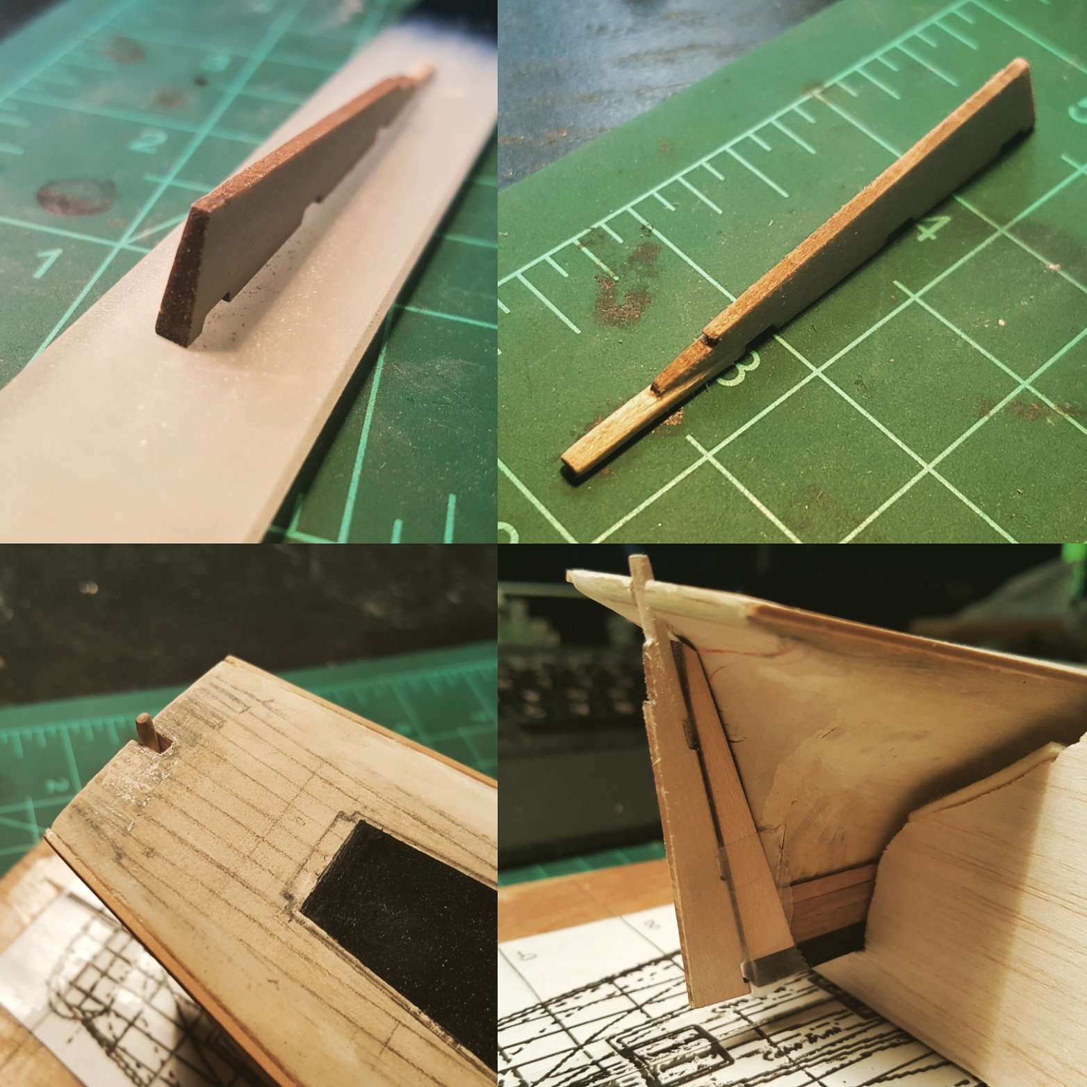
Today I shaped and sanded a test rudder. The shape looks about right but want to work on accuracy ie. a tool to sand on an angle and making the upper part perfectly round. But overall a nice first attempt.

- 362 replies
-
- 6
-
-
- active
- revenue cutter
- (and 1 more)
-
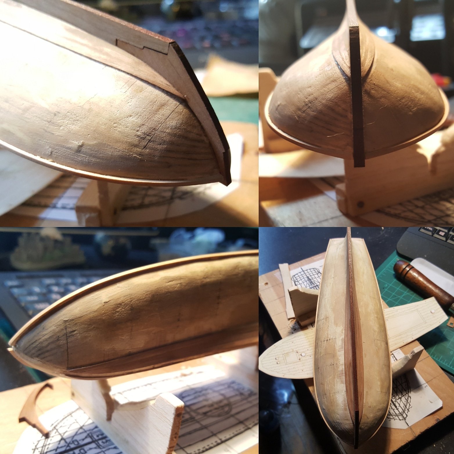
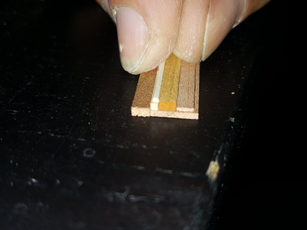
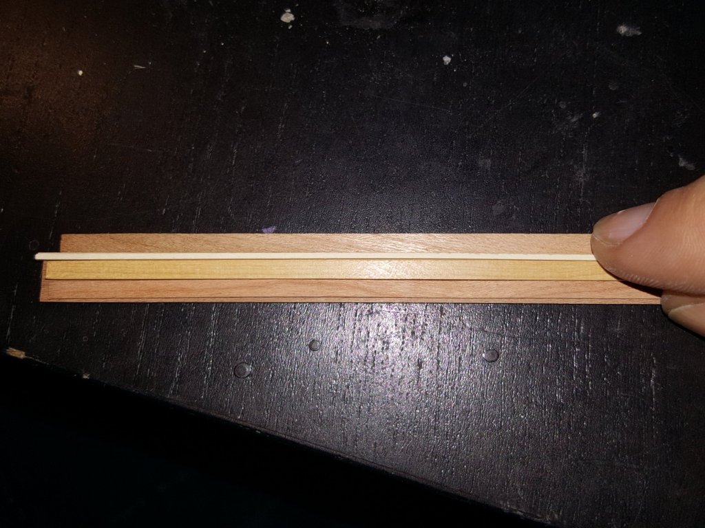
Hi all! A quick progress report im realizing it's time to fully plank the hull. Otherwise I cant add anything onto the deck so getting over my fears and getting it done. Here it is so far. The lower part will be coppered so not much detailing needed. The top strip is the first piece of the wale a 1/64 by 1/64" strip of boxwood. If you look at the pics you'll see my plan on how the wale will look. Basically its a 1/8 by 1/16 boxwood strip with a holly 1/32 by 1/32 above it. The wale itself will probably be painted black with the upper works left boxwood color and the lower cherry colored. I chose boxwood for the wale because I wanted a less grainy type of wood to make the wale stand out a bit more. The design for the wale is my interpretation of the AL Dallas plan pictured below.

- 362 replies
-
- 5
-
-
- active
- revenue cutter
- (and 1 more)
-
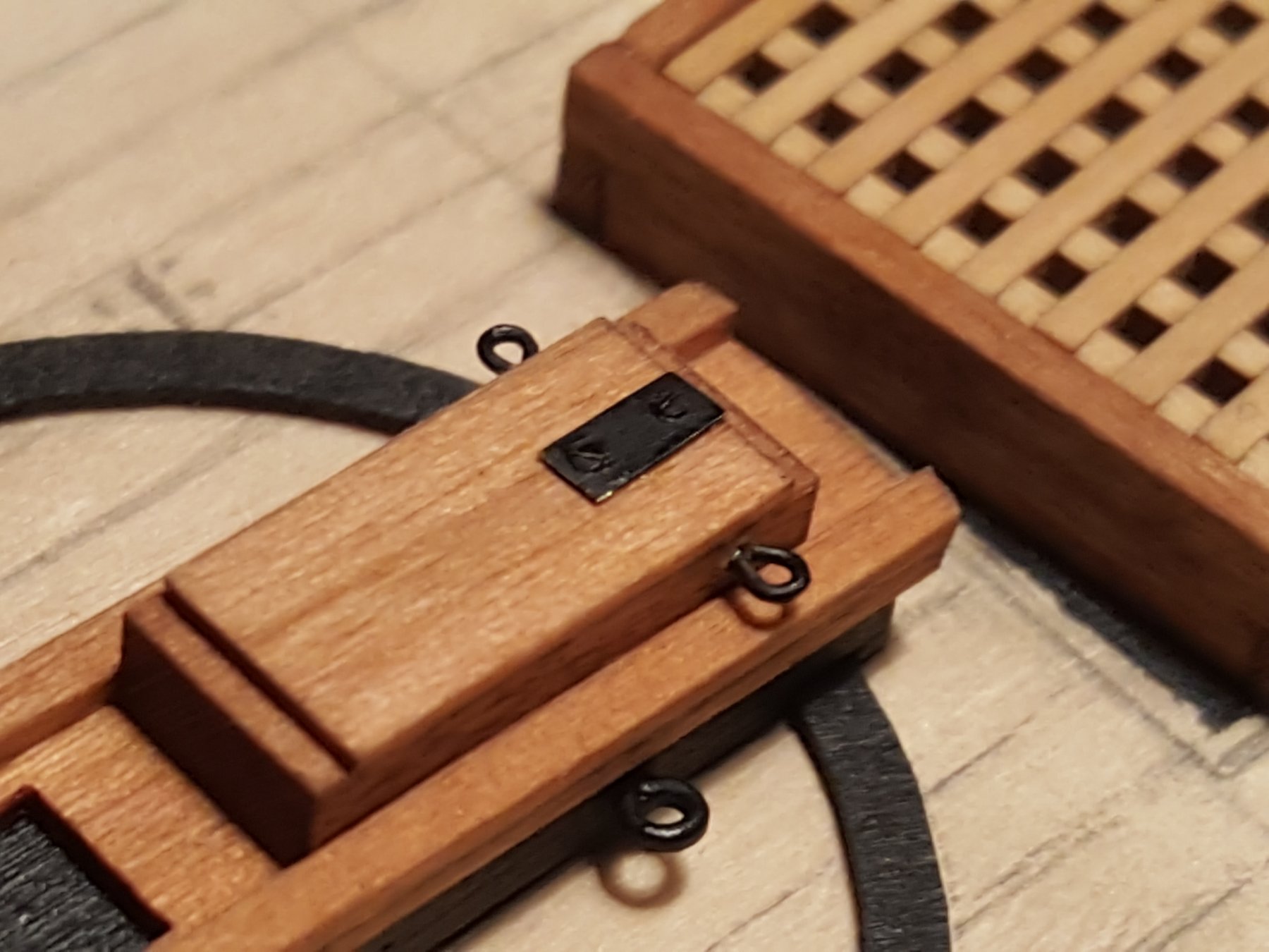
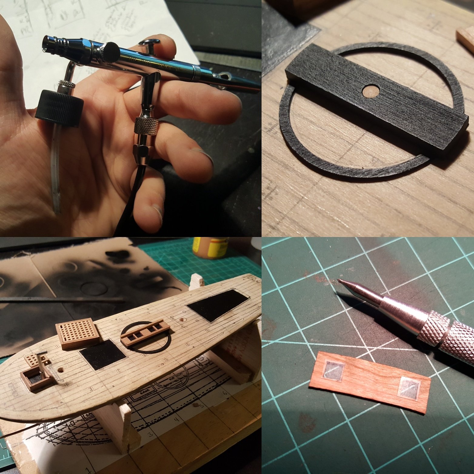
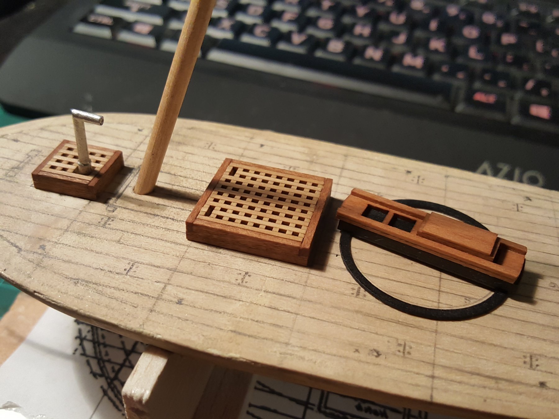
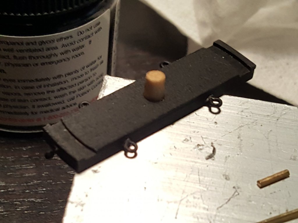
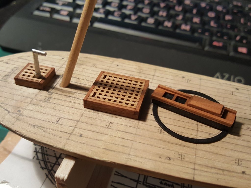
Hi everyone! Here is just a quick update in addition to painting the negative space for the hatches black I painted the lower part of the cannon carriage. I tried using a brush but the strokes were killing my ocd so figured itd be good practice for my airbrush skills and anything that didnt look good would be covered anyways ;). The vallejo paints when thinned out looked pretty nice. I also used a carbide scribe on a microscope slide so I can make little windows for the cabin. Last I stained the hatches and carriage so the have a finished look now.

- 362 replies
-
- 9
-
-
- active
- revenue cutter
- (and 1 more)
-
Hi yes thats pretty much the plan. Im going to try in 28 guage brass first and if that is too cumbersome will try plastic
- 31 replies
-
- 1
-
-
- ventilator
- flue
- (and 4 more)
-
That's pretty unbelievable tbf. I miss hobbymill... sniffle
-
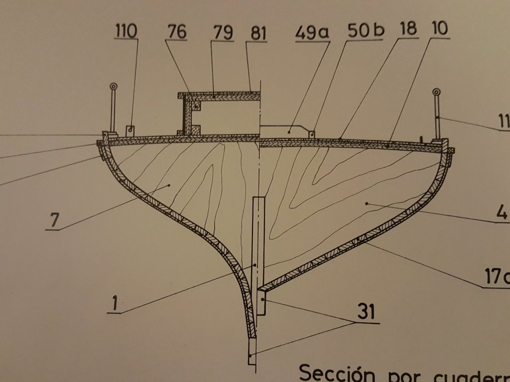
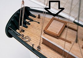
Yes Dan exactly! The model "plans" show the companionway hatch to look flat or let's say level to the deck house. But since the ship is small I figured it should be a bit slanted upward just like the model you showed above and the black and white image below. I'd actually like to make the hinges work if possible lets discuss at our next meeting.

- 362 replies
-
- 5
-
-
- active
- revenue cutter
- (and 1 more)