ccoyle
-
Posts
8,612 -
Joined
-
Last visited
Content Type
Profiles
Forums
Gallery
Events
Everything posted by ccoyle
-

Intro to Card Models Part VI: Building V108 - The Superstructure
ccoyle replied to ccoyle's topic in Card and Paper Models
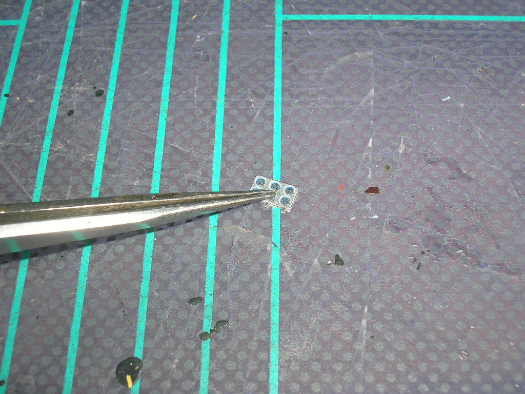
I thought about using PVA glue, but I wasn't sure if it would dry hard enough. I applied the top coat from the inside mainly because a) the applicator brush was too large to keep everything entirely within the frames, and b ) I didn't want to see what would happen if I tried to wipe off any excess on the printed side of the part. As with any medium, there's usually more than one way to do these various tasks with card, so thanks for sharing alternative methods. With regards to very small parts, especially these detail parts that are many times smaller than a fingertip, it pays to handle them as much as possible with tools, such as tweezers, instead of fingers. I even use my knife tip for picking up small parts from my cutting mat - a light stab to pick up the part doesn't leave a visible mark on the printed surface. Cheers! -
Intro to Card Models Part VI: Building V108 - The Superstructure
ccoyle replied to ccoyle's topic in Card and Paper Models
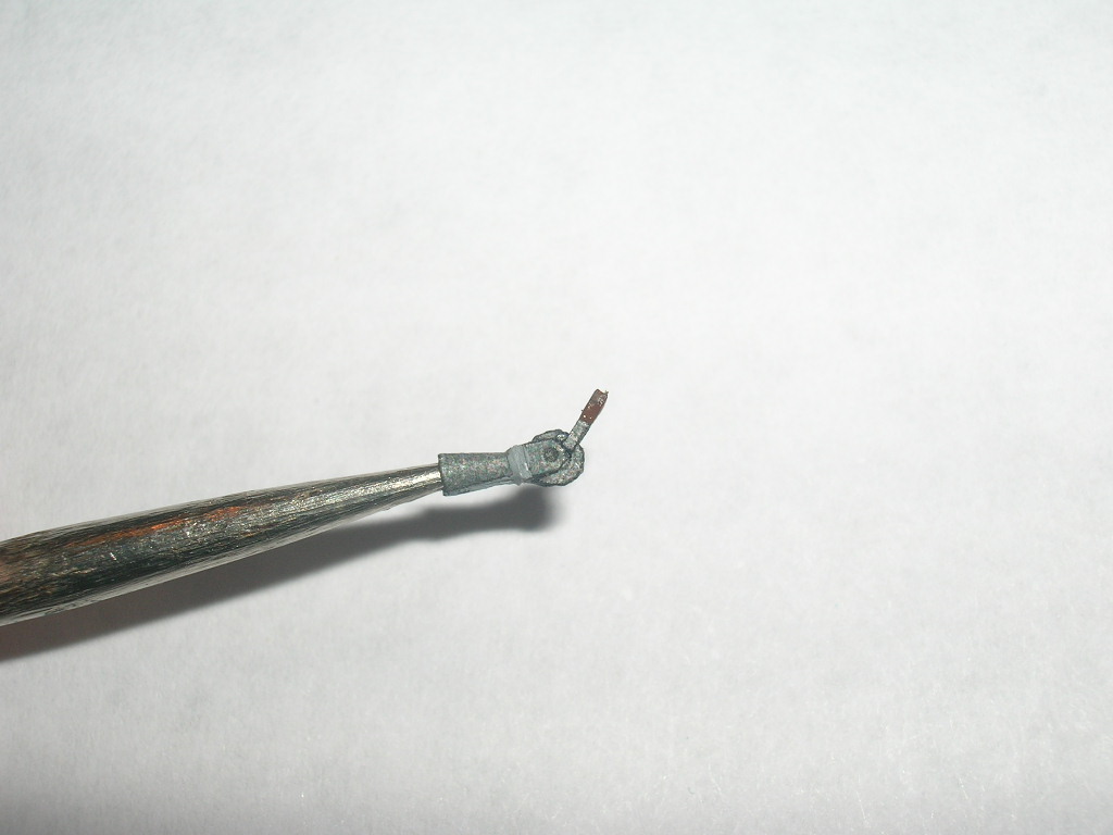
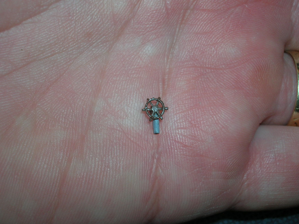
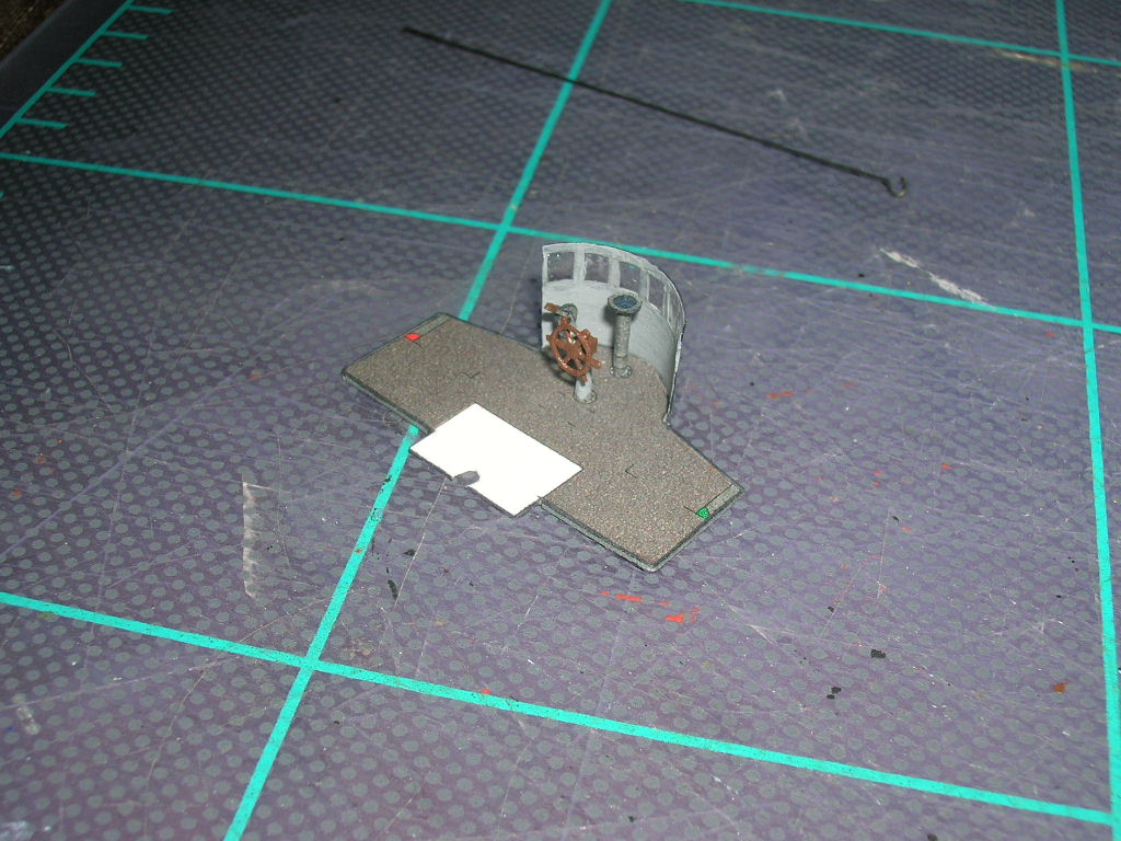
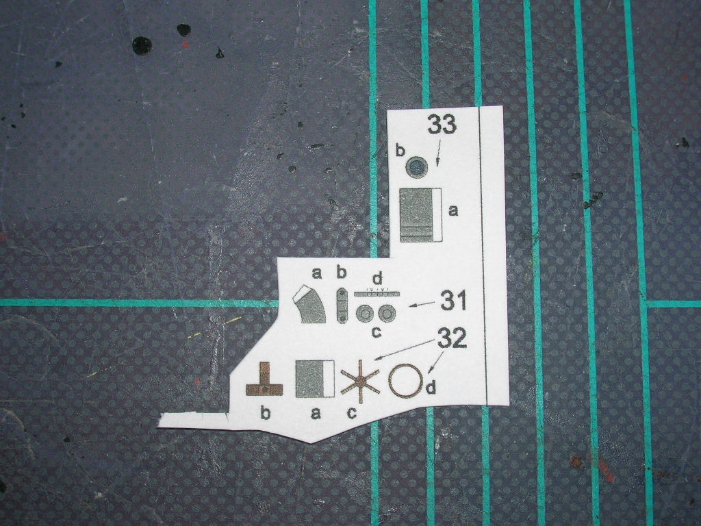
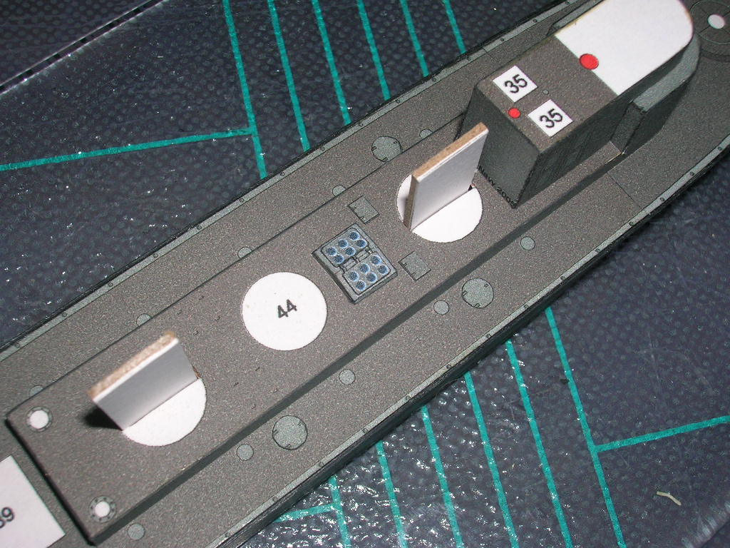
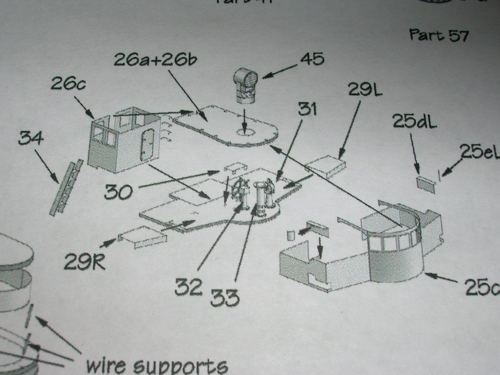
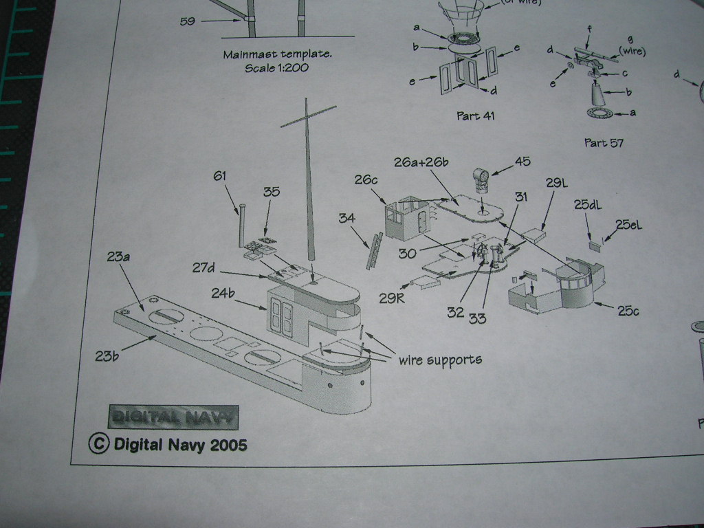
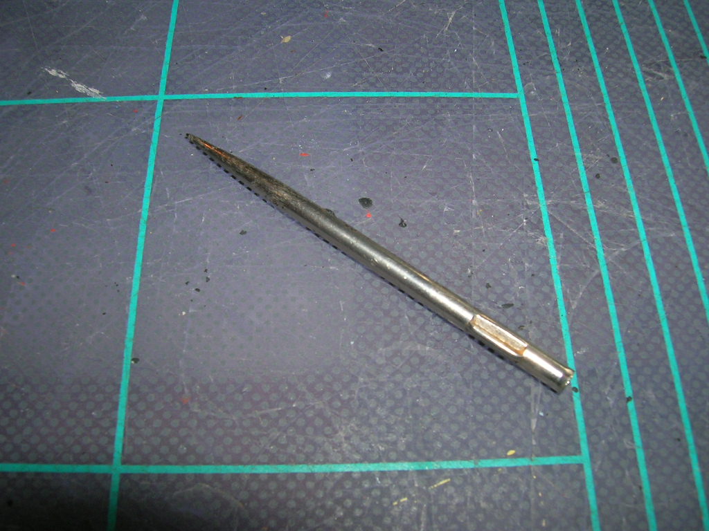
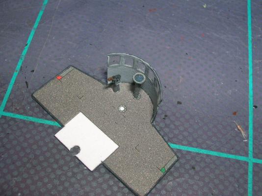
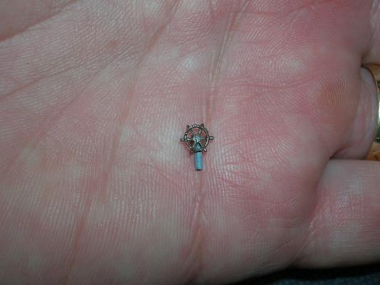
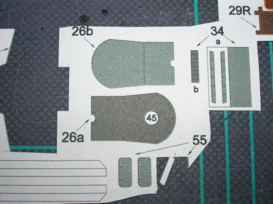
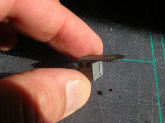
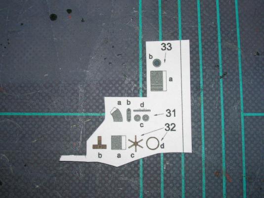
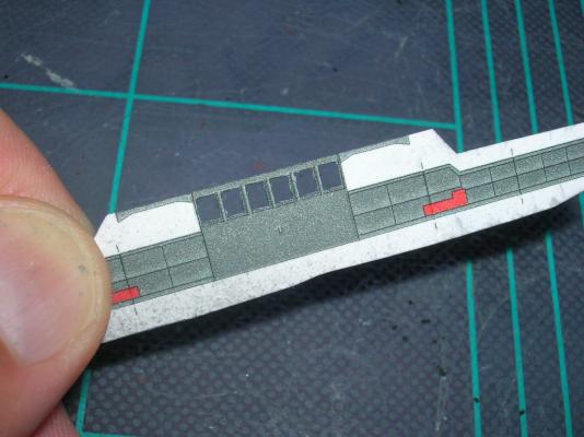
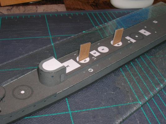
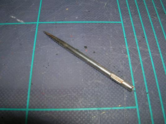
Next up is the engine room telegraph, consisting of the base (31a), mounting bracket (31b), telegraph (31c), and telegraph handle (31d). The base, 31a, presents a new challenge, since it is a tiny cone, not a tiny cylinder. Rolling a cone is much easier if you have something conical to form it with. The tip of my scribing tool is perfect for this job. In all other respects, rolling a cone is the same as rolling a cylinder. The mounting bracket has fold lines; on such a small part, the usual scoring and folding process doesn't work very well. I recommend using your knife tip to cut through the top layer of paper fibers only, then complete the bends. The two parts 31c go back-to-back to make the telegraph; when this is done, glue the telegraph into its bracket. The handle, 31d, also has fold lines, but don't bother with them. Glue one side of the handle to one side of the telegraph, then bend the handle over to the other side of the telegraph and attach it. Dab a little glue to the inside of the handle and then crimp it closed with tweezers. Personally, I think the handle should be wood, so I painted it brown. Glue the finished telegraph to its base and glue the base to the proper spot on the bridge. Last up is the ship's wheel. Cut, roll, and glue the stand (32a) in the same manner as for the compass stand. The wheel housing (32b) is a tiny box; give its fold lines the knife-tip treatment, then fold up and glue the sides. Attach the housing to the stand. The wheel spokes (32c) and ring (32d) require some careful cutting. Remember to cut away from the wheel hub. Cut the inside of 32d first, then cut the ring from the parts sheet; glue the ring to the spokes, then glue the completed wheel to the housing. Don't worry about edge coloring parts 32 b-d before gluing - the finished wheel and housing can be painted brown once everything is glued together. Glue the finished wheel assembly to the bridge deck. Now we can add the bridge roof (26a and 26b) and radio room (26c). The radio room has printed windows, but there are no parts for detailing the radio room interior, so we're going to let the windows be. There's a spot on the radio room wall to add a hatch (part 55 - hinges to the left). Use contact cement to glue the roof (26a) and roof interior (26b) together. Score, cut, and fold the radio room (26c) and attach it to the roof one wall at a time. There will be a gap in the aft wall where it meets the foremast. The roof/radio room assembly can then be mated to the bridge assembly. Afterwards, you can add the two pices of entryway fascia port and starboard (these were originally part of 25c if you did the modified construction; they'll still be attached if you've used the unmodified 25c). Not-quite-finished bridge should so far look like this: Now, sit back and admire your work for a bit. Next we'll add the bridge wing details.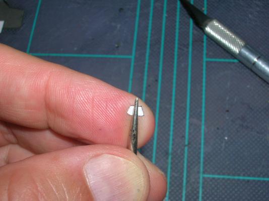

-
Intro to Card Models Part VI: Building V108 - The Superstructure
ccoyle replied to ccoyle's topic in Card and Paper Models
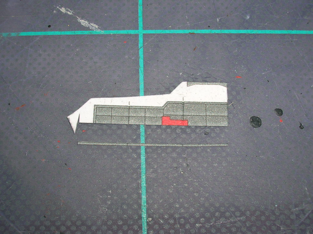
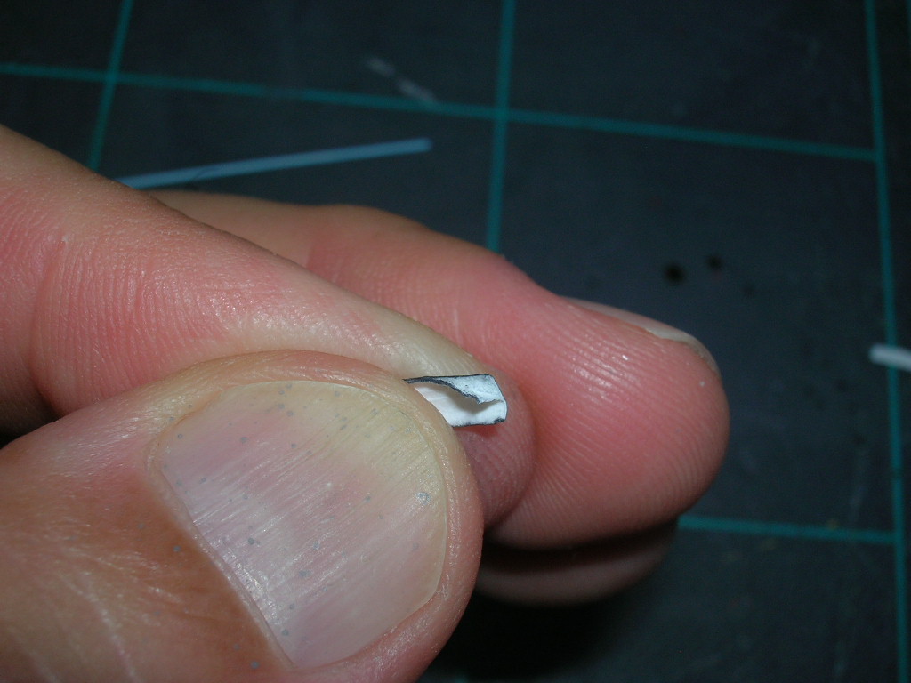
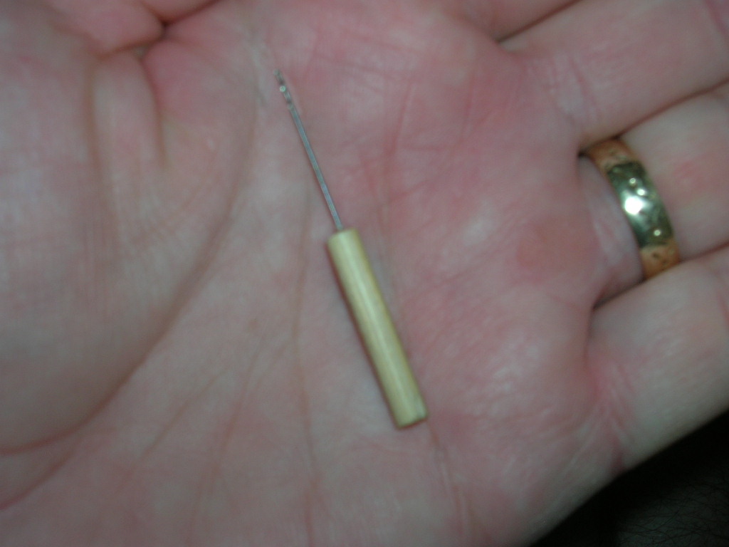
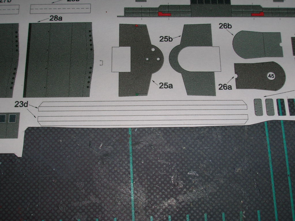
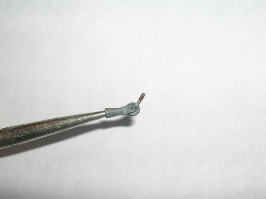
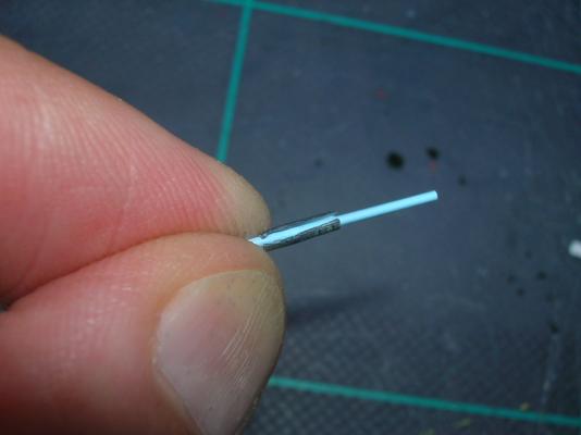
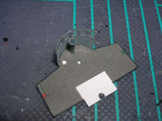
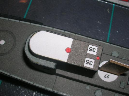
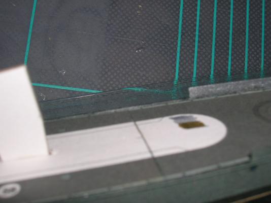
At this point, if you set the bridge assembly atop the conning tower, you'll notice that the radio room floor partially covers the locator for the foremast (the red spot). We'll need to fix this before going further. Either carefully cut or drill out the foremast step on the conning tower roof, along with the corresponding bit of the radio room floor (the aft end of the bridge deck). We'll also take a few moments to apply the edging to the bridge deck wings. This edging is the bottom part of the portions of part 25c we removed earlier (if you're not modifying 25c, you'll just be attaching the entire part 25c to the bridge deck; however, take note that the red portions of 25c - where the navigation lights will be placed - should be removed before gluing 25c to the bridge deck). Remove this bottom edge of the part 25c wings and glue these, one section at a time, to the bridge wings. We're going to do some things out of sequence again. Following the parts numbers sequence would require us to add the radio room and bridge roof at this point, followed by the stacks, but that would make it difficult to get at the bridge interior, so we're going to add the interior details first. These will be some very tiny assemblies, but fear not! Tiny card assemblies require some care, some special techniques, and some tools, but they're not especially harder than larger assemblies. The interior parts are parts 31-33. We'll start at the bridge wall and work aft (makes sense, doesn't it?), so the first assembly will be the compass, parts 33a (stand) and 33b (compass rose - albeit sans printed rose!). Part 33a needs to be rolled into a very small diameter tube. This presents a number of difficulties. First, very narrow tubes are almost impossible to roll from regular card stock, so in this case it will be easier to roll the part printed on 20# bond (remember waaaay back when I suggested you print the parts on both card and regular paper?). The second difficulty is the joiner tab; it will create an overlapping seam and isn't really necessary. You can remove the tab and close the tube by running a narrow bead of CA along the seam and squeezing the tube closed. OK, so here's another stupid warts story. In this next picture, I'm rolling the 20# bond version of 33a around some styrene rod. What you can't see is that I moistened part 33a with my tongue - but the part stuck to my tongue and got too wet. It subsequently got all smooshed during the rolling process. I destroyed the part! What do I do!? Fortunately, this little disaster presents the perfect opportunity to introduce a second way of dealing with part 33a! You see, card stock is made of multiple layers of paper fibers, and it is possible to separate the layers. I used the tip of my #11 blade and gently teased apart the paper layers at one corner of the card stock version of part 33a. Once I have enough of the exposed layers to grab onto, I can then gently peel the two layers apart, and voila! I now have the equivalent of a 20# bond part. Now, it so happens that this particular tube I'm rolling has the same inside diameter as the styrene rod I'm rolling it with. So, for this tube, I'm going to actually wrap and glue the printed part to the styrene rod, then trim the rod to match the length of the tube. This makes a much sturdier base for the compass. Finishing the compass is a simple matter of cutting out and edge coloring the compass rose, gluing it to the stand, and gluing the finished compass to its spot on the bridge floor.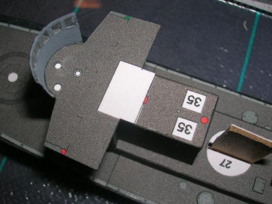

-
Intro to Card Models Part VI: Building V108 - The Superstructure
ccoyle replied to ccoyle's topic in Card and Paper Models
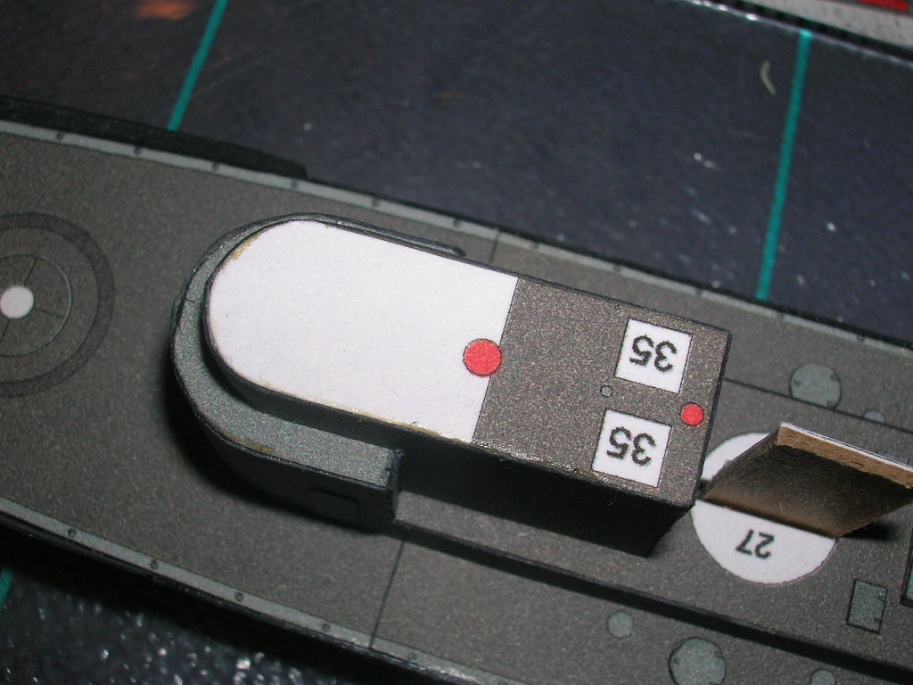
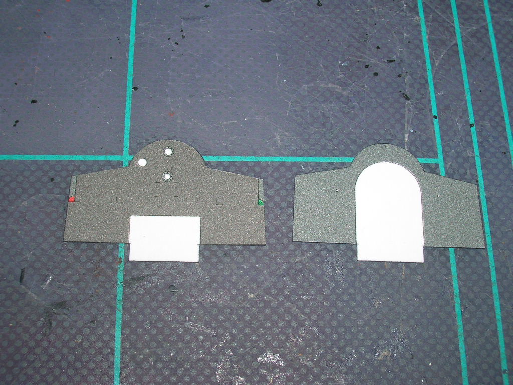
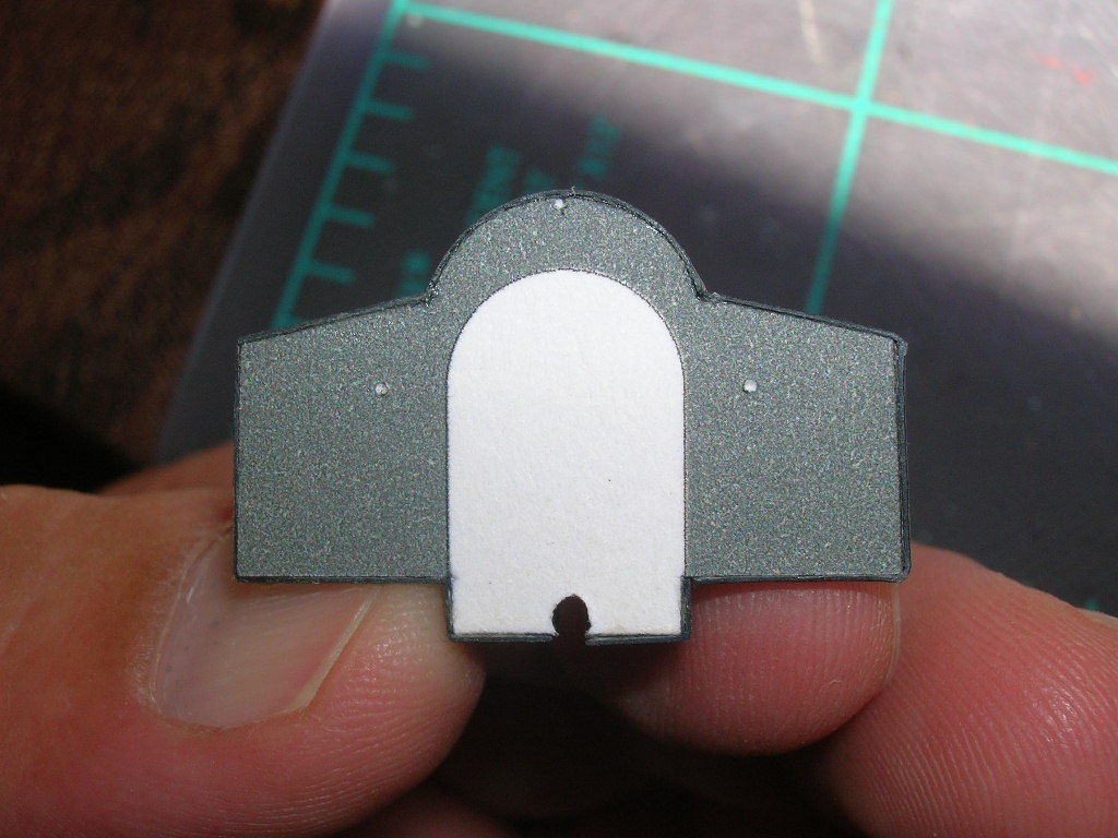
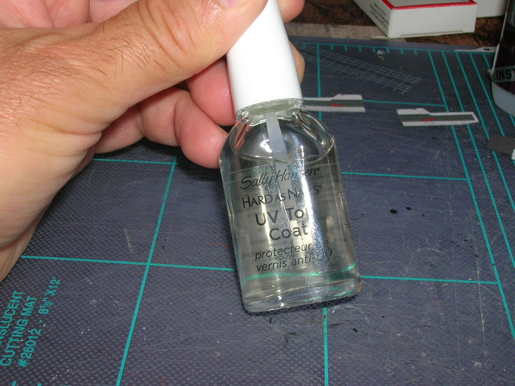
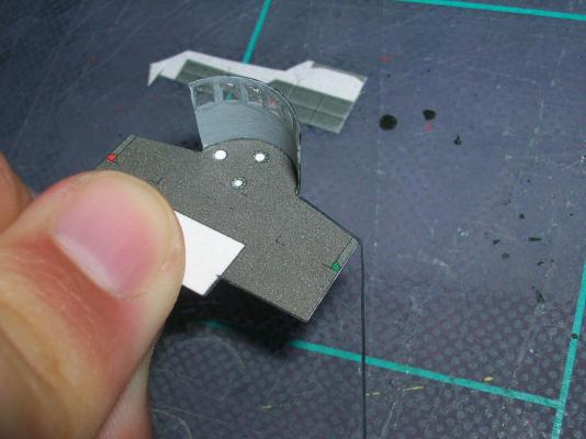
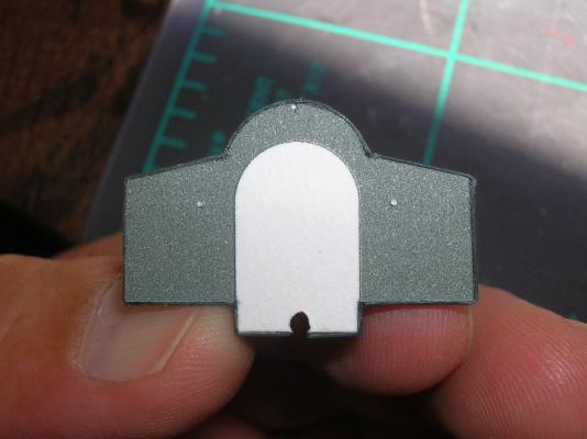
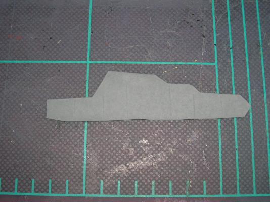
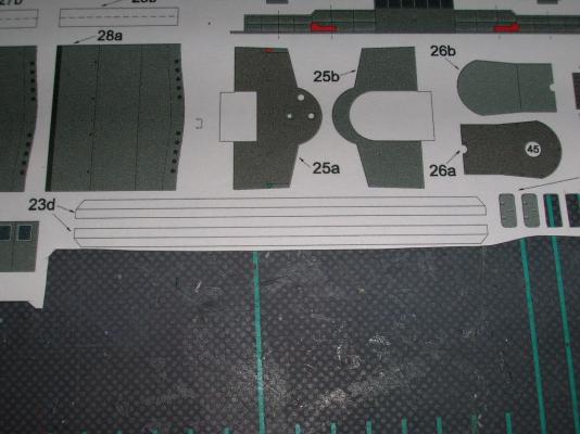
OK, now it's on to the bridge! This will be an interesting part of the build, because it has numerous tiny parts and also presents a number of options for improving the model. We start with parts 25a (top of bridge deck) and 25b (bottom of bridge deck). Glue these together with some contact cement. Notice that on the bottom of the bridge deck, there are three very small white spots; these are locator marks for the bridge deck supports to be added later. To make these marks more functional, we need to drill them out a bit. I use a small finger drill I made by gluing a #73 wire-sized drill bit into a short section of bamboo skewer. Drill carefully so as not to drill all the way through the card - we want just a shallow socket (drilling 25b before gluing the two parts together would avoid this difficulty). Next we'll add the bridge wall, part 25c. The back of this part needs to be colored, so before removing it from the sheet, I gave the reverse side a coat of gray primer (you can see the scored fold lines through the paint). At this point, you need to decide if you want to use the basic part as-is, or make some modifications. These are completely optional, so don't feel any pressure to add them - it's supposed to be fun after all. The first option I will show you is glazing the bridge windows. First you'll need to very carefully remove the printed windows. Remember to cut away from the corners! Also, note that there is some subtle, printed shading on the windows - there's the obvious, light-gray portion of the frame, but there's also a far less obvious, dark gray portion of the frame that is almost identical in color to the 'glass' portion of the window. Take care to remove only the glass areas, or the frames will be unnecessarily thin and delicate (they'll be delicate enough already!). The insides of the frames need to be colored. The space is too cramped for a marker, so I colored these with acrylic paint - the bottle says "Japanese Navy Gray", but I've modified the color at least once in the past, so I don't know what shade it is now. The next option to decide on is whether to use the printed bridge railings or not. If you study the part carefully, you'll see that the railings are actually meant to portray railings covered by storm canvas. You can either go with the printed railing, or you can choose to replace them with either bare railings or more realistic storm canvas railings. I'll be adding scratch-built storm canvas railings; that being the case, the next step is to remove the railings portion of 25c (but don't discard them - we'll need part of them later). Skip this step if you use the printed railings. I'm also removing the side entrance fascias at this point, since it will be easier to add them later as separate pieces. The bridge wall needs to be formed before glazing the windows, else we'll damage the glazing. Here I'm rolling the bridge wall over the handle of my hobby knife. Now, what to use for glazing? There are numerous materials that can be used for glazing. In the past, I have used microscope slide slip covers (great material, but stiff and therefore ill-suited for curved surfaces), clear report covers (flexible, but don't glue well), window envelope panels (crinkle easily), and clear acetate overhead projector sheets (flexible, but don't like to hold a curve). Microscale makes a glue called Crystal Clear that dries clear and can be used for glazing small windows like these, but I don't have any. I'm a big advocate of the card modeling philosophy of "use whatever you can find around the house", and in this case what I found was my teenage daughter's top coat nail polish. This I worked into each window until a film filled the entire window space. The top coat dries fairly quickly. It doesn't dry perfectly clear, but it does dry clear enough to suggest real windows are there, and that's the effect we want. Here's the finished windows: Notice there's top coat residue around the windows - this is why the clear coat is applied only from the inside of the bridge wall. Once it dries, the area around the windows can be touched-up with paint. The finished bridge wall is glued to the bridge deck with contact cement, although I had to tack the outermost corners with a spot of CA to get them to stick tightly. Next: adding interior bridge details.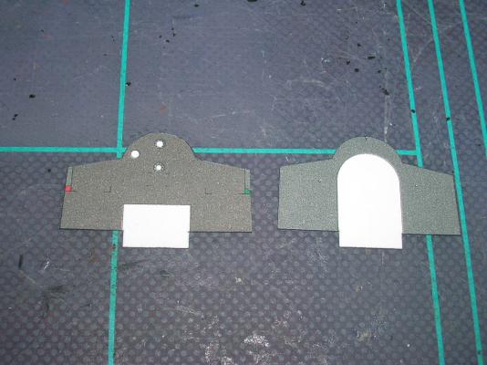


-
Intro to Card Models Part VI: Building V108 - The Superstructure
ccoyle replied to ccoyle's topic in Card and Paper Models
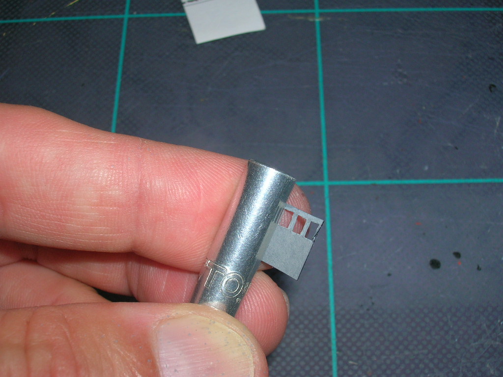
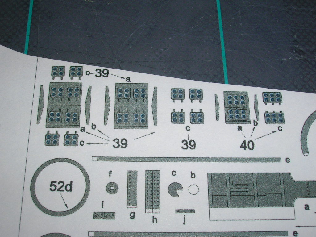
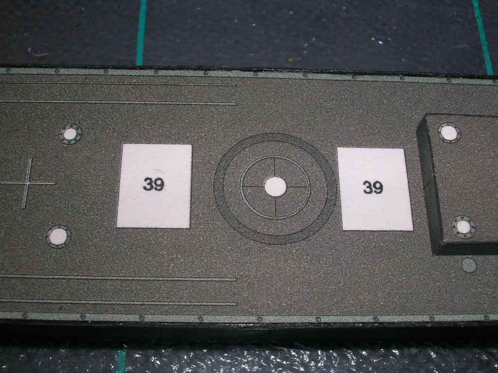
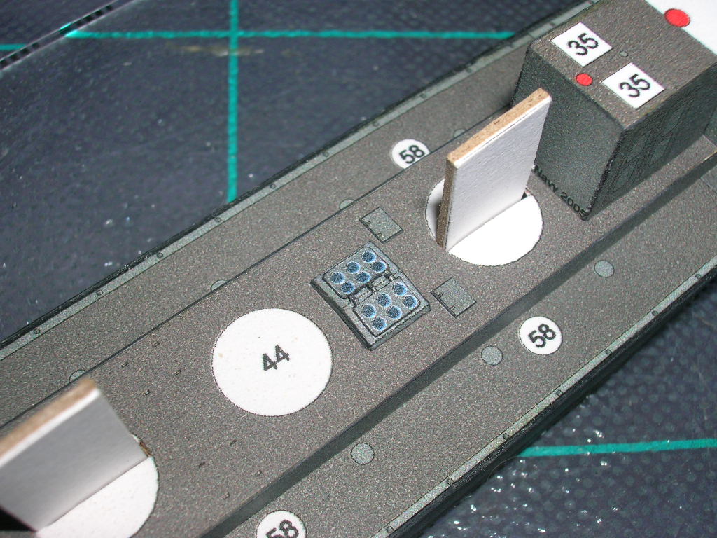
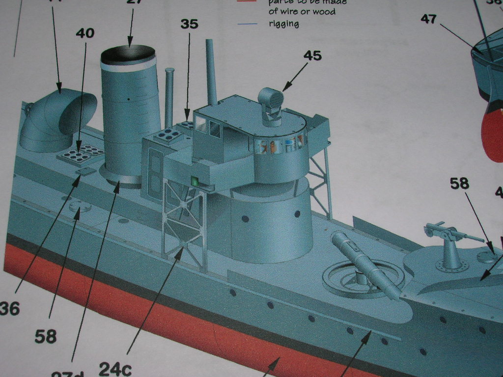
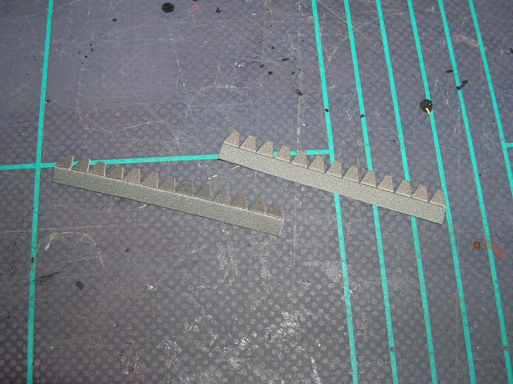
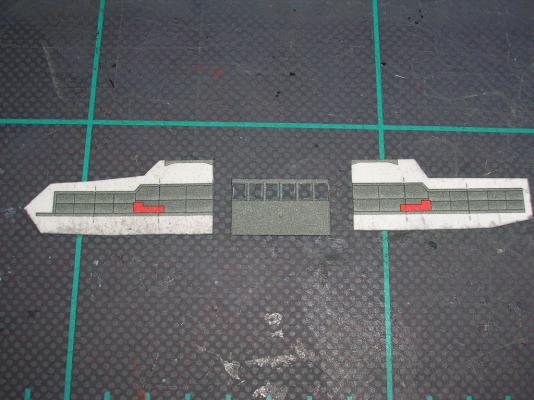
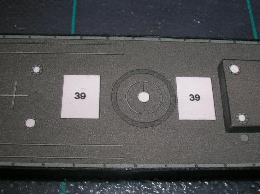
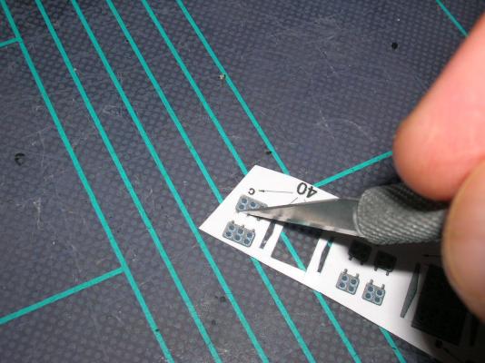
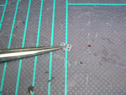
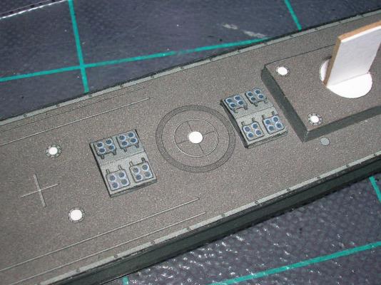
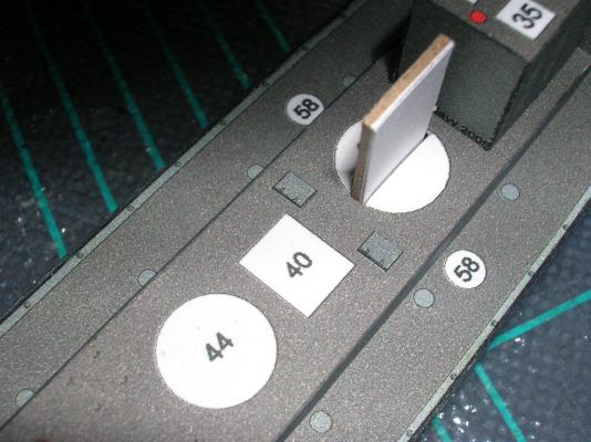
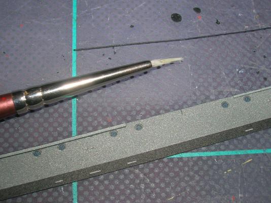
Building the skylights will introduce a couple of new techniques. There are three skylights on the model, built using parts sets 39 and 40. Parts 39 are two larger skylights located abaft the superstructure... ...and parts 40 are the skylight abaft the forward stack. The only thing difficult about building the basic skylights is that the parts are now getting somewhat tiny and awkward to work with (tweezers, people, tweezers). Parts 39a and 40a each have three fold lines to score, and the folds at the edges are almost 90 degrees, so the finished edge there will need some touch-up coloring (visible in the photos of the completed skylights). Score the lines, cut out the parts, and make the folds. When making the edge folds, it helps to grip the edge of the part with fine-tipped tweezers rather than pudgy fingers. Parts 39b and 40b are designed to fit inside folded parts 39a and 40a; medium-cure CA is useful in this situation to get the tiny parts to grip quickly and hold securely. Parts 39a and 40a have the skylight hatches printed on them, but you may choose to add optional doubled hatches (parts 39c and 40c). These have tiny hinges, and the challenge here is how to cut the parts out without losing the hinges (if the challenge proves too difficult, just cut the hinges off - it won't make much difference). When cutting out tiny parts like these, there are two techniques that will help greatly. First, always cut away from inside corners, not towards them. When cutting, the edge of your blade makes about a 45 degree angle to the cutting surface, and thus the heel of the blade finishes the cut at the top of the paper before the tip finishes at the bottom. So, if you cut towards an inside corner of a part, the heel of the blade necessarily cuts into the printed area before the cut is completed all the way through the paper. Second thing to be aware of is that as you draw your blade across a sheet of paper, you are actually pulling at the paper's layers of fiber. As a result, the last layer of fiber at the bottom of the sheet of paper may actually tear rather than cut cleanly. This isn't so bad on a large part, which can be trimmed, but it can be disastrous on ultra-tiny parts like the hatch hinges. So how does one avoid this tendency to tear? Simple - one doesn't pull the blade! One pushes it instead, and here's what I mean: In the following picture, I'm cutting out one of the 40c skylight hatches. To cut the top edge of the hatch between the hinges, I start with the tip of my #11 blade right on the inside corner and push the blade down into my cutting mat. This downward push actually cuts more than half the distance from the first hinge to the second. To complete the cut, I reverse the part, and do the same thing starting at the opposite inside corner. I use this same push-cut technique to do all the cuts along the hinge edges as well. I cut all the hatches out rectangular to start with, but the corners are actually very slightly round, so the corners need to be removed. The hatches are too small to effectively hold down with a fingertip while cutting, so I use the points of my tweezers instead. Edge-coloring the tiny hinges can be troublesome, because the delicate hinges are easily damaged. For these, I hold my marking pen lightly against the inside corners and allow the paper to wick the color into the edges. Once all the hatches are cut out and colored, they are glued down to the skylights with PVA, and the finished skylights are mounted to the model.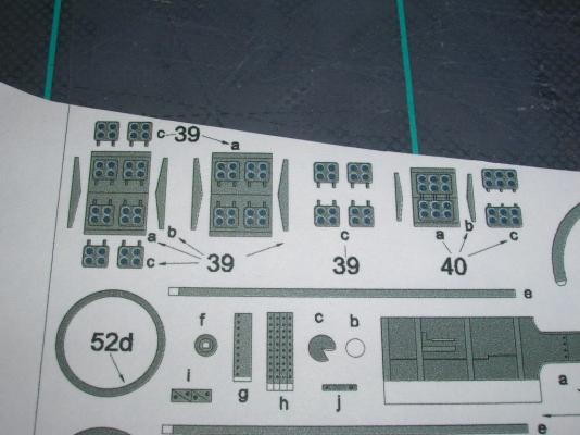
-
Intro to Card Models Part VI: Building V108 - The Superstructure
ccoyle replied to ccoyle's topic in Card and Paper Models
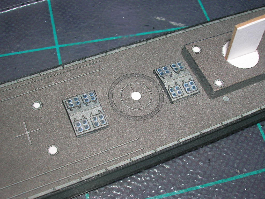
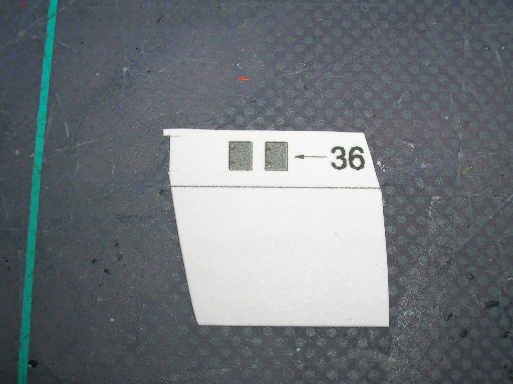
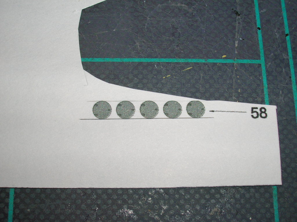
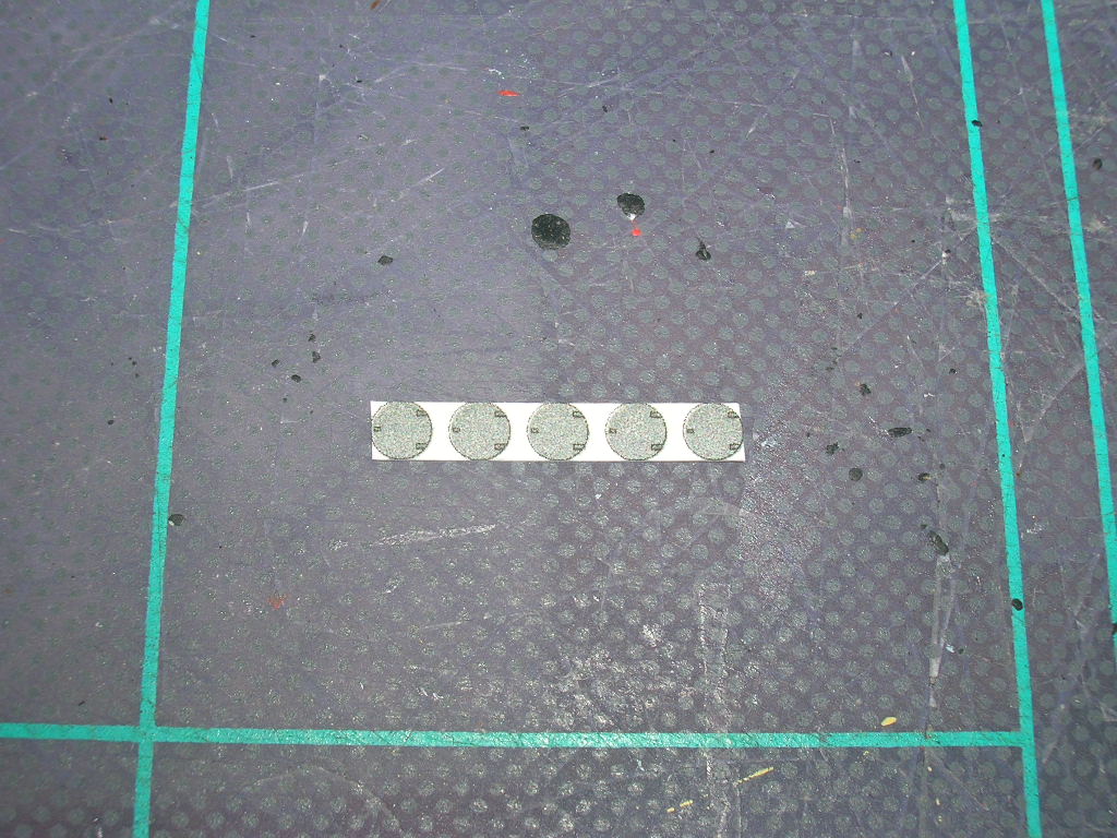
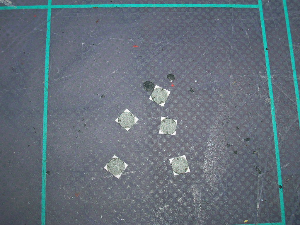
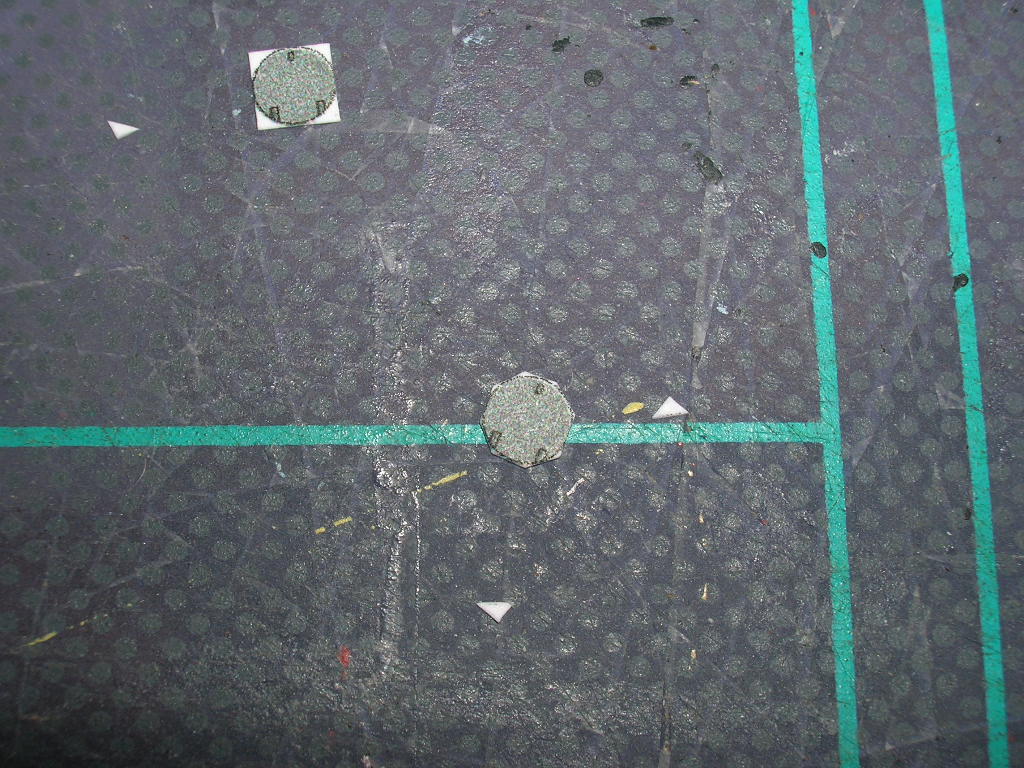
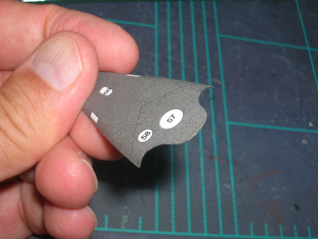
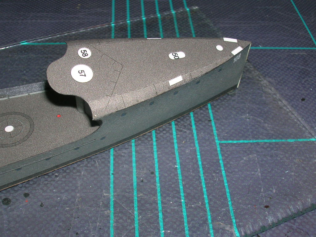
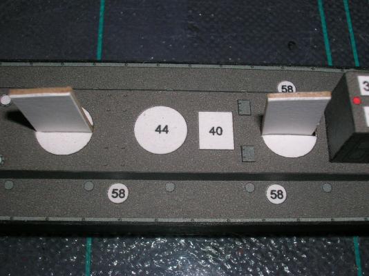
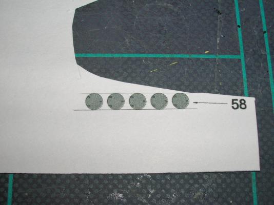
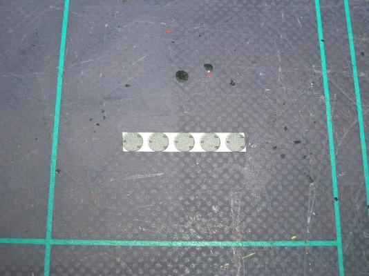
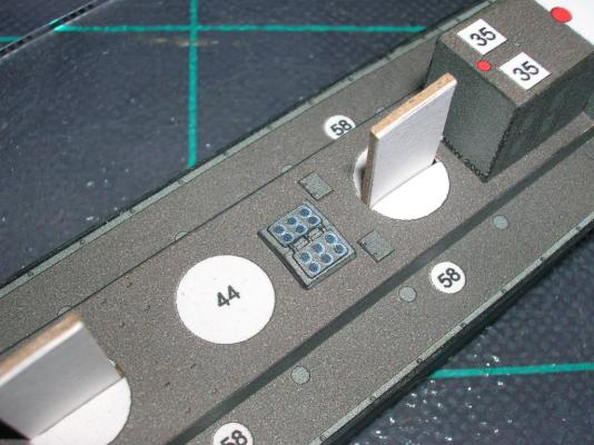
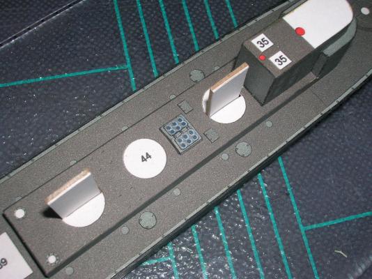
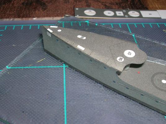
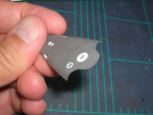
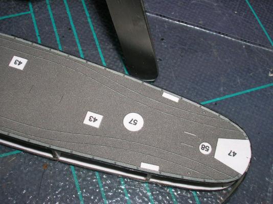
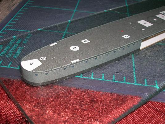
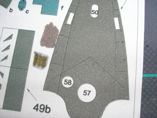
Thanks to those of you who voted in the poll (all six of you!). Adding the extra detail won in a landslide (can there really be a 'landslide' with only six votes??). All this is moot, however, as upon further study of the diagrams it appears that the bridge is not actually fully enclosed, so the detail is necessary in any case. The only real 'option' is whether to replace the printed windows or not. Since the windows are only printed on one side, they either have to a) be colored on the inside of the part, or b) cut out and replaced with glazing. More on this later... In the meantime, I only had a little time to work on the model, so I tackled some of the deck details. It is perfectly acceptable to work on the parts out of sequence, but it is a good idea to keep two things in mind, namely 1) remembering or noting down somewhere which sub-assemblies you have already completed, and 2) avoiding adding details that are likely to be in the way of something later in the construction sequence. With these two provisos in view, I started by adding some of the flat deck parts. First is parts 36. These are hatches that go just aft of the forward stack. The only thing important about them to be aware of is which side do the hinges go on; in this case, the hinges go aft. Next I added parts 58 (fuel bunker hatches). These give us an opportunity to learn another technique. Cutting each of these small, circular parts out individually would be tedious and also very hard on #11 blade tips, because the short radius of the cut stresses the blade tip and increases the likelihood of breakage. Instead, start by cutting all five hatches out as a single strip. Next, use the heel of the blade like a miniature paper-cutting machine to chop the strip into five individual squares, each with a hatch. In the same fashion, take off the four corners of each square. Now each hatch is on an octagon. Finally, trim off the last remaining bits of white and edge-color the hatches. The finished part isn't truly circular, but hexadecagonal. But at this scale, who can tell the difference? Mount the five hatches at the places indicated on the model (one at the stern, three amidships, and one at the forecastle), noting that again the hinges go aft. And, yes, I know there is a skylight in those pictures! That will be the subject of the next post.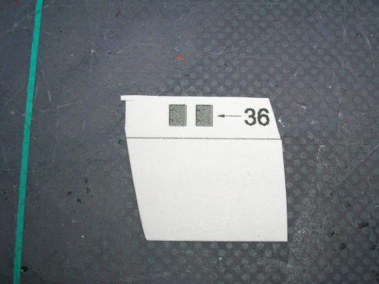


-
Intro to Card Models Part VI: Building V108 - The Superstructure
ccoyle replied to ccoyle's topic in Card and Paper Models
That's certainly possible -- I downloaded mine years ago. Makes me wonder what else may have been updated. -
Intro to Card Models Part VI: Building V108 - The Superstructure
ccoyle replied to ccoyle's topic in Card and Paper Models
Okay -- decision time! The kit includes optional parts for detailing the interior of the bridge. Adding them will require removing the printed windows and glazing them, coloring the interior walls, and adding some particularly fiddly parts. Do you want the tutorial to include these optional parts, or no? I won't be able to do much work on the model for the next 24 hours, so I'll leave the poll (see top of page) open until then. Now, vote!
-
Intro to Card Models Part VI: Building V108 - The Superstructure
ccoyle replied to ccoyle's topic in Card and Paper Models
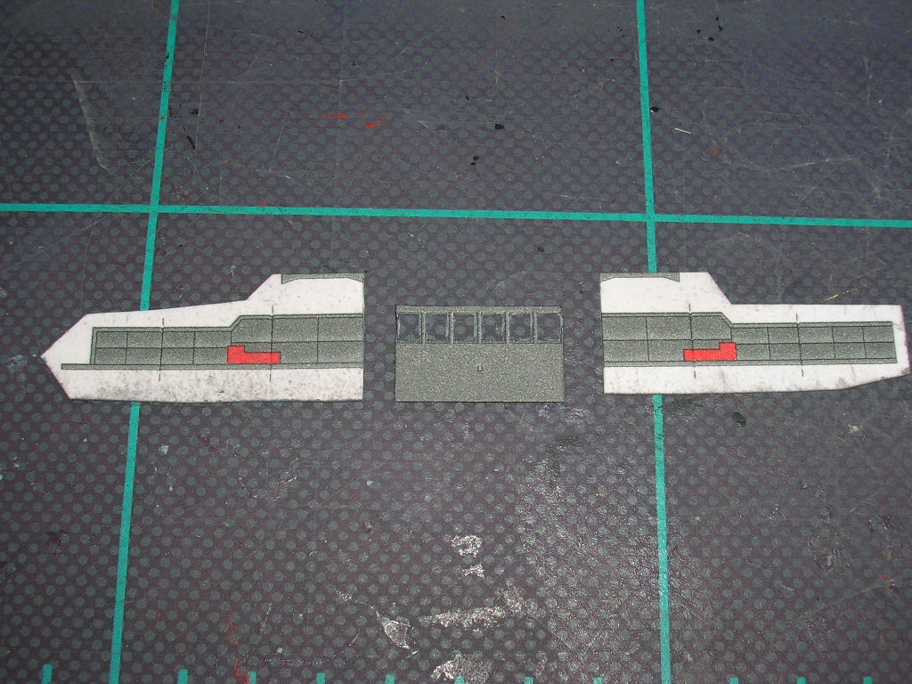
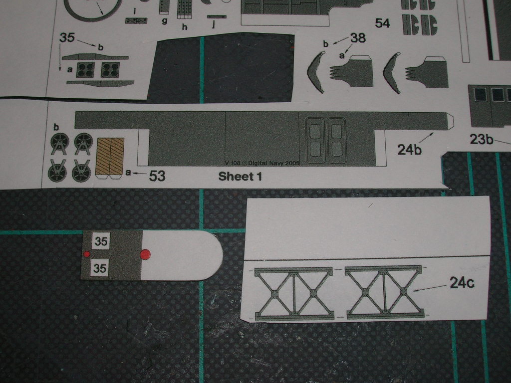
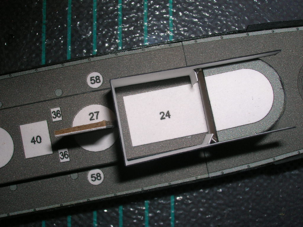
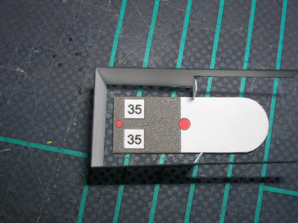
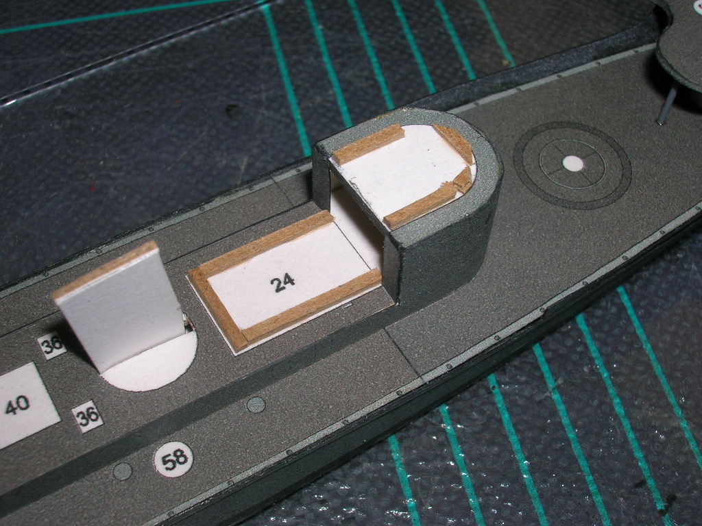
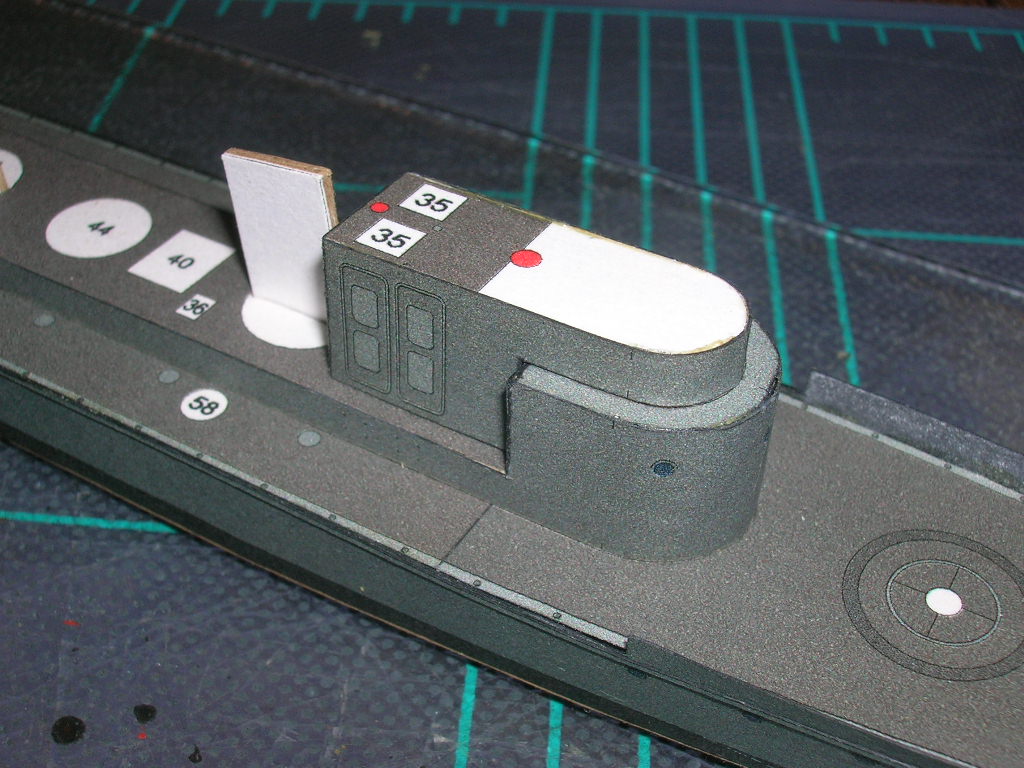
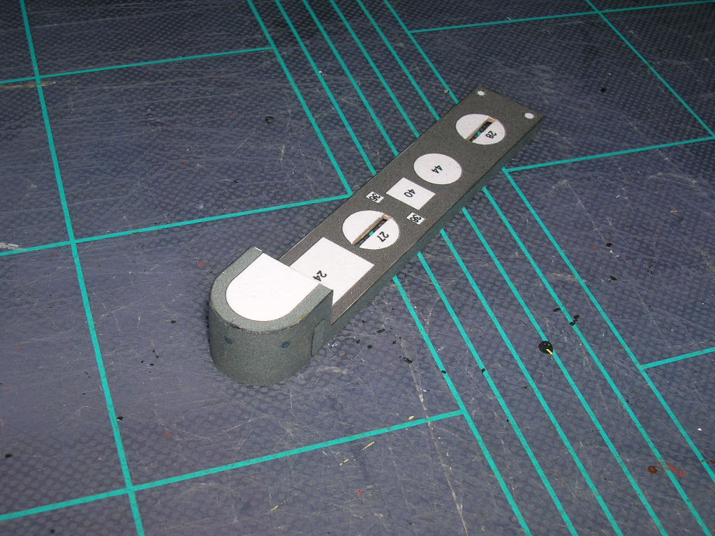
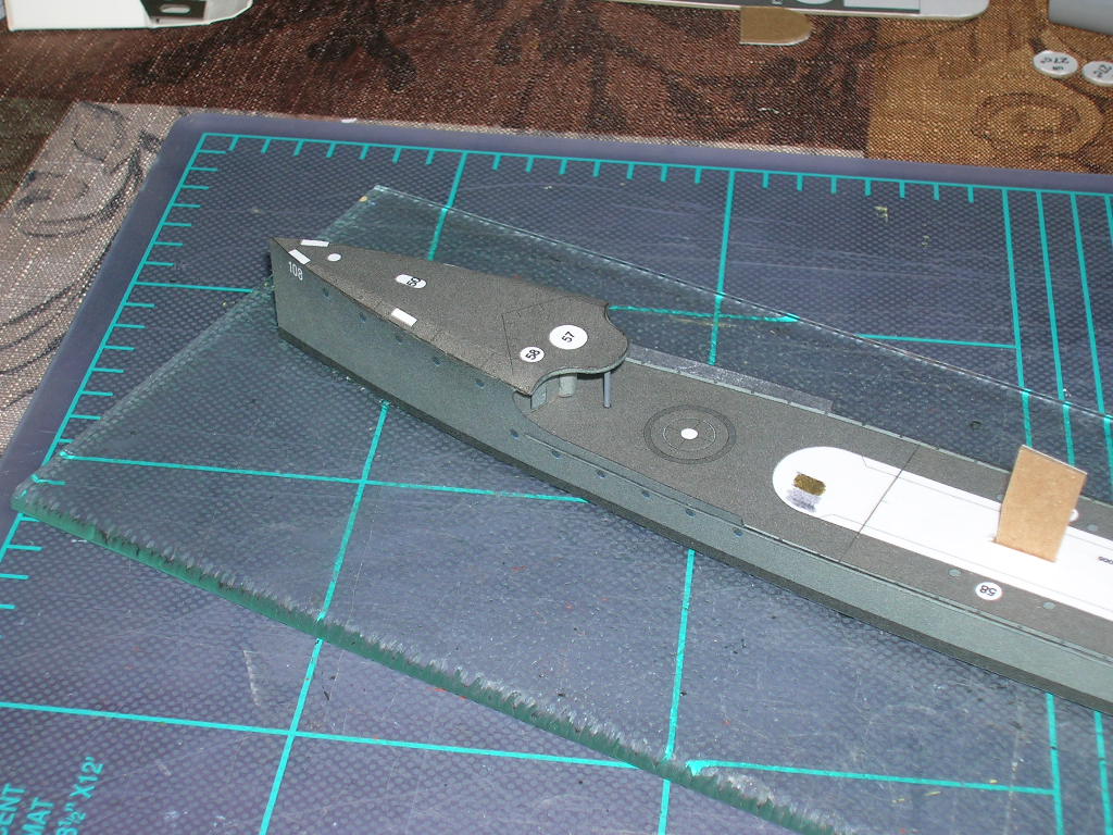
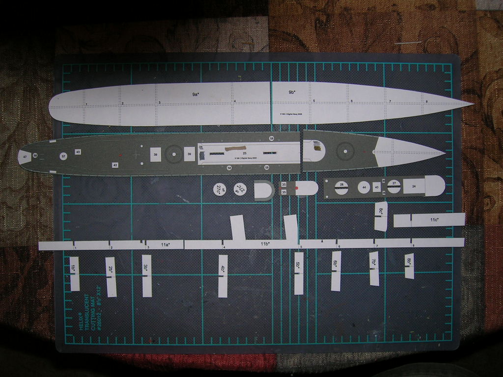
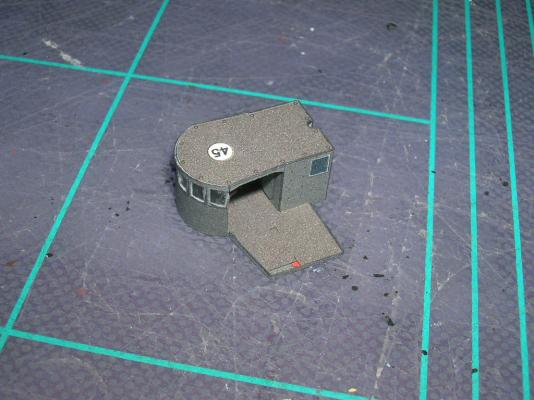
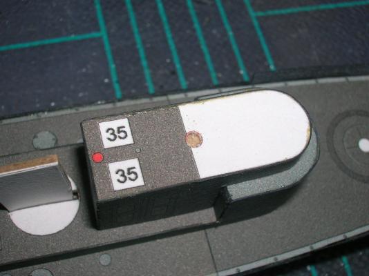
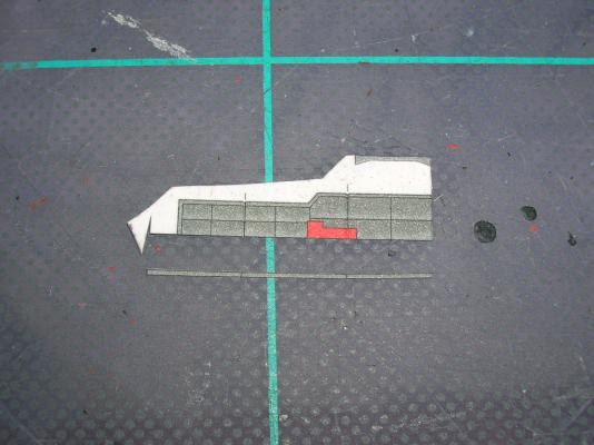
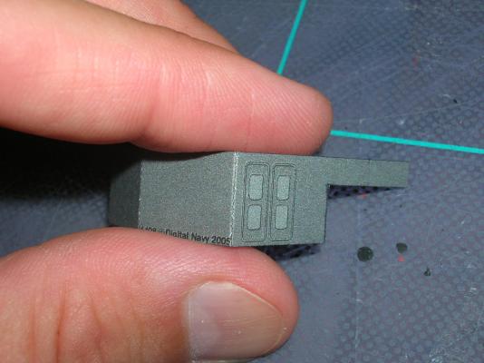
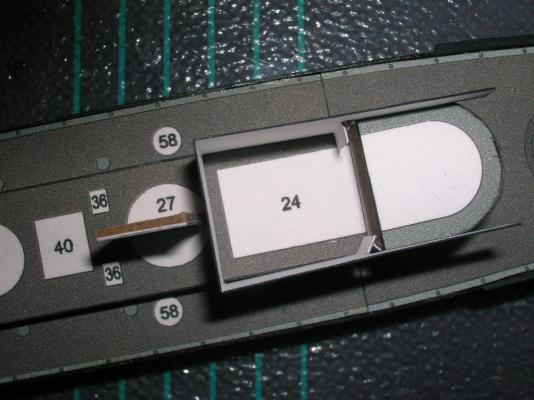
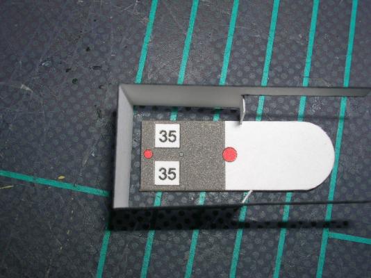
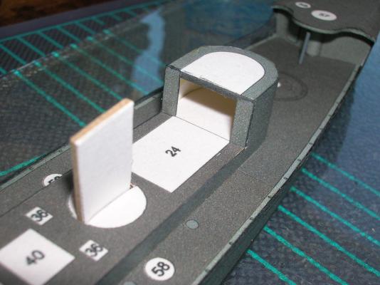
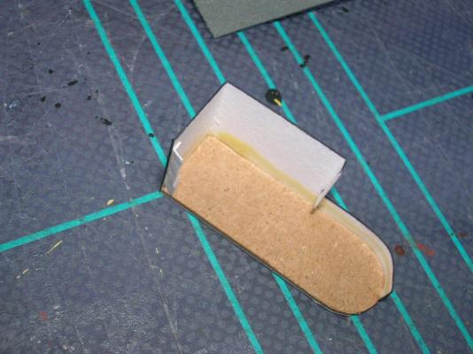
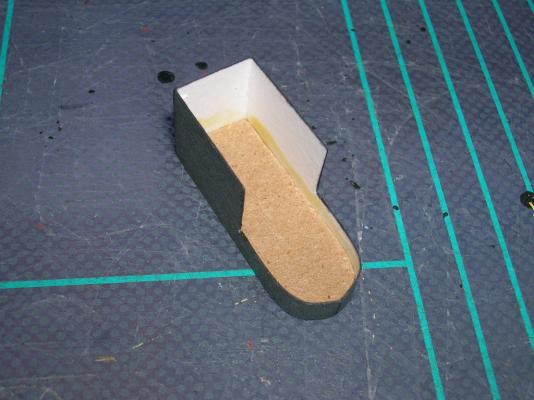
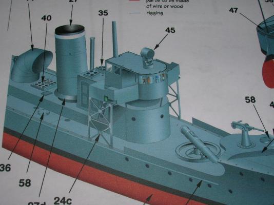
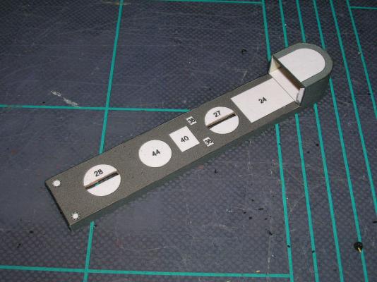
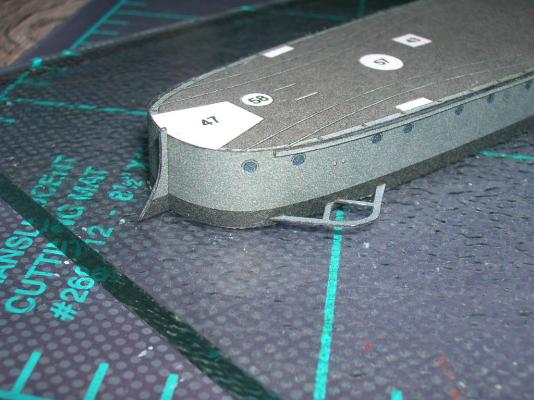
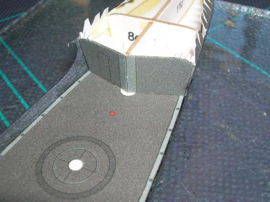
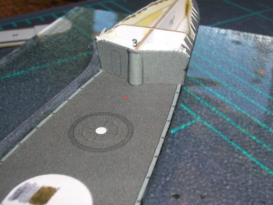
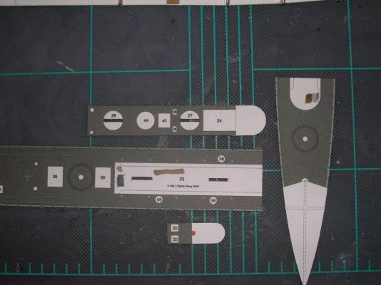
Next up is the conning tower. The first thing to take note of is the parts are misnumbered. This is not an uncommon error in card models, where the model, the diagrams, the parts sheets, and the instructions are often all produced by one person -- without the benefit of a proofreader and perhaps also without the hindsight of a beta build. So, no big deal. The misnumbered part is 27d, which should be 24a. You'll also need 24b. 24c are the bridge wing support girders, which we won't need right away. Normally, I would tell you to cut out 24b after scoring the fold lines and form it, but here's where you get the benefit of my building the model first. There's a big error with part 24b -- once it is cut and folded properly, it doesn't fit! So here's how I fixed the problem. Cut part 24b apart along one of the rear fold lines. Measure and remove the excess part of the rear panel. We're going to put this excess colored panel to work. Notice that at the back of the conning tower portion of the parts 23 sub-assembly, there are two glue tabs; those should actually be part of the conning tower wall. Use the scrap piece from part 24b to make two rectangular panels to cover those glue tabs. The finished task will look like this: Part 24b is now in two pieces. Glue the part with the rear wall to part 24a (the misnumbered '27d'). Now, use some scrap card to create a joiner tab for the two parts of 24b. Attach it thus: Add the rest of 24b (don't forget to color edges as you work!). So -- problem fixed. Next, add some joiner strips to the outline on top of the superstructure. Glue the conning tower down with some white glue. This assembly is a good example of the relative ease with which fit problems like this can fixed in the card medium. I don't think plastic or resin would have been as easy! One other thing to take note of in this section is what happens when you create a 90 degree fold in card: The ink layer is only on the very surface of the paper; very sharp bends will tend to crack this layer. Make sure to color the resulting exposed card fibers, either by painting or running a marker along the fold.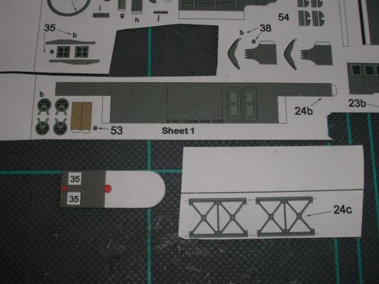


-
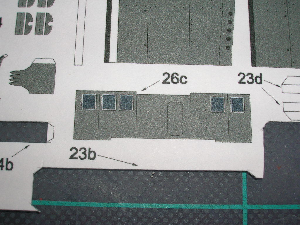
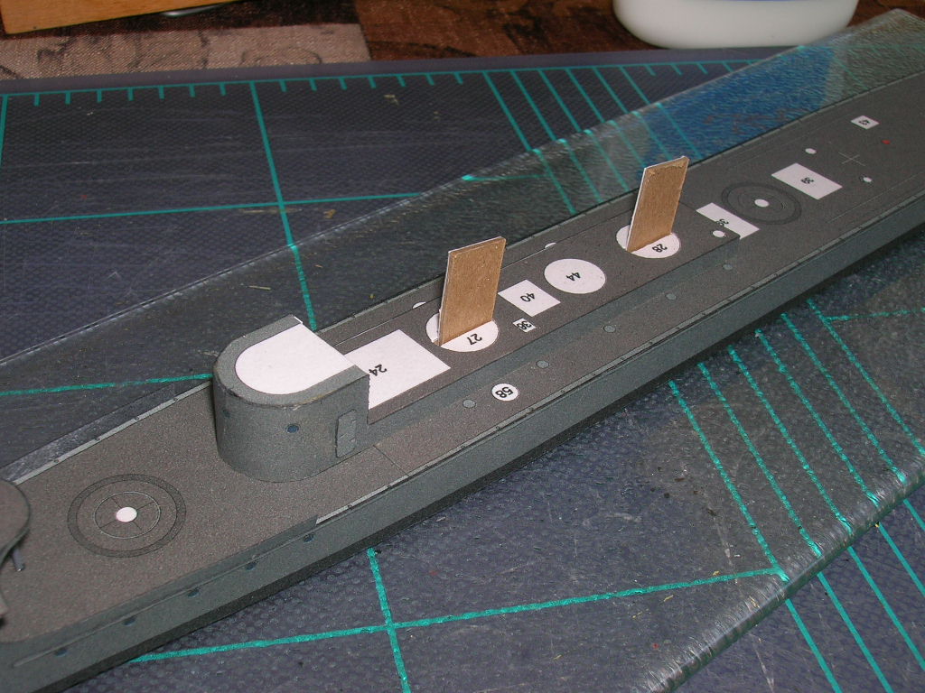
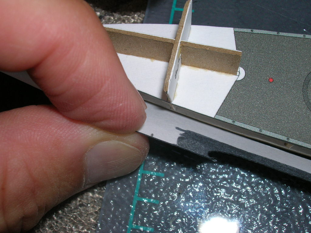
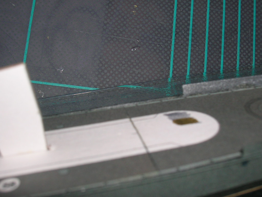
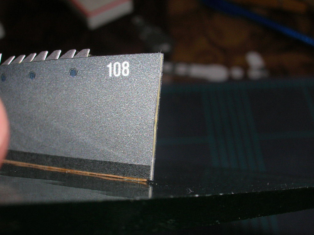
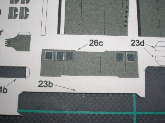
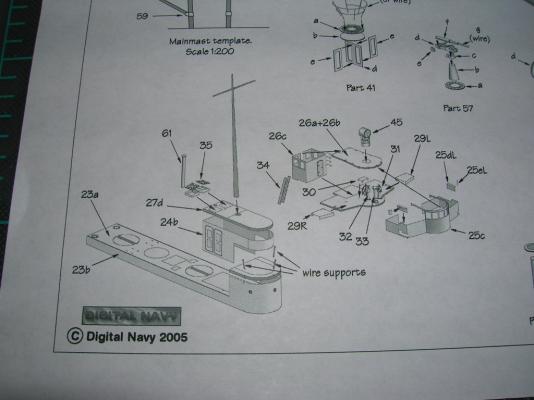
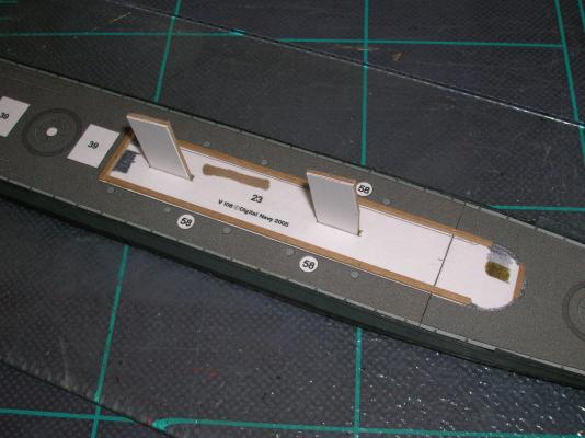
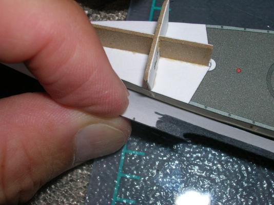
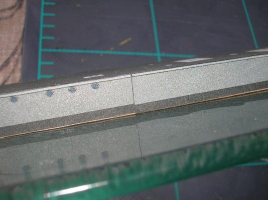
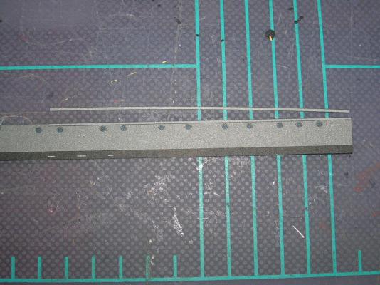
Before starting the superstructure, take a few moments to study the diagram for that assembly. The cover sheet artwork also has a nice view of that part of the ship. Assembly of the superstructure starts with wrapping the walls (23b) around the deck piece (23a). Score the fold tabs on 23b, along with the two fold lines where the wall wraps around the aft corners of 23a; after cutting it out, add the hatch door on the port side (part 55), Now here's another tip - if you apply contact cement to only one surface to be joined, it doesn't grab as tightly as when both surfaces are coated, but it does allow a small amount of working time. I glued 23a and 23b together with contact cement in the following order, applying the contact cement incrementally only to 23b: starboard rear corner, starboard wall, front of the bridge, port wall, port rear corner. When I got to the rear port corner, I discovered that the wall, 23b, was about 0.5 mm too long; if this happens to you, just trim the overage away from the end of the wall, crimp a new corner where the wall and corner meet, and then finish attaching the wall. After the wall is completely attached, the superstructure roof (23c) can be added using PVA. The finished assembly looks like this: If you study the last image carefully, you can spot a minor error. While I was dry-fitting 23b around 23a, the assembly slipped from my fingers. It is a very rare person who can suppress the reflex to grasp at a dropped object, and I'm not that person! As a result, there occurred a crease in the forward bridge wall (it runs down through the front porthole). When card is creased like that, the crease is pretty much there forever. Next, the superstructure assembly needs to be mounted to the main deck. The kit supplies a couple of joiner strips for this task (parts 23d). I happen to dislike such joiner strips for this job. When paper is folded, the fibers in the paper have 'memory' - they want to return to their previous shape. As a result, folded paper acts like a weak spring. In this case, the folded joiner strips will have a tendency to push the superstructure assembly upward. To avoid this, and to do a better job of positioning the superstructure walls, I prefer to add locator strips to the model. These can be made from leftover chipboard or strip wood, if you have any lying around (what ship modeler doesn't?). Here, I've sliced some ~1 mm wide strips from the edge of a chipboard sheet. These are then cut to the appropriate length and glued down to the main deck just inside the superstructure outline. The idea here is that the strips will position the walls exactly where they need to be, right on top of the outline. Notice I've cut and shaped a piece for the curved forward bridge wall as well. By the way, those colored patches on the deck are where I tested some markers for color matches to the kit. I used ordinary white glue to mount the superstructure, because the fit with the locator strips is tight, and I wanted as much time as possible to get all the walls down over the locator strips. The mounted superstructure should look like this, with nary a bit of white peeking from beneath the walls: Back to Part V: Building V108 - The Hull


-
Intro to Card Models Pt. V: Building V108 - The Hull
ccoyle replied to ccoyle's topic in Card and Paper Models
Jan, For this build, I'm using the same felt-tipped marker that I'm using for the edges. For other builds, I have used acrylic paint matched to the color of the kit. -
Intro to Card Models Pt. V: Building V108 - The Hull
ccoyle replied to ccoyle's topic in Card and Paper Models
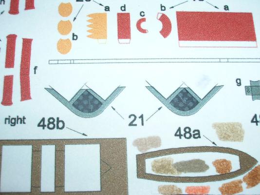
Ack! Almost forgot a few hull details. Parts 21 are the propeller guards. Small parts like these that have substantial cut-out areas are flimsy once removed from the sheet, so it helps to do some of the prep work while they're still on the sheet. Start by coloring the reverse sides of the parts. Then, cut out the inside white areas, but leave the outer edge attached. You can then edge-color the interiors of the parts. When the interiors are done, remove the parts from the sheet and color the outer edge. Glue the guards to the hull with small amounts of PVA. Note that the guards follow the curvature of the stern, so the left and right guards are not interchangeable. The rudder (part 22) introduces a new kit feature, the two-sided part. Score the fold line, then cut out the entire rectangle containing the part. Apply glue to one-half of the back side of the part, then fold the rectangle in half. You now have a rudder colored on both sides! Remember, though, we're only using the part above the waterline, so go ahead and remove the red portion. Color the trailing edge and then glue the rudder to the stern; there's a locator mark there to help you. The rudder post will stick up above the deck just a little. Here's the guards and rudder installed: Okay, now we can move on to deck structures! On to Part VI: Building V108 - The Superstructure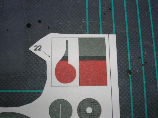
- 37 replies
-
- 4
-

-
- v108
- paper models
- (and 1 more)
-
Intro to Card Models Pt. V: Building V108 - The Hull
ccoyle replied to ccoyle's topic in Card and Paper Models
Hi, Don. There's a discussion of glues in Part IV. -
Intro to Card Models Pt. V: Building V108 - The Hull
ccoyle replied to ccoyle's topic in Card and Paper Models
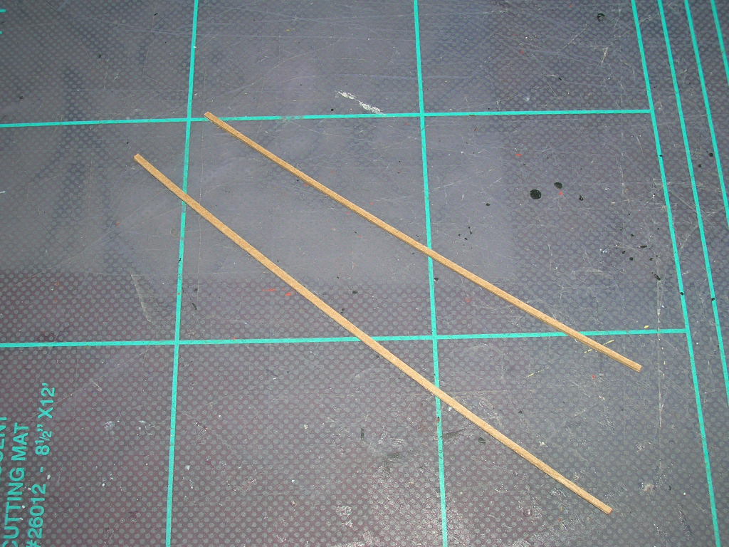
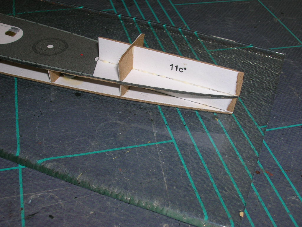
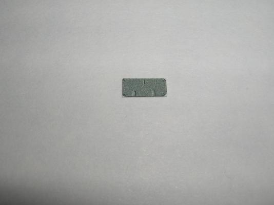
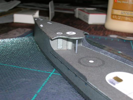
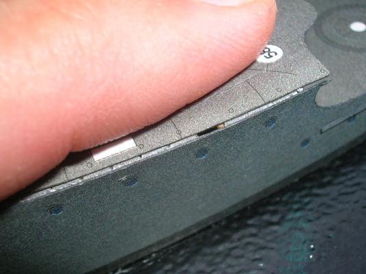
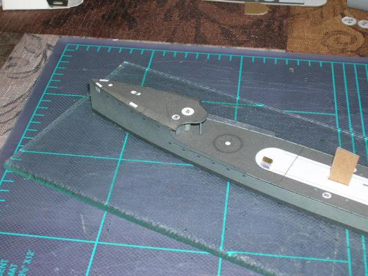
OK, so I cheerfully moved on to attaching the port side of the forecastle deck and came across this: Yeah, that's a gap that didn't want to close, no matter how much I tried to force the two edges together. The culprit in this case is the extra thickness added to the interior former by the joiner strips on either side of the hull. You can avoid this problem by removing a bit of the joiner strip as I suggested in the previous post; I didn't have this option at this point, so I had to resort to Plan B, which was to slice away a tiny bit of the interior former in order to decrease the width. Afterwards, I was able to finish the task. I started by tacking down the forward end of the bow and letting that joint cure, then gluing the deck and hull edges together in the same manner as on the starboard side. When I was working on the forecastle bulkhead, I wondered why the kit didn't include a part for doubling the hatch on the bulkhead. Well, it does -- it just isn't next to part 17 on the parts sheet. The necessary part is part 55 (note to self: it's indicated ON THE DIAGRAM -- always pay attention to the diagram! ). Note that this part has tiny rounded edges. Don't try to cut these curves right away. Instead, cut out the part rectangular, using a steel rule to keep the cuts straight. Afterwards you can use the tip of your #11 blade to nibble away the remaining bit of white from the hatch. Color the edges. This part should be added to part 17 before the bulkhead is glued in, but in case you forget (as I did), the hatch location can fortunately still be easily reached at this point in the build. There's also a support post to add at this point. The diagram says to make the part from wire. You can certainly use wire, but I chose to add an appropriate length of styrene rod. I sprayed the rod with Krylon gray primer, which happens to be a shade of gray suited to the model. Tack the bottom end of the post to the deck with a dab of CA glue (you want this to set quickly); when that dries, set the top end with PVA (you'll need to move the post around a bit until it looks perpendicular to the deck from all viewing angles). The last part to add is part 13b, a sort of fascia. I found that the barrel of a mechanical pencil was the right diameter for forming the curves in this part. There's a locator mark on the part to indicate the center; tack this point to the center rear of the forecastle deck, then work your way bit-by-bit first to one side, then the other, alternating a dab of glue with pressing the fascia to the deck using a fine-tipped instrument (awl, tweezers, paintbrush handle, etc.). Here's the completed post, fascia, and doubled hatch: The basic hull is now done! One thing to keep in mind is that many of the little goofs that pain you to look at during the build process will be far less visible when the model is viewed from a normal viewing distance. See? It's all a matter of perspective. This concludes Part V. Part VI will cover the building of deck structures.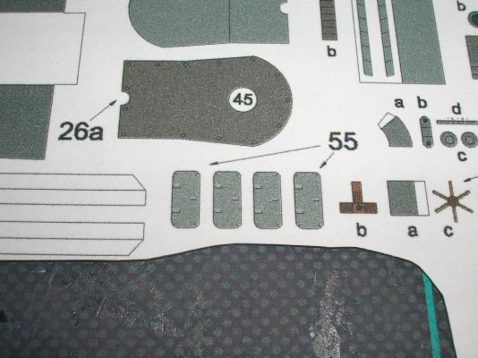
- 37 replies
-
- 4
-
-
- v108
- paper models
- (and 1 more)
-
Intro to Card Models Pt. V: Building V108 - The Hull
ccoyle replied to ccoyle's topic in Card and Paper Models
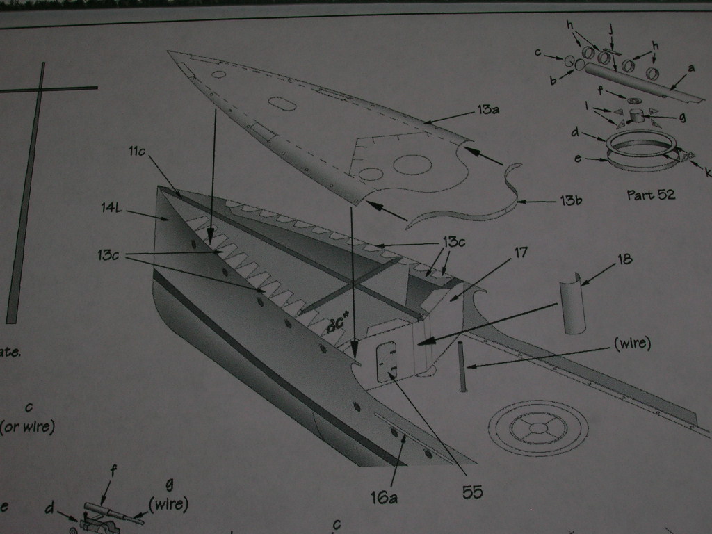
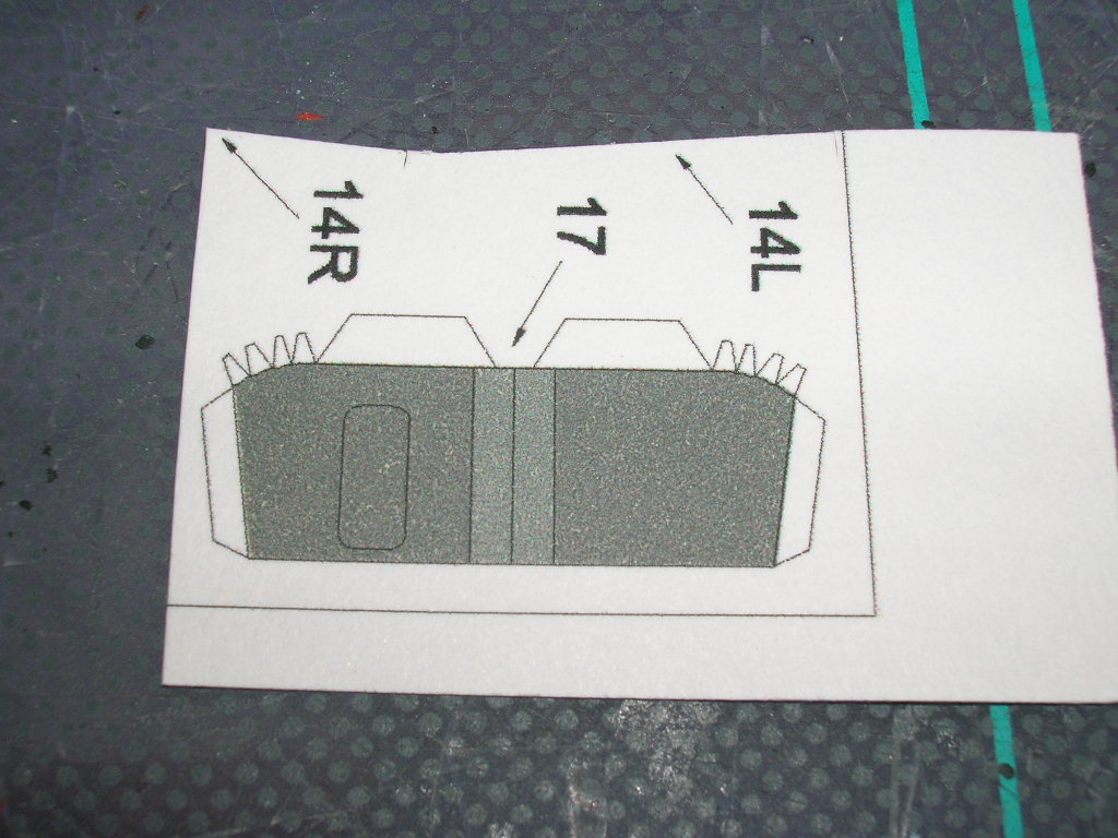
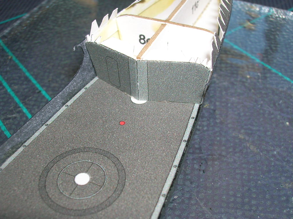
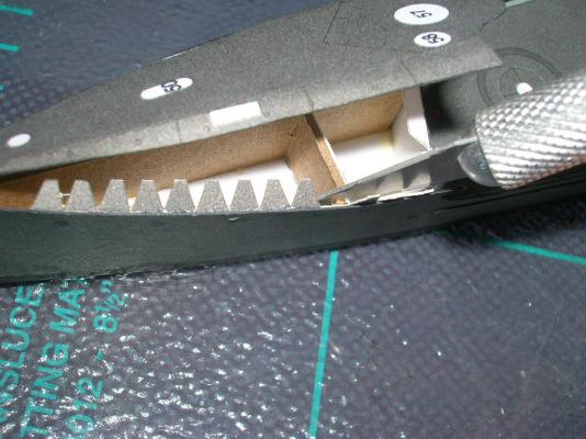
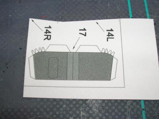
The forecastle has its own diagram. Study it carefully. We'll start with part 17, the forecastle bulkhead. Notice that the part has a number of joiner tabs and a fold line down the center. Score the fold line and the bases of all the joiner tabs before cutting the part out. Use PVA glue to install this part, because you may need to play around with the positioning before you get it properly placed. Next comes part 18. I have no idea what it is, but that's not unusual. It has joiner tabs, too, but on a part this tiny the joiner tabs are actually more trouble than they're worth. Go ahead and remove them. Part 18 needs to be rolled into a half-pipe. Moisten the back slightly and start the process by forming the tube around the handle of a small paintbrush or other narrow, cylindrical object. You can finish the forming by gently rolling the part with your fingers. Glue the part to the deck and forecastle bulkhead. Now it's time to do the forecastle deck. First, the edges of the deck need to curl down slightly, more at the aft end and less at the front. The decreasing diameter of an awl tip works well for this sort of job. Take your time with this part -- one of the beauties of paper is that if you over-form the part at first, you can always undo it some. Here's the formed deck ready to install: Gluing the deck in is tricky. To make things easier, we'll glue it down one side at a time. I started on the starboard side. Brush some PVA glue (PVA in case we need to reposition) along the joiner strip teeth and hull edge. Attach the deck and gently press the edges of parts 13 and 14 together with your fingers until the glue grabs. Should look something like this: Coming up next: A big boo-boo!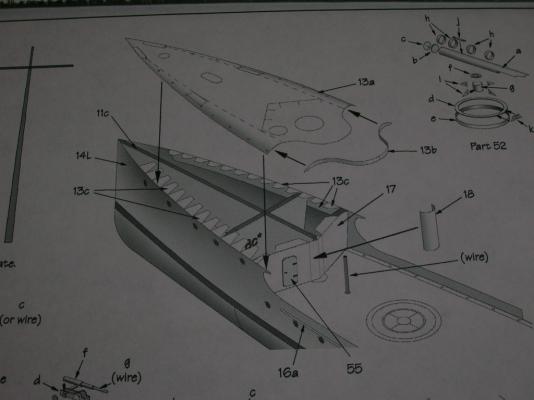


- 37 replies
-
- 2
-
-
- v108
- paper models
- (and 1 more)
-
Intro to Card Models Pt. V: Building V108 - The Hull
ccoyle replied to ccoyle's topic in Card and Paper Models
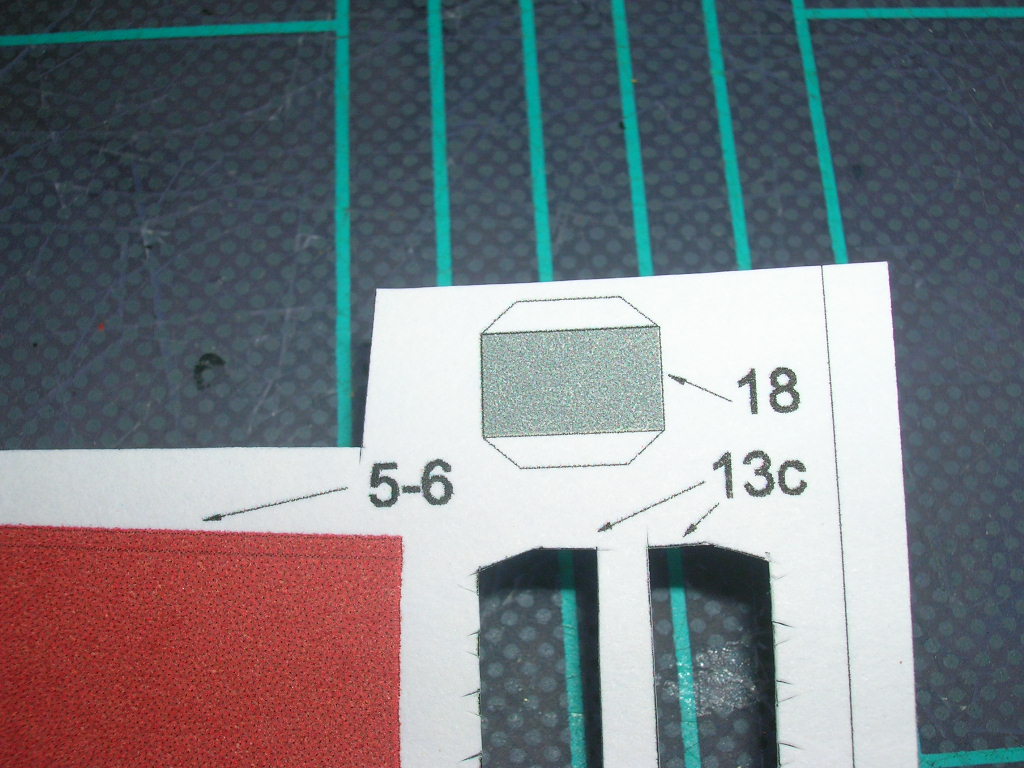
Gonna finish up the hull skins now... First thing to do is add the optional strips 16a to the two hull skins 14L and 14R if you have chosen this option. Apply glue with a brush as described previously and work with about two to three centimeters of strip at a time. Parts 13c are joiner strips, used for joining adjacent parts (parts 13 and 14 in this case). The line along the base of the teeth needs to be scored so the teeth can be bent over. Joiner strips can be problematic. Problem number one in this instance is that the fourth tooth over from the aft end on the joiner strip falls right on the forecastle bulkhead. This is going to add some unwanted thickness to that bulkhead. Solution: remove the fourth tooth. Actually, you'll want to cut the strip into two parts and remove the section that lies on the bulkhead entirely; I didn't, and this caused a semi-major problem later in the build sequence, as you'll soon see. With this tutorial, you get the whole story, warts and all! Mark the inside of the hull skin where the forecastle bulkhead hits it. Then glue the two pieces of joiner strip on either side of the mark, leaving room for the bulkhead (this picture shows the joiner strip as one piece). You are now ready to glue the two hull sides to the frame using the contact cement procedure described in the previous section. Start at the joint with part 15 and work forward. Here you can see that I let part 15 ride up a bit at the front end, resulting in a slight misalignment with part 14R. That's life, kid! You really, really have to be careful with the contact cement. After I got part 14L added to the hull, I noticed that the deck sloped ever so slightly downward on the port side, meaning part of 14L showed above the edge of the deck. Trying to peel the hull skin away and realign will only make the problem worse, so that's the way it's going to stay. That's why I colored the inside edge of part 14L. I also wound up with a slight misalignment at the bow. Probably I will touch this up with a little paint, but I'm going to wait until the model comes off the glass plate. This will be a pretty minor touch-up job. I will also touch-up the tiny bits of exposed cardboard hull base plate at that point. Next we'll do the forecastle, which is one of the more onerous parts of the build.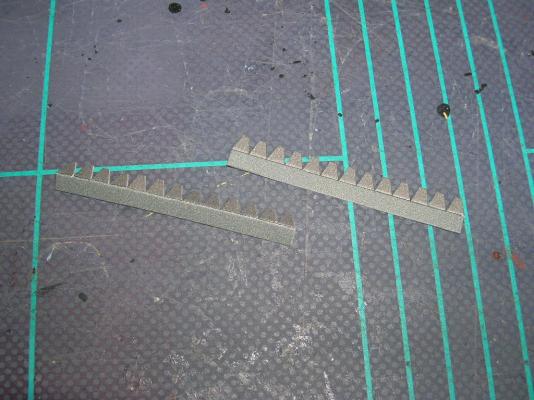

- 37 replies
-
- 2
-
-
- v108
- paper models
- (and 1 more)
-
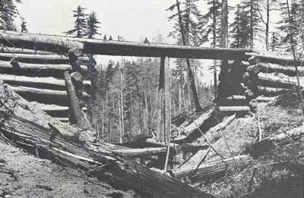
Salvage logging can be an interesting venture. Back in the early 90's, in my fish habitat restoration days, we used to see many small bridges called "Humboldt crossings"; these consisted of two earth-filled log sills overlain by several log stringers, with the spaces between the stringers also often packed with earth, similar to the bridge in this picture, but usually on a smaller scale. At that time, old growth logging was being rapidly curtailed, so timber companies were going in and pulling these structures and replacing them with railroad flatcar bridges. The logs were often still in good condition and the lumber from them was worth thousands of dollars per log, so it made sense economically. To make this post nautically relevant, much of the wood milled from these forests was shipped from tiny west coast ports aboard wooden schooners and sent to booming southern California coastal areas.
-
Intro to Card Models Pt. V: Building V108 - The Hull
ccoyle replied to ccoyle's topic in Card and Paper Models
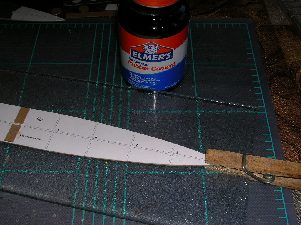
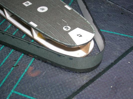
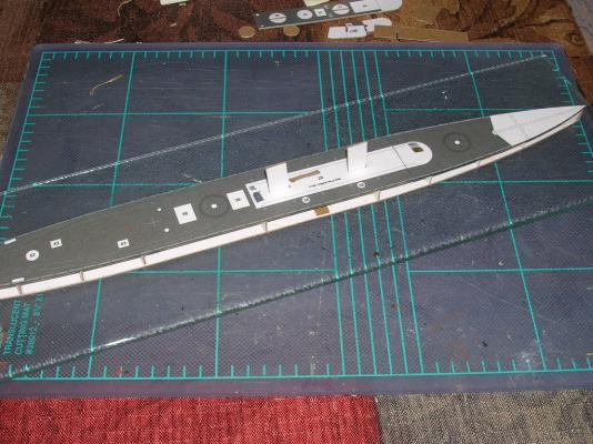
Time to start skinning the model! As I stated in the previous post, we'll start at the stern with part 15. Part 15 wraps around the stern and extends forward to bulkhead 3. We'll need to pre-form the curve at the stern. To do this, you'll need a form to help roll the paper. Here, I'm using the body of my gray felt-tipped marker. Moistening the paper at the point of the bend will decrease the likelihood of the paper crinkling instead of making a smooth curve. Lightly moisten the inside of the part. Licking actually works well, or you can lightly brush on some water. Don't forget to dry fit! And now for another must: contact cement. We'll use contact cement for the skins because it's a non-water-based adhesive and will not warp the skins. It takes some practice to get used to applying the stuff (I was obviously out of practice today! ). Apply the cement to both parts to be joined (skin and frames in this case) and wait a few minutes until it's no longer tacky. Notice that there are locator marks dead-center on both parts 12 (deck) and 15 (hull skin); line these marks up on the two parts and begin applying the skin, working from aft forward, one side at a time. I use the flat side of my tweezers to press the skin to the model -- works much better than fingers. CAUTION! Contact cement is very unforgiving of mistakes! Once it's stuck, it's stuck! So be sure to get it right the first time! And here's your reward for a job well done: a nice, tidy, properly fitted and hopefully not wrinkled or crinkled stern!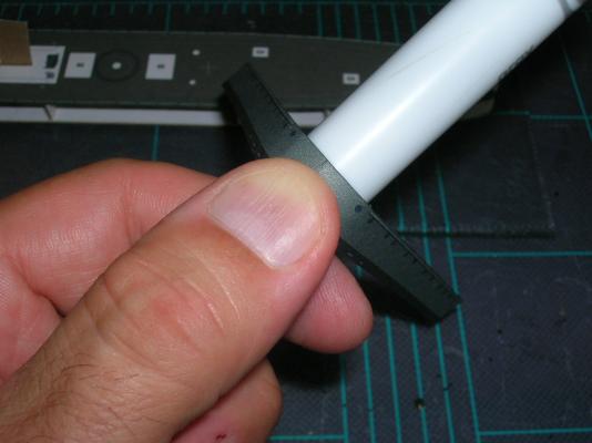
- 37 replies
-
- 5
-
-
- v108
- paper models
- (and 1 more)
-
Intro to Card Models Pt. V: Building V108 - The Hull
ccoyle replied to ccoyle's topic in Card and Paper Models
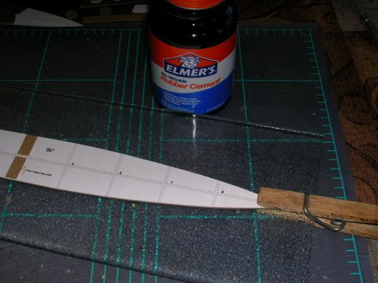
Generally speaking, card model parts are numbered in the sequence in which the designer intended they be assembled, but it doesn't always make sense to follow this sequence. For example, if we follow the part number sequence on this model, the forecastle deck (13) would be followed by the hull side skins (14) ('skin' is the card modeling term for any large outer part that covers the internal frame 'skeleton' -- get it?), and finally the stern skin (15). This is a bad sequence for several reasons. First, there are parts that go under the forecastle deck, and it makes more sense to install these before adding the deck. Second, the stern should be skinned first, for reasons I'll explain later. Stuff like this is why the diagrams and parts sequence should be studied and pondered before doing any assembly. Now, look carefully at the parts sheet where the hull skins are printed (parts 14-16). Parts 16a and 16b are optional rubbing strips; these features are already printed on parts 14 and 15, but by adding the optional strips, you give your model a little hint of depth. This technique is called 'doubling', because you're doubling the thickness of the part. You need to decide now whether to add parts 16, because adding them later will be a huge headache. Either way you decide, there is something very important to take note of in the way the parts are laid out on the page. Notice that if you cut out the parts in the numbered sequence, i.e. parts 14 first, parts 15 and 16 will be left on a narrow strip. If you then continue to cut out part 15, parts 16 will be left on even narrower strips. This, my friends, is very bad. You see, if you then continue to cut out parts 16, the narrow strips will want to splay away from your blade as you cut, and this makes cutting long, thin parts from narrow strips of parts sheet unnecessarily difficult. To do the job right, ignore the numbering sequence and cut out the parts from the outside edge of the sheet and work towards the center. Thus, the cutting sequence should be 14L, 16b, 16a, 15, the other 16a, the other 16b, and finally 14R. Work carefully and note that some of the edges are not entirely straight, but slightly curved. I'm going to show you the assembly sequence with the rubbing strips included. These need to be added to hull skins before the skins are attached to the model. Start by coloring the edges of all the hull skin parts. Part of the inside of 14L and 14R will need to be colored where the bulwark extends slightly aft of the forecastle -- this inside portion will be visible on the finished model. I also color the top inside edge of each hull skin just in case it extends ever so slightly higher than the hull frames. We're going to start skinning with part 15 and work forward, and here's why: If you start with 14L and 14R and work aft, if any error creeps in, the resulting gap will be somewhere amidships. If you start with part 15 at the stern and work forward, any error creep will be at the bow, and fixing that problem at the bow (if it occurs at all) is easier than fixing it amidships. Here's part 15 and one of its two rubbing strips (16b): Use a fine-tipped paint brush to apply a thin layer of glue to half the length of the rubbing strip, and then carefully fix it to part 15; when that's completed to your satisfaction, repeat the process with the remaining half of the rubbing strip. In the following picture, you can see part 15 with the rubbing strip added on the left, but no strip added yet on the right -- you can judge for yourself whether the extra effort is worth it or not. Next we'll tackle applying a skin to the hull!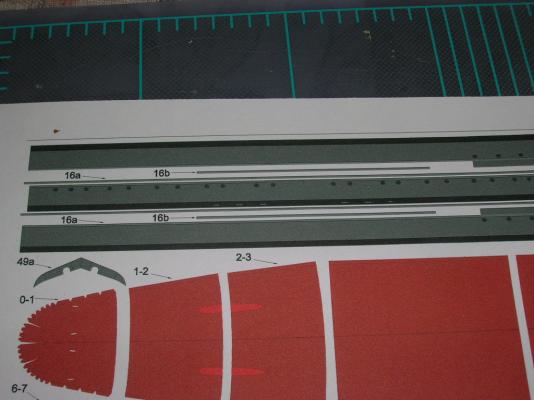
- 37 replies
-
- 2
-
-
- v108
- paper models
- (and 1 more)
-
Intro to Card Models Pt. V: Building V108 - The Hull
ccoyle replied to ccoyle's topic in Card and Paper Models
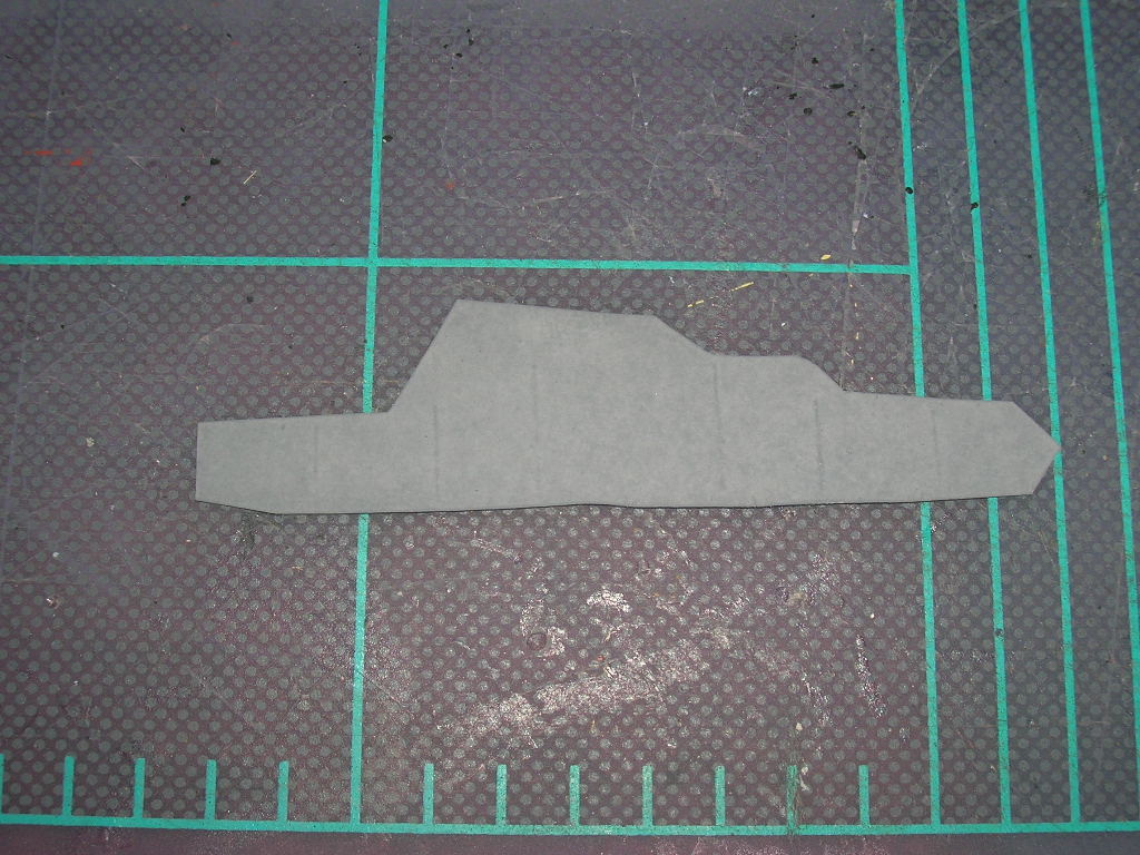
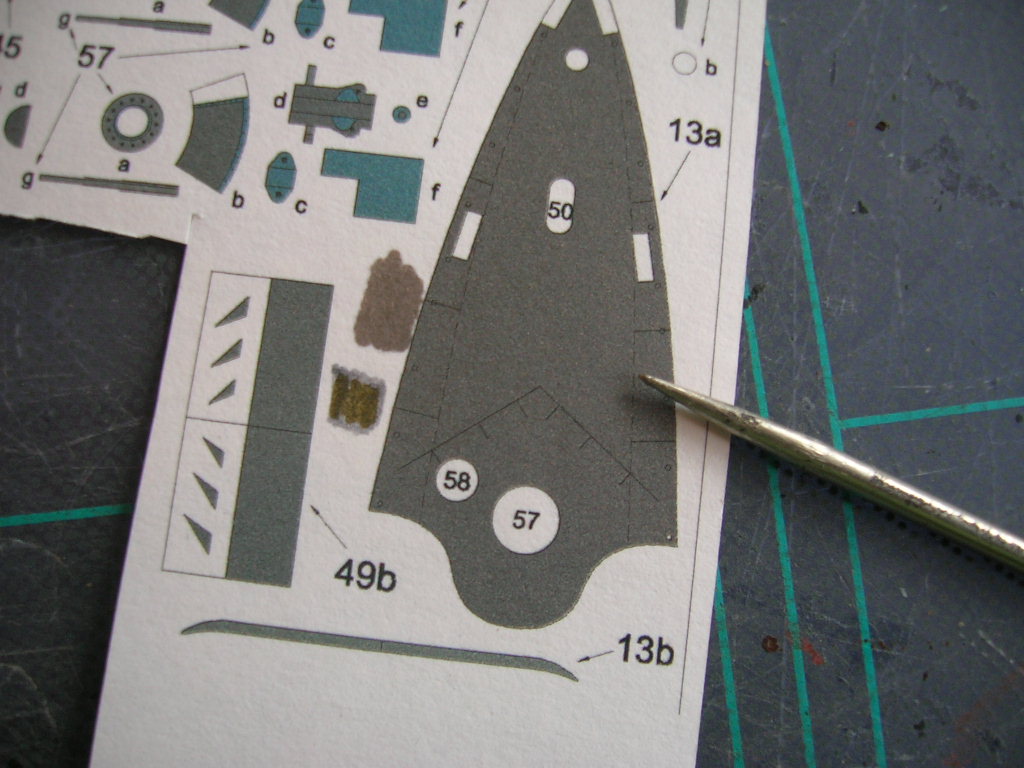
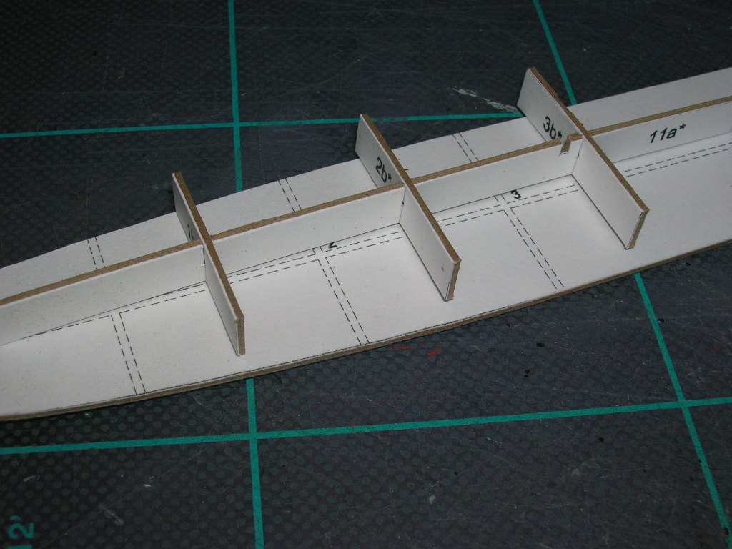
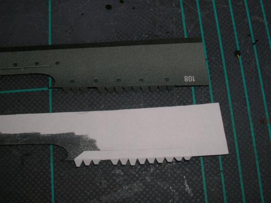
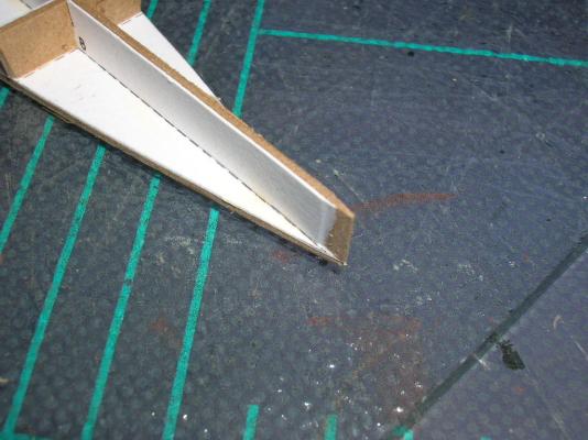
Before we move on to the hull sides, we must first add the forecastle formers. No big deal -- just remember to bevel the bow edge of the longitudinal former. Next it is necessary to introduce another valuable card modeling tool. You will frequently need to fold paper parts, and scoring the fold line makes this job infinitely easier -- the paper will naturally want to bend where the fibers have been weakened by scoring. To do this, you'll want something with a fine but not too sharp tip (you don't want to actually cut the paper). You can do the job with the back of a #11 blade, but I find that an awl or scribing tool works better. Part 13a has two curved, dashed lines on either side that need to be scored. The lines are fairly difficult to see. Straight lines are much easier to score, because you can use a steel rule to guide your scoring tool. Unless you have a set of drafting curves, curved lines will need to be done freehand, and this takes a bit of practice, because paper has a grain, and your tool will thus want to track off to one side or the other. Here's the finished job: Later, the edges of this part will need to formed into a slight curve, but for now you can set this part aside.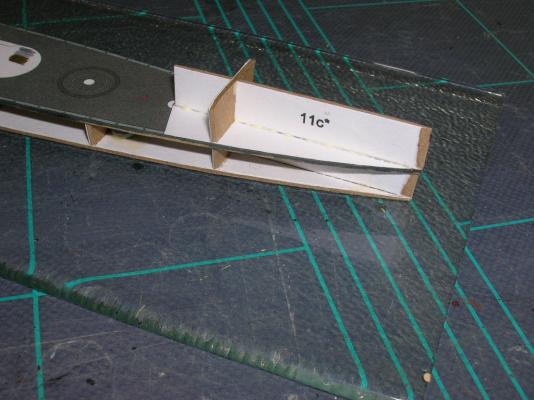

- 37 replies
-
- 4
-
-
- v108
- paper models
- (and 1 more)
-
Intro to Card Models Pt. V: Building V108 - The Hull
ccoyle replied to ccoyle's topic in Card and Paper Models
A vital lesson in card modeling... See anything wrong with this picture? Now this is more how it should be: Spot the difference?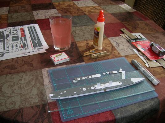

- 37 replies
-
- 6
-
-
- v108
- paper models
- (and 1 more)
-
Intro to Card Models Pt. V: Building V108 - The Hull
ccoyle replied to ccoyle's topic in Card and Paper Models
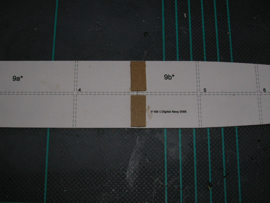
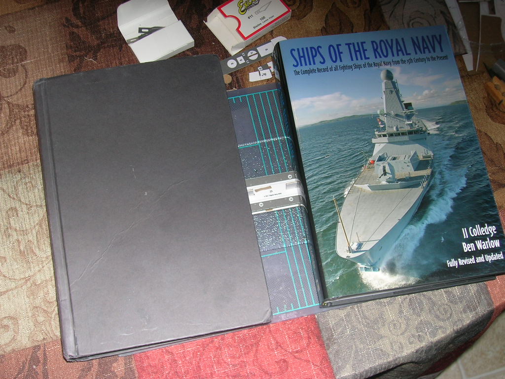
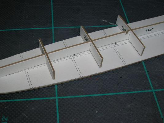
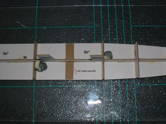
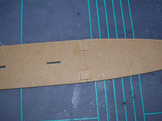
Thanks for your comments, guys! It just so happens I have the next installment ready to go. Once the laminated parts have had adequate time to dry, it is time to start cutting. Here's the complete set of hull framing parts cut from their sheets. Cutting leads right away to a serious question: Do I cut on the line, outside the line, or inside the line? This might seem like a silly question, especially considering that this kit has very fine line borders. However, not all kits have such fine artwork, and (worse perhaps) there is no consensus among designers about whether the line is part of the part or not. Moreover, if you use headband magnifiers while cutting, which I do because of my bad eyesight, you'll discover that even with very fine lines it is possible to cut on, outside, or inside. So, how am I treating this particular kit, you ask? Answer: I tend to cut along the inside edge of the line. Be advised that if you use chipboard, the stuff is like rock compared to ordinary card. My #11 blade tip broke on the second part, but have no fear - the remainder of the blade actually cuts chipboard better without the missing tip (the tip is essential for controlled cutting on plain card, though). In fact, I only needed one blade to cut out all the 1 mm parts. And now we can start gluing! First thing to do is to glue the two halves of the hull base plate together. I'm using Elmer's yellow wood glue -- it grabs pretty fast. Glue the butt joint first, then use two pieces of scrap chipboard to reinforce the joint. Once this is done, it's time to fix the hull base former to a temporary working base -- something rigid that will keep the hull from warping during construction. I use a small piece of plate glass. I used a spot of rubber cement at the bow, midships, and stern. The rubber cement should allow the hull to be easily removed later (hopefully). Next, start dry fitting the hull formers. Remember -- fit twice, glue once! It is important that the bulkhead formers sit flush with the longitudinal former. Trim where necessary. Some of the formers will need to be beveled where they meet curved portions of the hull. The bow end of the longitudinal former will also need beveling. Once all the formers are correctly trimmed, they can be glued to the hull base plate, starting with the longitudinal formers (two parts), then adding the eight bulkhead formers. It is more important that the bulkhead formers are flush with the edges of the base plate than perfectly sitting on the locator lines, but they should be close. Once all the formers are glued in, I add some extra weight to the hull so the finished model will have some 'heft' to it. Here you can see where I've glued in some lead fishing weights. Next comes the main deck. Note that there are some red portions on these pieces -- these are to be cut or drilled out before assembly. I don't worry too much about the drilling, because that is easily done on the assembled hull and isn't always necessary in any case. The cut-out portions, however, should definitely be removed in advance. At this point we may as well talk about edge coloring. Cut paper has edges, obviously, and there are three schools of thought on how to treat these. Some modelers don't color edges; to them, it's a badge of honor of sorts that indicates the model is made from card. Personally, I find uncolored edges ghastly. The second school are those that go to any length to find or mix watercolors, acrylics, or gouache that match the printed colors exactly. These people will also fill and sand any gaps in the seams where necessary. The Poles are masters at this technique, but it is a lot of work. If that floats your boat, go for it. I subscribe to the third school, the one that believes edges should be visually minimized. The idea is to make the seams and exposed edges less obvious but not necessarily completely unnoticeable. Thus, for this model, most any shade of gray felt-tip marker will suffice for edge coloring, since a gray edge on a gray model is far less obvious than a white edge on a gray model. If you go this route, test your markers to make sure they don't bleed excessively into the paper fibers. Once the deck edges are colored, the two halves are glued and reinforced in the same manner as the base plate. Once that's dry, we can then glue the main deck down on the hull formers. Apply glue to the tops of the formers, slip the deck over the two stack profiles that fit through the previously cut out slots, and make sure the tops of the formers are flush with the edges of the deck. Ta-daaaa! Finally, it helps to add some weight on top of the deck while the glue is drying. Here I've added a couple of small but heavy books. That's Ships of the Royal Navy on the right, a perfectly useless book in my opinion, and Retribution by Max Hastings on the left, a much more enjoyable volume chronicling the final year of the allied war against Japan. Till next time!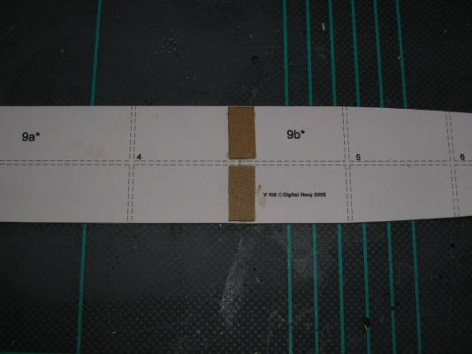


- 37 replies
-
- 5
-
-
- v108
- paper models
- (and 1 more)
-
Chris, You have about 10 degrees C to go before you match the local definition of 'sweltering'. Your Vic is looking great!
-
Intro to Card Models Pt. V: Building V108 - The Hull
ccoyle replied to ccoyle's topic in Card and Paper Models
Yep, Don, good tip on Kinko's. Normal card weights are anywhere from 80-110 lb, so your 90 lb Bristol should work. -
Intro to Card Models Pt. V: Building V108 - The Hull
ccoyle replied to ccoyle's topic in Card and Paper Models
Yes, kit builds all go in the kit build log section regardless of media.