ccoyle
-
Posts
10,605 -
Joined
-
Last visited
Content Type
Profiles
Forums
Gallery
Events
Everything posted by ccoyle
-
 Congratulations, Jesse! Don't let your "Lyme-addled brain" be troubled -- I fixed the title for you. Cheers!
- 1,306 replies
-
- 5
-

-
- syren
- model shipways
- (and 1 more)
-
Great bargain! I hope you will enjoy building it.
-
I agree with the previous posters -- great choice of subject!
-
$20 for a Tamiya kit? I'd be very, very wary! 🤨
-
Very interesting discussion about languages and dialects. I was an exchange student in Ostfriesland. Many of my schoolmates spoke High German as a second language -- just like me. Their first language was Plattdeutsch (Low German).
-
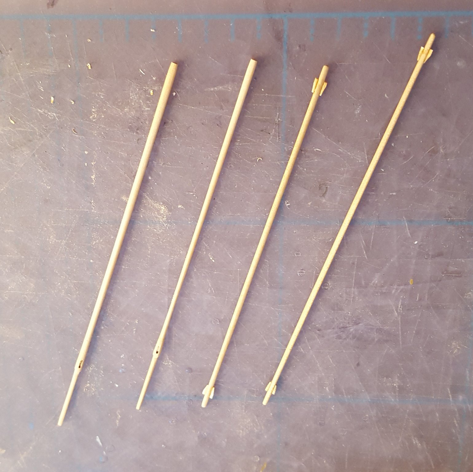
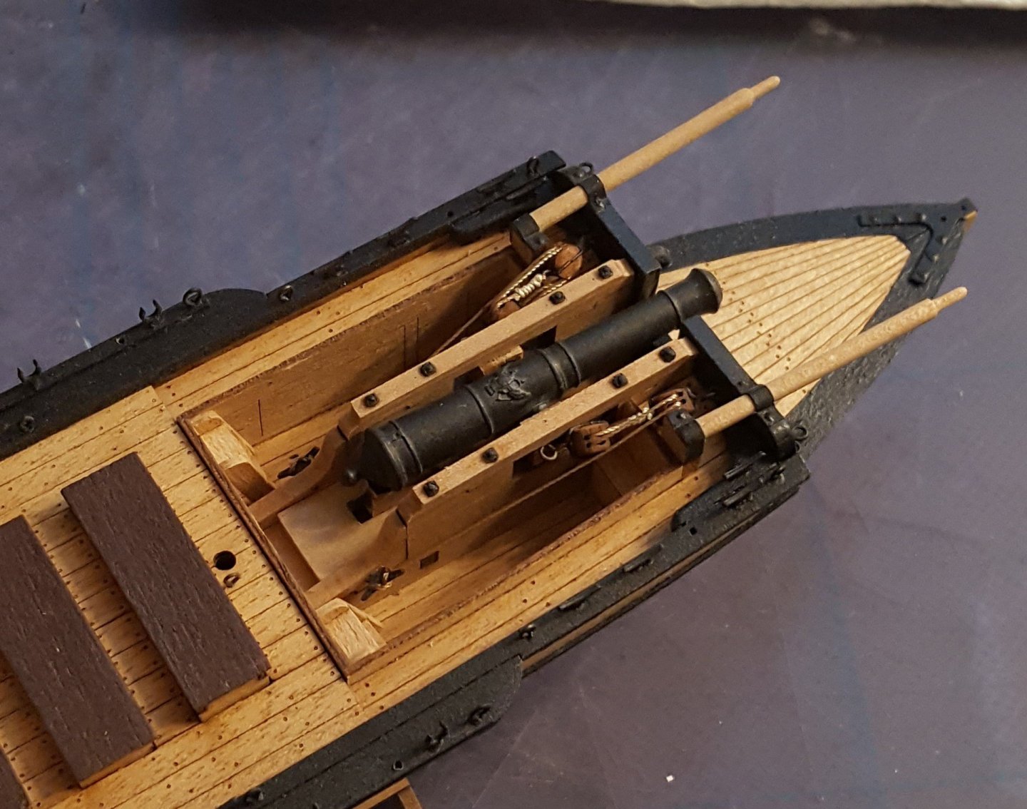
Well, the immediate beneficiary of my X-acto disaster with CGS Canada is the gunboat. Rigged the gun tackles this afternoon. I hope the boys at MK will not mind my saying this too much, but the rigging line supplied in the kit could really stand to be upgraded. However, I'm going to build this with the stuff on hand, so it is what it is.
- 117 replies
-
- 12
-
-
Well, thanks for the interest everyone, but tragedy has struck. While trying to trim a bit of excess card at the top of one hull skin, my steel rule decided to act on its own accord and wander away from the edge being trimmed, with the end result that there is now a long diagonal gash in the hull skin. 🤬 On top of that, I wasn't terribly happy with the way the hull was turning out in the first place. So, I'm setting this one aside for now and going back to the MK Kanonen Jolle, now that I have the corrected rigging table for it. Oh, well ... c'est la vie!
- 10 replies
-
- 2
-
-
- paper shipwright
- canada
- (and 1 more)
-
Still making slow progress; will post a photo or two when I get the hull skins on. Right now I am adding teeny, tiny bulwark stanchions, 72 in total (they are optional parts, but I'm adding them anyway). I can only stand to do about ten at a sitting before I get bored. Forwards!
- 10 replies
-
- 3
-
-
- paper shipwright
- canada
- (and 1 more)
-
ancre La Jacinthe 1823 by guraus - Scale 1:48
ccoyle replied to guraus's topic in - Build logs for subjects built 1801 - 1850
Beautiful work, Alexandru! -
Newcomer looking for help with Cutty Sark rigging
ccoyle replied to Ann's topic in Masting, rigging and sails
Hi, Ann. I merged the two topics for you. Hope you get your answers soon! -
Happy birthday! That's some spectacular scenery there.
- 108 replies
-
- 1
-
-
- armed virginia sloop
- model shipways
- (and 1 more)
-
Que fantastico! Amazing work, Javier.
-
If those few bits at the stern are all that's loose, some of our champion rigger guys should be able to advise you. From here, the rest of the model looks to be in pretty good shape.
-
Virginia Ruth by Kelpie - RESTORATION
ccoyle replied to Kelpie's topic in - Build logs for subjects built 1851 - 1900
Wow! I can't advise you on your project, but what a great story and keepsake! Good luck!- 21 replies
-
- 2
-
-
- virginia ruth
- sloop
- (and 1 more)
-
Certainly! It's not uncommon for members to post logs for already completed builds.
-
Don't rush the decision -- really savor the shopping! And don't panic about the ME sale ending tonight; they have sales all the time.
-
Now I'm thinking that this must surely be one of the older Spanish kits, e.g. Constructo. The issue of a "minor repair" can be ticklish. Of course, it depends on how much work actually has to be done, but generally speaking repair work isn't cheap -- and that presupposes that you can actually find somebody willing and able to do the work. But if the model is otherwise in good shape, re-securing a few loose items, such as lines and blocks, may be something you could do yourself.
-
Good idea -- a shot from directly astern may be a give-away.
-
Bounty is a very popular modeling subject, and a lot of kit manufacturers have offered a kit at one time or another. The contrasting wood colors on your model are typically what one sees in kits coming out of Spain, e.g. Artesania Latina, Constructo, or Dikar (now out of business). Any idea how old the model is?
-
It's funny you should ask, because I was just asking a coworker of mine the same question a couple of days ago. Control-line models were mentioned in one of our products (physics textbook), and I wondered whether high school students today would even know what one was.
-
Ah, now that brought back some memories!