PMG
-
Posts
199 -
Joined
-
Last visited
Content Type
Profiles
Forums
Gallery
Events
Everything posted by PMG
-

HMS AGAMEMNON by PMG - Caldercraft
PMG replied to PMG's topic in - Kit build logs for subjects built from 1751 - 1800
Like George I am always struggling with my guns and gun carriages. The 26 18 pdrs carriage are already made. I just finished the 12 9 pdrs carriages. Now I have to paint them. Like Mobbsie I installed the flintstock on the guns. Not an easy job because the pieces are very very small. I glued them on a toothpick using PVA. Then, I glued them with cyano on the gun and removed the toothpick with a small file. The picture gives an idea. Of course, I didn't make them all. Only 14 18 pdrs but I made all the 9 pdrs. Together, I started the mounting of a carronade (I think that Aggie had 12 of them). I ordered 8 from Jotika. We will see later where to install them. In the meantime, I started with one, and I show you later some pictures. Pierre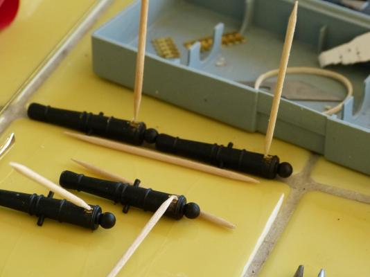
-
Hi Mobbsie, what a beautiful deck! Amazing. Pierre
- 1,279 replies
-
- 1
-

-
- agamemnon
- caldercraft
- (and 1 more)
-
Hi George, welcome in the club! What an impressive progress! And you started only in March? I think your are in a big race with Mobbsie. Lightspeed is the limit... Best regards, Pierre
-
HMS AGAMEMNON by PMG - Caldercraft
PMG replied to PMG's topic in - Kit build logs for subjects built from 1751 - 1800
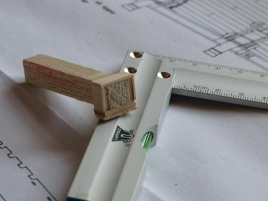
Hello everybody, As you know, I am for a few weeks in the South and there is no question of bringing my ship here. The Admiral should never accept that. I have already to transport her six cats and my dog. You imagine if I had to carry my Agamemnon too. But, I bring with me some "auxiliary" works, such as the boats I made two years ago, and now the 9 pdrs gun carriages. I am attaching here a picture of my "carriage factory", with some very useful tooling. Thank you for all advises I received from you all. But, they are not finished. Next challenge, to install the flintstocks on the guns. I made a first (non succesful) atempt, but when it works, I explain you how I did it... Pierre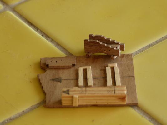
-
That's amazing! Mobbsie, how can you do that all so well and so fast? Pierre
- 1,279 replies
-
- 1
-
-
- agamemnon
- caldercraft
- (and 1 more)
-
HMS AGAMEMNON by PMG - Caldercraft
PMG replied to PMG's topic in - Kit build logs for subjects built from 1751 - 1800
Hello Karin, hello Mobbsie, You are at a point where precision counts, The supplied template is very dangerous... don't use it too much. In the longitudinal direction, there are no big problems, take a good reference line (by exemple the line passing at the beginning of the bulwalk of the quarter deck) and then, make your own template with a sheet of paper. The main issue is to have the correct level. The knowledge of the decks helps and you can check taking into account the height of the guns, but I don't think it's precise enough. There is only one good solution and one good tool that you can check easily against the plans. It is this one: I used it and obtained satisfactory results. I made also templates I used for finishing the ports usinf a file. The calliper sqare is also of daily use... I hope this helps. Now, Mobbsie is right, it should be better if you could start your own build log. It is not difficult to do.
-
HMS AGAMEMNON by PMG - Caldercraft
PMG replied to PMG's topic in - Kit build logs for subjects built from 1751 - 1800
Hello Karin, Thank you for your kind comments, but I think your ship must be very nice too. Photographies should be welcome, of course. Personnaly, you see that I am a very very slow builder. I take my time, but sometimes it can be useful Best regards, Pierre -
HMS AGAMEMNON by PMG - Caldercraft
PMG replied to PMG's topic in - Kit build logs for subjects built from 1751 - 1800
Hello Karin, You are in a difficult situation indeed. As you can see on my picture Nr 002 I bored holes of a diameter of 4mm through the keel. It's not easy to do because the keel is only 5mm wide. You have to bore straight and at the right place. It's, of course, not possible for you to install nuts. If you read the instructions book supplied with the kit, you will see that they mention the boring of the keel at the stage where you are now, it means at the end of the first planking. Of course, without nuts. May be that they mean the use of a sharp pointed screw (and not a screwed bar, as I did). But the fixation will not be so strong, and I think that the ship is rather heavy. You could already start with the boring of 3mm holes. Check carefully the position first. You need three pedestrals and they are not perfectly centered. If you can do it succesfully, without damaging the keel, go deeper. Select the right screw according to the pedestrals you have (if you don't have them, order them first and check then). If you are deep enough you can probably inject some araldite or equivalent to strenghten the assembly, and then, remake a bore with the final screw. Anyway, the screws have to be removable for the continuation of the construction. You absolutely need the bottom of the keel as a reference line. I hope this can help you. Best regards Pierre -
HMS AGAMEMNON by PMG - Caldercraft
PMG replied to PMG's topic in - Kit build logs for subjects built from 1751 - 1800
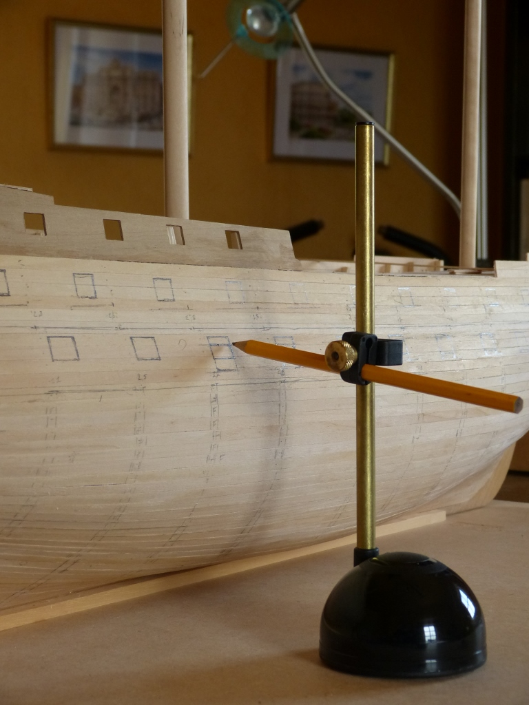
Hello Karin, If you have a look to my pictures Nr 044, 046 and 050 you have a better idea of what I mean. On picture Nr 057 you can see the stand provided in the kit. I covered it with narrow sheets of felt. If I can give you a little advise, it is to be very careful in the positionning and cutting of the gunports. The provided template doesn't help very much. I am still busy to cut them ( that work is now idle for a couple of months since I come back home) and I do an intensive use of a caliper, a water level and a special block caliper I made. It takes a lot of time, but I try to be correct at 0,1mm. Best regards Pierre -
HMS AGAMEMNON by PMG - Caldercraft
PMG replied to PMG's topic in - Kit build logs for subjects built from 1751 - 1800
Hello Karin, I did two things. First, I built the support supplied with the kit . It allows you to work on the ship relatively easily. Second: I broke one end of the first stand. The ship is maintained by the keel but also by one end, either the stern either the bow. Main advantage to use this, is that the ship doens't move too much when you are using it, but, mainly because you have a good and safe reference position. And that will be very very useful later when you will position the gunports, or the waterline, or the wales. It allows to check anytime if your construction is correct against the drawings. I have presently a little problem for sending pictures, but I do it as soon as I can. Best regards, Pierre -
HMS AGAMEMNON by PMG - Caldercraft
PMG replied to PMG's topic in - Kit build logs for subjects built from 1751 - 1800
Thank you Ron, On the Chuck Passaro's website you mentionned, it appears clearly that the front transom is going backwards. I saw it also on several other drawings available on the web or in the litterature. It's not so obvious concerning the rear transom. There, it appears not angled at all. It was probably the Caldercraft intent when they designed the kit. I looked on the 18 pdrs guns and it is the same. However, I didn't realise at that time and I filed them square. Not a big problem, it's almost invisible... However, and sorry Mobbsie, I shall try to make them inclined for the 9 pdrs. Hopefully, I didn't file them already. Thanks again to all, Pierre -
Hi Mobbsie, Leaving the rtched pillars unpainted gives a very good impression. Even more if you lleave the wooden panels unpainted too. Despitely, my pellars are already painted even if I don't foresee to reacg your point of advancement before one or two years... Fantastic progress again. Congratulations, Pierre
-
HMS AGAMEMNON by PMG - Caldercraft
PMG replied to PMG's topic in - Kit build logs for subjects built from 1751 - 1800
Thank you Mobbsie, for the advise. Filing will not be a problem, of course. But, I wondered if I was missing something. Pierre -
HMS AGAMEMNON by PMG - Caldercraft
PMG replied to PMG's topic in - Kit build logs for subjects built from 1751 - 1800
Hello all mates, I recovered my photography size reduction system and can so go on. I started the 9 pdrs gun carriages. And I wondered that the notches at the bottom of the carriage were not square. I didn't notice that when making the 18 pdrs gun carriage. Is that just an imprecision in the laser cutting or is it intensionnaly done? The drawings are giving no precise answer at the question. When looking at several gun carriage pictures I noticed that very often the internal pieces are inclined backwards. In conclusion, I suppose that I have to do it also. Does somebody have an advise on the question? Here is a picture illustrating the subject. I am not sure it is clear enough. Pierre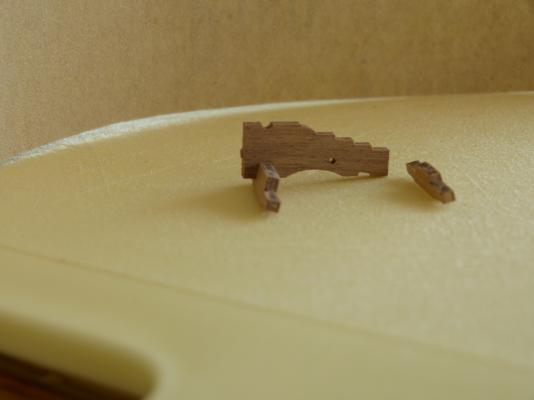
-
HMS AGAMEMNON by PMG - Caldercraft
PMG replied to PMG's topic in - Kit build logs for subjects built from 1751 - 1800
Hello Anja, Thank you for the kind comment. Albert II is a very special man, very "belgian" and a great king. Philip, I had the opportunity to meet a couple of times, will surely be a good king too. Our two kingdoms have now, in a short time, two new kings. Long life to them. I am now back in my "southern" house for a certain time. We prepare the garden and the house for the summer. At the end of the week our children begin to join us for some weeks holiday. That's , of course, not a good news for my Agamemnon staying in the "North". However, I brought with me some things, like deck furniture and guns to do. Presently, I have a problem to reduce the size of my pictures, so I cannot send any. At the end of the week , my son who is computer specialist is arriving and will surely arrange that. Greetings, Pierre P.S.: But, here, in the South, I have a "secret weapon".... A kit, I bought in Spain 25 years ago, almost for nothing. May be , I could start a new build log about because I made photographies. -
HMS SERAPIS by PMG - Aeropiccola
PMG replied to PMG's topic in - Kit build logs for subjects built from 1751 - 1800
Thanks to all friends for the comments and precious advises. I will take these plates off and place new ones once the hull is completed. The old ones, I have 800 or 900 of, will be used, later on another (future?) ship. Pierre -
HMS SERAPIS by PMG - Aeropiccola
PMG replied to PMG's topic in - Kit build logs for subjects built from 1751 - 1800
Thank you for the advise, Steve. Anyway, if I don't find other drilled plates like the originals (they are nice, but I I think there are none to find anymore) I will be obliged to choose another solution. Thanks again, Pierre -
HMS SERAPIS by PMG - Aeropiccola
PMG replied to PMG's topic in - Kit build logs for subjects built from 1751 - 1800
I made an attemps with my small drilling machine. But, the holes gave a diameter of 0,5 or 0,6 mm. And if they are not perfectly in line, the effect is very poor. The accuracy of my machine is not sufficient to guarantee such an alignment. And with 0,5 or 0,6 mm drills, I expect a high rate of attrition... I think, I shall put all new plates from Jotika. But I shall do it later, after a succesful trial on my Agamemnon. Pierre
-
Hello Mobbsie, As usual your progress is impressive, even if you face some problem from to time. But you solve them, of course. Congratulations, Pierre
- 1,279 replies
-
- 1
-
-
- agamemnon
- caldercraft
- (and 1 more)
-
HMS AGAMEMNON by PMG - Caldercraft
PMG replied to PMG's topic in - Kit build logs for subjects built from 1751 - 1800
Hello Karin, I send you here two more pictures of the rabbett plank. This plank has to be positionned very carefully and sone bevelling is necessary. But, once it has been done, the effect is really very nice. On another and, if you decided to place your finished ship on small columns, it is more than time to think to. Here is a picture of what I did. I am now always busy to shape the lower gundeck ports. I made a small calliper. Very usefull and absolutely necessary to make a clean job. Size: a little bit less than 15 x 17 mm and do not forget to round the corners. Also interesting: the square longer part. You can place a bubble level to check that your gunports are parallel to the keel. Greetings, Pierre


-
HMS SERAPIS by PMG - Aeropiccola
PMG replied to PMG's topic in - Kit build logs for subjects built from 1751 - 1800
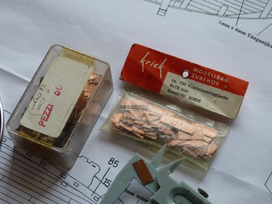
Here is a better (I hope) picture of the plates. Their size is 8mm x 18 mm. You can perhaps see that they are bordered by small holes. These holes doesn't seems to have been made by punching as there is no protuberation at all. Apparently they are drilled, but I wonder. I did an attemps to make them myself. I therefore bought thin copper plates (0.5 mm thick) from a printer. In the old time, printers (the man not the machine) were using thin copper plates. I cutted in slices. Not very easy. But finally, I stopped because I found myself totally unable to drill the holes in straight line following the requested pattern. I saved these plates for places like the rudder and may be the keel. I already told that the glue I used was absolutely not the right one. I will so be obliged to remove all the plates. I wonder if, in such a case, the best should not be to by a new set (by Jotika for example) and redo all the job. Pierre


-
Hi Christian, I hope all is OK with your linguistic examination. I did it (for the defence) 25 years ago and it is not considered as easy. At the time 40% of the people only did it with success. Fortunately, I had no problems and I hope it will be so for you too. It's true, there is apparently a lack of Belgian model shipbuilders, or shipbuilders wanting to share their experiences and problems. Pierre
-
HMS AGAMEMNON by PMG - Caldercraft
PMG replied to PMG's topic in - Kit build logs for subjects built from 1751 - 1800
Hello Karin, I started also the first planking from the deck. There is not very much question about because the 4 or 5 first planks run well parallel and they don't need to be reduced at one or another end. The only difficulty is to make the short radius at the bow. I continued to work (from the top) with "packages" of 5 or 6 planks taking as reference a plank (the 6th) I fixed as naturally as possible to avoid if possible any strains. It was also easy to calculate (step by step) the reduced width at the bow and at the stern. The following picture is giving an idea of what I did. On another way, I calculated that the total hull development was a normal multiple of the plank width (where the hull is the biggest, of course). So, I found it should be a pitty to be in trouble when arriving at the rabbet line from the desk. The 4 or 5 first planks from the rabbet founf easily their position, without forcing and without reducing their width at neither extremity. I decide so to place these 4 or 5 planks founding so naturally their position, leaving for later the matching. Actually, the matching of the planks coming from above and from beneath was much more easy than expected. I hope this can help. If you want, I can post other pictures. Greetings, Pierre
-
HMS SERAPIS by PMG - Aeropiccola
PMG replied to PMG's topic in - Kit build logs for subjects built from 1751 - 1800
I forgot to tell you that HMS SERAPIS was the first ship of that size to come coppered out of the shipyard. Coppering was not foreseen in the kit. Around 30 years ago I found in an hobby shop in Ostend some very nice copper plates with small holes to put nails in. But I got only 100 of. later, I found another 100. Finally, I found in Como (Italy) a box of 500. But it is still not enough. On the first pictures of my Serapis you can see my first attempt of coppering. I used contact glue for. But, with the time, it appeared not to be the right choice. Now, I don't know what I will do. If I cannot find more of the original plates I will be obliged to change and redo the job. That's will be for later... Pierre