
MORE HANDBOOKS ARE ON THEIR WAY! We will let you know when they get here.
×


KeithAug
-
Posts
3,867 -
Joined
-
Last visited
Reputation Activity
-

 KeithAug got a reaction from Tecko in Altair 1931 by KeithAug - FINISHED - Scale 1:32 - schooner
Thanks Pete
I stayed at Coeur d'Alene once on the way to visit the Scablands and Glacier NP. A nice part of the world.
Progress of a different kind!
Having glued the deck in place and strengthened the areas unsupported by frames (g clamps in photo), I thought I had better take stock.
For the deck edge planks I needed to cut .040" x .130" mahogany strips from a 40"x12"x7/8" former table top. This involved planing and sawing operations on my full size wood machines as well as sawing on the Byrnes saw using TCT and slitting saw blades. Multiple operations and setting on different machines is always something I am inclined to put off. This instance was no different and I found myself looking for something else to do. My diversion project started out as cleaning up the workshop (photos attached) but very quickly expanded into clearing out my tool draws. I set myself the challenge of throwing out all the tools that I couldn't remember having used in the last 20 years. It was quite a haul but I failed with a few items that I thought might come in useful some day!!! They will probably be thrown out by the kids when they come to sort out my affairs in another 20 years time. The up side though is that I discovered stuff that would be useful if I had only remembered that I had it.
Having exhausted all my diversionary jobs I made the 6 deck edge planks, yawn!
I have a question for all you experienced posters. I see that when you sign off your posts you frequently attach reference to all your past, ongoing an future builds. I assume that you don't type this stuff out every time and that somehow you have set it up automatically. How do you do this please?
Keith
-
KeithAug got a reaction from Tecko in Altair 1931 by KeithAug - FINISHED - Scale 1:32 - schooner
The sub deck:-
The various apertures for the chart house, skylights, hatches etc were cut out using a craft knife before
hacking the deck roughly to shape using the jigsaw. I left about 1/8 inch all round for final adjustment. A prolonged process of plane a bit, pin in place, check, remove, plane a bit more then ensued until I was happy with the fit. With the sub deck in place I drilled through it into the frames at multiple positions. As explained earlier the deck is concave longitudinally and convex across the beam. Some force is needed to hold the shape while gluing and the multiple holes will take the holding pins during in the gluing operation. The photos show the deck temporarily in place.
I mentioned in a previous post that the frames were spaced randomly on the plan and I had thought that this was for some greater purpose - to be revealed later in the build. It would have been sensible if the frames had been organised around the deck apertures but this wasn't the case - so the mystery of the random spacing continues.
With the deck temporarily in pace I marked the aperture positions on the frames and then removed the deck and cut the frames away with a razor saw. In one position I reinstalled an offset deck beam to support the deck. In two other positions I intend reinforcing the ply to compensate for local removal of the frames. I decided to install 2 oak blocks threaded and tapped (M8) to take the bolts for later installation of plank to handle the hull inverted for the 2nd planking operation. I find oak takes a thread well and shows no tendency to strip.
Finally I marked the edge of the deck on the line where the mahogany deck planks meet the teak planks.
Nothing to do now but glue the deck.
-
 KeithAug got a reaction from KORTES in Altair 1931 by KeithAug - FINISHED - Scale 1:32 - schooner
Removal of up stands and a start on the deck:-
I had part cut the frames at deck level so removal of the up-stands wasn't a difficult process. I started by hand cutting but soon abandoned this in favour of a recently acquired multi tool fitted with a plunge blade. It worked a treat and I wonder why I hadn't bought one ages ago. I sanded the frames until I was comfortable with the deck profile which is concave bow to stern and convex across the beam. I used one of the left over planks laid across the frames to test the deck shape.
I decided to make the sub deck from 1/16 inch ply. Having cut a rectangular piece large enough to cover the hull I laid one of the long edges on the centre line of the hull and marked the position of the frames. I then drew the frame positions across the ply.
Having established the frame positions I used dividers to transfer the shapes of the deck cut outs from the plans on to the plywood.
Again using dividers I transferred the width of the hull on to the plywood at each frame position. The frames width dimensions were taken from the actual hull and not the plans.
I then used pins to give reference points against which a plank could be bent enabling the deck edge profile to be marked.
Having marked the deck profile I temporarily attached the plywood to the hull along the centre line.
I then marked the hull profile on the underside of the plywood using the hull as a template - thus checking the accuracy of the deck profile previously drawn. All was well.
Keith
-
 KeithAug got a reaction from Nirvana in Altair 1931 by KeithAug - FINISHED - Scale 1:32 - schooner
A little more progress..........
Having marked the waterline on the hull I realised my previous sequence had missed the vital step of making a building cradle. I had a look around the workshop and came across the discarded cradle from Endeavour. The fuller hull of Altair was fortuitous as a few quick cuts with the jigsaw transformed the cradle into one suitable for this build. (I used the frame templates from earlier to get the correct cradle profile).
With the hull finally the correct way up I set about the task of removing the building board. You may recall not all the frames were glued to the board and I had marked the glued frames so I knew where to cut.
While cutting away the building board I mused on the various removal stages and decided to name them for fun:-
1 THE AIRCRAFT CARRIER STAGE. (Illustrious class I think)
2 SAWING THE FAT LADY IN HALF STAGE. (Taking care not to get carried away)
3 THE CHINESE JUNK PHASE.
4 THE GALLEON PHASE (Forecastle still to be built)
Having removed all of the building board I started on the frames - the aft most frame removed to deck level.
-
KeithAug got a reaction from KORTES in Altair 1931 by KeithAug - FINISHED - Scale 1:32 - schooner
Having completed and finish sanded 1st planking I had a few things to sort out about future stages. After some thought I decided on the following sequence:-
1 Drill the hole to take the prop shaft.
2 Mark the waterline.
I wanted to compete items 1 and 2 while the hull was still attached to the building board - so that I had a reference datum for the 2 operations.
The sequence continues with:-
3 Remove the hull from the building board.
4 Trim the frames to size at deck level.
5 Mount the 1/16th inch ply sub deck, with cut outs for the deck house, skylights and hatches.
6 Plank and finish sand the deck.
7 Mount the 3 layers of 1/32 inch ply which form the bulwarks and the sculpturing of the hull sides.
8 2nd plank the hull. (Having manufactured the planks from mahogany).
This lot should take care of the next few months.
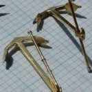
Staring with the prop shaft which is asymmetric - sitting on the port side of the hull.
The prop tube is 3/8 inch diameter, angles downwards at an angle of 6 deg and outward from the centre line at an angle of 8.5 degrees. See Photo.
I didn't feel comfortable trying to drill this by eye, so I manufactured a simple jig consisting of 2 parallel MDF boards, separated by 3 inch, drilled with offset holes the alignment of which gave the compound angle necessary for drilling. I did have to revert to a bit of school room trigonometry which taxed the brain cells more than I expected (a bit worrying). See Photo.
Having positioned the jig so that the drill intersected the hull at the correct point I then clamped it in place and drilled the hull with a 3/8 inch by 18 inch long auger drill. To keep things under control I took my time and hand drilled using a woodworking brace. The photographs illustrate the procedure.
-
KeithAug got a reaction from KORTES in Altair 1931 by KeithAug - FINISHED - Scale 1:32 - schooner
I have now completed the 1st planking on both sides of the hull - so far so good. Although I had thought that I would revert to narrower planks at some stage, in the end I found it to be unnecessary.
Before sanding I roughly drew pencil lines on the hull to act a sanding guide. Sanding to remove the pencil lines enables me to achieve a smooth finish while avoiding sanding through of the planks.
I have completed the sanding of one side - it took about an hour and a half using coarse grit emery cloth on a cork block.
The bow and stern shots show the before and after.
I have abandoned sanding - family are arriving soon and they plan to stay for at least a week. Boat building has to be curtailed for some time.
-
KeithAug got a reaction from KORTES in Altair 1931 by KeithAug - FINISHED - Scale 1:32 - schooner
Hi Pete, John and HArtmut. Thanks for your encouragement on my planking efforts.
Its time for a progress update.
I thought I would get the difficult bit out of the way and continue with the tapered planks around the hulls belly. The photos are fairly self explanatory so I'll cut down on dialogue.
The final closure plank is always the most tricky to get right and I have developed the "black finger method" to make it easier.
I start by loosely laying a piece of printer paper over the hole to be filled. Running a finger over the paper above the hole creates an indent which accurately represents the shape of the closure plank.
I find it really hard to see the profile of the plank once the paper is removed so I shave some graphite from pencil and rub my finger in it.
I then rub my finger over the paper and this gives me a very visible profile for the closure plank.
I then cut out the profile to make a template.
The template is transferred to a plank and glued in place using a glue stick.
The plank is cut out, finish sanded to fit and then glued in place.
Now I can proceed with the easier task of planking the keel.
-
KeithAug got a reaction from Nirvana in Altair 1931 by KeithAug - FINISHED - Scale 1:32 - schooner
Hi Pete - thanks for the positive feedback.
1st Planking the hull continues. After completing 9 parallel planks the curvature was getting a little excessive so it was time for a change in strategy. I started looking for a natural plank line and then dithered for hours wondering which line would be best. After drawing many options on the hull I decided to be undecided and just ploughed on regardless - reasoning that I'd make the best of whatever line I chose. I marked a line using a stiff plank and used pins to form location points for positioning the first of the next stage of planks.
Having marked out the plank line on one side of the hull I used dividers to transpose an identical line on the other side of the hull. So far the planking on either side of the hull is identical and I want to keep it this way - silly really as it will be over planked. (My OCD kicking in again).
I have now completed 3 of the new phase of planking and all is well - so far!!!
-
 KeithAug got a reaction from jlefever in Altair 1931 by KeithAug - FINISHED - Scale 1:32 - schooner
The deck (and hence the hull top line) has a significant bow from stem to stern. I therefore decided not to try and follow the deck to hull intersection with the 1st plank. Also the first plank was being laid at a small distance from the hull / deck intersection to take the later installation of the bulwark.
The line of the 1st plank was marked using a flexible straight edge which I made from .060 inch plastic.
Having marked the line I placed a number of pins along it to act as stops against which to accurately locate the 1st plank. The first plank was then installed using PVA wood glue and held in place by notice board pins while drying.
At .060 inch thick the first plank wasn't as flexible as I would have liked and so I decided to thin down succeeding planks progressively thinning each plank by .002 inch (reducing the planking thickness .050 inch by the 6th plank). Another departure from a previous post is that I found that I only had .250 inch x 3 inch x 48 inch obechi. I ordered up some .200 inch but decided to progress the planking using what I had. I will revert to the narrower planks where the hull curvature becomes more pronounced.
The first 5 rows of planking have gone on well and I haven't felt the need to do any tapering thus far.
The natural flow of the 1st plank left the stern in need of additional planks and before proceeding with the stern I marked a straight edge for the uppermost (nearest the deck) plank. I checked that the line for the upper plank was identical on both sided of the hull using my improvised height gauge (on the right of the picture)
I then installed the top plank on each side.
I then infilled the remainder of the stern using tapered planks.
-
KeithAug got a reaction from KORTES in Altair 1931 by KeithAug - FINISHED - Scale 1:32 - schooner
Experiments with Planks.
For a while I have been thinking about planking the hull. In particular I have been considering how to go about creating the sculptured lines on the bulwarks. See Photo
I think I am going to overlay 3 layers of 1/32 (.031) inch ply to create the effect and this means the planking thickness will need to total 3/32 (.094) inch (to avoid a step where the ply meets the planks).
The outer mahogany planking on Endeavour was .020 inch thick by .160 inch wide - basically a veneer. It had the advantage of shaping easily but I was very nervous that I would rub through when finish sanding. In the event I din't rub through but I can't help thinking I was lucky. For Altair I thought I needed to go thicker.
Mulling things over I decided to 1st plank with bass or obechi planks .060 inch thick and .200 inch wide and 2nd plank in mahogany .031 inch thick and .200 inch wide.
The challenge of accurately cutting the mahogany second planks (which I haven't done before) prompted a bit of experimentation. The mahogany I am using is about 100 years old, beautiful stuff but a bit brittle. I ripped the 1 inch thick plank down to .200 inch thick using the carbide blade supplied with my Byrnes saw. I then switched to a 1/32 (.031) slitting saw blade to cut the .031 inch thick planks. The set up of my saw (which is a bit unusual) is covered in the attached series of photos.
The experiment was a success. I cut 3 test planks and all were .031 +/- .001 inch. I am now feeling confident about going into mass production.
-
KeithAug got a reaction from KORTES in Altair 1931 by KeithAug - FINISHED - Scale 1:32 - schooner
I thought it would be interesting to compare the hull with what Endeavour looked like at this stage. I have done a better job with balsa backing Altair. Endeavours frames however show the greater uniformity of shape. Laser cutting of frames on a mass produced kit clearly has advantages over not so well drawn jigsaw cut frames.
-
KeithAug got a reaction from KORTES in Altair 1931 by KeithAug - FINISHED - Scale 1:32 - schooner
Much sanding - but now complete. It took about half a day per side using 60 grit emery cloth attached to my home made sanding block - in one of the pictures. The reshaping of some of the frames (mentioned earlier) proved to be necessary. Marking the edges of the frames was very helpful as a sanding guide and the sanded hull passed the "hand undulation check". The frames in the area of the hull at the top of the rudder proved to be incorrectly shaped and i will sort this out prior to 1st planking. I have attached a photo of the real thing to show what I need to reproduce.
-
 KeithAug got a reaction from PeteB in Altair 1931 by KeithAug - FINISHED - Scale 1:32 - schooner
Balsa Infill Prior to Planking
I find infilling between frames with balsa eases the planking operation. Also I quite enjoy the process as it’s a bit of a challenge creating the 3 dimensional shapes necessary to nest between frames while conforming to the profile of adjacent infill pieces. All the balsa is ½ inch plank 3 inches wide by 18 inches long. I needed 12 planks to complete the hull – cost me £12 on ebay.
I use a disc sander for shaping – mine has been modified to take the miter gauge from my Byrnes saw. A simple and cheap way of getting an acceptably accurate disc sander.
Having completed the rough fairing of the frames I re-marked the edges of the frames with the felt tip pen. This would give me the guide for final sanding once the balsa infill was complete.
I find filling alternate frame gaps with balsa has the benefit of allowing me to progress while the previously completed and glued balsa infill dries (I use a PVA wood glue). Also at this stage I roughly shape the infill using a rasp leaving about 1/16 inch of balsa proud of the adjacent frames – for final finishing with sandpaper.
I then infill the remaining frame gaps before finishing the rough shaping with the rasp.
-
KeithAug got a reaction from PeteB in Altair 1931 by KeithAug - FINISHED - Scale 1:32 - schooner
Frame Adjustment & Fairing
Having done the test assembly I did the usual plank check by laying a .040” by .200” plank along the length of the hull and looking for high and low spots. The significantly oversized frames were marked with a green felt tip and the significantly undersized frames were marked in pink. By significant I mean a deviation of between .040 and .080 inches. See Photos.
The oversized frames were easily adjusted using disc sander while the undersized frames had to be built up by bending and gluing .040 strips of wood around the frame edges.
Having got the frames about right I then glued up the skeleton of the yacht. Only 4 of the frames were glued to the building board to ease removal at a later date. Because all frames were positively located in building board the gluing of 4 frames proved sufficient to create a very rigid assembly.
After gluing I used a felt tip pen to colour the edges of all the frames. I do this as I find it gives a very good guide when sanding to fair the frames. By watching where the felt pen is removed during sanding I am able to duplicated the fairing on both sides of the hull and ensure that that the blending of the hull lines is uniform. I take my time while sanding and frequently check the form of the hull using the previously mentioned flexible plank. See photos.
-
KeithAug got a reaction from Tecko in Altair 1931 by KeithAug - FINISHED - Scale 1:32 - schooner
Keel and building board
A bit more progress fitted in around various DIY jobs. I transferred the keel shape to card that I the stuck to the ¼ inch ply before more jigsaw work. See Photos.
I made the building board from ¾ inch thick 6 inch wide MDF. For about 2/3 of the length of the hull the building board is double thickness with the stand off for the frames reduced in height to compensate (reducing plywood wastage). Using my router table I machined slots along the length of the MDF to facilitate:-
1. accurate alignment of the 2 boards
2. location of the frames along the center line
3. location of the board on the milling machine to cut slots for the frames at right angles to the center line.
The frame spacing was accurately measured from the plan and I used the digital read out on the mill to accurately set the positions for the frame sots. None of the frames were equally spaced which was a bit of a bind.
The photos should illustrate the process.
Finally I did a test assembly of the frames to give myself a feeling of progress.
Everything fitting together well and all right angles accurately made .......... feeling very content!
-
 KeithAug got a reaction from Andrea Rossato in Altair 1931 by KeithAug - FINISHED - Scale 1:32 - schooner
Frames finished (23 in all)
Having cut out the frames I stacked them and did an eyeball check on how well they nested. All seemed to be sensible with the exception of frame 8 which was noticeably too narrow by about 3/16 of an inch. I assumed that I had marked it out incorrectly so rechecked it against the plans. It turned out that I had marked it out correctly and the frame drawn on the plan was incorrect. The frames on the plan are all individually drawn rather than the normal convention of overlaying all hull lines on a single image. The latter approach would of course have revealed the error during the draughting of the plans. I corrected the problem by widening frame 8 with strips of wood on either edge and then sanded by eye using frames 7 and 9 as guides. See Photo.
I used the jigsaw to cut through about 80% of each frame at deck level to ease removal of the building board up-stand later in the build.
I then stacked all frames to satisfy myself that the transitions between frames seemed logical.
-
KeithAug got a reaction from KORTES in Altair 1931 by KeithAug - FINISHED - Scale 1:32 - schooner
Keel and building board location slots.
The important thing here is that the keel and building board slots are accurately cut to width and that they are in perfect alignment with one another. I did consider cutting them freehand but decided to try and find a way of slotting them out accurately on the mill. The slots needed to be ¼ inch wide to match the ply that I intended using for the keel.
I started by making a jig for drilling - see photo. With this I drilled holes at the inner end of the location slot in all the frames. By drilling trough the frames and the jig I created a position for a location peg (1/4 inch diameter) which meant I could accurately reposition the frames to drill the ¼ inch holes at the end and at interim positions in the keel slot.
I should explain that I am drilling using a mill with an x/y table. I am keeping the y setting locked and only varying the x setting to accommodate the different positions of the keel slot. I am therefor ensuring that all the drilled holes are in alignment and at right angles to the building board edge of the frame.
To cut the slots accurately I decided to use a slitting saw mounted in the mill. My first operation was to mount a piece of wood vertically in the mill vice. I then locked the mill spindle and machined off the upper edge of the wood using the slitting saw, thus ensuring that the saw cut relative to the wood was the same for all subsequent cuts. See Photo.
Using the ¼ inch holes in the frames with a pair of location pegs I then clamped the frames to the wood with the pegs tight against previously cut surface. Once clamped the pegs were removed. With the slitting saw (still locked in its preset vertical position) I then cut one side of the keel and location slots (obviously two cuts from opposite ends). See Photo. I then unclamped the frame reinserted the dowel pegs flipped it over re-clamped and repeated the cuts as before. Result! – accurate ¼ inch keel and location slots perfectly aligned.
-
KeithAug got a reaction from PeteB in Endeavour 1934 by Julie Mo - Amati - Scale 1:35 - America's Cup UK J-Class Challenger
Julie - I prefer to get it right - even though it will be hidden by the second planking - but many will revert to epoxy filler and as it won't be seen it will look fine.
Here is how I did it.
Firstly I didn't start at the bulb. If you work up to the bulb at least you have something to but the bulb planks up to. Here is how I did it.
I planked from the deck towards the keel until it started to become apparent that the bow profile needed to start transition from sharp to a rounded form. At this point I laid the first 3 bulb planks along the keel. One central, plus one either side.
All the keel planks need to be shaped into a trapezoidal shape and I did this by sanding using a sanding jig that I made. This was a piece of oak with a 2mm wide 1mm deep slot cut along its length. The 2mm x 2mm keel strips were place in this slot and the protruding 1mm was shaped by sanding along its length and at an angle to the surface of the oak. If you have a violin plane this might be better than sanding. The oak plank had other slots of differing thicknesses to take other planks.
I progressed with the hull planks until once again it seemed that the rounded form of the bulb needed to be fuller - I then laid the next 2 planks along the length of the bulb.
I continued in this manner until the hull and the bulb planking was complete.
My feeling was that my method was better than that suggested in the instructions.
-
 KeithAug got a reaction from Eddie in Endeavour 1934 by Julie Mo - Amati - Scale 1:35 - America's Cup UK J-Class Challenger
Julie - I'm please to be able to assist. There is a lot of relevant 1st and 2nd planking detail in my current build if you are interested - Altair - see below.
-
KeithAug got a reaction from Eddie in Endeavour 1934 by Julie Mo - Amati - Scale 1:35 - America's Cup UK J-Class Challenger
P.S.
Julie looking at the back of your keel it looks quite consistent in thickness. Mine had a waist - see photo.
-
KeithAug got a reaction from Eddie in Endeavour 1934 by Julie Mo - Amati - Scale 1:35 - America's Cup UK J-Class Challenger
Julie - I prefer to get it right - even though it will be hidden by the second planking - but many will revert to epoxy filler and as it won't be seen it will look fine.
Here is how I did it.
Firstly I didn't start at the bulb. If you work up to the bulb at least you have something to but the bulb planks up to. Here is how I did it.
I planked from the deck towards the keel until it started to become apparent that the bow profile needed to start transition from sharp to a rounded form. At this point I laid the first 3 bulb planks along the keel. One central, plus one either side.
All the keel planks need to be shaped into a trapezoidal shape and I did this by sanding using a sanding jig that I made. This was a piece of oak with a 2mm wide 1mm deep slot cut along its length. The 2mm x 2mm keel strips were place in this slot and the protruding 1mm was shaped by sanding along its length and at an angle to the surface of the oak. If you have a violin plane this might be better than sanding. The oak plank had other slots of differing thicknesses to take other planks.
I progressed with the hull planks until once again it seemed that the rounded form of the bulb needed to be fuller - I then laid the next 2 planks along the length of the bulb.
I continued in this manner until the hull and the bulb planking was complete.
My feeling was that my method was better than that suggested in the instructions.
-
 KeithAug reacted to Julie Mo in Endeavour 1934 by Julie Mo - Amati - Scale 1:35 - America's Cup UK J-Class Challenger
Thank you, once again, Keith!
The sanding jig looks like the way to go.
I will also have to start from the deck, like you did, and work my way down. I first need to find the push pins I bought. Or buy some new ones. Rubber bands don't seem to work so well in keeping the hull planks in place.
-
 KeithAug got a reaction from Canute in Endeavour 1934 by Julie Mo - Amati - Scale 1:35 - America's Cup UK J-Class Challenger
Julie - I prefer to get it right - even though it will be hidden by the second planking - but many will revert to epoxy filler and as it won't be seen it will look fine.
Here is how I did it.
Firstly I didn't start at the bulb. If you work up to the bulb at least you have something to but the bulb planks up to. Here is how I did it.
I planked from the deck towards the keel until it started to become apparent that the bow profile needed to start transition from sharp to a rounded form. At this point I laid the first 3 bulb planks along the keel. One central, plus one either side.
All the keel planks need to be shaped into a trapezoidal shape and I did this by sanding using a sanding jig that I made. This was a piece of oak with a 2mm wide 1mm deep slot cut along its length. The 2mm x 2mm keel strips were place in this slot and the protruding 1mm was shaped by sanding along its length and at an angle to the surface of the oak. If you have a violin plane this might be better than sanding. The oak plank had other slots of differing thicknesses to take other planks.
I progressed with the hull planks until once again it seemed that the rounded form of the bulb needed to be fuller - I then laid the next 2 planks along the length of the bulb.
I continued in this manner until the hull and the bulb planking was complete.
My feeling was that my method was better than that suggested in the instructions.
-
KeithAug got a reaction from Canute in Need Copper Plating for Amati Vanguard - HELP!
Glenn
Cornwall Model Boats sell Amati plating - http://www.cornwallmodelboats.co.uk/acatalog/amati-copper-plates.html. But it seems to me that if you had little waste you should expect more to be supplied free of charge.
-
KeithAug reacted to glbarlow in Need Copper Plating for Amati Vanguard - HELP!
Keith, Thank you for the link. I had searched Cornwall's site and failed to locate the copper plating. With your link I was able to place the order, I appreciate it!