xken
-
Posts
841 -
Joined
-
Last visited
Content Type
Profiles
Forums
Gallery
Events
Everything posted by xken
-
 Laxet, glad you said what you said because I started on the inside to get a feel for it and have already completed the gunports and still need to do the sweep ports before moving to the outside. I like pre-painting to strips to sand away the fuzz. I also noticed that the 1/32" square stock is not square so I have to watch which side is up when gluing in place. Just slow tedious work to get right. Thanks for the heads up. Ken
- 440 replies
-
- 1
-

-
- niagara
- model shipways
- (and 1 more)
-
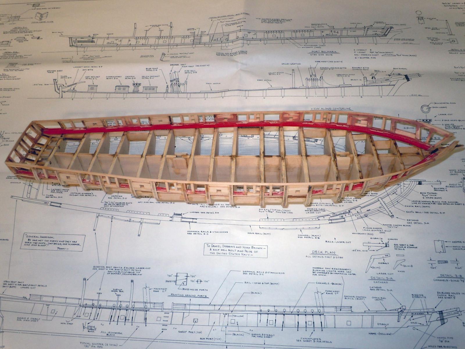
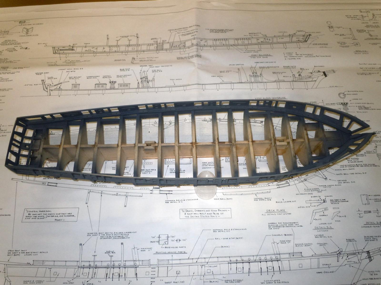
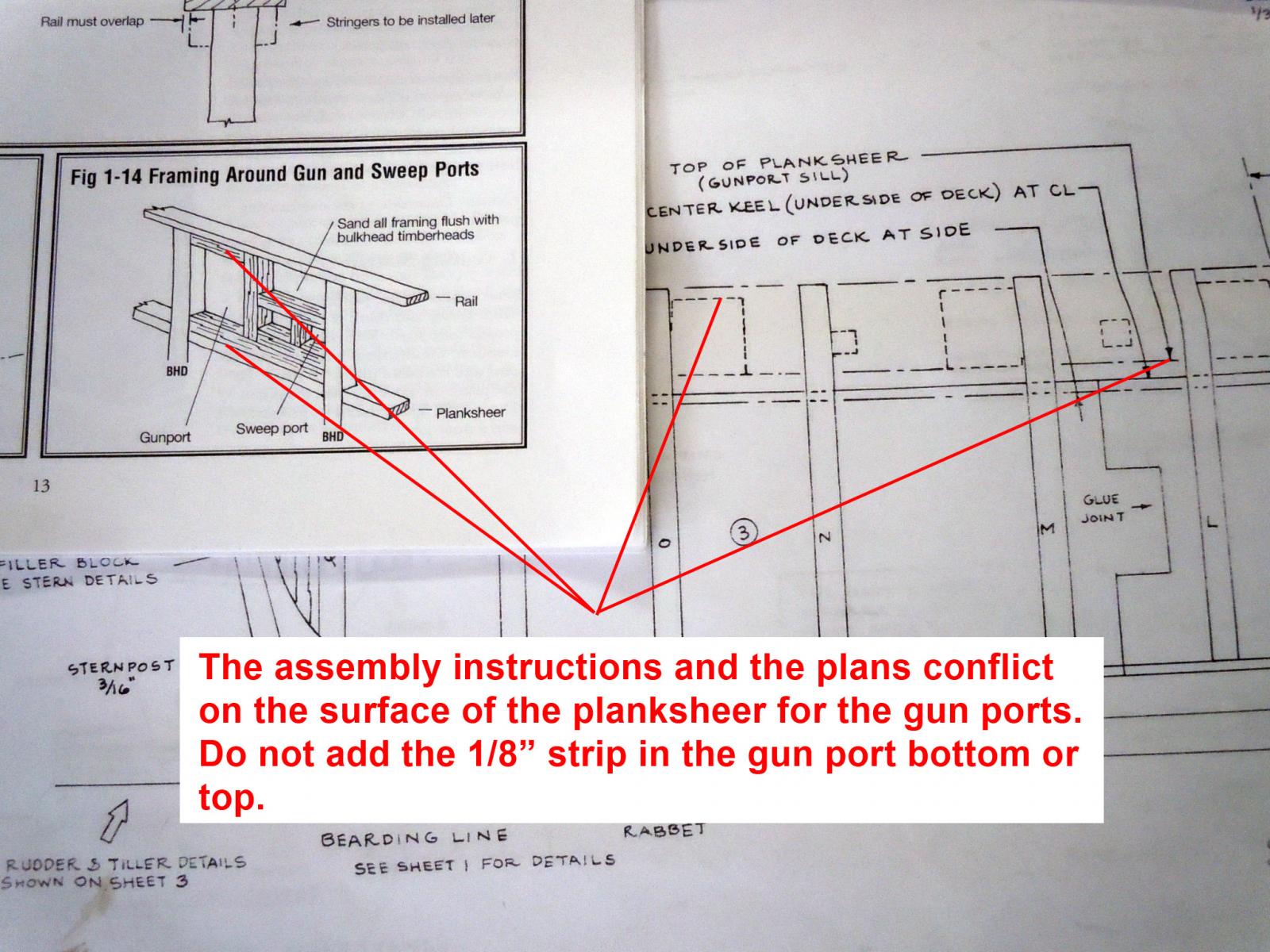
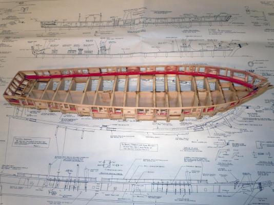
I finished up the fitting of the gunports and sweep ports and added gap filler as needed. I use automotive surface glaze putty which I have used for years and sands smooth with the wood. Once taken as far as I can see without the primer I then sprayed with gray primer and sanded again for easy identification of low spots glazed as needed and primed again. This shows finished before priming. And you can see areas where the red has been sanded away in fixes. Here are some pictures of the faired hull primed and ready for the next step. On the plans I see that there are 1/32" x 1/32" square strips on either side of the gun ports and sweep ports that the planking butts into to finish the end of the planking and are painted red. I have seen in other builds planking done over the gun ports without regard for these strips. QUESTION??? Should these strips be added first as I intended or ignore and plank over and retro fit? Any and all advice or experiences would be appreciated since my next step was to add them before painting the red again. Ken


- 440 replies
-
- 2
-
-
- niagara
- model shipways
- (and 1 more)
-
Yes I read your comments before I even posted mine above. Such are the adventures of model building. Ken
- 440 replies
-
- 1
-
-
- niagara
- model shipways
- (and 1 more)
-
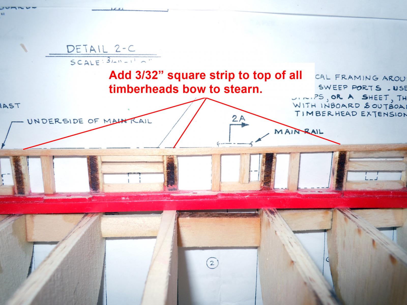
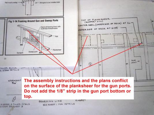
For future builders of this kit. I spent half a day fixing an error in the assembly instructions for this kit regarding the framing around the gun ports. See the pictures below that show best the problem and fixes. I am now thinking that a "Proof of Production" was not done for this kit. I also think that some of the build steps are out of sequence; for example when to add the top rail. The lesson I have learned is to now double check everything and read ahead and study both the assembly instructions and plans and sort out which is correct. Have a great day! Ken

- 440 replies
-
- 5
-
-
- niagara
- model shipways
- (and 1 more)
-
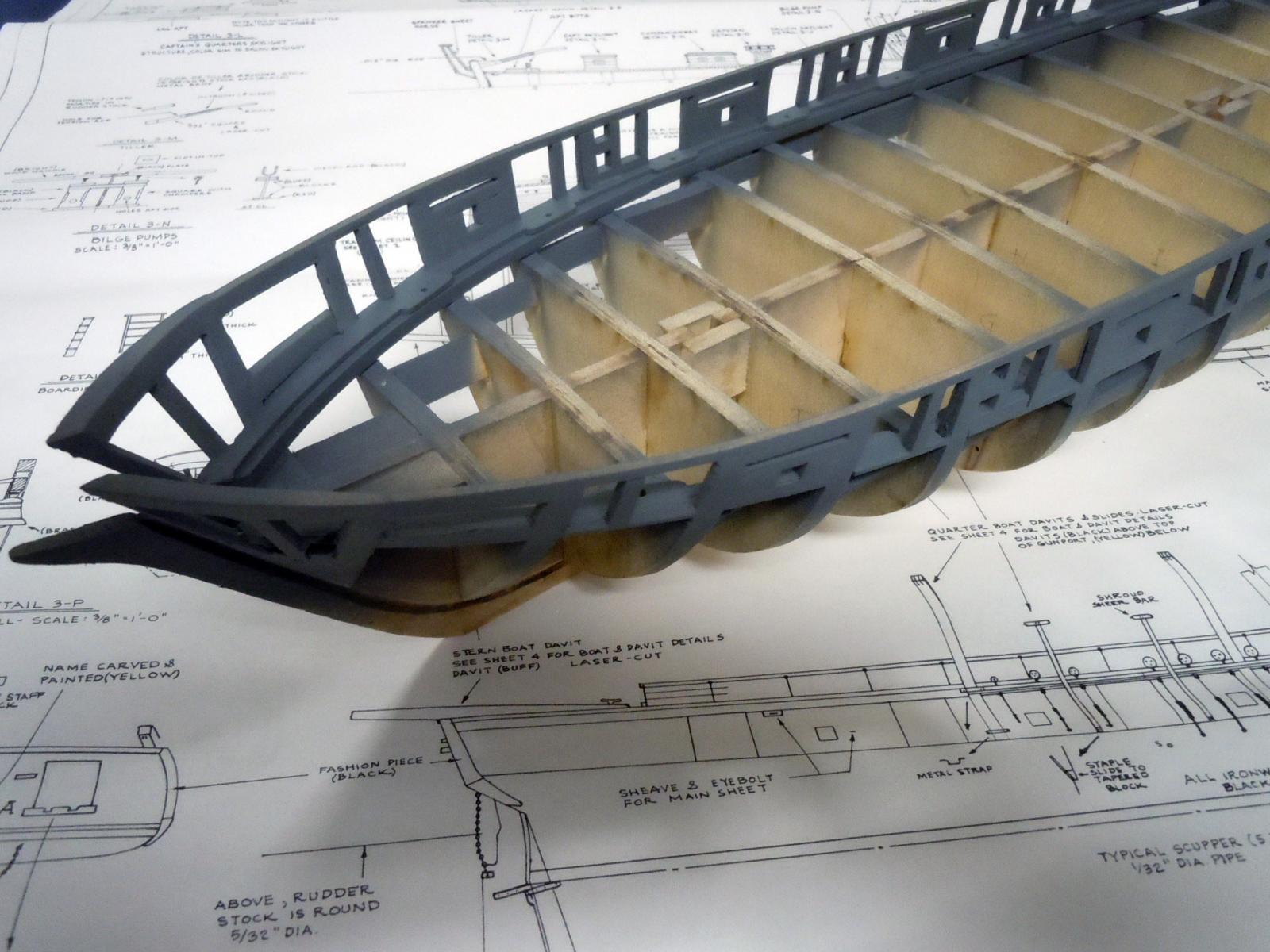
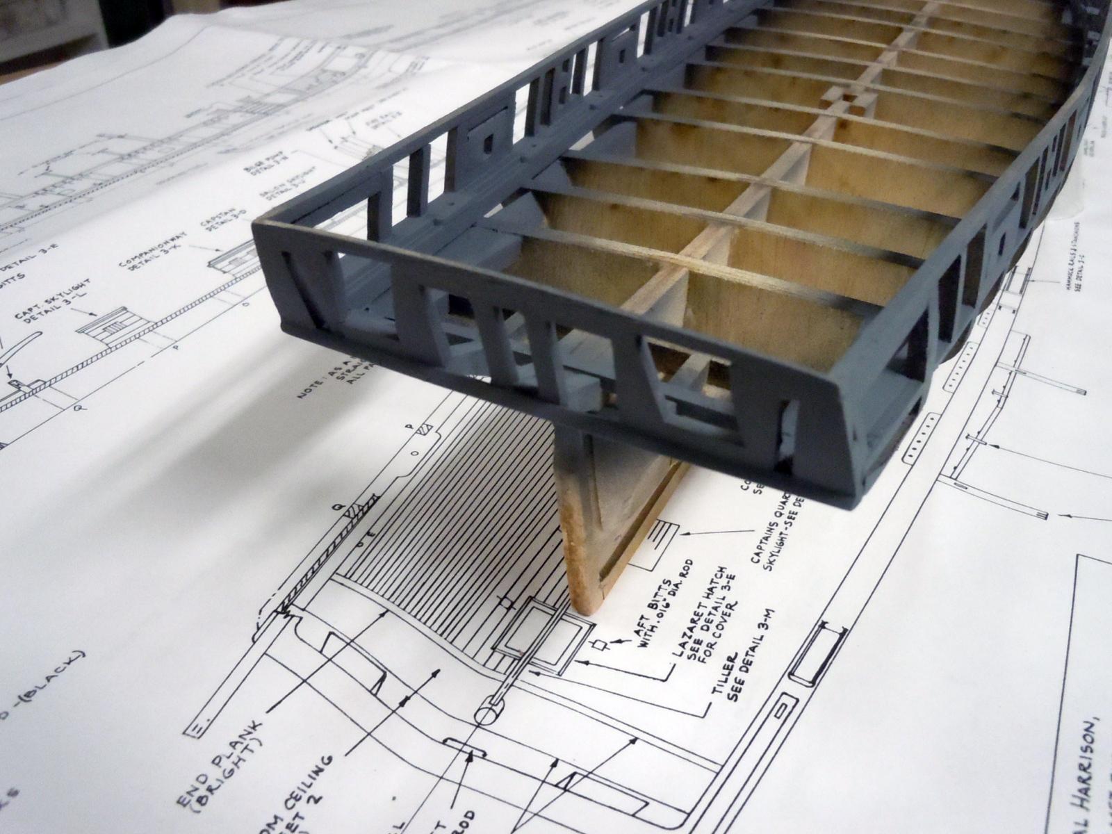
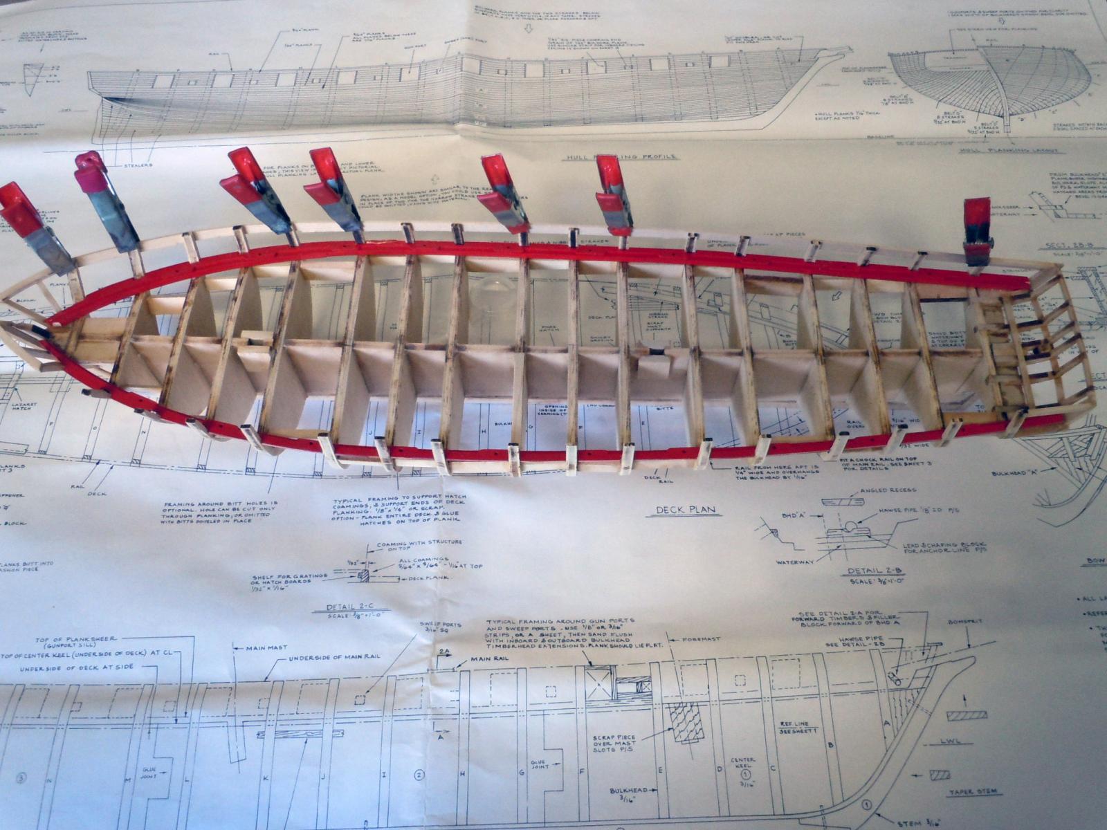
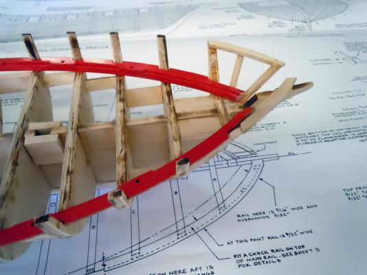
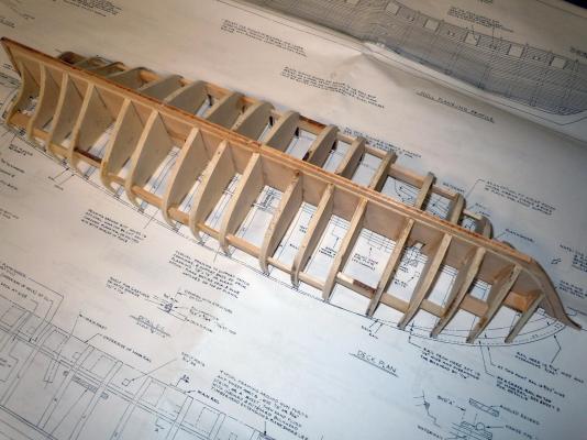
I added the bow and stern blocks and shaped them as needed. I then added the framework for the transom. Then per instructions I added the waterway and planksheer; but first I spray painted them red which I thought would be easier to do separate than in place. I then added the knightheads and forward timberheads. Notching for these in the filler block would have been easier without doing the planksheer first. However, the dremel made short work of it quickly. Will be reading ahead from now on to watch for these kind of issues. Here in the picture below I am truing up the bulkheads. I clamped a thin piece of scrap to identify the ones out of alignment. I then very carefully cracked the offending bulkheads and added CA to glue in proper place. With plywood this is done very easily. They will be then sanded accordingly. The picture below shows a closeup of the bow section the waterway and planksheer end where the bowsprit will lay. I also have trued up some of the bulkhead deck surface planes that are not true either. I will continue to cleanup before adding the top rail and gun framing. Ken

- 440 replies
-
- 4
-
-
- niagara
- model shipways
- (and 1 more)
-
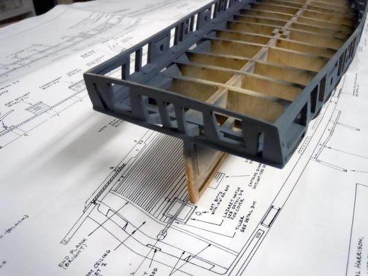
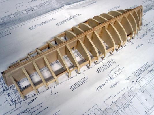
The Fair-a-frame worked like a charm and I was able to make quick work of adding the bulkheads. I then used scrap basswood as bridging between the bulkheads to reinforce the outer edges for sanding. Once the glue set I then sanded the bulkheads to develop the shape of the hull and still have a little fine tuning to do yet. Here are a couple of pictures of where I am at so far. Ken
- 440 replies
-
- 4
-
-
- niagara
- model shipways
- (and 1 more)
-
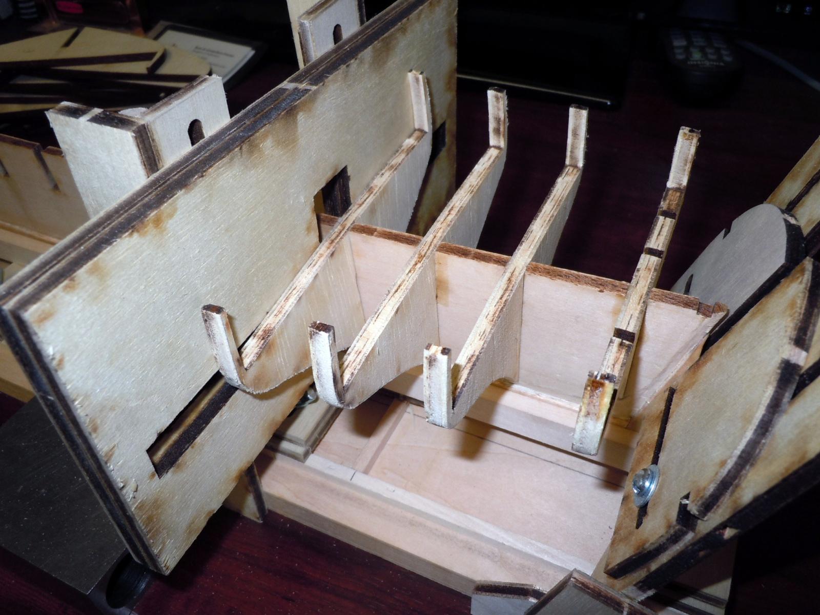
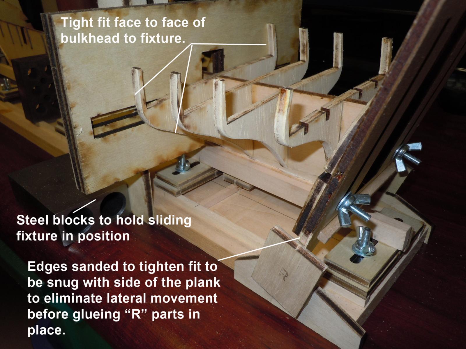
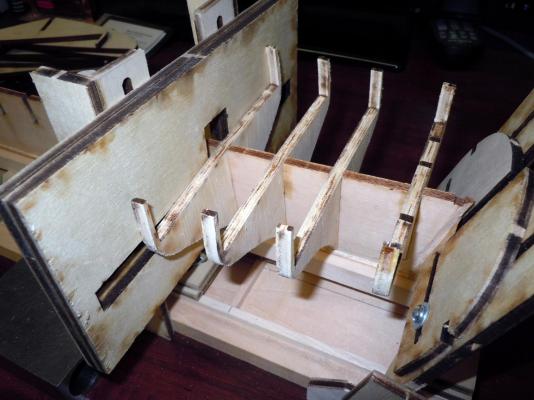
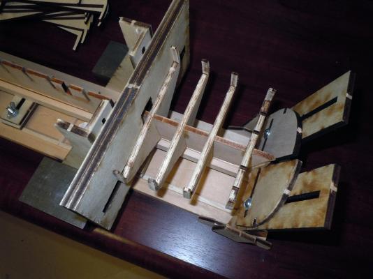
Yesterday I spent some time and assembled the Fair-a-frame to add the bulkheads. I am glad I am an old scratch builder from way back. The instructions came with two pages of corrections and the instructions were a little confusing since the drawings and some of the parts did not match. I also was advised that this was not needed to assemble; however I ordered it since I have three kits that will be built over time, being a kit designer for Model Expo I am always looking for what works and what does not and why. Once assembled I then understood what the intent of the fixture was; there were no instructions on how to use it but that was quickly sorted out. One needs to keep in mind that time must be spent setting up the front and rear holders to keep the center section vertical and square to the plank and be screwed in place at each end. I also used a large spring clamp that was advanced as each bulkhead was added. Having the clamp really helped when sanding the slots for that perfect fit. The photos above show how it is used as this bulkhead is glued in place. The main fault in my humble opinion was that the front and rear vertical fixtures when following the instructions were too loose. I sanded the four edges for a snug fit then glued the "R" pieces in place. See the picture below. Once these fit tight and the moving center part aligned correctly and aided with steel blocks and spring clamp the Fair-a-frame works as intended. I being a belt and suspender kind of guy also checked each one with a steel block for squareness and so far they are true. Now onto adding the rest of the bulkheads. By the way I started at the rear and am moving forward; one can also start at the front and move to the rear. This is just a personal preference. Ken

- 440 replies
-
- 5
-
-
- niagara
- model shipways
- (and 1 more)
-
Laxet, It looks like I will benefit by following in your footsteps. This is my first ship build as well and trying to learn about ship building. I will for sure be checking out you build and progress as I build the hull. Right now I am cutting in the gaps at the keel for the planks. Have a great day! Ken
- 440 replies
-
- 1
-
-
- niagara
- model shipways
- (and 1 more)
-
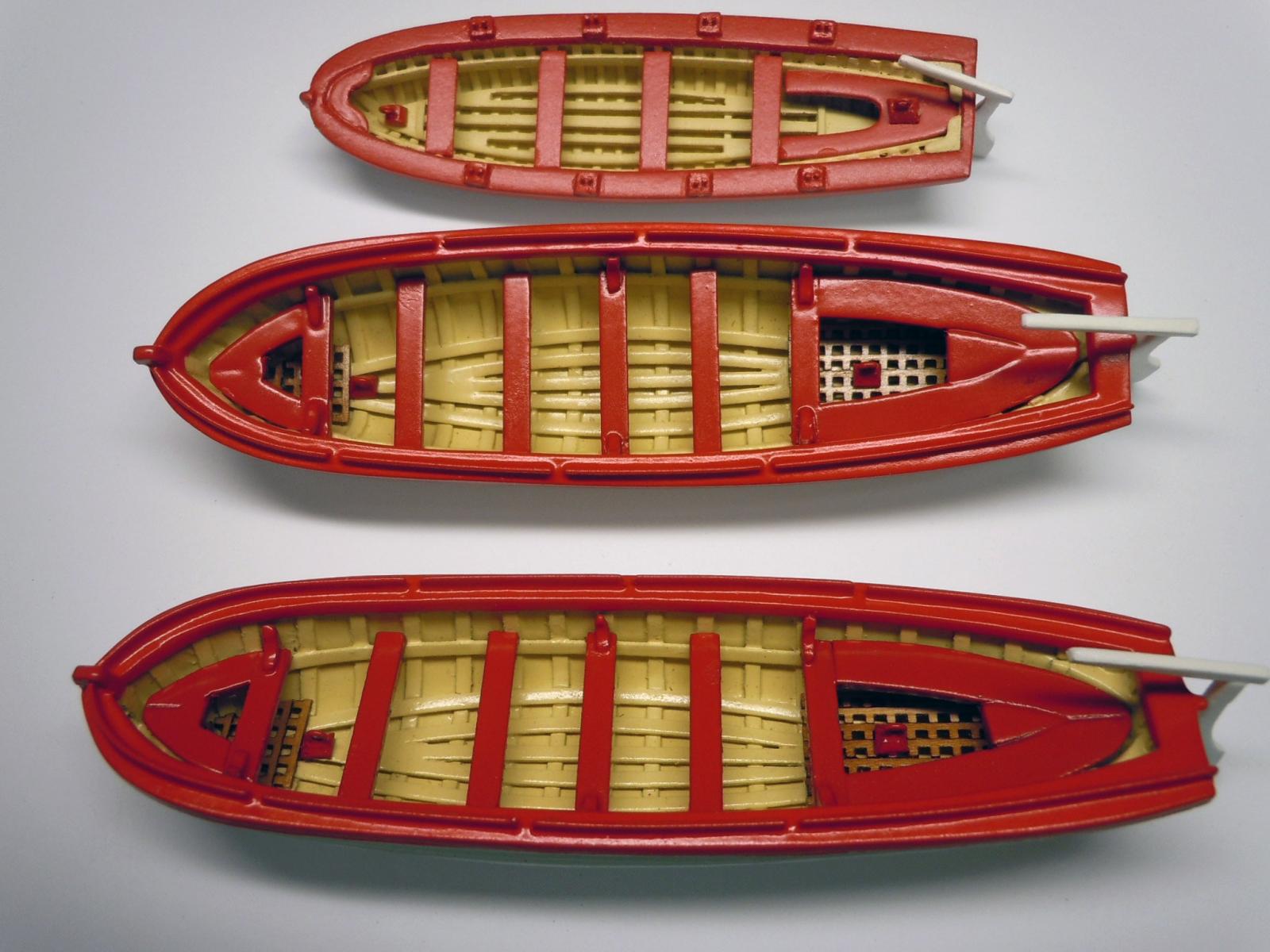
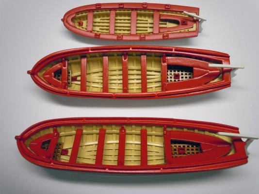
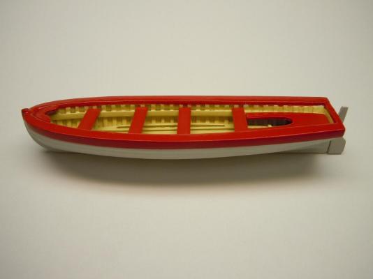
Here is a picture of the yawl and two cutters competed and ready to go. I may add the hinge straps on the tillers down the road when I can find a picture of what they looked like. These were fun to build and I learned a bit about boat building and some new nautical terms. Now onto the big boat. Ken
- 440 replies
-
- 7
-
-
- niagara
- model shipways
- (and 1 more)
-
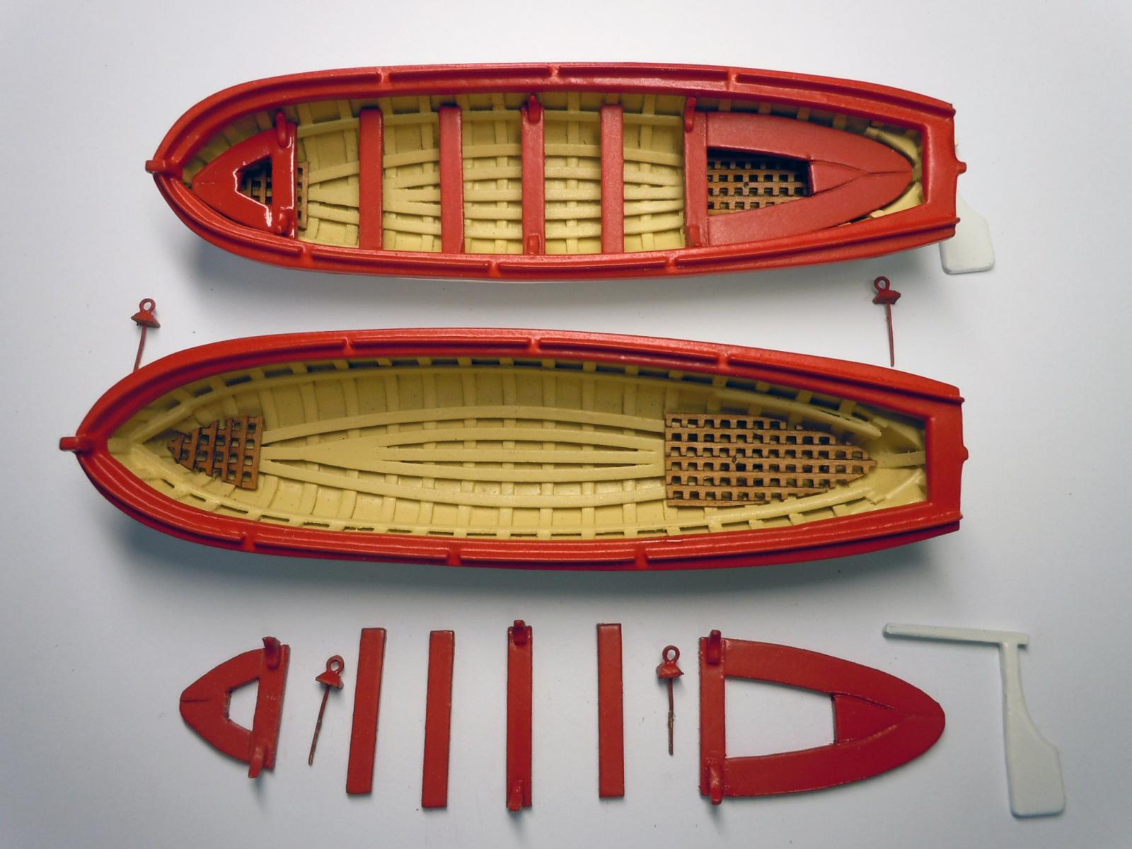
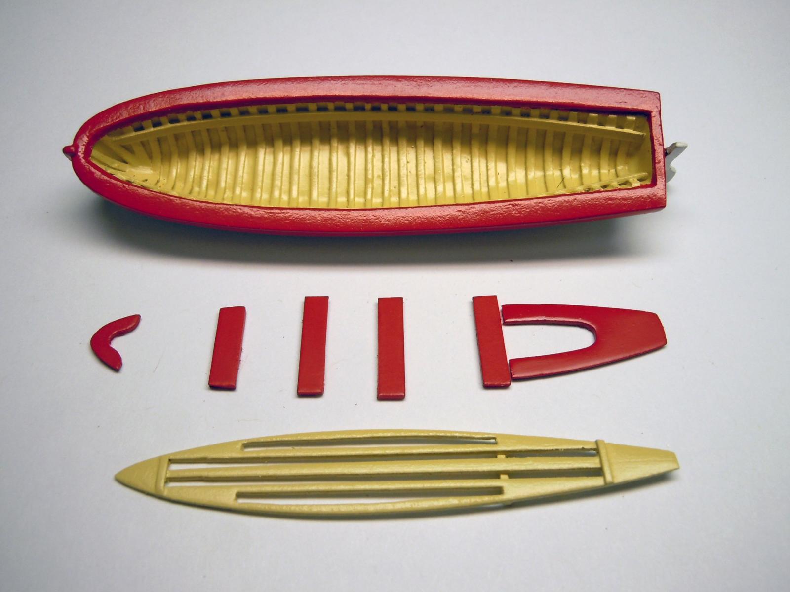
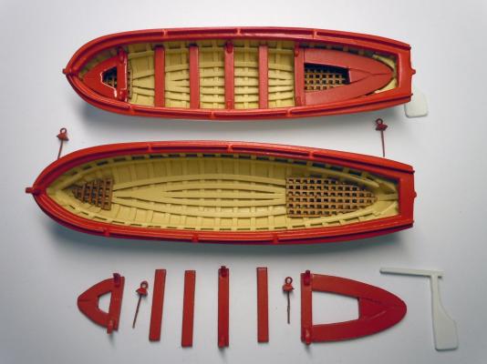
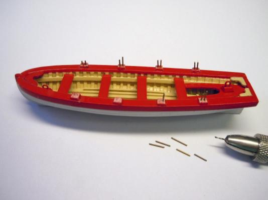
After sorting out the color "Bright" I finished up both the rear and front grates; then I made the lifting hooks. I sprayed the interior with Satin Clear and with spray the parts as well prior to final assembly. Here is a picture of the two cutter sets of parts. Now just to assemble them all. Next to start the "big" boat. The keel assembly has set for the 24 hours as suggested in the instructions. Ken
- 440 replies
-
- 8
-
-
- niagara
- model shipways
- (and 1 more)
-
Bill, Thanks! I saw the color notes after I posted; I focused more on the drawings than the text. Thanks again! Ken
- 440 replies
-
- 1
-
-
- niagara
- model shipways
- (and 1 more)
-
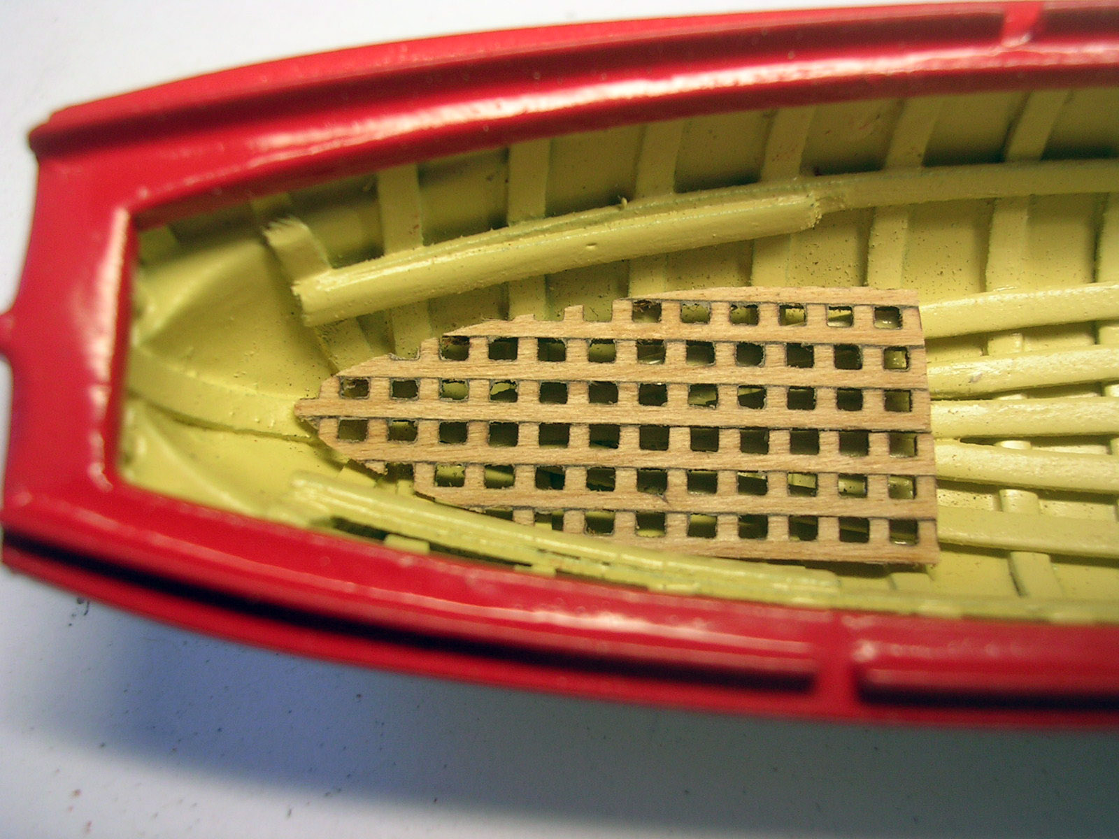
Finishing up the cutters while waiting for the keel and center section glue to set. Have a quick question on the grating for both the cutters and the ship; what color should they be? There is only one reference on the plans on the ship with an arrow pointing to the grating with the term "Bright". Thanks for the help in advance! Ken

- 440 replies
-
- 7
-
-
- niagara
- model shipways
- (and 1 more)
-
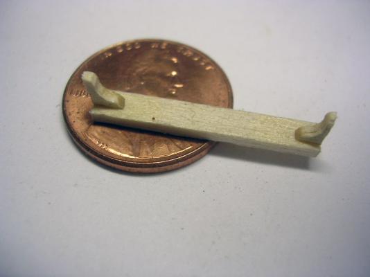
Before getting to the rowlocks I decided to do the bow sheet and stern sheet and floor boards. I did the floor boards as separate parts to better paint the interior. Here I started the rowlocks by forming wet pieces of the 8003 stock and set them aside to dry thoroughly before trimming the ends and filing in the locations. While waiting I cut the thwarts and glued the end ones to the sheets. I then cut the knees located on the thwarts. Here is a closeup of the knees to show the scale. Six needed for each cutter. The knees in position and glued to the thwarts for painting. Once all the parts were fitted I then painted the interior of the cutters and will allow to dry while I sort out the building of the grates which are located at each end. The row locks and rail will be painted red.


- 440 replies
-
- 5
-
-
- niagara
- model shipways
- (and 1 more)
-
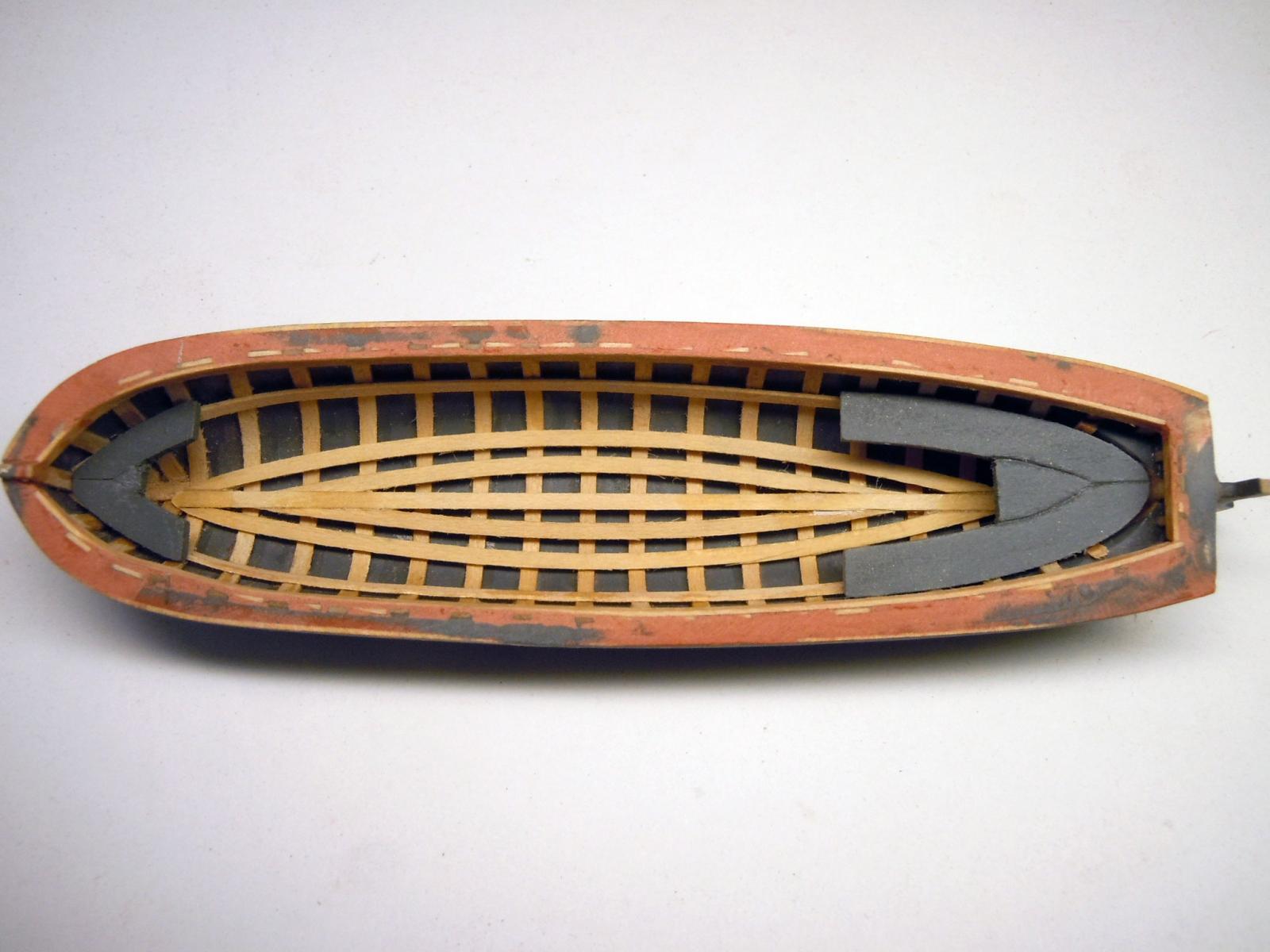
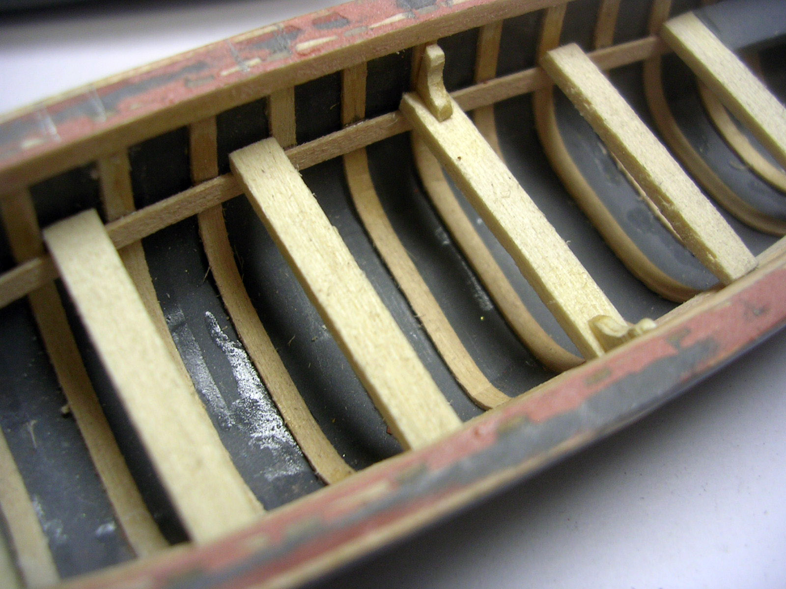
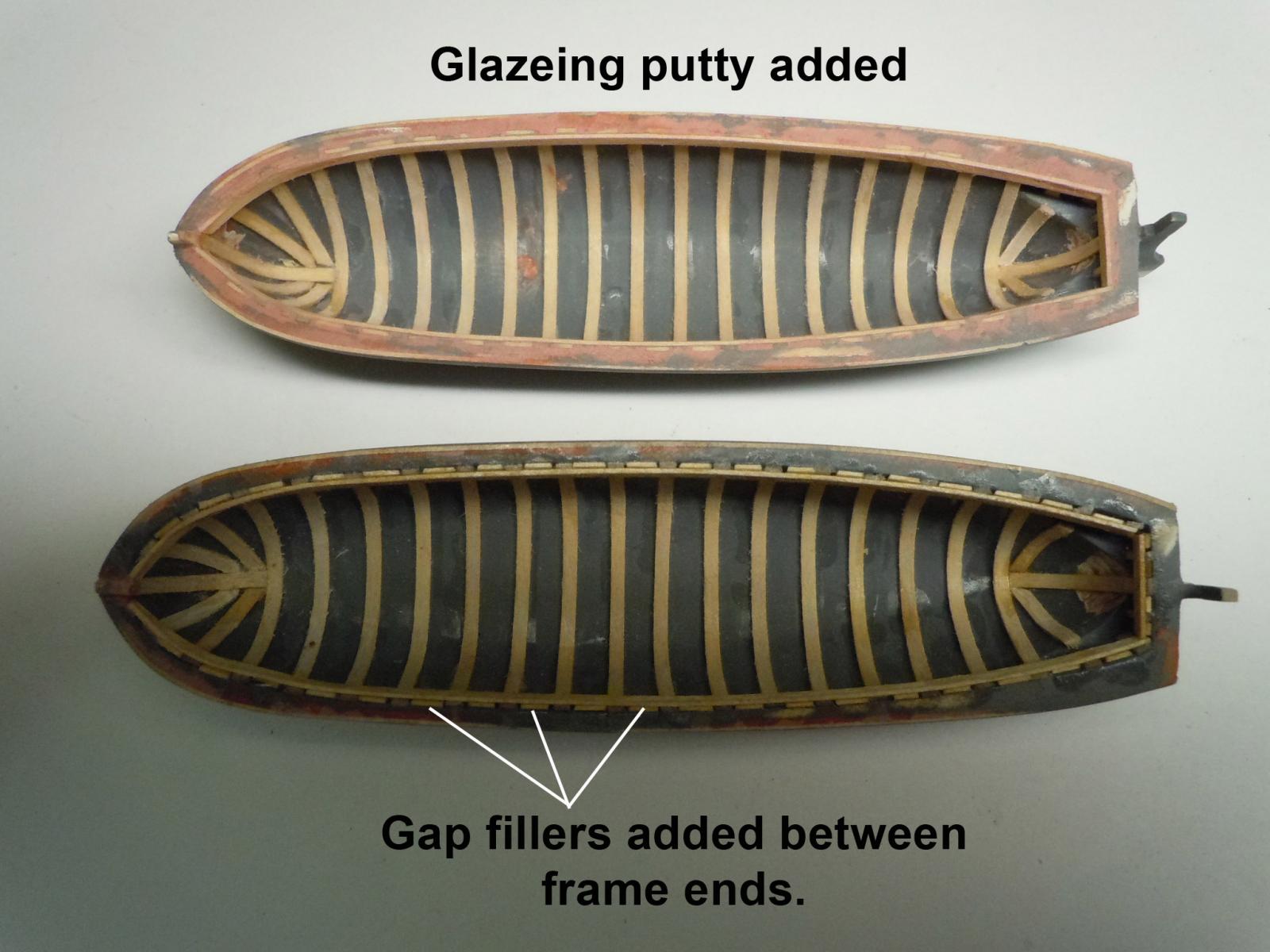
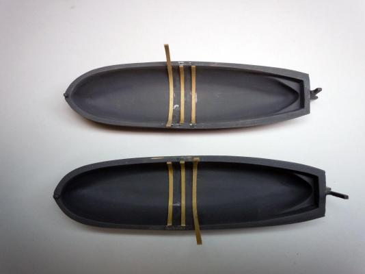
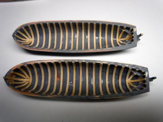
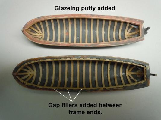
I have moved to the interior and cored out the bottom layer and blended it to it's final shape after a few sanding and filling operations. The smoother and cleaner the inside the better the results for the framing. Here is the start of the framing, I made a spacing tool to help the frame locations. Here are the two completed framing operations. Now I added the inner member to the top of the frames. The bottom picture shows the inner members in place and the gap fillers in between the top of the frames to form the rail top. The top picture show the finished rail surface filled in with glazing putty and sanded. Next I will add the rowlocks to the top surface of the rails once they are primed and final sanded.
- 440 replies
-
- 7
-
-
- niagara
- model shipways
- (and 1 more)
-
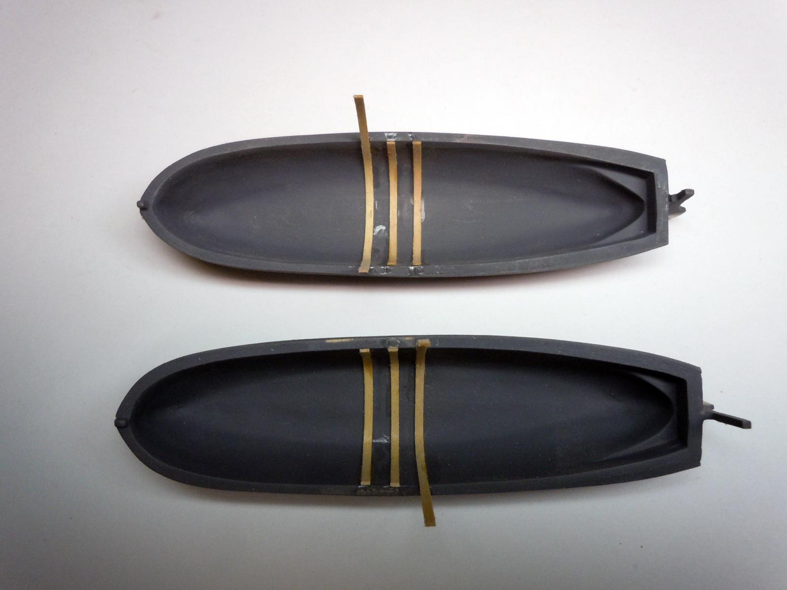
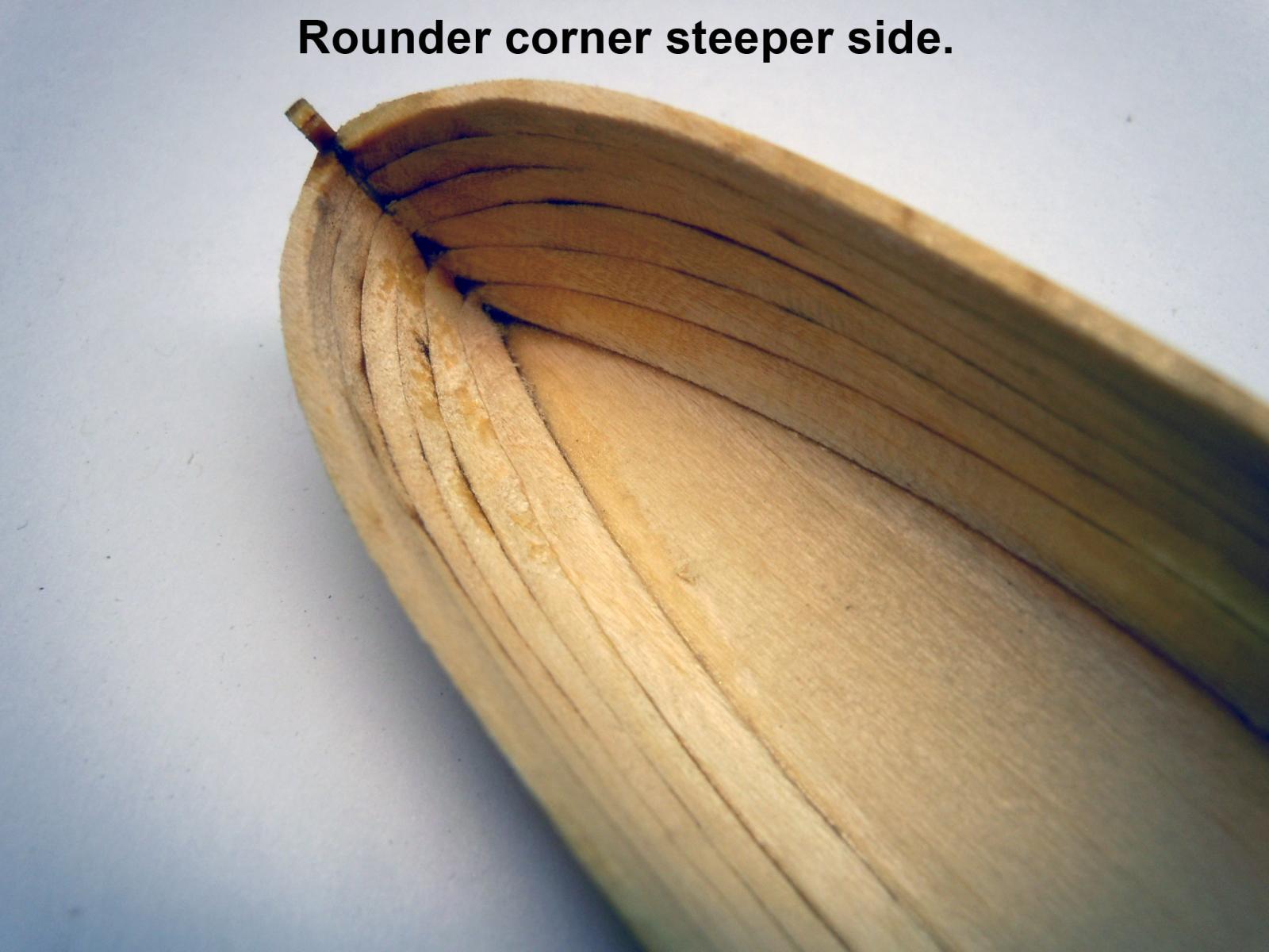
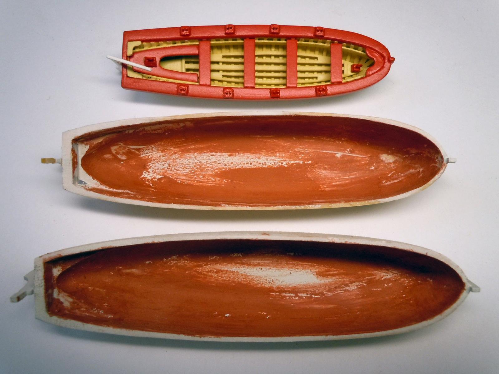
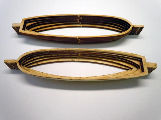
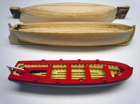
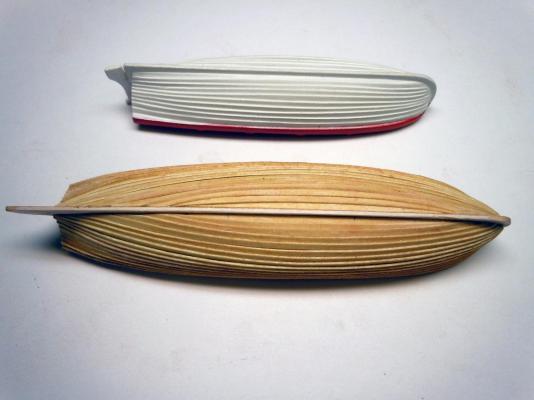
Here are the layered laser cut parts to form the cutters. I followed the instructions and glued the layers by aligning the end tabs which later turned out to be a mistake. A couple of tips for those who may build this kit; before removing the parts from the carrier sheet draw an line across the top on each part so you will know which side of the part is up. Laser cutting causes a slight angle on the edges of the parts and the thicker the stock the greater the angle; this will help when gluing together and reduce filling issues. It turns out the left to right profiles are not exactly symmetrical so the line will help in stacking, when gluing together rather than gang the parts in one stack glue them one at a time centering the profiles on each other respecting the front to rear alignment. I also left the bottom of for easier handling and once close to the bottom of sanding away the interior then add the bottom. This shows the profile differences. Here is the outsides rough sanded prior to priming. Also the yawl is in the background for size reference. Here are various stages of filling the undercut that result from the misalignment of the tabs. I like to use an automotive glazing spot putty due to it's ease of working with and quick drying and sanding. The best applicator based on size of the cutter and being on the inside turned out to be my index finger. Lacquer thinner easily removes it. Now I started the planking again using the Midwest #8003 strips. Soaked in water and easily but carefully edge formed for the desired curve as seen in the picture. The first several are tack glued on center of each overlap and the ends placed against the keel for trimming and then fully glued in place; once halfway up I then started at the rudder end and carefully overlapped and glued. Here is the end result of the first cutter's planking; now onto the next one and the final finish filling and sanding of the interior now that it is much stiffer with the planking.


- 440 replies
-
- 8
-
-
- niagara
- model shipways
- (and 1 more)
-
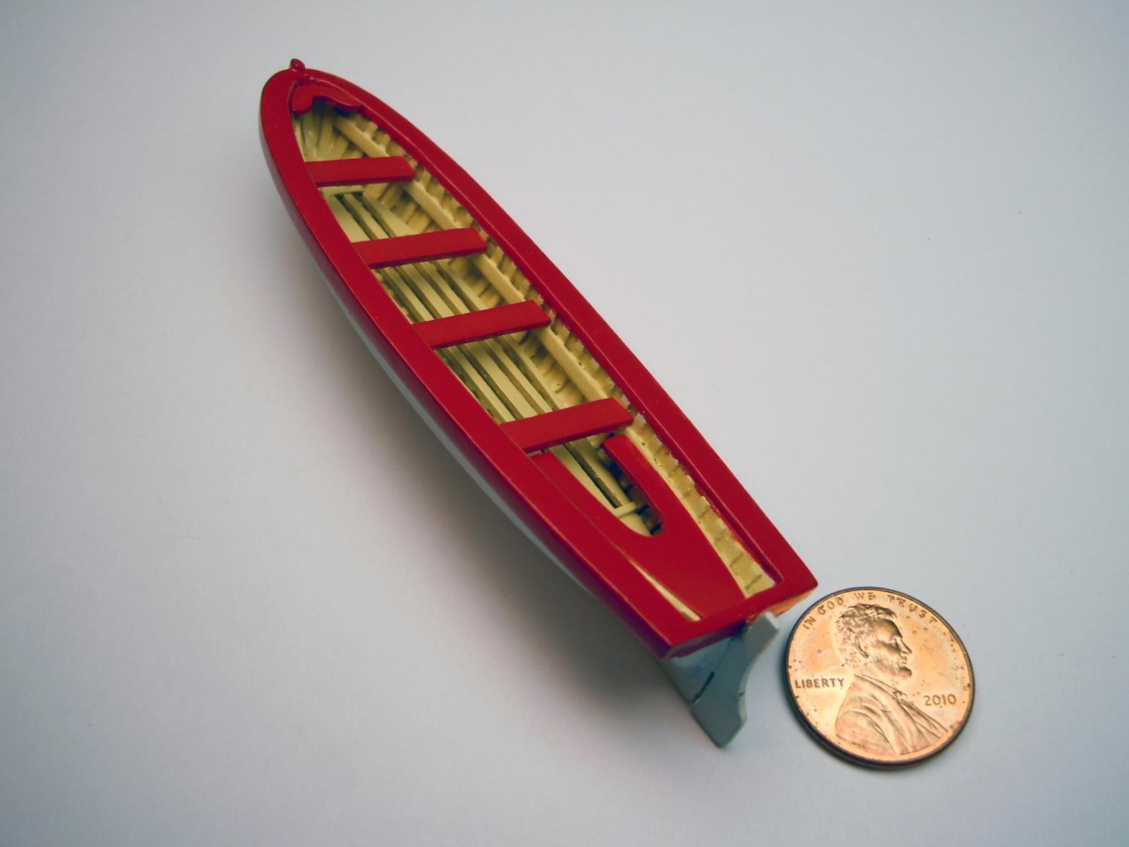
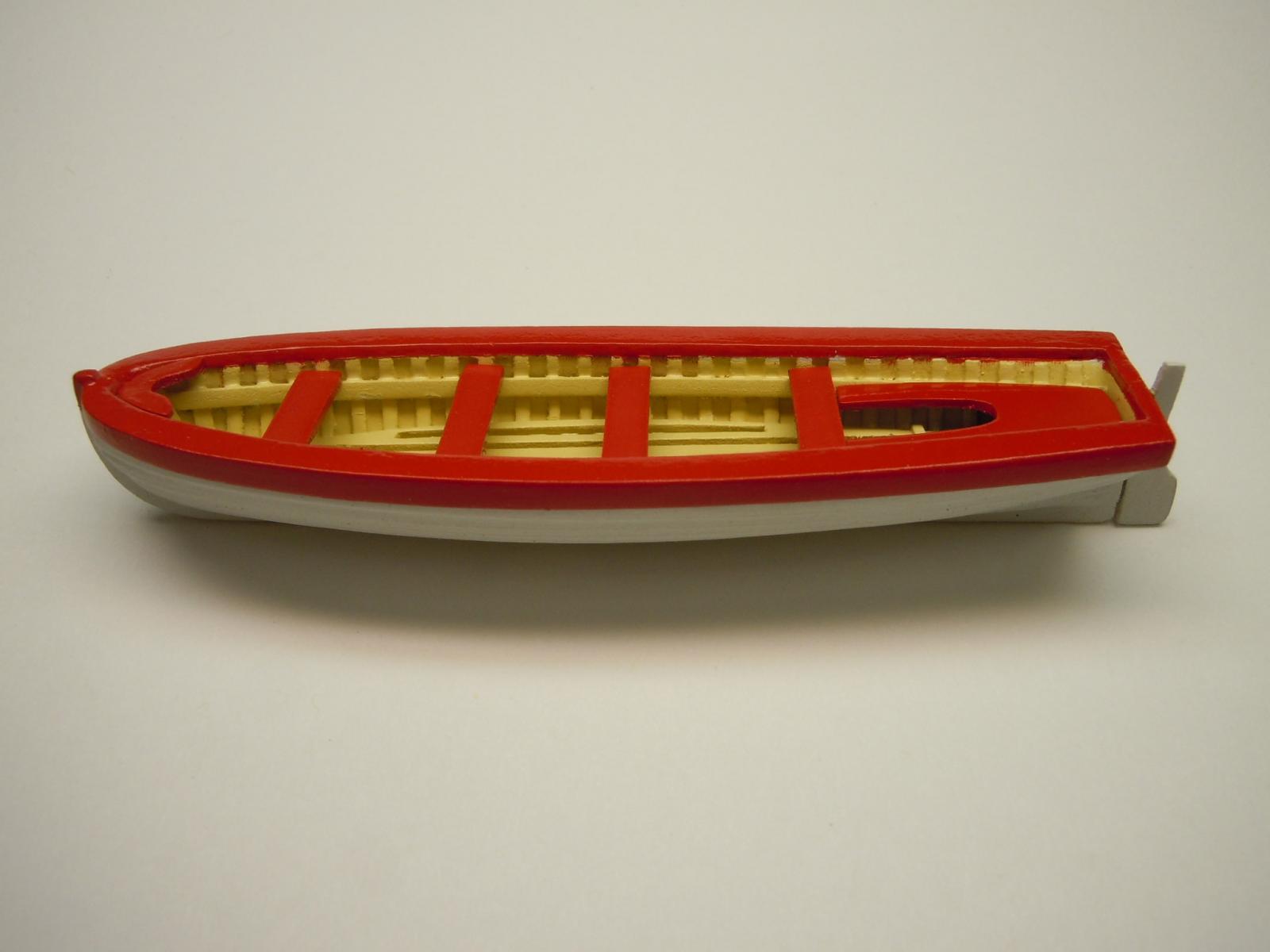
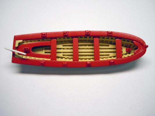
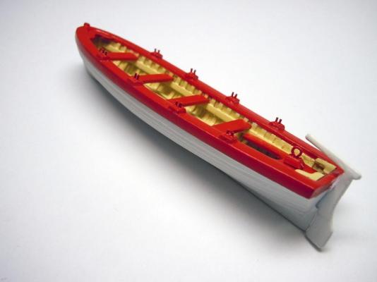
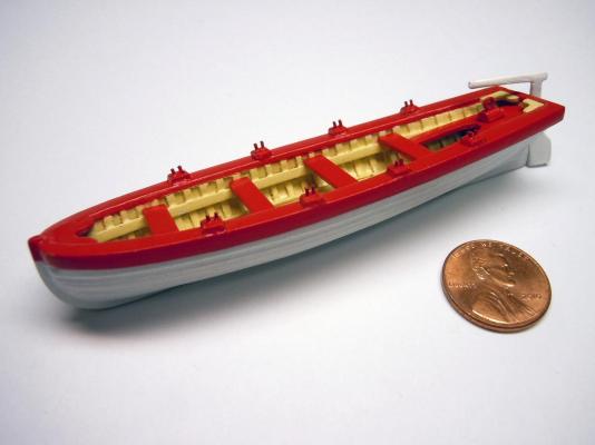
Here I have added the lifting rings, the rear knees, the breasthook and started the thole pins using .020" brass rod inserted into drilled holes. Once the CA is set they were cut to length and then filed for flat tops. The tiller was removed during the build and will be added at a slight angle to not interfere with the lifting ropes. Here is the finished top view showing the interior. Here is the finished left rear. Here is a left front view with a penny for scale reference. Next, I will start the two cutters that will benefit from the lessons I have learned building this yawl.
- 440 replies
-
- 10
-
-
- niagara
- model shipways
- (and 1 more)
-
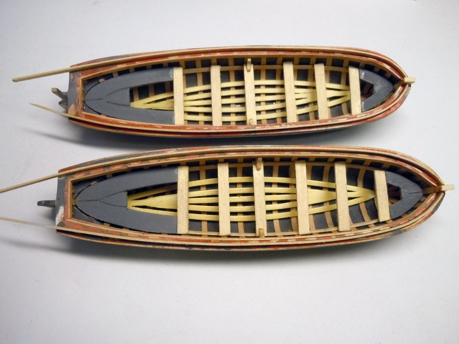
Here the ribs and top rails and have been added. Next I cut and fitted the floor boards, thwarts, breasthook, and stern sheet. Then primed and painted them. Here is a view with a penny for scale reference. Here is a side view. Next I will add the rear knees, lifting rings, tiller handle and thole pins. Does anyone have an image of what the thole pins really look like on a boat. I am familiar with oar locks are these an earlier version? I have learned a great deal building this yawl that I can use to build the quarter boats.


- 440 replies
-
- 9
-
-
- niagara
- model shipways
- (and 1 more)
-
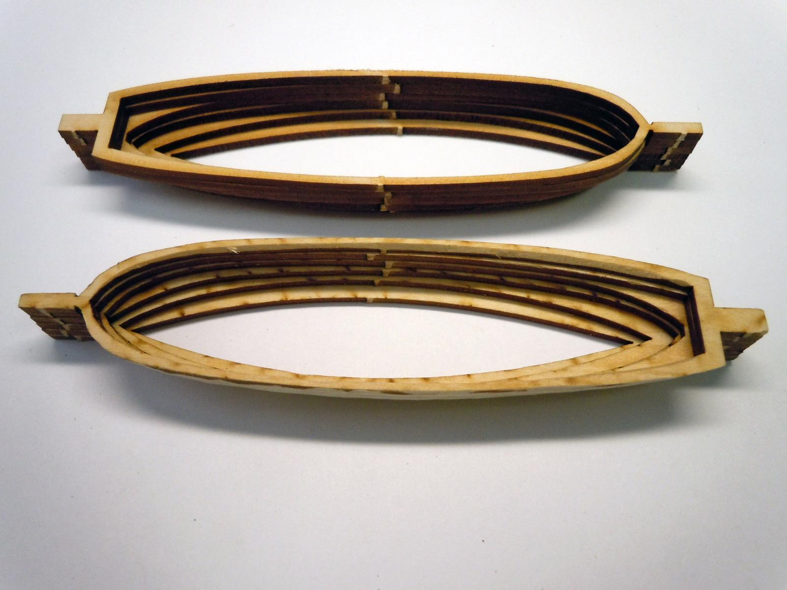
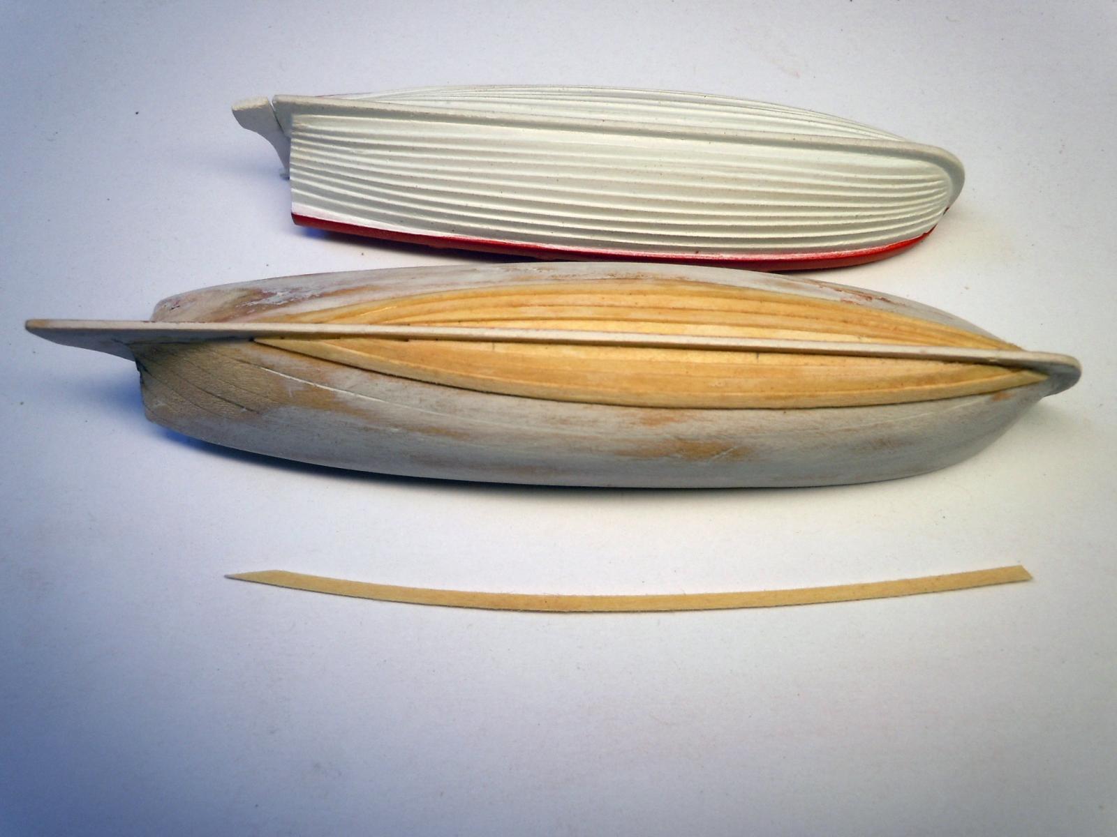
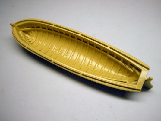
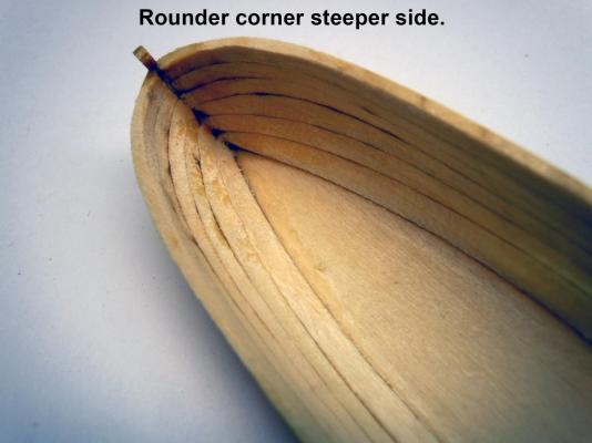
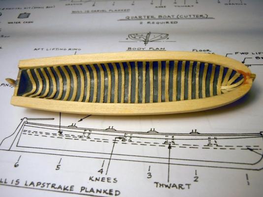
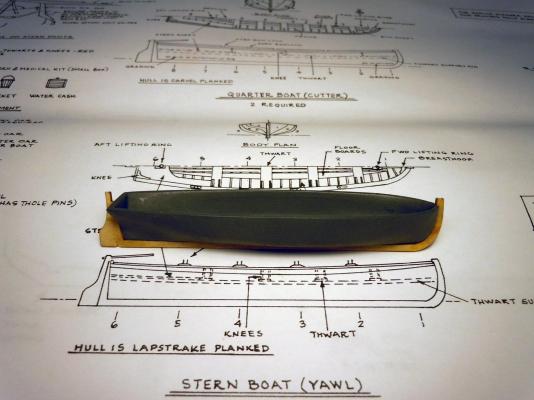
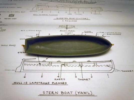
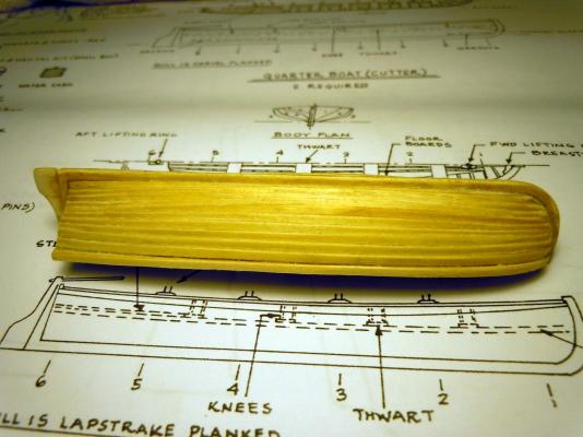
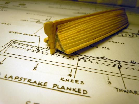
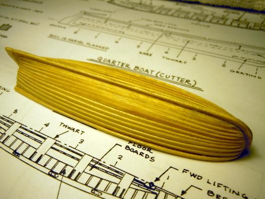
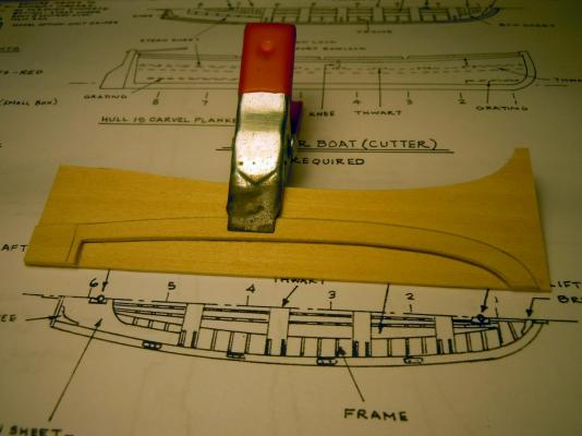
Starting over with correct title. I started the yawl first to learn the basis of ship building. I layered the parts and carved the basic shape per instructions and then primed and sanded to develop the final surface. Here is a view of the inside. It got very thin in places and I also noticed while carving the end tabs and center line did not exactly line up. I then looked at adding the side layers; from my airplane building stock I found that Midwest item #8003 .0208" x .0625 scale lumber was what I needed to use; soaked in water and started at the bottom keel and worked my way up doing both sides at the same time to match. Please bear with me since this is my first attempt at ship lapping. Here is a rear view. Here is an overall view with rub boards added. This shows tracing the top board to match left and right and were then carefully trimmed to to the inside ribs. Next I will start adding the inside details. Also need to learn how to add the text below the pictures.
- 440 replies
-
- 4
-
-
- niagara
- model shipways
- (and 1 more)