HOLIDAY DONATION DRIVE - SUPPORT MSW - DO YOUR PART TO KEEP THIS GREAT FORUM GOING! (89 donations so far out of 49,000 members - C'mon guys!)
×


xken
-
Posts
841 -
Joined
-
Last visited
Content Type
Profiles
Forums
Gallery
Events
Everything posted by xken
-
 David, mostly just Krylon rattle cans. Over the years I have had good luck with Krylon even though I had a couple of airbrushes it is more convenient to just step outside the studio and give these parts a squirt; especially with a basic color palette to work with. The hardest color to come up with and it is not available locally was the Buff and I found a Tamiya Light Sand (TS-46) which I am happy with. Ken
- 440 replies
-
- 1
-

-
- niagara
- model shipways
- (and 1 more)
-
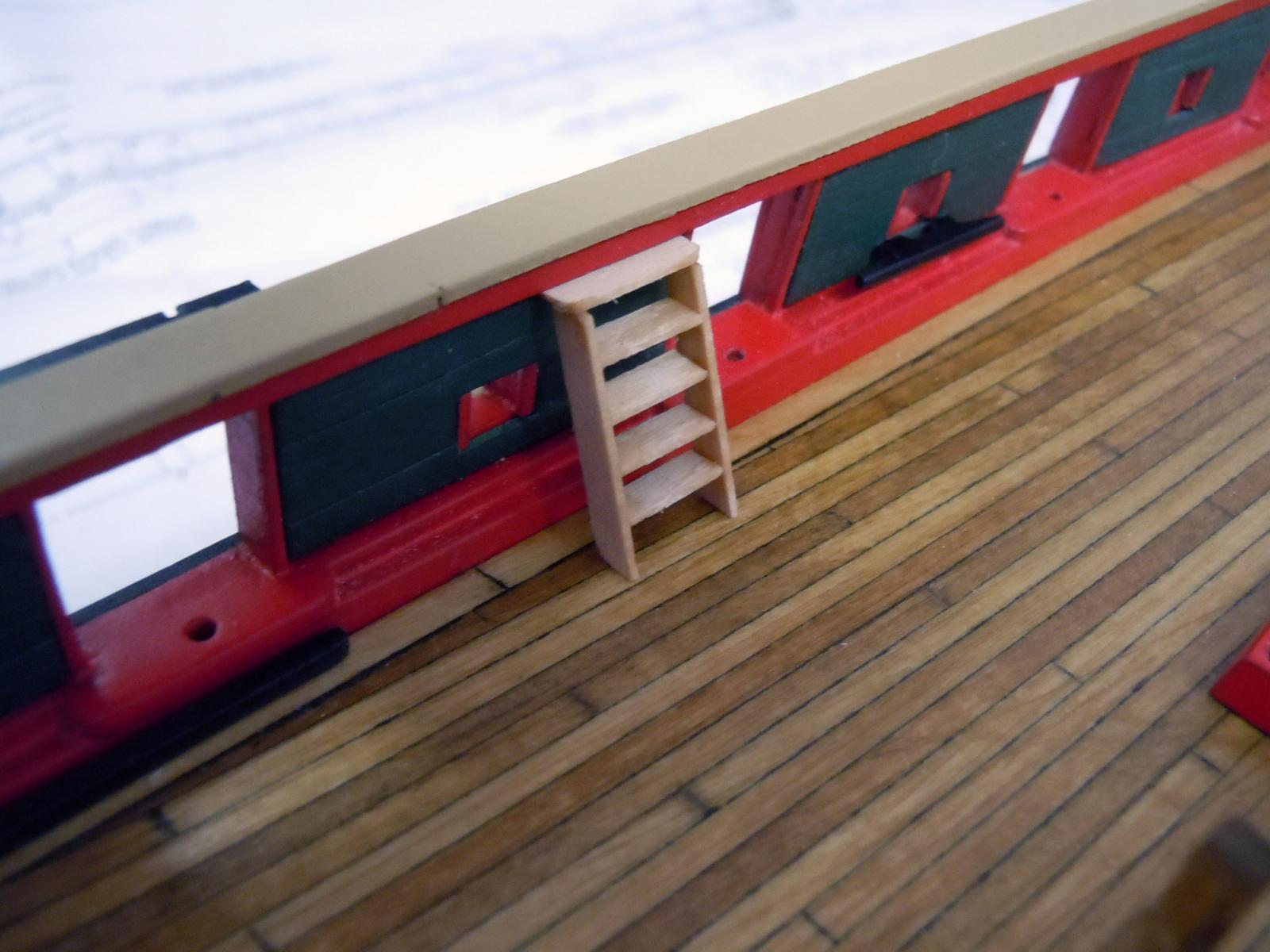
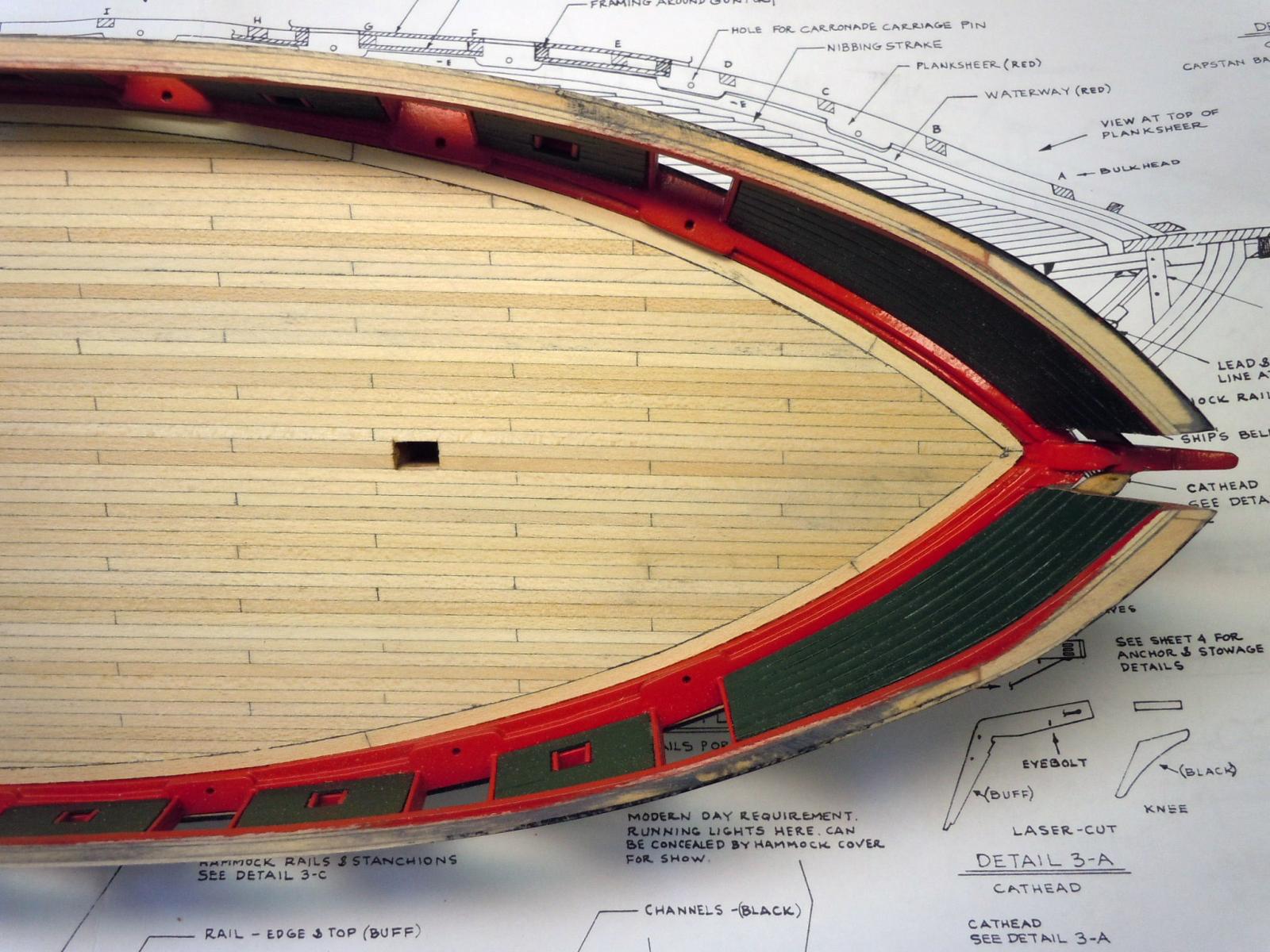
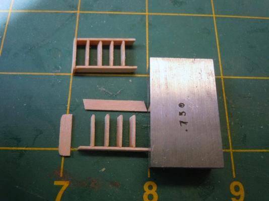
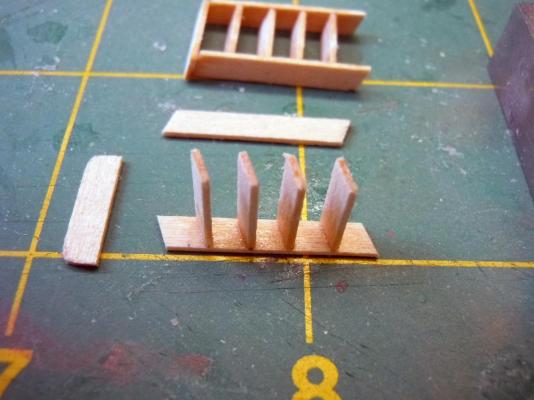
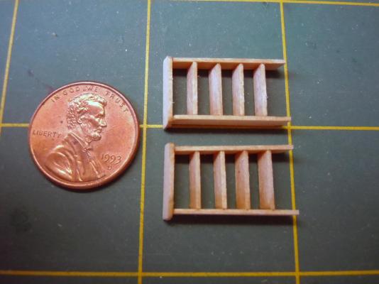
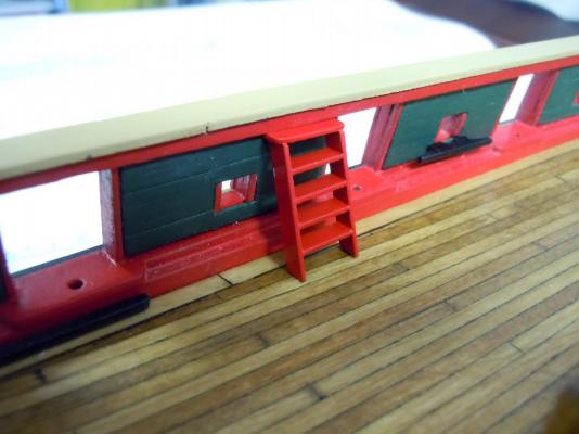
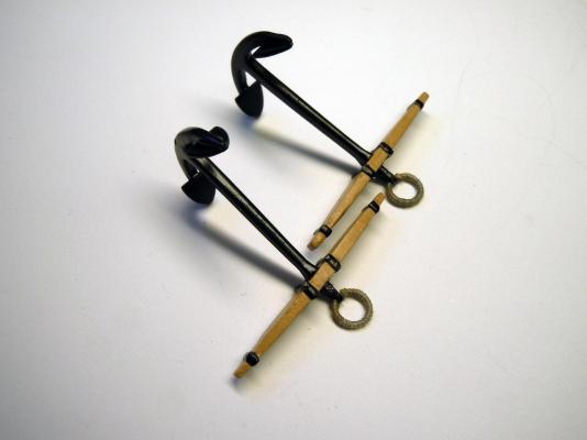
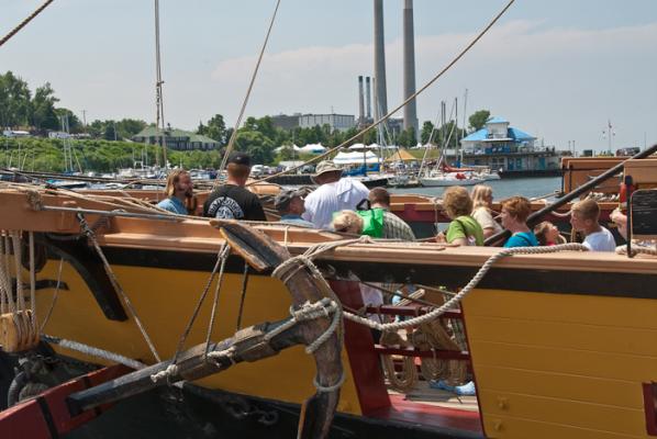
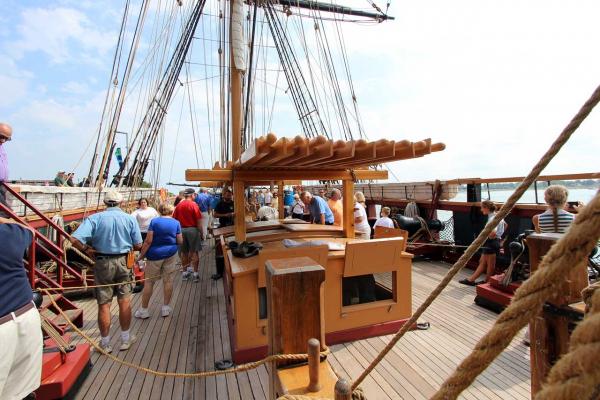
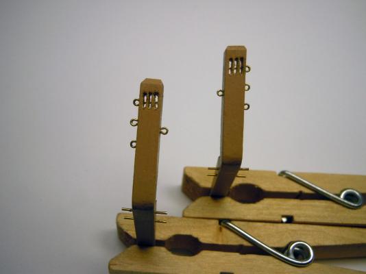
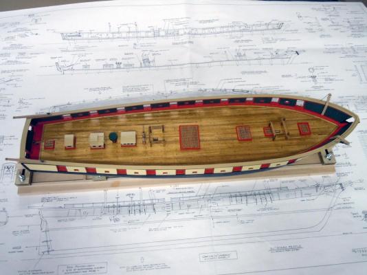
I finished the forward channels and moved on to the two boarding ladders. Again another surprise with the plan sheet details for the ladder and the assembly instructions not matching. I checked internet images for the direction to follow. The assembly instructions suggested building an assembly fixture which after reviewing I decided that I could make them faster off hand. First I cut all the sides and then the steps. I drew the spaced ladder steps on two of the sides at the required angle for reference when adding each step. I laid the side with the foot against a small steel block and both aligned 90 degrees on the building mat grid. I then carefully glued each step using the pencil lines for reference with CA and checking them for 90 degrees to the side. Here are the two with all the steps glued in place. Here is a test fit in location on the deck indexing below the main rail and angled foot resting on the deck. Once checked in place they were painted red. In checking pictures of the actual replica ship I noticed a third ladder on the rear port side to access the rear yawl. This ladder is not shown on the plans; my question is should it be added? Or was it common practice to have ladders to access the rear yawl for this class of ship? I also built up the anchors and even wrapped the jump ring with thread per the plans. The plans call for the wood portion to be bright. Here are my anchors. In the same section of reference photos of the replica I also saw a picture showing the wood portion painted. See attached. Again, what was the correct way to finish these parts? I am new to ship building and in previous scratch builds I always used real subjects for reference on details. Here is the picture of the replica ship anchor and I am sure that they probably did it correctly. Comments welcome on this one. Also here is a picture showing the 24 foot long oars in storage rack. This detail is not even shown anywhere on the plans or assembly instructions. They only show the yawl oars stowed on the rear port side wall. Am I just being too picky on details; but a storage rack for 24' oars is a big detail to be overlooked or not even mentioned. Comments welcome on this one as well. Now to sort out where to start next. Ken

- 440 replies
-
- 6
-
-
- niagara
- model shipways
- (and 1 more)
-
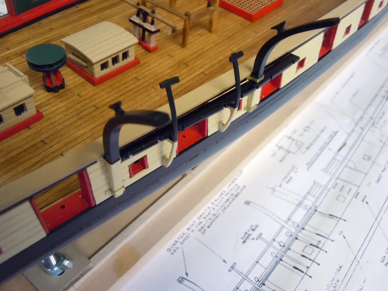
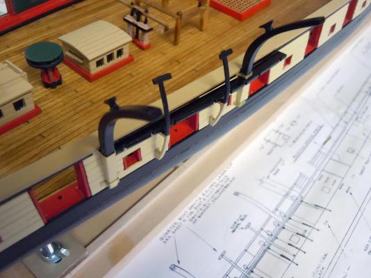
I moved on to the quarter boat davits and slides which required some fussy work forming the brass straps that hold them in place as well as making the slots in the ends of the davits to make them work. The slides were soaked in water and formed wet then held in a fixture to dry curved. The brass brackets were hand formed to each location since the top and bottom were two different depths. I then realized that the channels had to be made first and glued in place before adding the slides. Also I made the channel keepers out of 1/16" square strips and painted them black. The slides have a stand-off below the channel to enable the keeper to be added once the chain-plates are in position in the little notches. Here is an overview of both sides. The chain-plate keeper can be seen on the deck on the port side. Next I will make the forward channels. Ken
- 440 replies
-
- 8
-
-
- niagara
- model shipways
- (and 1 more)
-
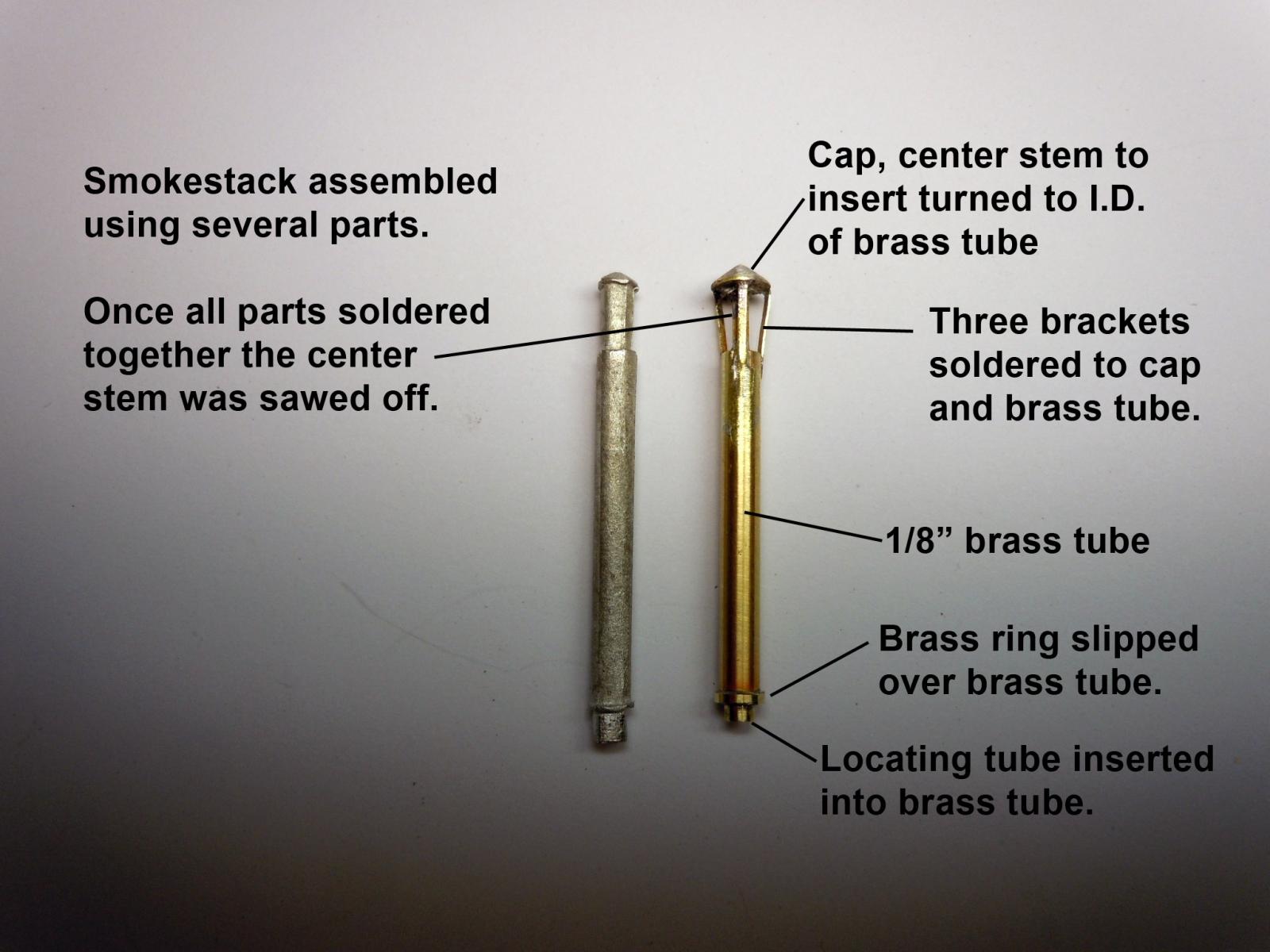
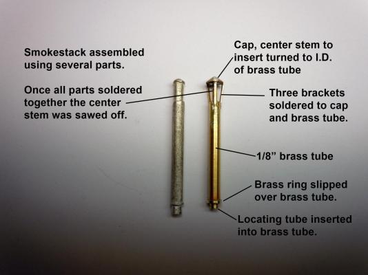
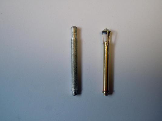
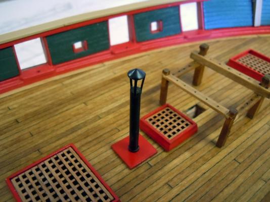
I was not satisfied with the smokestack casting in the kit so I decided to make my own. I made it out of brass which I am very familiar with. I started with a 1/8" brass tube cut to length, then turned a part having the cap a central stem to hold the cap to a turned insert fitting in the brass tube. A bottom ring was added as well as a locating tube to fit into the wood base. These parts were soldered together and then the three brackets were added being held in place with a binding wire and soldered to the brass tube and the cap. Then the center locating stem was then sawed off using a jeweler's saw rotated three times between the brackets. This shows it with the center stem cut away prior to painting and compared beside the kit casting. Here it is painted and in place on the deck. Ken
- 440 replies
-
- 6
-
-
- niagara
- model shipways
- (and 1 more)
-
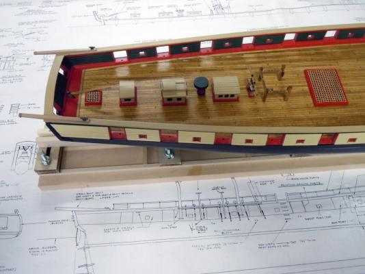
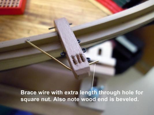
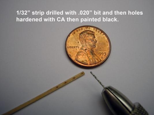
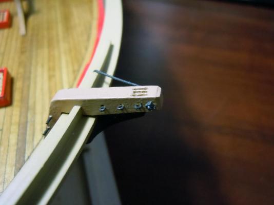
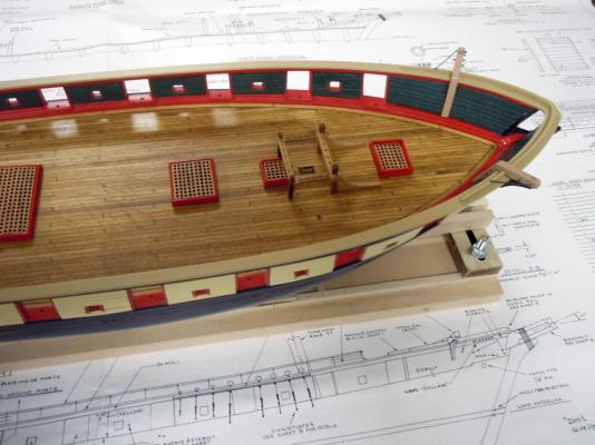
Had a break in building to get a honey-do done and installed an exhaust fan in a bathroom. I am sure that many of you know as well as I do that if momma ain't happy nobody is happy. I worked back and forth on the rear davits and the forward cat-heads. Here are images of the rear davits; a close up and an overview. The sheave slots were first drilled with a .020" drill bit and then holes joined with cutting using a jewelers saw and carefully cleaned with a sharp Xacto blade. The cat-heads were a little more complicated than the davits especially adding three sheave slots. The ends were also beveled with a sharp Xacto blade. Here is a better view of the slots that were drilled, sawed and trimmed with a sharp blade. Also the eye-bolts and rods were added per plans. One issue I had was that the cat-heads and other parts this thick were not laser cut as a left and a right instead of being the same. The laser creates an angle that becomes more pronounced on thicker wood and if sanded square generates smaller parts. This is a common mistake by designers not familiar with laser cutting. Once the cat-heads were glued in place after cutting a slot in the chock rail the brass rod brace was cut and fitted with an extra length shown in the picture to add a square nut (not shown on plans). The square nuts were made using a 1/32" strip that holes were drilled into and then hardened with CA before painting and cutting to size. Hex nuts were not invented until later at the end of the century. Here is a close up showing the square nut in place and also note the beveled ends. Here is an overall view of the cat-heads in place. Here is an overall view of the brig to date. Ken
- 440 replies
-
- 8
-
-
- niagara
- model shipways
- (and 1 more)
-
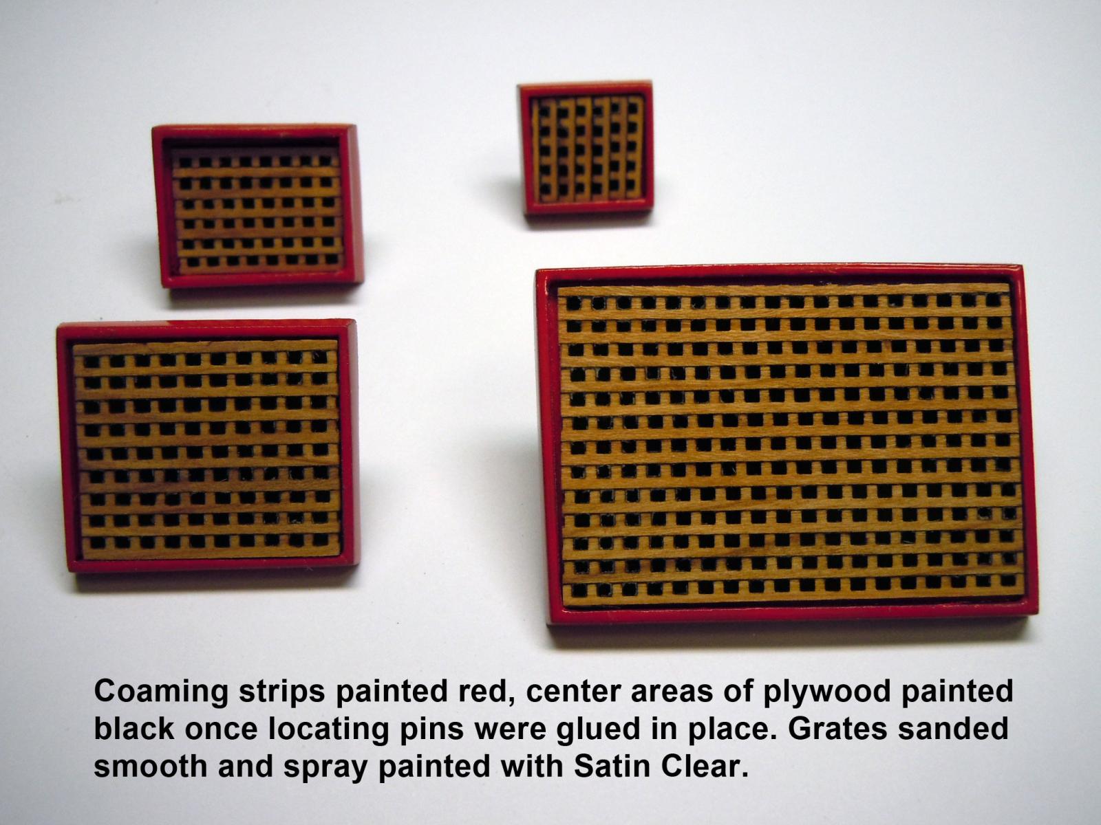
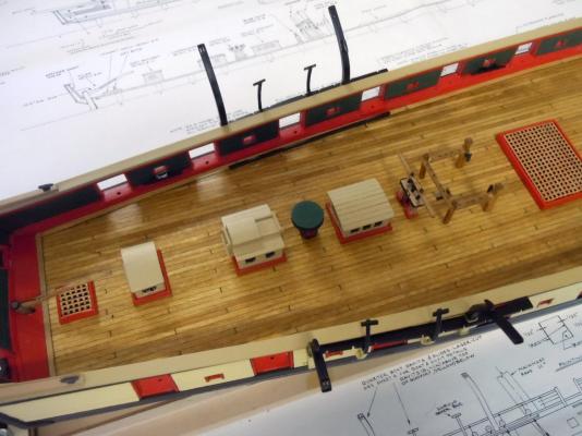
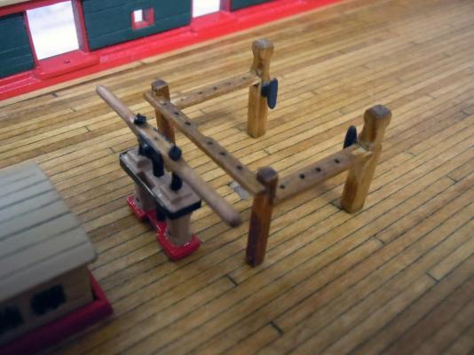
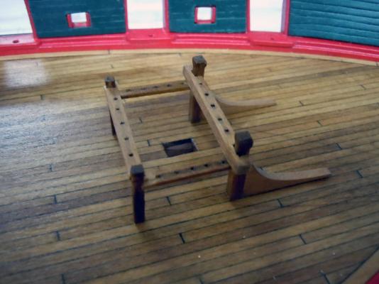
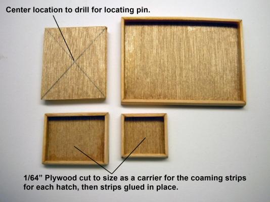
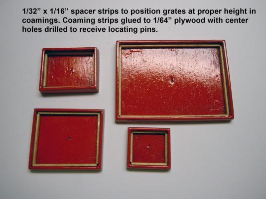
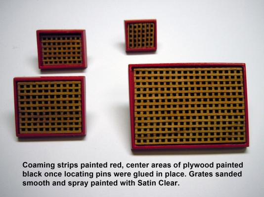
David, if it is not fun I would not do it. I got some work done despite it being mother's day and having fun with the grand kids and moms. Here are the fore and aft fife rails. I will add locating pins later once the masts are in position. I then started the deck hatches by first rough shaving a strip at the correct angle with my small plane and then sanding to final angle. I am told that there are people who love aggravation and I am not one of them; so I cut 1/64" plywood to the various sizes of the hatches to glue the coaming to. The corners were cut at 45 degrees with an Xacto blade. On the backside I marked the centers for location pins into the deck. They were then painted red and I discovered that stand off spacers were needed for the grating to be positioned correctly. I then added the spacer strips and they were hand painted red. Then the center areas of the plywood carrier were painted black. Then the grates were added. The grates were built by using the laser cut strips which were cut slightly oversize to the needed hatch and then glued together. I would recommend gluing the grate strips to each other by using yellow glue and a tooth pick to add a drop of glue to each of the standing cuts and then add it to the smooth side of the next strip. If you want to be truly aggravated to no end try using CA. CA is great for some applications, but not for gluing grates together. However, once the yellow glue was set and prior to final sanding and sizing I did add CA to the perimeter of each grate for extra strength while sanding. Here are views with the grates set in place using the locating pins and not glued in place just yet. Next I will work on the smoke stack, cat heads and aft davits. Ken
- 440 replies
-
- 7
-
-
- niagara
- model shipways
- (and 1 more)
-
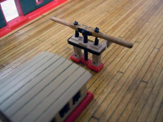
Steve, thank you for your comment and glad to hear you enjoy the posts. Finished up the capstan and located the deck and moved onto the bilge pump. Here are pictures of it on the deck; also a close-up of it. The trickiest part was the band around the posts. Next the aft fife rail. Ken
- 440 replies
-
- 5
-
-
- niagara
- model shipways
- (and 1 more)
-
Kurt, Thanks for the picture! I suspected it was to the rear for the vary reason you stated. Some things just make common sense. Thanks for the confirmation. Will have to go back later and do some surgery to add this detail. Thanks again! Ken
- 440 replies
-
- 2
-
-
- niagara
- model shipways
- (and 1 more)
-
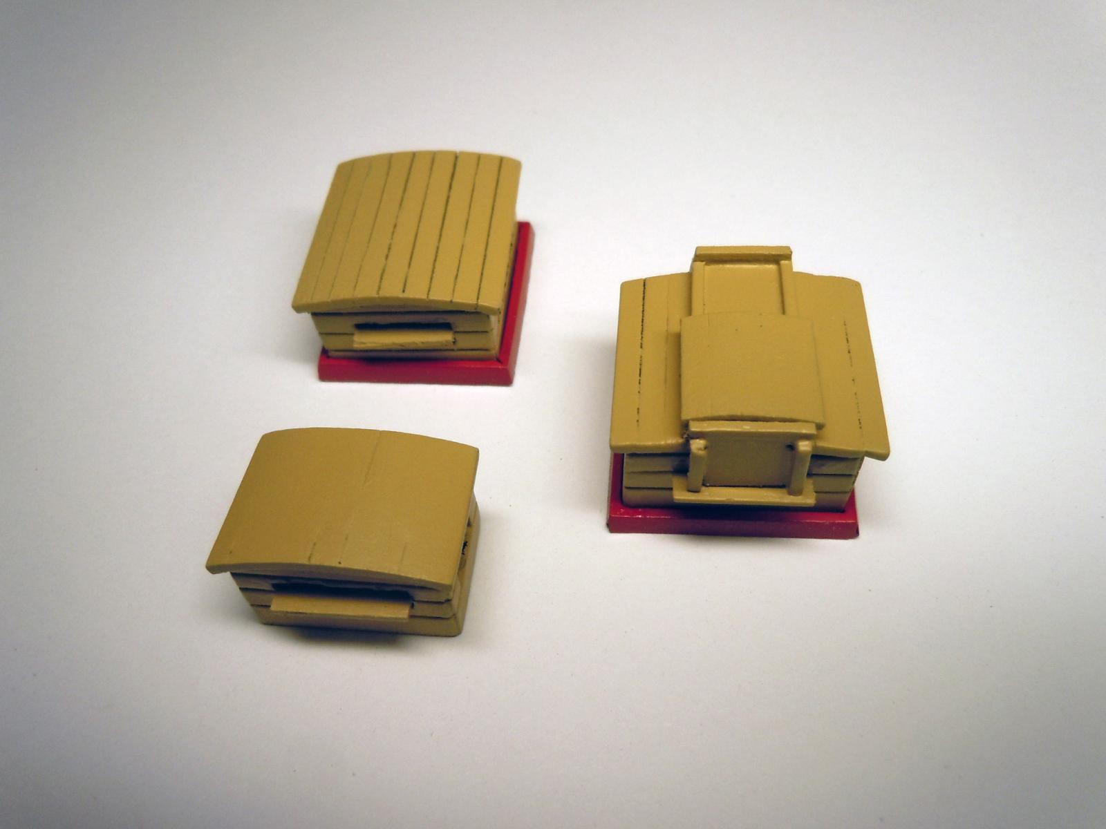
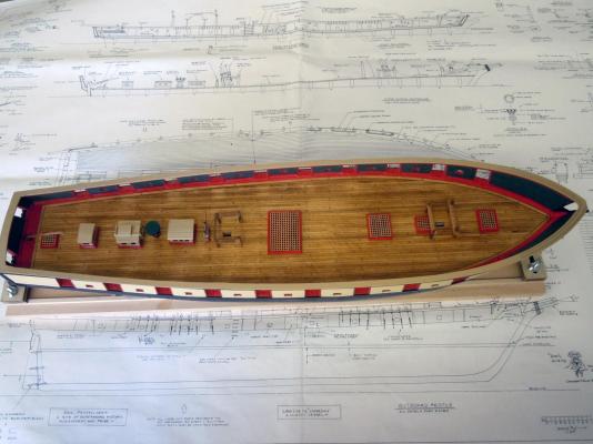
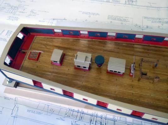
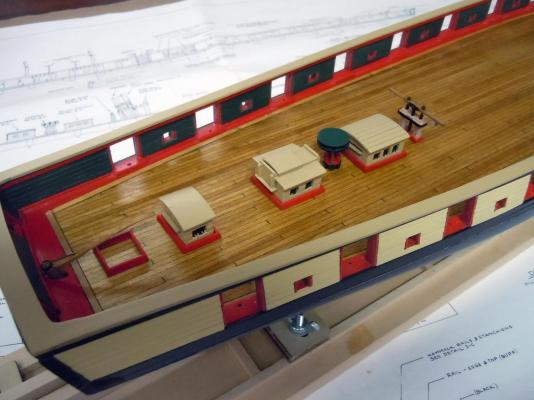
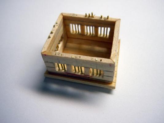
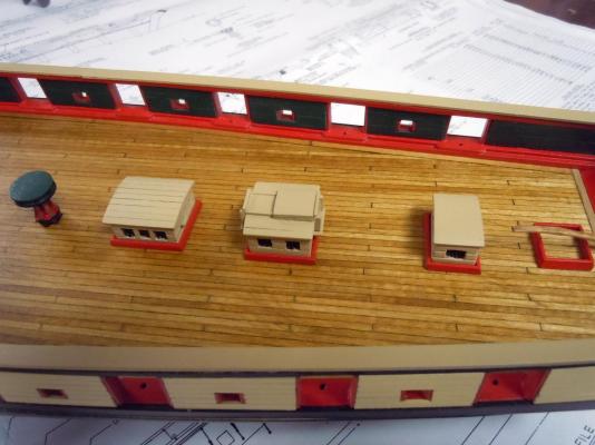
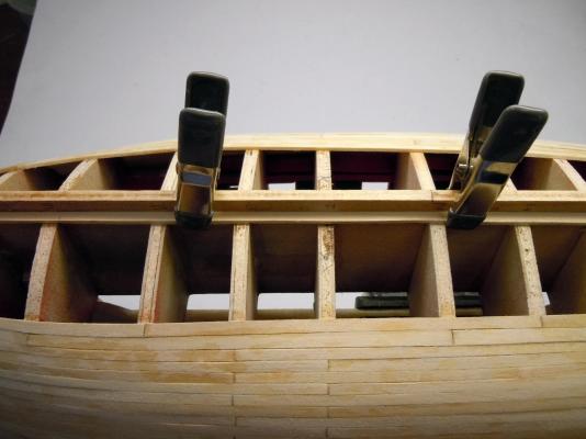
George, continuing on with the fun here are the start of the deck structures as I move forward. I have not yet built the wood grating and am building the coaming frames first. The first one is under the tiller. I built the structures as to the best I could with the plans and instructions and I built the center one with a sliding door which I think is correct. In building the structures with the bars I drilled the holes down through the bottom edge but only to the first section which allowed adjusting the bars to their correct position on the top section using fine needle nose pliers and pressing into place. This was a better option than trying to drill both and in the picture you can see a couple of errant bars due to drill misalignment that were corrected with needle nose pliers in final fitting. Here are the three built up structures with bars in place, but still needing a little cleanup tweaking in a couple of places. I find that closeup photos show things my tried old eyes cannot see while building. To build the curved roof rather than individual planking; I cut a rectangle slightly over sized, measured and marked where the planking widths were and carefully cut half way through the thickness. Then carefully cracked the cuts to curve and set on the structure and held in place adding CA to the cracked joints.(do not glue fingers to the roof) Once the CA set I turned the roof upside down and added a layer of CA evenly across the entire surface and let set. Once set I centered the roof on the structure and carefully trimmed down to proper size and glued in place. Here they are just set roughly in place on the deck with the capstan set into the mast hole since the dowel hole has not yet been drilled for it. The sliding roof section can be seen, but can anyone tell me if there should be an opening and which side would it be on; bow side or stern side? I know there has to be stairs leading below on one of them. Now to finish the capstan and move one up the deck. Ken

- 440 replies
-
- 5
-
-
- niagara
- model shipways
- (and 1 more)
-
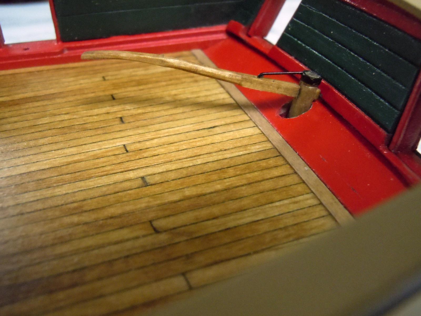
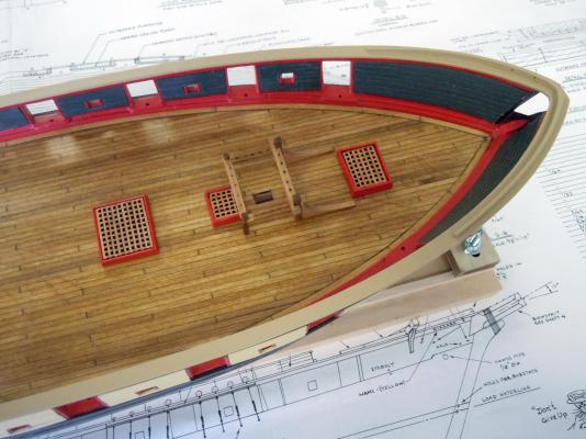
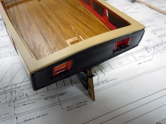
Here is the working tiller test fit and it works perfectly. It will be removed and clear coated. The hole in the transom deck had to be moved slightly to the rear due to the hinges on the rudder once finally fitted I will close up the hole on the rudder shaft. The wire brace was soldered to the metal ring on the shaft top and bent to index into the hole on the tiller. Here I have added the main rail once the chock rails were added at the bow. I assembled as a separate part for painting purposes to achieve a smooth even finish. As George said now the real fun starts! Here are the mooring chocks set into the stern windows. These were carved form a single pieces of wood stock then primed and painted before being added. Looking through the left window and below the tiller in the picture above can be seen the coaming of the lazaret hatch. I am starting at the stern and will move forward down the deck building the needed structures. While building these I will study the bowsprit and masts prior to building them. Ken


- 440 replies
-
- 5
-
-
- niagara
- model shipways
- (and 1 more)
-
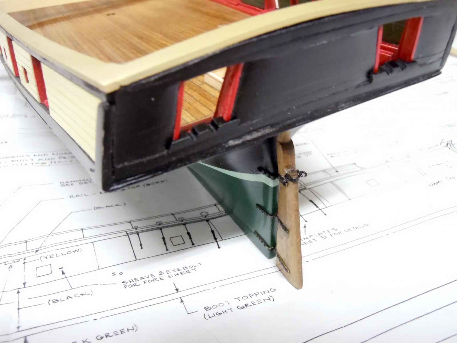
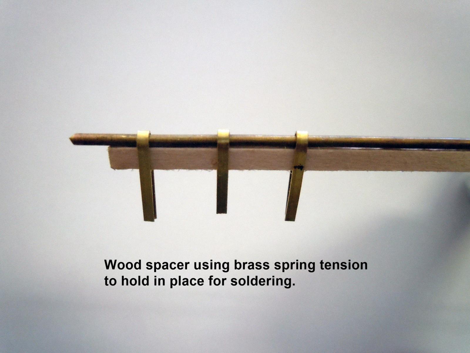
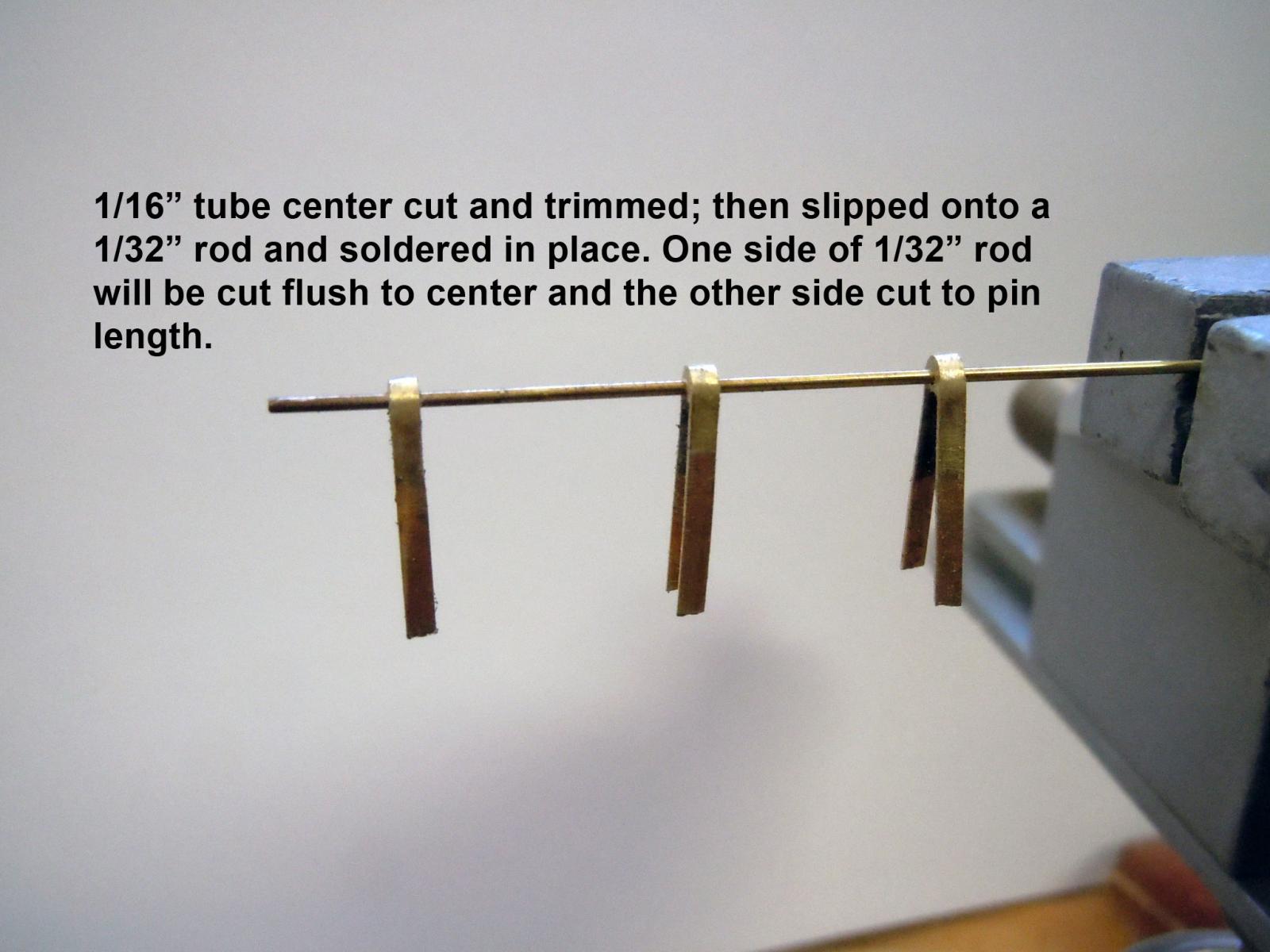
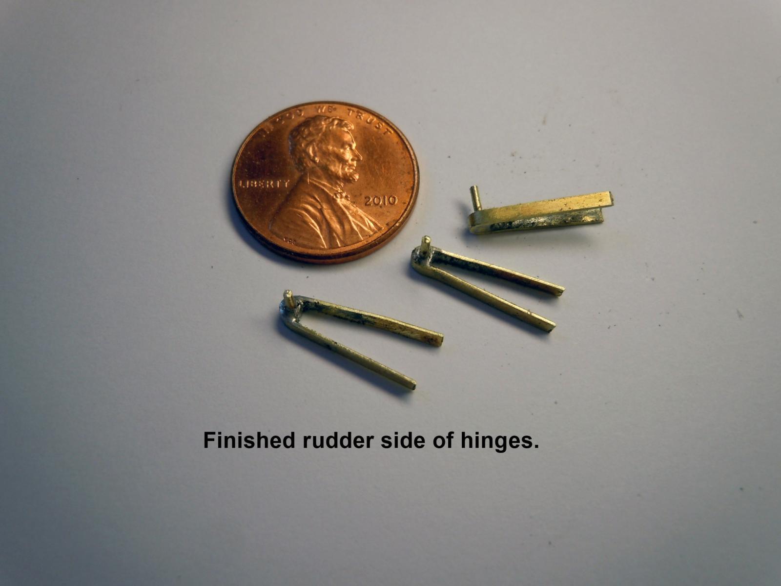
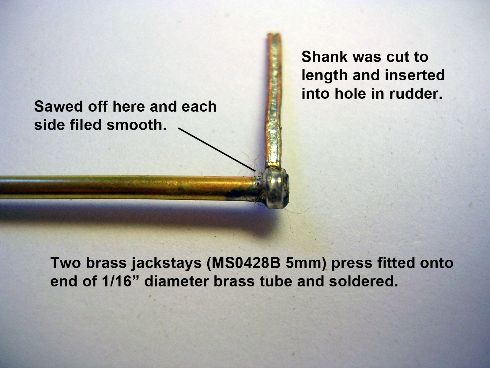
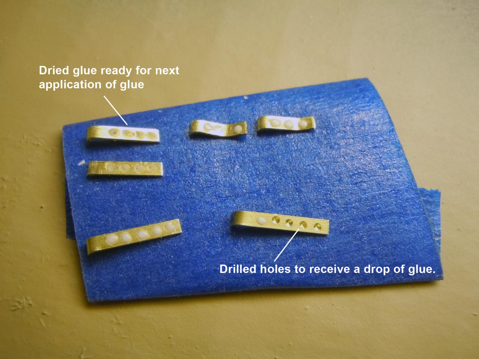
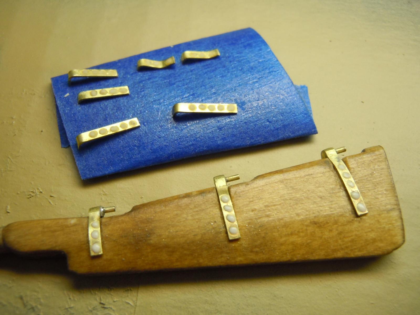
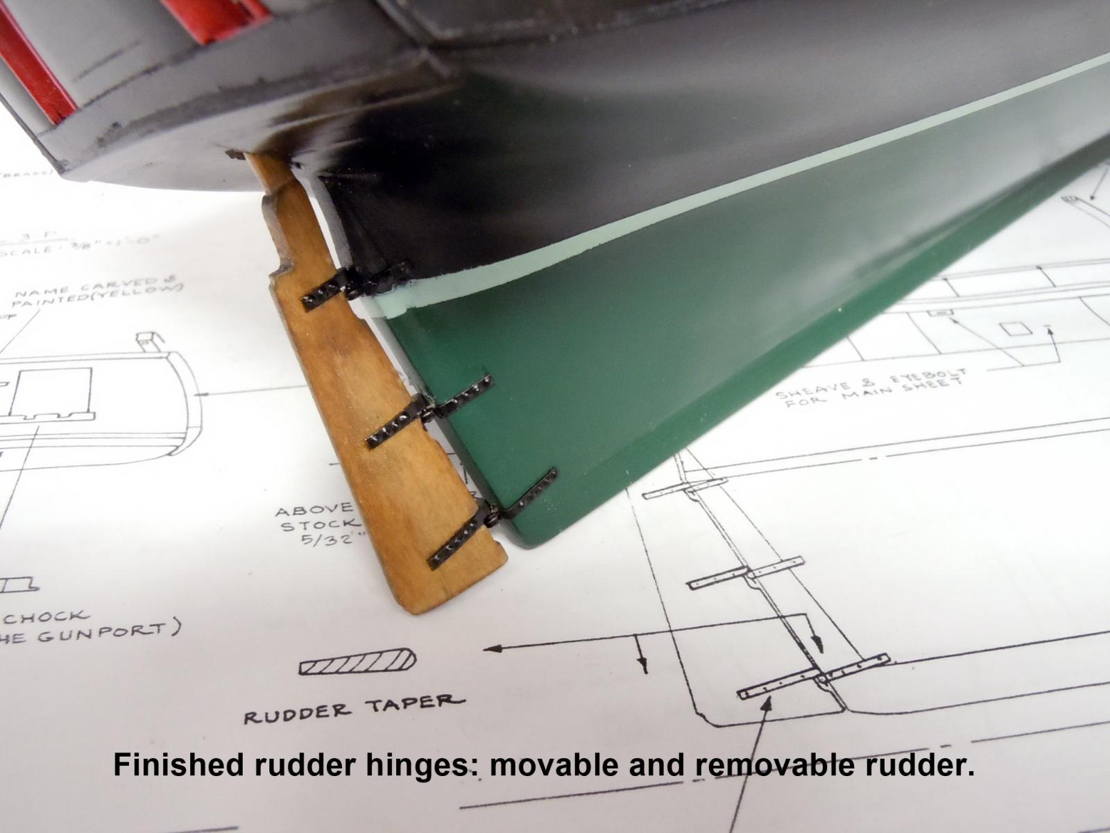
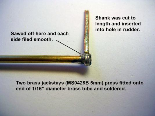
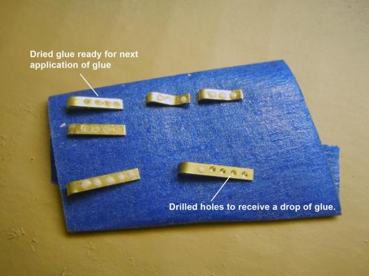
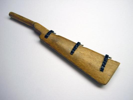
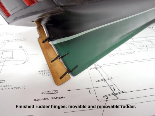
I moved on to the rudder and decided that I should make it movable; so here is a sequence showing how I built the hinges. First I formed the rudder side of the hinge by bending 1/16" strip over a 1/16" tube and used the spring tension in the bent strips to hold them in place while being soldered. Then the tube was cut and filed to the the edge of the strip and slipped onto a 1/32" rod to become the pin. Here are the finished rudder side of the hinge. The pins will allow the rudder to also be removable. Next I fabricated the stern side using a couple of jack-stays soldered onto a 1/16" tube and cut to form the female side of the hinge. The female side of the hinge were inserted into holes drilled in the stern. The stems were trimmed to 3/8" length. Care must be taken to locate the holes on center to have all the hinge pins line up. The rudder must move freely. Here is the test fit. Next I cut the straps for the stern side and drilled location holes for the bolt heads. I then mixed carpenters glue and water thick enough to hold a round shape when added to the holes using a sharpened toothpick. It requires several applications of glue drops until a round head is formed. The glue shrinks into the hole for a firm grip to the metal. This shows the straps and rudder finished ready for paint. This shows the painted rudder hinges. Here the hinges are in place and painted. The rudder moves freely and is removable for more work to be completed at the tiller end. Ken


- 440 replies
-
- 6
-
-
- niagara
- model shipways
- (and 1 more)
-
Excellent job! I will be stopping by for reference on my build underway. And you are correct about fireplace mantels. Ken
- 468 replies
-
- 2
-
-
- niagara
- model shipways
- (and 1 more)
-
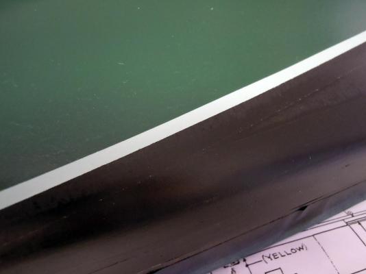
Here it is with all the masking off of it. Grant, yes that use of clear coats goes way back to my car painting days. I did custom paint jobs on cars and motorcycles for extra money. Looking through some of the builds here I saw a few bleeding edges so I thought I would share. Ken

- 440 replies
-
- 7
-
-
- niagara
- model shipways
- (and 1 more)
-
Kurt, George, thank you; I am starting to get a handle on ship building. Hopefully I can share some of the techniques I have learned over the years. Ken
- 440 replies
-
- 2
-
-
- niagara
- model shipways
- (and 1 more)
-
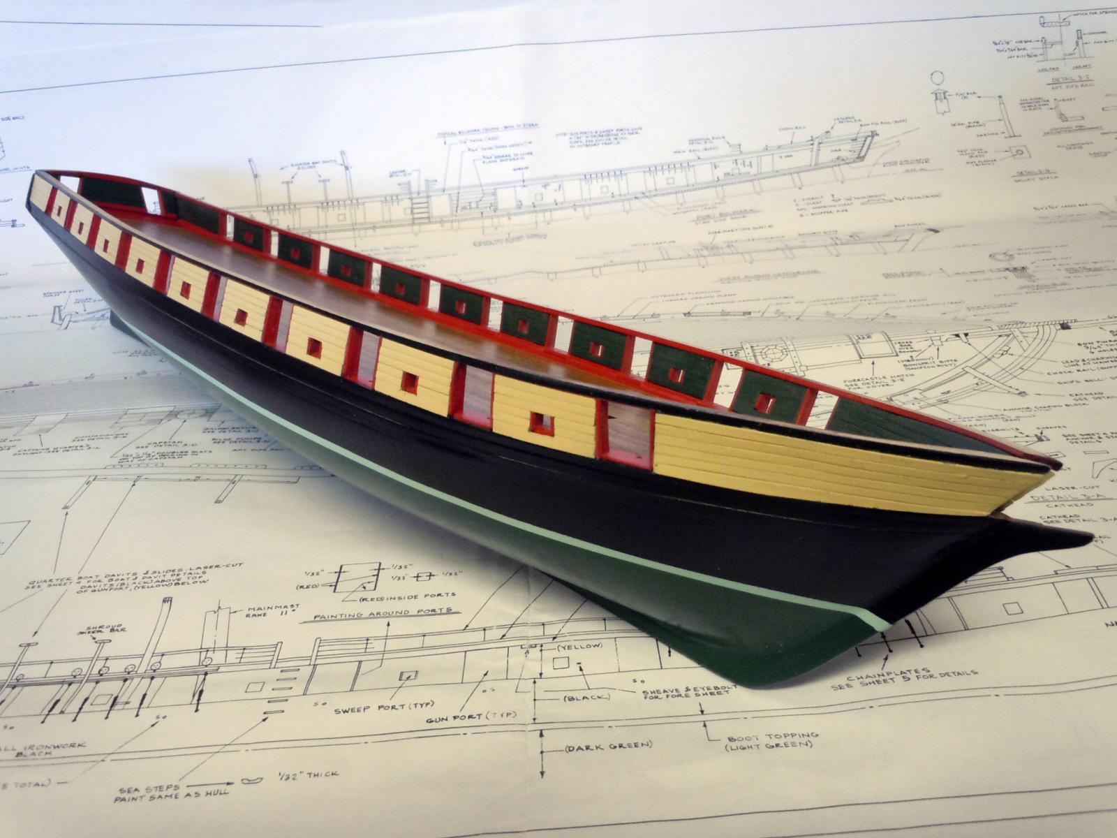
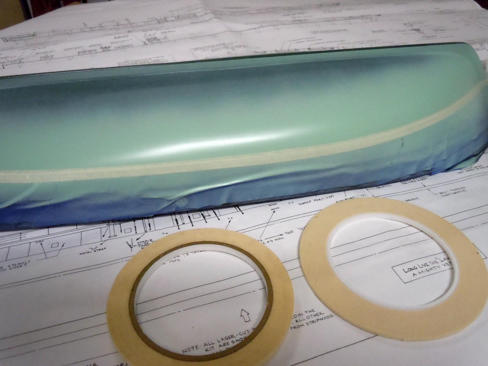
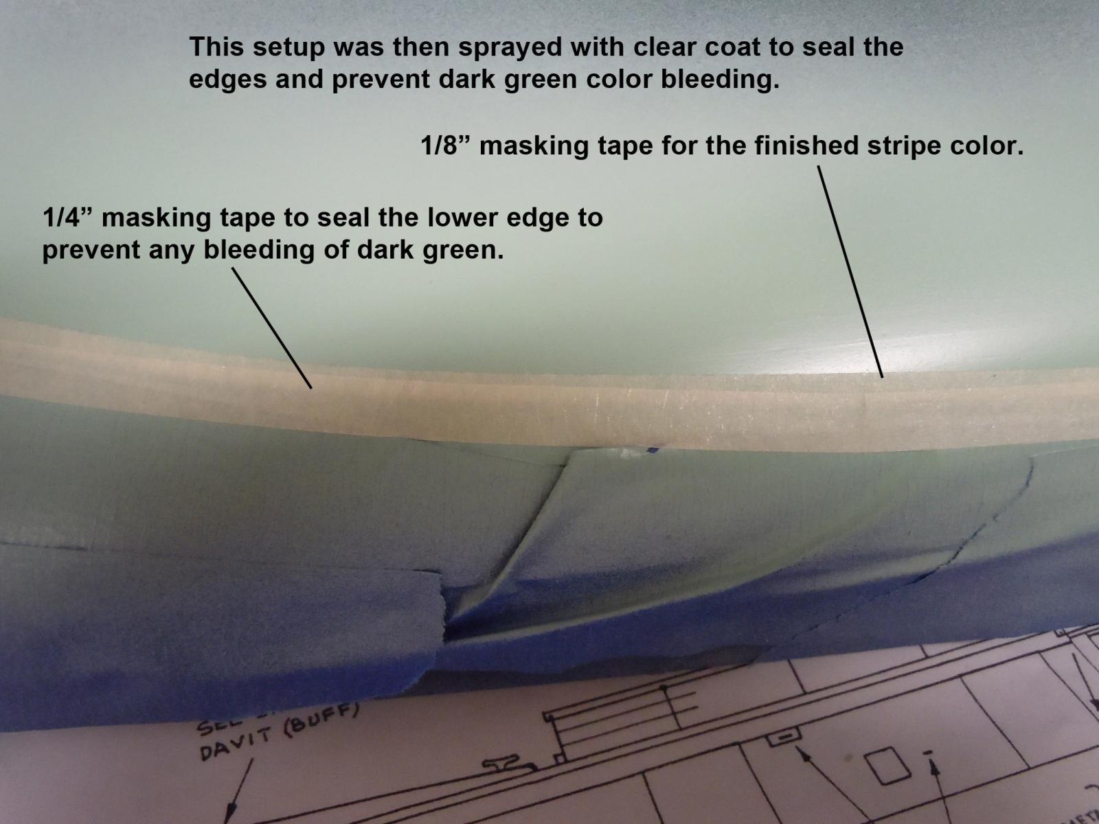
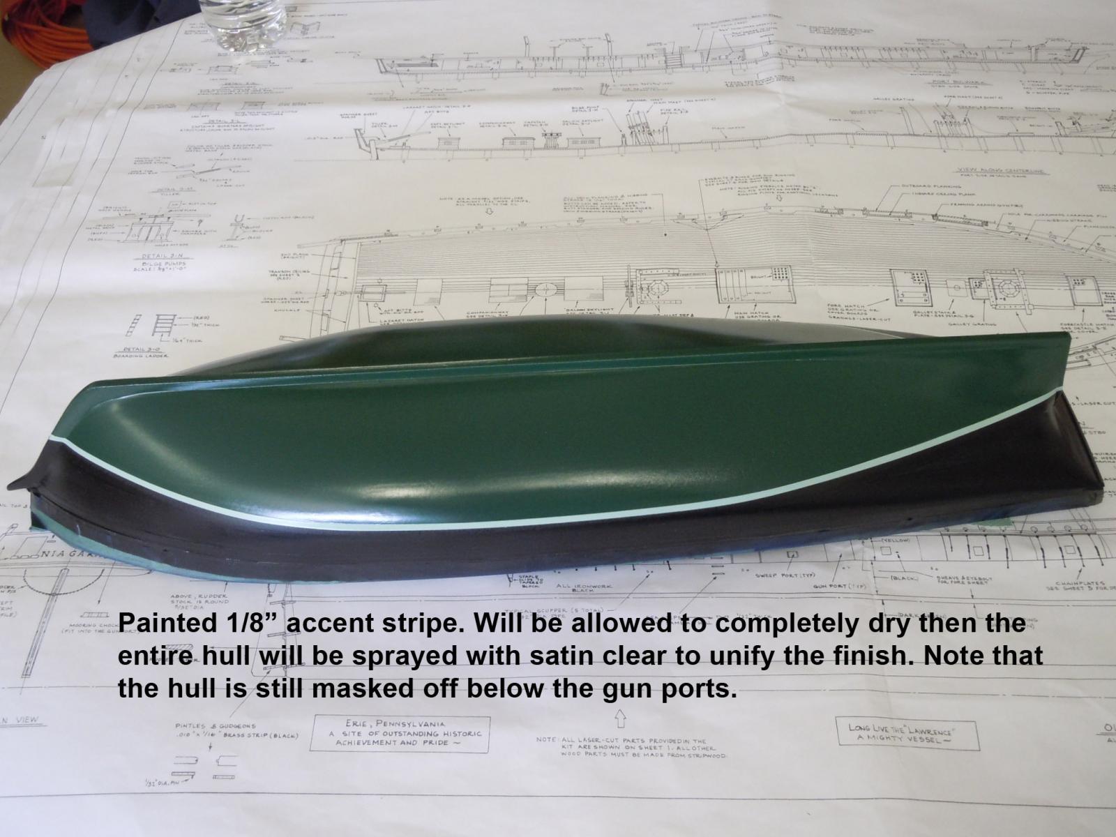
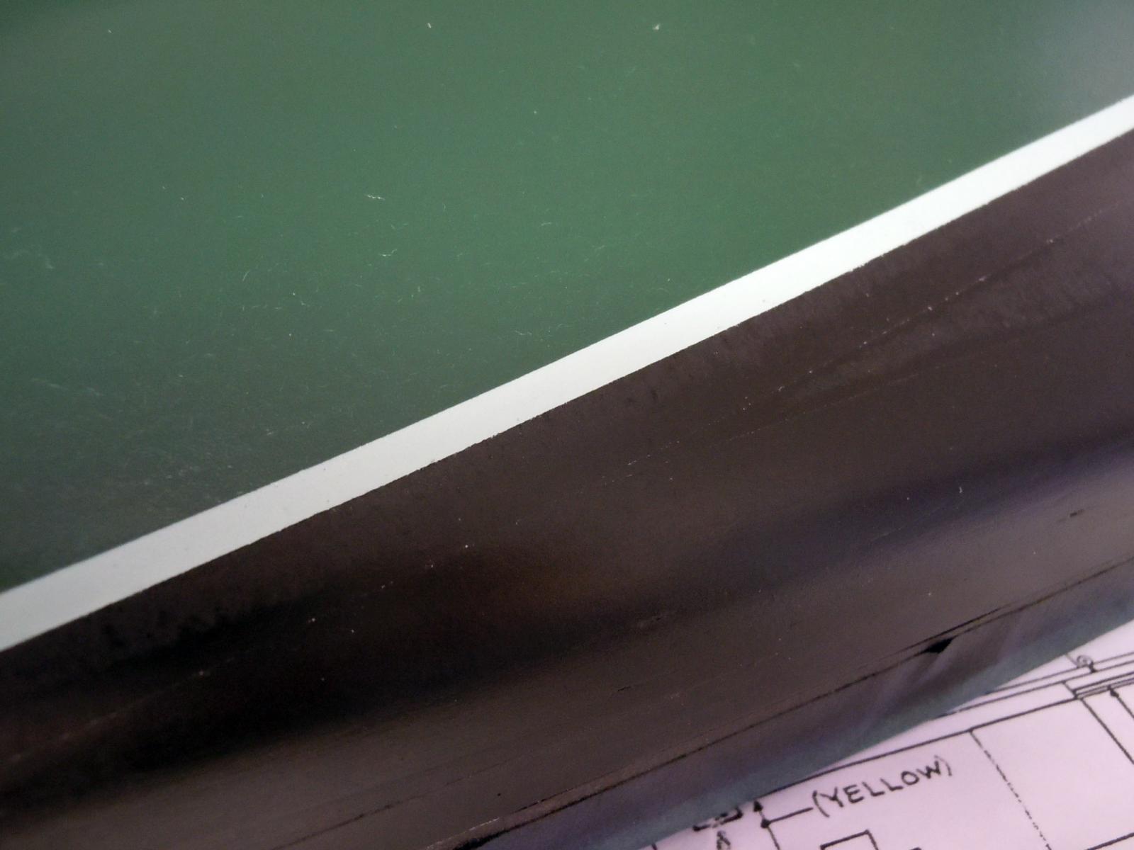
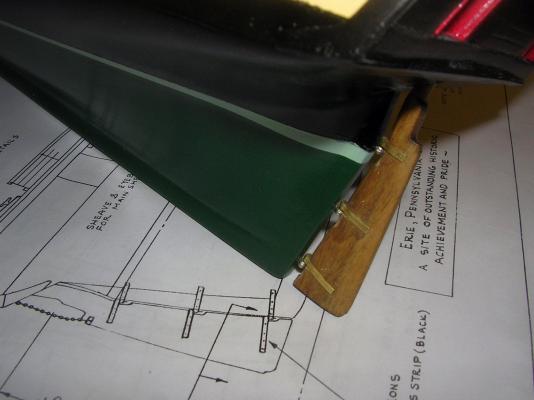
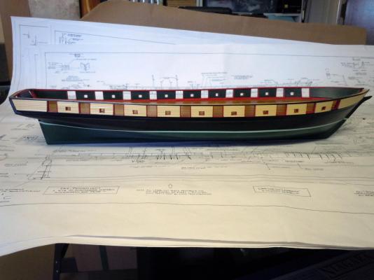
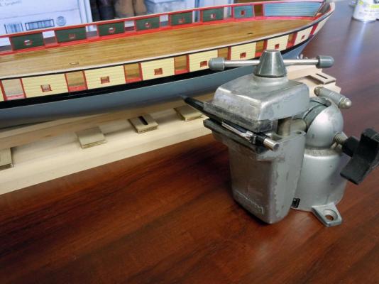
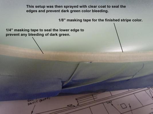
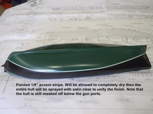
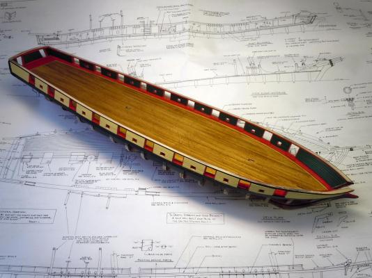
They say the necessity is the mother of invention. To that end I setup my panavise to hold a mechanical pencil to mark the top edge of the accent stripe and it worked perfectly. One thing to make sure is to mark a reference mark down from the gunports on each side and hold the hull steady while marking. Also have a slight upward angle to clear the aft section of the hull. The top section of the hull was masked off at the bottom of the gun ports to protect what was already painted yellow and red. Sorry no picture. Only one pencil line is needed since I am using 1/4" masking tape to define the finished stripe. The tape was applied very carefully to the top side of the reference pencil line. Once the tape was in place a couple of light coats of satin clear was applied to seal the masking tape edges and if any bleeding occurs it will be clear. The bottom half of the hull was masked off and the section from the line to the gunports was painted black and allowed to completely dry. Sorry no picture again. Once the satin black was set the masking was removed from the bottom; then the black edge was masked off with the upper black area being protected. This exposed the bottom half of the hull and the tape edge was sprayed clear to seal the edge and then sprayed light green. Let dry completely. The 1/8" tape was then applied very carefully to match the black edge. Once the 1/8" was completed a 1/4" was applied to seal the bottom edge of the 1/8" tape. Then clear was then added to seal the edge. Here is a closeup to show the tapes applied. Once the clear was completely dry (if clear is not completely set some crazing may occur) the dark green was sprayed. Once the dark green was dry enough to handle the masking tapes were removed except for the masking at the bottom of the gun ports; this will be needed for the overall clear spray. The reason for the clear being applied is to have as little or no color bleeding under the tape. Here is a close up of the end result. Nice clean crisp edges. Once all paints are completely set an overall satin clear coat will be applied. If any touch ups are needed do carefully with a brush before applying the clear coat. Now to work on the tiller while the paint sets. Ken

- 440 replies
-
- 6
-
-
- niagara
- model shipways
- (and 1 more)
-
Grant, Thank you for your kind compliment. I am going to paint the hull the colors next since I have devised the holder for it. Ken
- 440 replies
-
- 1
-
-
- niagara
- model shipways
- (and 1 more)
-
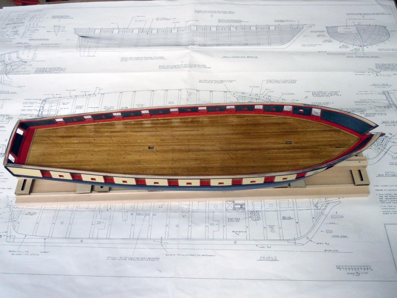
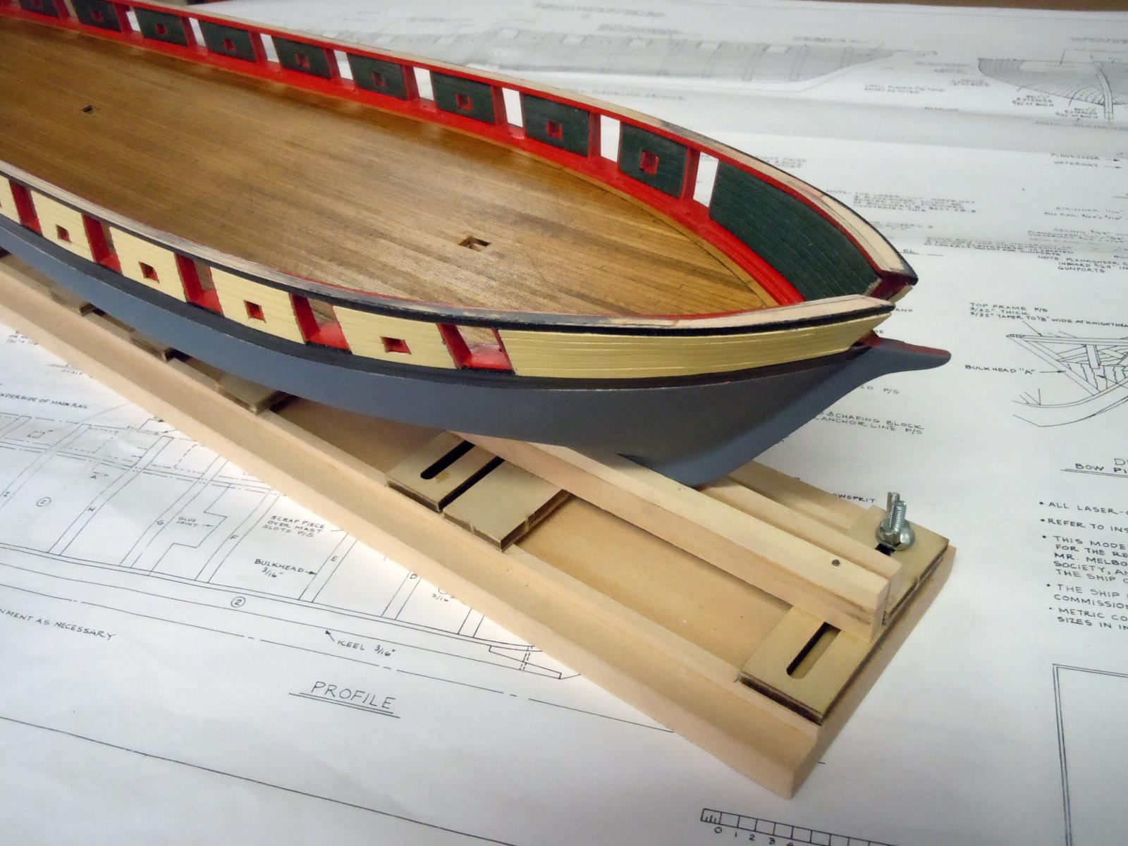
George, yes I think it will look great. Here are pictures of the hull clamped into the modified base of the Fair -a-frame. With this setup I can scribe the lines for the colors. I also just set in the deck which I will keep removable for a while. Next I will work on the top rail and decide what to do on the deck elements. Ken

- 440 replies
-
- 4
-
-
- niagara
- model shipways
- (and 1 more)
-
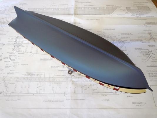
George, thank you for your comments. The plan calls for black from the gunports down to a boot topping line which is light green then a dark green below the light green line. So I will do it that way. I am debating whether to paint it now or wait until more work is done on it to avoid any damage during building. It is much easier to repair a primed finish than a painted one. This build has taught me a great deal in building the hull and I am in a much better position to take on the USS Constitution. Thanks again! Ken
- 440 replies
-
- 3
-
-
- niagara
- model shipways
- (and 1 more)
-
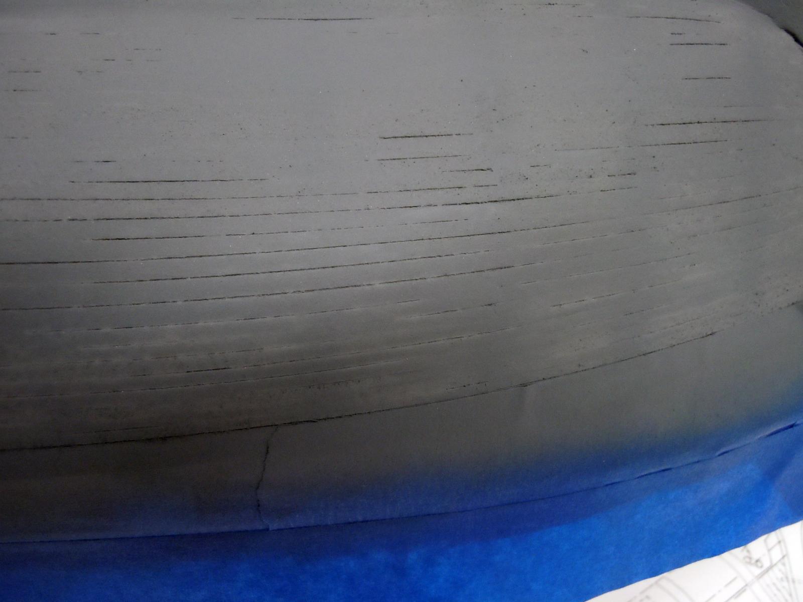
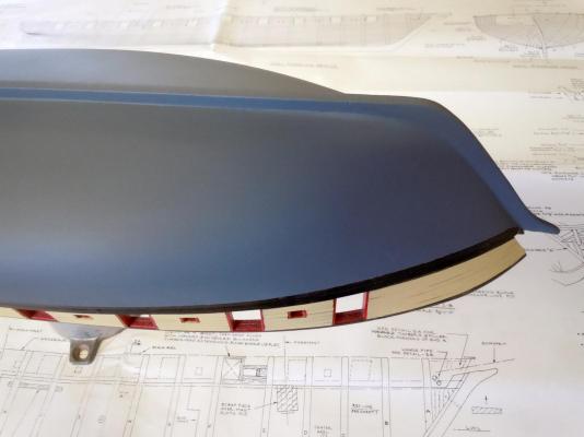
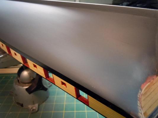
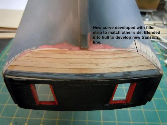
The glazed hull was sanded down, keep in mind that 95% of the glaze will be sanded off. Once sanded and any joints that needed glazing were filled and sanded. Here are pictures of the sanded hull. The planking joint lines have "ghosted" on the finished surface. I will leave them so that when painted they will still show and kind of replicate the finished real hull. The ghosted lines are hard to photograph, but is looking close some can be seen. If I sanded the hull again at this point I could end up with a very smooth surface finish. On sanding the hull curves always sand diagonally in both directions across the curved surfaces rather than fore and aft. This diagonal sanding reduces the chance of having flat areas on the finished surface. Next I rebuilt the transom area now having the planking butts to work with. First I added a thin strip the finish the ends of the butts. I then made a pattern to match the opposite side and added the needed filler section to match. I then sanded the hull to match and define the joint line of the hull and transom. Next the new transom will be primed. Then the hole for the tiller will be drilled. Ken
- 440 replies
-
- 5
-
-
- niagara
- model shipways
- (and 1 more)
-
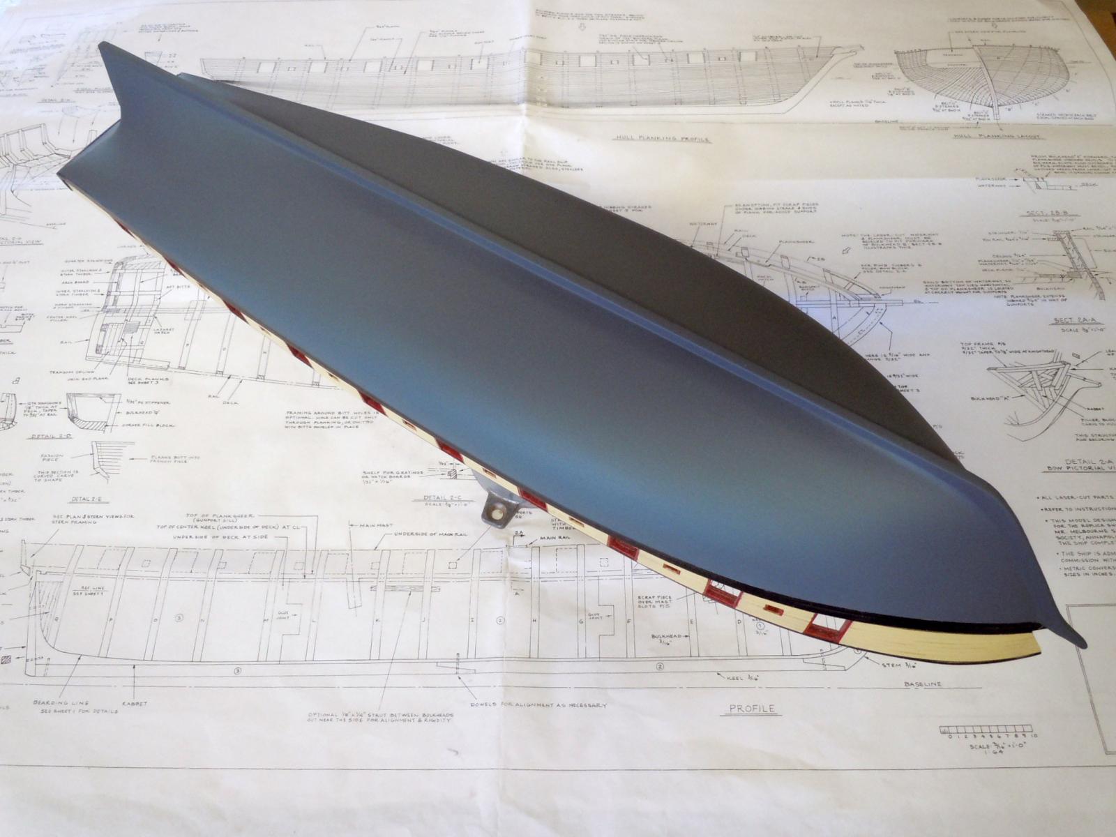
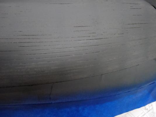
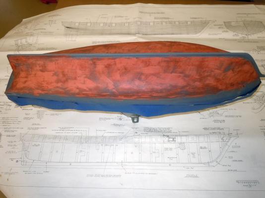
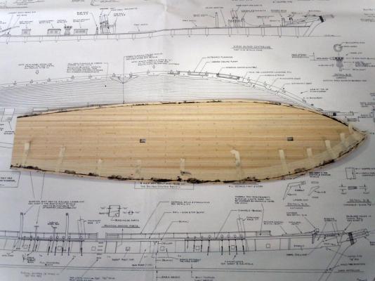
The hull planking was completely sanded using various grits of sandpaper to the point of looking and feeling great. Next I primed the hull using Krylon Gray primer to reveal all the gaps needing to be filled with glazing putty. I use the automotive glazing putty because of its softness in sanding to that of the wood density and it is fine enough to even fill sanding scratches. Here are bow and stern pictures of final sanding before priming. Here are the joint lines that show up once primed. Then I glazed the entire hull working one side first and then the second. Next I went back over the first just touching up any joints that the glaze shrank into. The glazing putty does shrink a little when drying. I use as little as possible just to fill the joints. Next will be the sanding off of the glaze once set. Some joint lines may still be visible and that will be fine since plank joint are visible on the real ship. Ken

- 440 replies
-
- 6
-
-
- niagara
- model shipways
- (and 1 more)
-
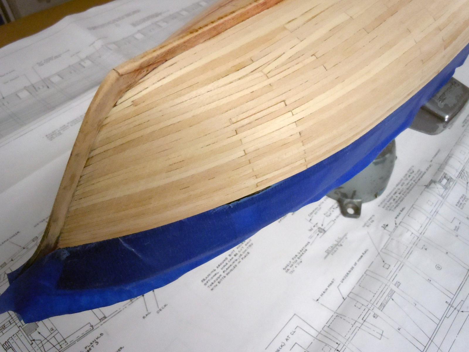
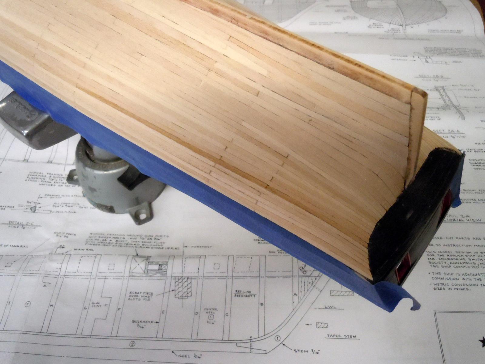
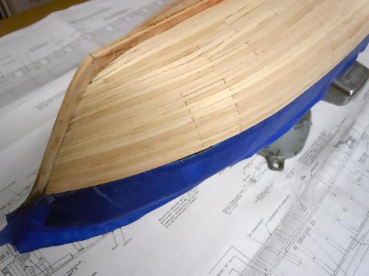
Finished up the rest of the planking between honey-do's. I am glad I had a little experience in planking airplanes when it got to the stern and bow areas and had to do some creative stealer work. I am glad that this will be a painted hull based on the butt joint patterns which I am sure are not to shipwright standards. It would have been very helpful if the plans had included a few butt lines to show the pattern. Please keep in mind this is my first ship build. Here are three views and some areas have had a little rough sanding done to them. Here is the bow area. And a stern view, the transition to the transom still needs a little fine tuning. Now to finish up the sanding and prep work for painting. Ken

- 440 replies
-
- 4
-
-
- niagara
- model shipways
- (and 1 more)
-
Eric, I spent 3 months aboard the USS Valley Forge LPH-8 1968 with Marine Helicopter squadron HMM-164. A few years back I remember a LPH plastic kit being offered on a limited basis through Micro Mark and I think it was the Tripoli. Have a great build and I will be stopping by to see your progress. Ken
- 176 replies
-
- 1
-
-
- new orleans
- iron shipwrights
- (and 2 more)
-
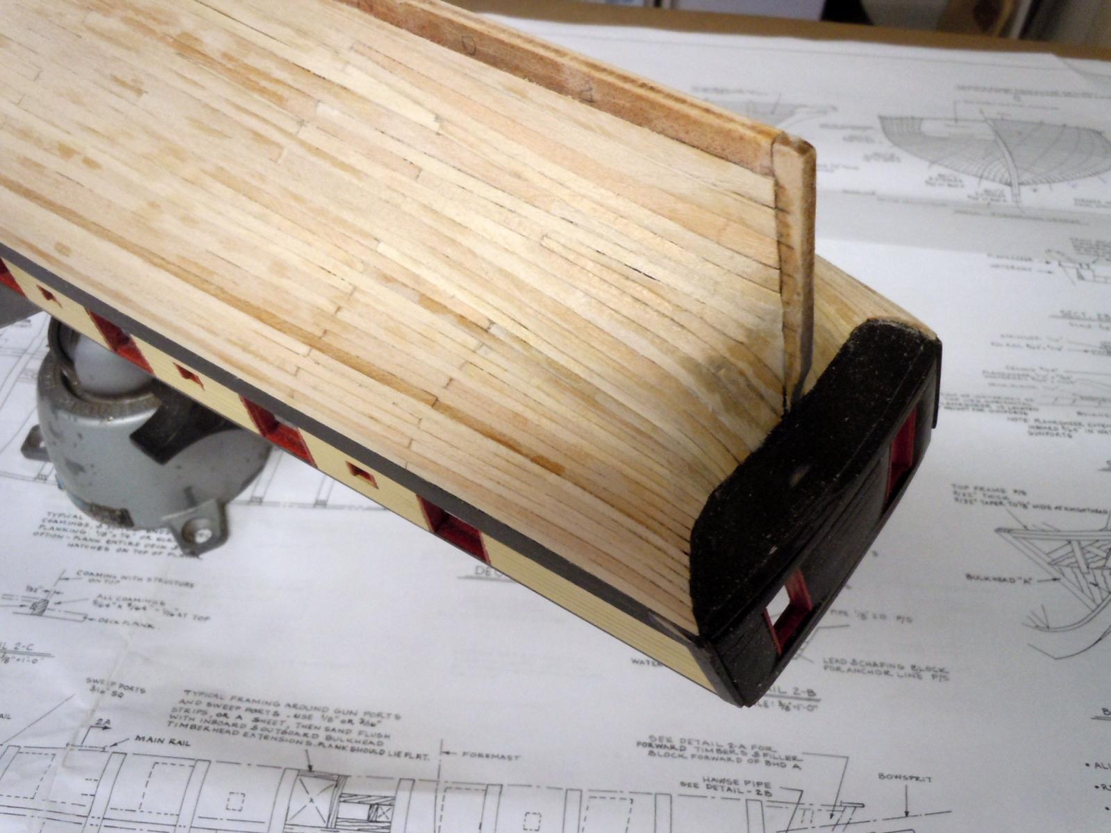
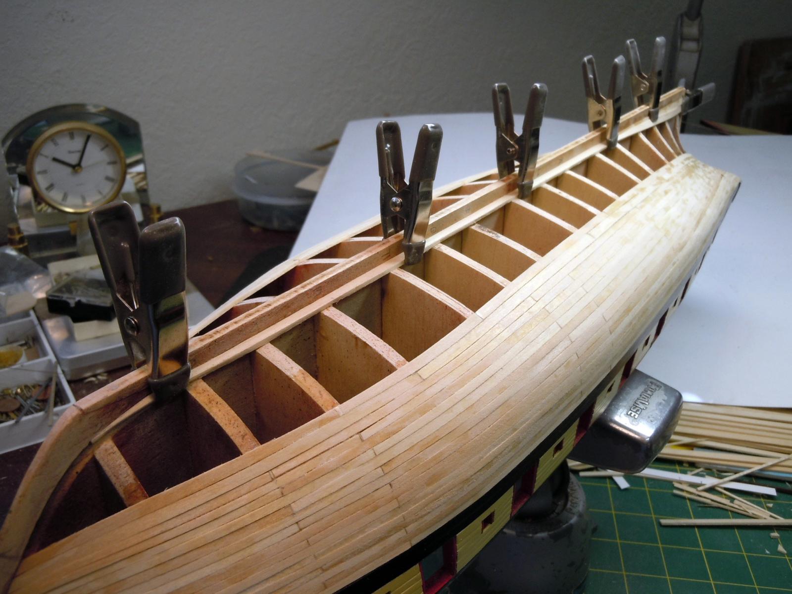
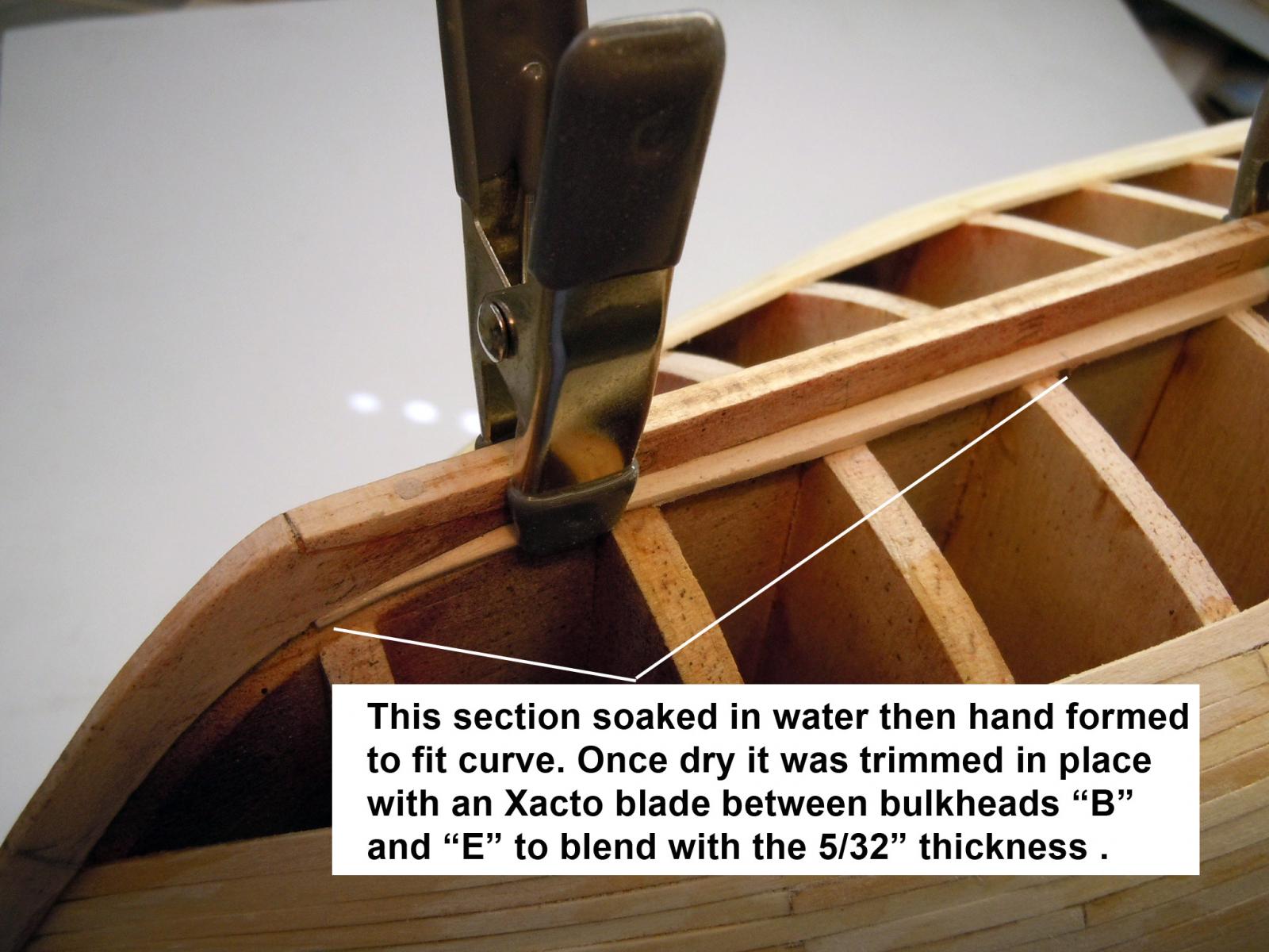
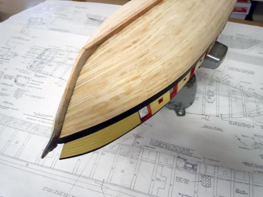
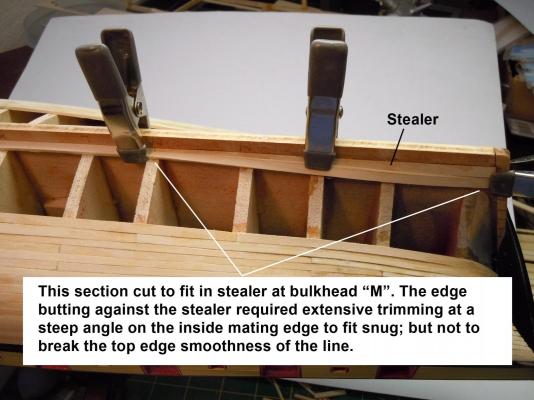
I have added the planking on both sides up through Belt "C" using the 3/16" strips supplied in the kit which were trimmed down to the 5/32" thickness on the plans at Bulkhead "H" and blended fore and aft. After installing two planks I thought it best to install the garboard which indexes into the rabbet at the keel and traps a stealer at the stern. After checking other builds I could not find how others did it; only finished hulls. So for the benefit of others who may follow and wonder as I did; right ,wrong or otherwise here is how I did it. First I cut and installed the stealer from bulkhead "M" to the stern. I then started with a strip of 3/16" and cut it to length from the stern to bulkhead "B" per the plans. I cut the shape out for the stealer while maintaining the full 3/16" width at the stern. Also while clamped in place I rough cut a curve from bulkhead "B" to bulkhead "E". The strip was removed and section "B" to just past "E" was soaked in water; once soaked it was then hand formed to match the curve of the keel and index into the rabbet. Once the curve was fitted the entire plank was then clamped in place to allow the curve to dry and set. In the meantime while clamped from "B" to "K" to allow the stealer cut out section to flex this inside edge that mated to the stealer was cut and trimmed on the inside at a steep angle to match against the stealer. Be careful not to cut the top edge and disrupt the smooth edge line. See pictures below. Here is a close up of the bow area at bulkhead "B" with garboard end indexed into rabbet. This shows the center section with 5/32" width exposed at bulkhead "H". This shows the stern section with the stealer glued in place with the plank clamped to allow the front to dry. Now back to planking and honey-do's. Ken


- 440 replies
-
- 4
-
-
- niagara
- model shipways
- (and 1 more)
-
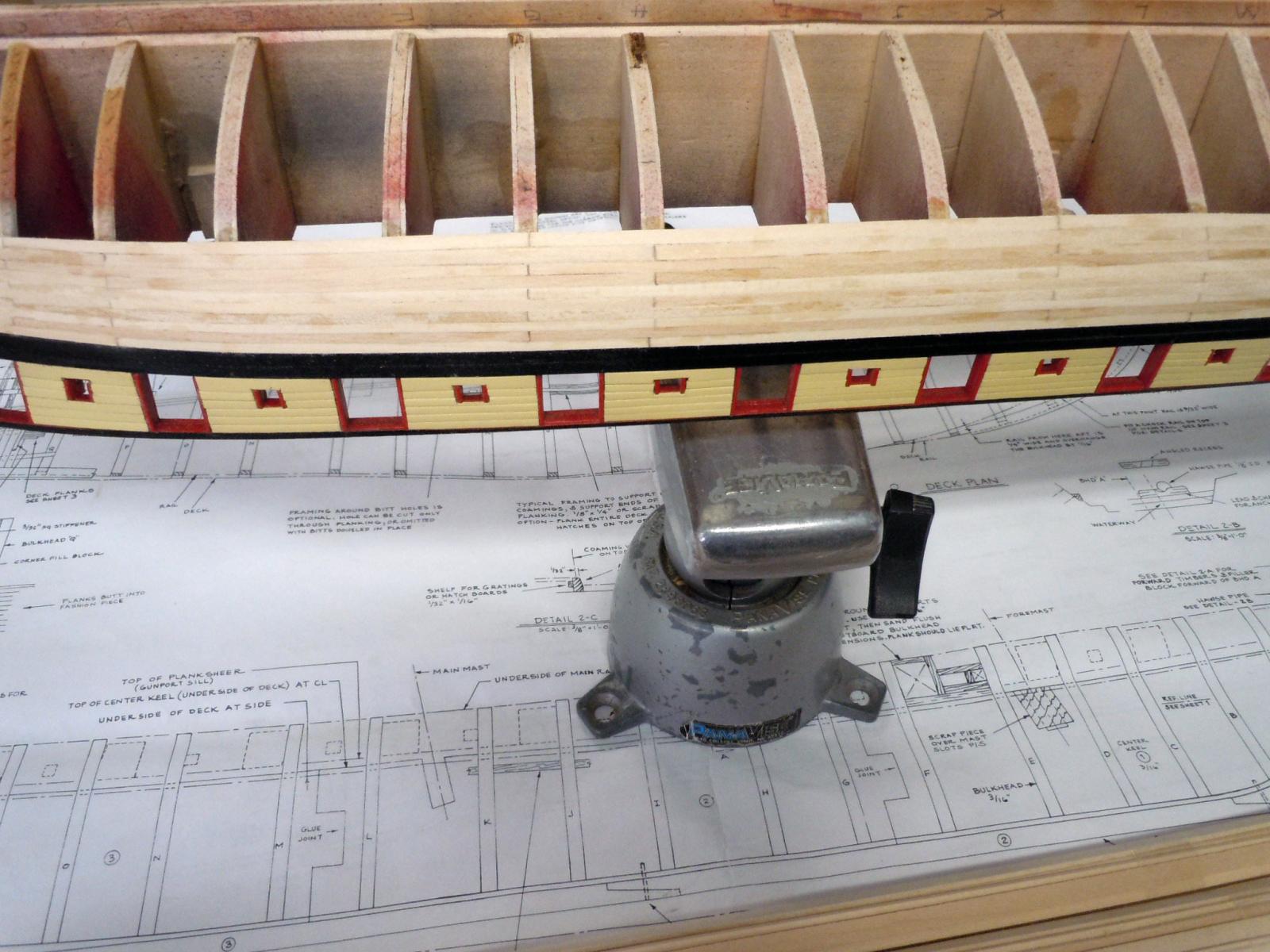
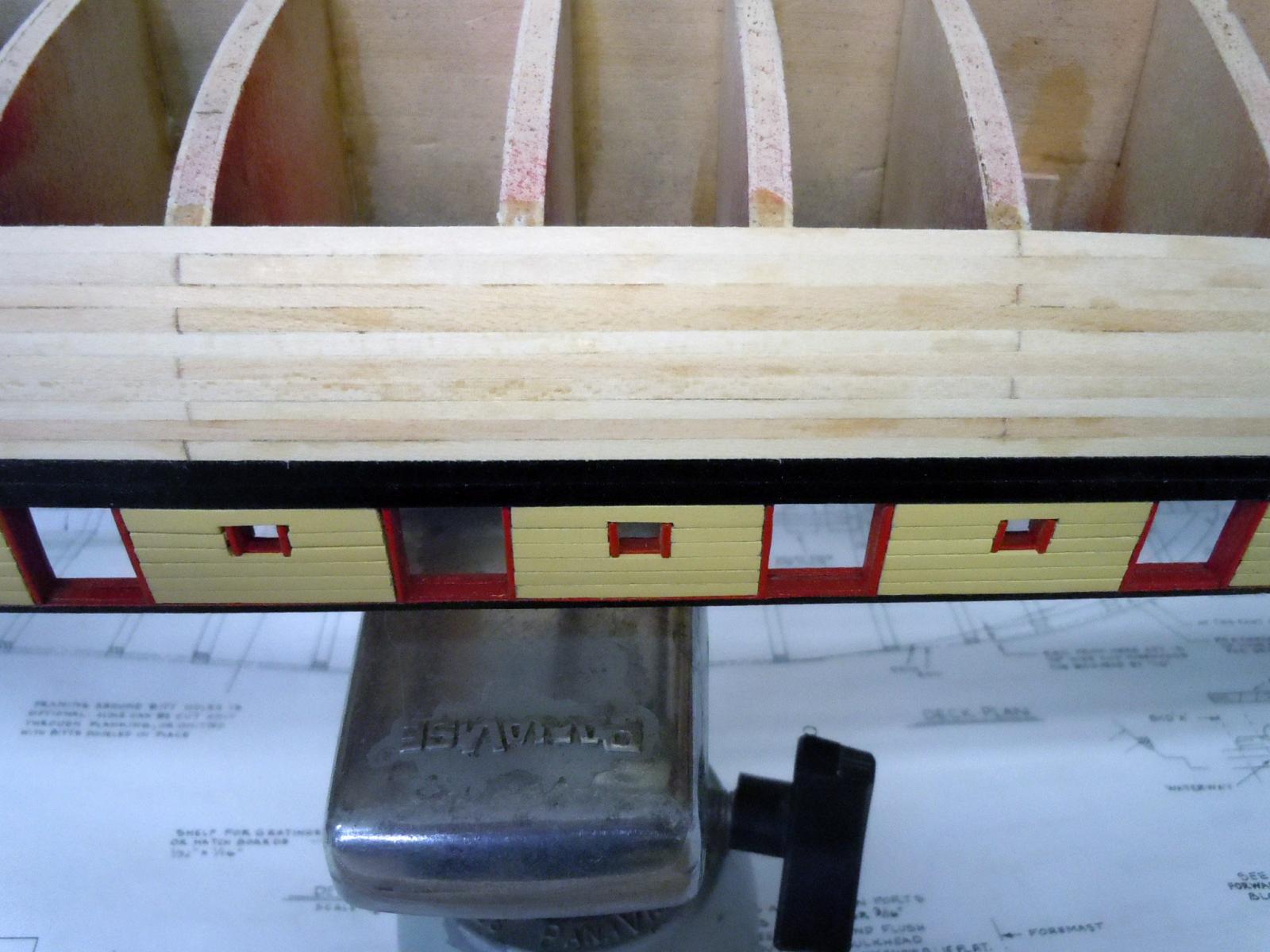
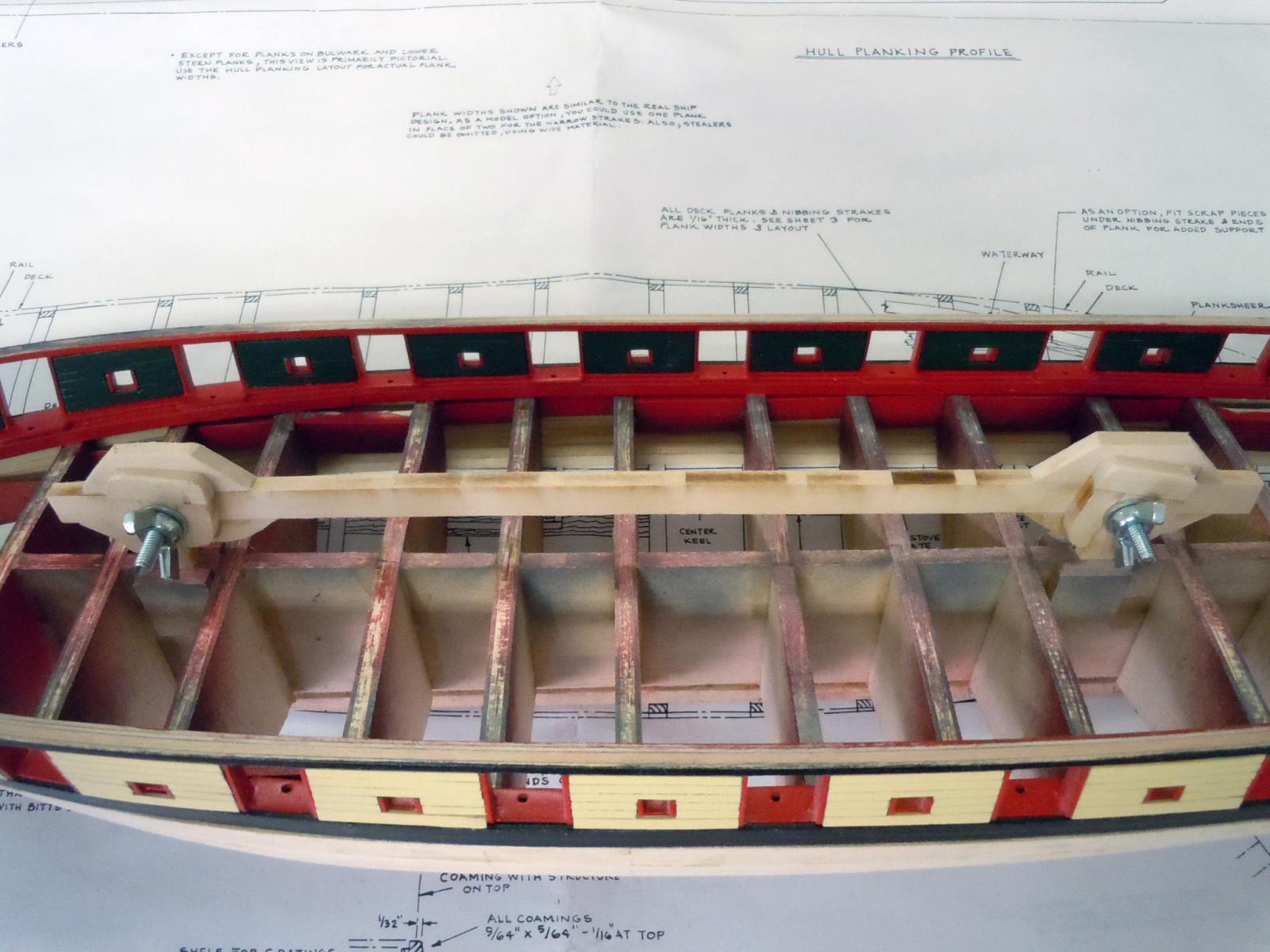
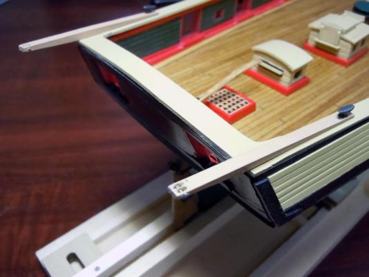
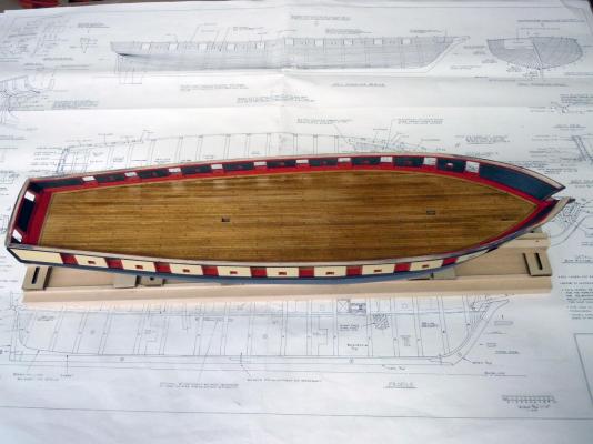
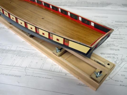
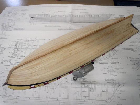
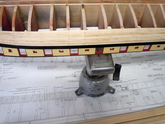
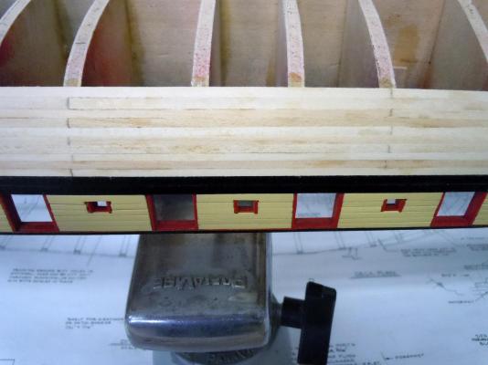
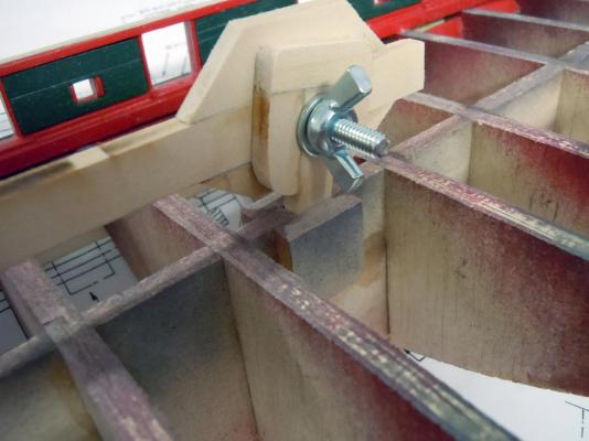
The deck has been painted with clear urethane and set aside for later use. Now I have started the planking of the hull. For me this is a similar process I have done before with airplane fuselages and wings and attention to detail and understanding what is happening to each piece will result in tight fits and thus minimal use of filler. Unfortunately, the thicknesses of the wood strips does vary that will require additional filler at certain places rather than excess sanding resulting in flat spots. Before starting I made a hull holder that clamps into my panavise and adjustable. I used the scrap 1/4" wood from the laser cut sheet. Not fancy but very effective and saved some money. Here is an overall view for the benefit of others that may build this ship in the future and save money. I used the mast holes with the parts being cut to a loose press fit. I salvaged the machine screws and wing nuts from the fair a frame unit. Here is a close up of the fit to the mast holes. Here are a couple of pictures of the hull planking at the center section. I followed the instructions and used the lengths recommended and they are working very well. For the tapering I am using my mini wood plane and the widths on the plans for the bow and stern and adjusting as needed. I am into the second belt at this point. Here is a close up, my goal is the minimal use of filler. However there are varying thicknesses within the wood strips that you may see in the pictures. Back to planking. Ken

- 440 replies
-
- 5
-
-
- niagara
- model shipways
- (and 1 more)
-
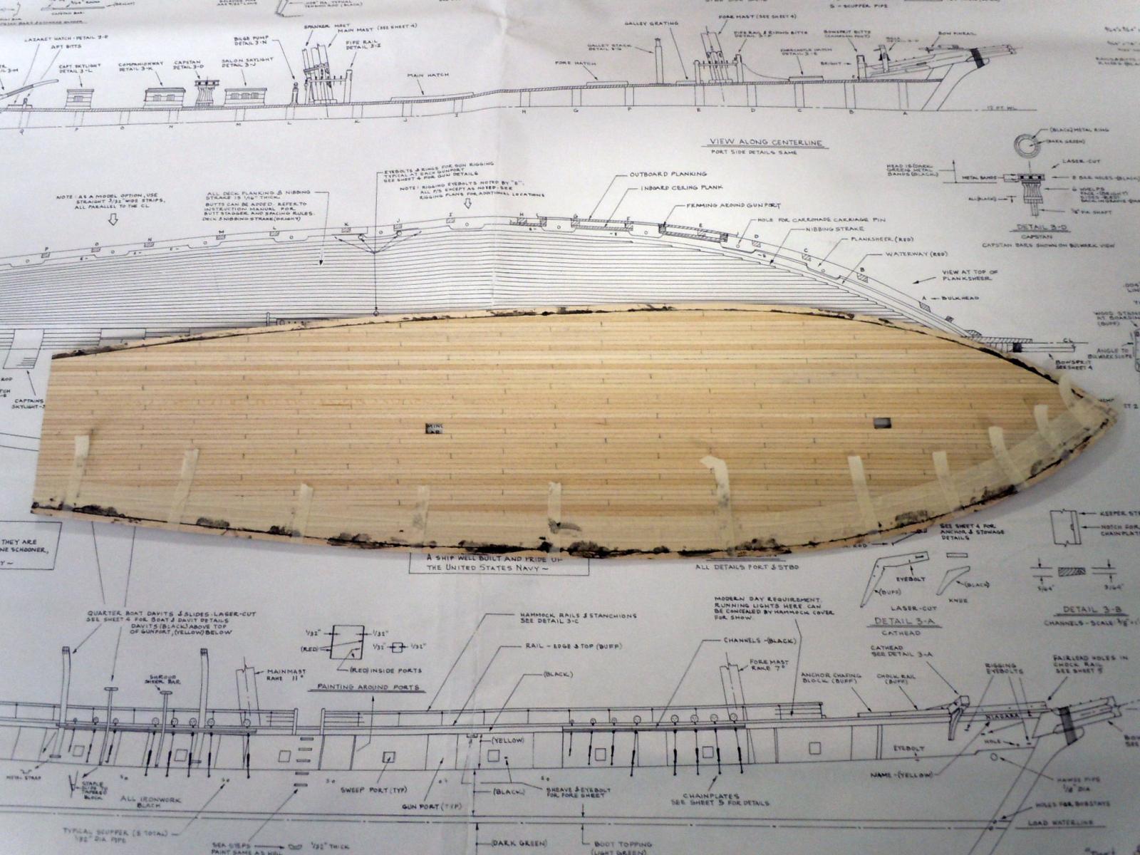
After fitting and a little fussing the second strake was glued to deck edge with the black glue and 1/4" masking tape to hold in place. Here the deck with sanded starkes is final fitted with a slight press fit. Here is the deck stained with Golden Oak and now drying before being clear coated. Now to sort out the hull planking. Ken

- 440 replies
-
- 4
-
-
- niagara
- model shipways
- (and 1 more)