


xken
-
Posts
841 -
Joined
-
Last visited
Reputation Activity
-

 xken got a reaction from Der Alte Rentner in USS Constitution by xken - Model Shipways - Scale 1:76.8
I have just finished up the main mast yards which were pretty much a repeat of the foremast. But After checking around I thought I would better explain the rigging of the trusses in more detail for the benefit of others that may be as confused as I was at first trying to understand the plans and my inexperience as a ship builder. The pictures are self explanatory and the most difficult part was the rigging of the truss block above the fighting top.
Here are the royal and top gallant yards in place.
Here I am setting the topsail yard.
I found that setting a long strip on the fighting top rail flush to the rail's back edge I had a great reference for setting the yard in space both up and down as well as fore and aft while the glue set on the locating pin inserted in the mast.
Here is the sequence showing the rigging of the course yard truss based upon what I think the plans were trying to explain.
Now on to the mizzen mast yards and then all the yard brace lines before adding the mizzen boom.
-

 xken reacted to kurtvd19 in Trireme Olympias by Richard Braithwaite
Richard:
Yellow Ochre powder can be mixed with water or alcohol and "Painted" onto the surfaces where you do not want solder to flow onto during soldering operations. Let it dry and then apply your flux and solder the part. I always use alcohol because the alcohol / yellow ochre solution dries much quicker than when water is used.
Yellow Ochre is a flux repellent and where the flux won't go neither will the solder. The solution can be kept in a small jar or other lidded container and if it dries between uses just add water or alcohol to make it liquid again. This will greatly reduce the amount of clean up needed after soldering.
I learned about this from Ken Foran's book Modeling With Brass - the 2nd edition has an added section on ship modeling using brass. In my opinion this book belongs in every serious modelers collection - but only after it has been read cover to cover.
Take care,
Kurt
-
 xken got a reaction from Der Alte Rentner in USS Constitution by xken - Model Shipways - Scale 1:76.8
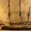
Back from the NRG Conference and I think my presentation was well received as well as participation in the round tables. I had a chance to meet and see the work of many great ship builders and sold out of the books I took for sale.
Getting back to work I continued on the canopy frames for the aft hatches and turned many stanchions, as well as, drilling them for their appropriate positions. Following is a series of pictures showing them being fabricated much as the same as the forward ones were made; of course no two were the same configuration.
An overview of the hull so far.
Next I will add the step plates on the deck and frames as needed and then onto the masts.
-
 xken got a reaction from Old Collingwood in 1869 Allerton Steam Pumper by gjdale - FINISHED - Model Trailways - Scale 1:12
Just for information on background of the original pumper. This is the second project I did with M.E. and probably the most complicated kit they ever made compounded by communication issues and personnel turnovers that continue to this day. I will not be surprised if this kit is discontinued due to the increase in cost of the Britannia metal. In reading through the build many of the issues may be a result of material substitution. On all the kits I design for them I build a "proof of production" of actual laser cut and cast metal parts using the instructions which are edited during the proof build. Unfortunately, once turned over to their production things happen. Grant you did a fantastic job on this build and glad to hear the Admiral enjoys it. Would be great to see a picture in the case on display.
https://www.destinationnaugatuck.com/historical-society/pistols-pins-fire-engines-built-in-naugatuck-ct
-
 xken got a reaction from Canute in 1869 Allerton Steam Pumper by gjdale - FINISHED - Model Trailways - Scale 1:12
Just for information on background of the original pumper. This is the second project I did with M.E. and probably the most complicated kit they ever made compounded by communication issues and personnel turnovers that continue to this day. I will not be surprised if this kit is discontinued due to the increase in cost of the Britannia metal. In reading through the build many of the issues may be a result of material substitution. On all the kits I design for them I build a "proof of production" of actual laser cut and cast metal parts using the instructions which are edited during the proof build. Unfortunately, once turned over to their production things happen. Grant you did a fantastic job on this build and glad to hear the Admiral enjoys it. Would be great to see a picture in the case on display.
https://www.destinationnaugatuck.com/historical-society/pistols-pins-fire-engines-built-in-naugatuck-ct
-
 xken got a reaction from gjdale in 1869 Allerton Steam Pumper by gjdale - FINISHED - Model Trailways - Scale 1:12
Just for information on background of the original pumper. This is the second project I did with M.E. and probably the most complicated kit they ever made compounded by communication issues and personnel turnovers that continue to this day. I will not be surprised if this kit is discontinued due to the increase in cost of the Britannia metal. In reading through the build many of the issues may be a result of material substitution. On all the kits I design for them I build a "proof of production" of actual laser cut and cast metal parts using the instructions which are edited during the proof build. Unfortunately, once turned over to their production things happen. Grant you did a fantastic job on this build and glad to hear the Admiral enjoys it. Would be great to see a picture in the case on display.
https://www.destinationnaugatuck.com/historical-society/pistols-pins-fire-engines-built-in-naugatuck-ct
-
xken got a reaction from Der Alte Rentner in USS Constitution by xken - Model Shipways - Scale 1:76.8
Have been working off and on with helping with the kids renovation project and babysitting the grandchildren to get them away from loud equipment. But in the meantime did some work on the deck structures and here are some progress photos of the steering wheel, binnacles and aft skylight. These are somewhat small items scratch built from wood with the exception of the cast steering wheel parts that were painted and stained.
Here I used .035" rope around the axle and into the rope leads at the deck.
Here is a sequence of the binnacle using a .032" rod for center alignment and indexing into deck.
Here are the brass shrouds with a polished finish.
Finished up ready for installation.
Here is the aft skylight that required many angle cuts and a sacrificed core for the upper framing.
This is the base unit.
Here is the sacrificed wood core with framing being glued to it.
This shows the cutting away of the core before the bottom framing is added.
This shows the individual wood parts and before the brass bars were added to the upper cap.
Here is a test fit and I think I will paint the inside of the lower base white, and the deck plate steel gray.
Now back to work.
-
xken reacted to kurtvd19 in Model Building With Brass
I love this book. Every time I pick it up I learn something. Have both versions and I think it is a must have for anybody planning any work with brass. It will save you time and lower your stress.
Kurt
-
xken reacted to GGibson in Model Building With Brass
Almost posted this comment in the Shore Leave - "What Did You Receive Today?" section, but then saw, almost eight years-to-the-day later, where Kurt Van Dahm had the above post regarding this book, so decided to add my comment here.
In preparing for my Constitution build, I have been researching and reading numerous past and existing build logs here on MSW. One of those completed build logs I've been reading is by @xken, Ken Foran. And in one of the posts in his extensively detailed Constitution build log thread was mention of his Model Building with Brass book. So... I had to have it!
This one is a 2nd Edition, copyright 2018. As someone who has struggled a bit in the soldering world, I am really looking forward to reading Ken's book and learning as much as I can. For as well as Ken has described his techniques in his Constitution build log, I have no doubt that, even after reading this book once, it will be pulled off the shelf multiple times after as a continued reference for working with brass in this ship building hobby. Thanks, Ken!
-
 xken got a reaction from abelson in US Brig Niagara by xken - FINISHED - Model Shipways - Scale 1/64
Spent a little time learning about oars; but could not find any details on how they were stowed in the boats so I used my judgement. Rather than one big bundle I split them into two bundles and lashed to the seats on either side of the tackle.
I also documented the process I used to fabricate them for the benefit of other novices like myself. I used the 1/8" square basswood strips supplied in the kit. I would have preferred to use a harder wood like maple for lathe turning since the basswood was stringy and soft. Slow gouging, sanding and patience was needed. Also to help I hardened the live center end of the strip with CA to keep the live center in place.
I setup my Sherline lathe to use the gouge cut on the backside and the front cut for the 90 degree shoulder for a reference point when cutting the blade. A picture is worth a thousand words so here are several showing the process from start to stowed.
Now to finish up some minor details and build a temporary base.
-
xken got a reaction from abelson in US Brig Niagara by xken - FINISHED - Model Shipways - Scale 1/64
Here is the application of the Niagara name to the bow and the stern. The stern had to be added before rigging the yawl. This were printed using the artwork above on photo paper at 300dpi.
Here is the port bow name.
Here is the stern with a slight arc; keep in mind that once the yawl is added not much of this is seen.
Here I am adding the canvas straps that hold the yawl. First I glued the end of the strip to the top surface and then wrapped it around and glued in place for an overlapping joint. The strips are white fine canvas sprayed with starch and ironed so it could be cut with a sharp blade for a 1/16" strip.
The strips were then wrapped around the yawl and up and over the rail and attached the the upper ring on the stern bulwark. To tie the knot to the ring re-wet the strip to make it pliable and easy to tie.
Next came the two cutters. First I add the canvas rub strips to the wooden slide battens. Then I tied .018" rope to the davits using a clove hitch half way between the cleat and the end sheave. Wrapped the ropes around the cutters while suspended in place and tied a clove hitch to the round section of the davit brace and cinched up to hold the cutter parallel to the water level.
Here is a close up showing better detail.
This shows an overview of all in place.
Now to make up the oars for them and any other details like the 20 sweeps which are mentioned on the plans, but no information on where they were stowed. Ideas on where they ought to be stowed would be appreciated, or if they need to be added at all.
-
xken got a reaction from abelson in US Brig Niagara by xken - FINISHED - Model Shipways - Scale 1/64
Here is a picture of the yawl and two cutters competed and ready to go. I may add the hinge straps on the tillers down the road when I can find a picture of what they looked like.
These were fun to build and I learned a bit about boat building and some new nautical terms.
Now onto the big boat.
Ken
-
xken got a reaction from abelson in US Brig Niagara by xken - FINISHED - Model Shipways - Scale 1/64
After sorting out the color "Bright" I finished up both the rear and front grates; then I made the lifting hooks. I sprayed the interior with Satin Clear and with spray the parts as well prior to final assembly.
Here is a picture of the two cutter sets of parts. Now just to assemble them all.
Next to start the "big" boat. The keel assembly has set for the 24 hours as suggested in the instructions.
Ken
-
xken got a reaction from abelson in US Brig Niagara by xken - FINISHED - Model Shipways - Scale 1/64
Before getting to the rowlocks I decided to do the bow sheet and stern sheet and floor boards.
I did the floor boards as separate parts to better paint the interior.
Here I started the rowlocks by forming wet pieces of the 8003 stock and set them aside to dry thoroughly before trimming the ends and filing in the locations. While waiting I cut the thwarts and glued the end ones to the sheets. I then cut the knees located on the thwarts.
Here is a closeup of the knees to show the scale. Six needed for each cutter.
The knees in position and glued to the thwarts for painting.
Once all the parts were fitted I then painted the interior of the cutters and will allow to dry while I sort out the building of the grates which are located at each end. The row locks and rail will be painted red.
-
xken got a reaction from abelson in US Brig Niagara by xken - FINISHED - Model Shipways - Scale 1/64
I have moved to the interior and cored out the bottom layer and blended it to it's final shape after a few sanding and filling operations. The smoother and cleaner the inside the better the results for the framing.
Here is the start of the framing, I made a spacing tool to help the frame locations.
Here are the two completed framing operations.
Now I added the inner member to the top of the frames. The bottom picture shows the inner members in place and the gap fillers in between the top of the frames to form the rail top.
The top picture show the finished rail surface filled in with glazing putty and sanded.
Next I will add the rowlocks to the top surface of the rails once they are primed and final sanded.
-
xken got a reaction from abelson in US Brig Niagara by xken - FINISHED - Model Shipways - Scale 1/64
Here I have added the lifting rings, the rear knees, the breasthook and started the thole pins using .020" brass rod inserted into drilled holes. Once the CA is set they were cut to length and then filed for flat tops. The tiller was removed during the build and will be added at a slight angle to not interfere with the lifting ropes.
Here is the finished top view showing the interior.
Here is the finished left rear.
Here is a left front view with a penny for scale reference.
Next, I will start the two cutters that will benefit from the lessons I have learned building this yawl.
-
 xken got a reaction from Geoff Matson in USS Constitution by xken - Model Shipways - Scale 1:76.8
Yes the coils were a bit of a challenge in doing them. I found it best to pinch one end and drag the rope through the glue and out of the glue puddle to a flat near the edge and then start the twist and if the center bunches up a slight untwist to flatten again. There is a fine line in being wet enough and too wet and when too wet twisting gets a little more difficult. Also a small flat eyeglass screwdriver helps adjusting and flattening any coil rope and the tip needs to stay wet or it will pull the rope up.
I use the polyethylene coffee can lid for two reasons- one nothing sticks to it; and it has the raised edge to start the rope end up with a clean joint transition when it dries.
Here is a quick in-progress with all the in-haul lines now added and trammeled. The effect is very nice and worth the effort in the end. The side tackle lines will just add more eye candy; like the cherry on the top of a sundae.
One thing I did was to file down the tips of the tweezers to be as narrow as possible with the ends being square. This is a must for doing the coils; and also helps adding the hooks to the eyebolts below the quoins. The in place trammeling is a bit tedious but the lines I am using are 6" long which really helps when wrapping.
Now to start the 38 side tackle lines.
-
xken got a reaction from Geoff Matson in USS Constitution by xken - Model Shipways - Scale 1:76.8
I finally have finished up trammeling the side tackle lines for the carronades. This was as I anticipated a slow tedious process; but a very rewarding one with great results. I thought I would share some tips and tricks of how I did them for the benefit of some who may also want to do them. First I was using Chuck's 3mm hooks, 3/32" blocks and .008" rope line. The blocks were drilled with #76 drill bit for easier rigging. Once hooked to the ceiling wall and sled the real trick was wetting the rope line with a Q-tip (ear bud) and keeping the line wet as it was trammeled. The use of 50/50 mix of glue and water was used to hold line in blocks or hold knots. The 50/50 soaks in better with the wet rope; however may require a second application prior to cutting the rope, test hold first. The end of the rope was fed forward to the gun port and pulled up and back around the lines being wrapped. Use a gentle touch when wrapping the rope and snug up rather than pull tight. Once dry the wrap can be adjusted slightly to make even if not.
I left my breech lines unglued and it would be better not to glue the large cleats or belaying pin racks in place until the guns are rigged. I was able to do them with these in place, but it would be much easier with out them in the way.
A picture is worth a thousand words so here are a few that may better help.
Next on to the chain plates. This weekend I will be helping the wife with her craft show again. So no work until next week.
-
xken got a reaction from Geoff Matson in USS Constitution by xken - Model Shipways - Scale 1:76.8
Back at it after helping wife and getting my NRG presentation on a CD mailed off. I checked the chain plate photo-etched parts and again the holes did not match the nails supplied. I darkened all the part sheets with Black Patina both sides and once set started to very carefully enlarge the holes with a small ream to fit the nails. Would have been great if the kit builder had checked these first.
I also stropped all the deadeyes and twisted the number of eyebolts needed. All was slow tedious fussy work. The eyebolts were twisted using a #76 (.020") drill bit shank and 26 gauge black beading wire. Also keep the two hole in the deadeye up as best as possible given the hole locations on them.
Working off the plans I transferred the bottom backing link hole locations and drilled them with a .020" drill bit to receive the nails. Added the backing link to the hole and used a brass rod to align the link to drill the top hole location. Once drilled the chain plate was added, marked, cut and bent to fit it's location against the eyebolt or deadeye. Keep in mind that the top hole of the backing link needs a eyebolt to hold a ring instead of a nail. Again using the plans for the location of these rings.Once one section was competed the painted wood strip cap was added.
Here is a sequence of photos showing the process I am using.
Now to continue on with adding the chainplates.
-
xken got a reaction from Geoff Matson in USS Constitution by xken - Model Shipways - Scale 1:76.8
Finished up the chainplates and then added about 180 gun breech line bolts to the exterior of the hull. Now to touch up some paint details; then glue the deck furniture in place and add some of the balance of the hull details. Not sure if I should paint the deadeyes black or not; they look nice as a bright finish.
Here are a couple of images of the finished chainplates and breech line bolts.
Now back at it.
-
xken reacted to The Bitter End in USS Constitution by The Bitter End - Model Shipways - 1:76
I have finally begun this build process in earnest. I began With opening up the box and going through all the parts, removing the small items from their packaging and transferring them to my small parts organizers. I make use of these units which have small sub boxes with individual lids, which I absolutely love. https://share.temu.com/vMlcL3WUfmA (Please let me know if this link breaks forum rules and I will remove it). Next was a quick stock take and parts inspection. It has been mentioned in other builds, but Utmost care must be taken when removing parts from their frames, I managed to break a keel section before it was even properly out of the box.
I will spare you all another set of photo of the box contents, which consist of vast quantities of bass wood and a multitude of bits and pieces.
For now, I have packed everything back in the box and just removed the 8 sheets which contain hull frame sections. I will begin by removing the central keel sections with an Exacto knife and number 11 surgical blade(I bought about a million of them for next to nothing, so I might as well use them). It is surprisingly hard to remove these sections without doing any damage.
I intend to leave the hull unpainted and planked in a second layer of pear wood, so I will make the visible keel sections from scratch using the same. The keel sections below have been removed for use as templates for scratch making these parts (Hopefully)
Moving on to doing the glue-up on the portions which won't be visible once the hull is planked. I am doing the glue-up with titebond original. Alignment was done by gently hammering a standard toothpick into the alignment holes of the sections and then sanding them flush (hot tip - you can save money by breaking the toothpick in half and using 1 toothpick for both holes )
I then placed the sections between 2 sheets of wax paper and pressing them between various boards that were floating around the kitchen.
That is it for now while I wait for the glue to dry and figure out how to make the keel sections
T.B.E.
EDIT!
I lifted the weights after an hour or so to clear any squeeze out with a scalpel before it completely dries... and noticed that the warping of the bass wood caused the seams to open on 2 of the pieces. I therefore forced some glue into these gaps and re clamped with office clips. The lesson here is so either be more aggressive with the weight on a flat press or go with clips from the beginning.
-
 xken got a reaction from The Bitter End in USS Constitution by xken - Model Shipways - Scale 1:76.8
Thank you all for your kind words and I am just glad to share what I can. I moved on and finished up the starboard side created the artwork for the shields and printed out two sets; one in color and one in gray scale which was used as a pattern to cut brass shields to mount the colored set on. Once out of the printer I sprayed them with an initial light coat of Clear Satin and then a second wet coat. This sets the ink and also makes the paper stiffer for easier cutting out.
While waiting for paint steps to dry I mounted the carved sections in place very carefully using CA applied with a broken jeweler's saw blade a drop at a time. When glue built up on the teeth I just broke the end off for a new set of saw teeth. Once the sections were glued in place then the shields were added.
After all the glues were set both boards were sprayed with Clear Satin for a uniform finish.m When dry then press fir in place. I will let them season for a while before permanently gluing in place.
Here are a couple a couple of pictures. The port side closeup and then a starboard side stand off. She now has a face.
Now to fiquire out the bow and stern bumpkins and work on the outer hull details.
I thought I would just share this for any who wish to follow later or try their hand at this technique.
-
 xken got a reaction from PaddyO in USS Constitution by xken - Model Shipways - Scale 1:76.8
I think I finally broke the code on making the dimensional stars having no success finding the right sizes. First I made a CAD drawing of the three sizes needed; 5/32", 3/16" and 1/4". I spray glued the paper pattern to a .005" brass sheet and then glued both to a 1/32" piece of plywood for support while sawing them out. I started with a pin in the large size but a pin would be too large for the smaller sizes so I then used .020" brass rod for the holding/locating pin in the center of each star. Each star was flood soldered with Staybrite solder after the perimeter was filed clean after sawing. Once painted the paint will be allowed to set before final filing and finishing up. I photograph the stars to see what needs tweaking since the human eye cannot see that fine. Her is a sequence showing the process and the final drilling pattern that will make the second set much easier to saw out.
Here are the first set of stars and once all are to this stage and the paint has really set they will be fine tuned under magnification with a small file.
New drill hole pattern for the second set that will make it easier sawing.
Now onto the second set and finishing up some rigging now that I have hooks.
-
xken got a reaction from abelson in US Brig Niagara by xken - FINISHED - Model Shipways - Scale 1/64
The last couple of days rigging and hanging the two course yards has brought a whole new meaning to "yard work". Again I had to do some detective work since the plans have drawing errors and conflicts in details. I went to the picture file on the replica ship and sorted things out between the two.
Here are the two course yards rigged before hanging including the cargo lifting tackle with hooks. This may save some time for those who down the road will build this kit.
Here is the foremast yard hung in place using the same technique as the real ship as described in the assembly instructions. It would have been helpful if a final assembled perspective drawing was included in the plans in addition to the separate details.
Here is a closeup detail which I had to sort out from the replica images. This again demonstrates my lack of experience in ship building and that certain details are not explained for those building a ship for the first time.
Here are the two yards hung in place. I now understand why certain elements are configured the way they are and result in a tight fit once in place. Now more lines can be added to the course yards before moving up to the next yards. This is like playing chess and having to think two or three steps ahead so as not to add an interference line.
Now back to "yard work".
-
xken got a reaction from Der Alte Rentner in USS Constitution by xken - Model Shipways - Scale 1:76.8
Jonathan, let's see if I can explain this with understanding. I used 1/16" x 3/32" basswood strips starting with the two center long strips cut to length. One was glued down the centerline of the mast. The second, the mating edge was first marked on the upper edge with the side of a pencil for a reference mark to cut and sand to; then carefully with an Xacto knife the edge was cut at an angle to match the edge of the strip glued in place on the center line. Once cut I carefully sanded the edge using a T-sander with 150 grit paper to match the pencil line. Carpenter glue was then generously applied to the edge in place and the cut edge added to it squeezing out the excess glue and cleaning it off and working it in place until tacked off. This process was then used on the shorter strips being alternately added to each side. This results in 90 degree to mast outboard surfaces. I clean the inside corner edges of glue with a wet q-tip for a clean joint. Remove as much excess surface glue as you can using wet towels or q-tips.
The assembly was allowed to set overnight and then sanded at diagonals to the length of the mast to develop a smooth curved surface with tight joints.
The instructions indicated to glue strips side by side that would have resulted in V gaps between the corner edges that would have to be filled with filler.
Here is a picture with exaggerated red lines showing the angled surfaces being cut and sanded. Note the opposite is done on the other side.
I hope this helps.