MORE HANDBOOKS ARE ON THEIR WAY! We will let you know when they get here.
×


G.L.
-
Posts
1,553 -
Joined
-
Last visited
Content Type
Profiles
Forums
Gallery
Events
Everything posted by G.L.
-
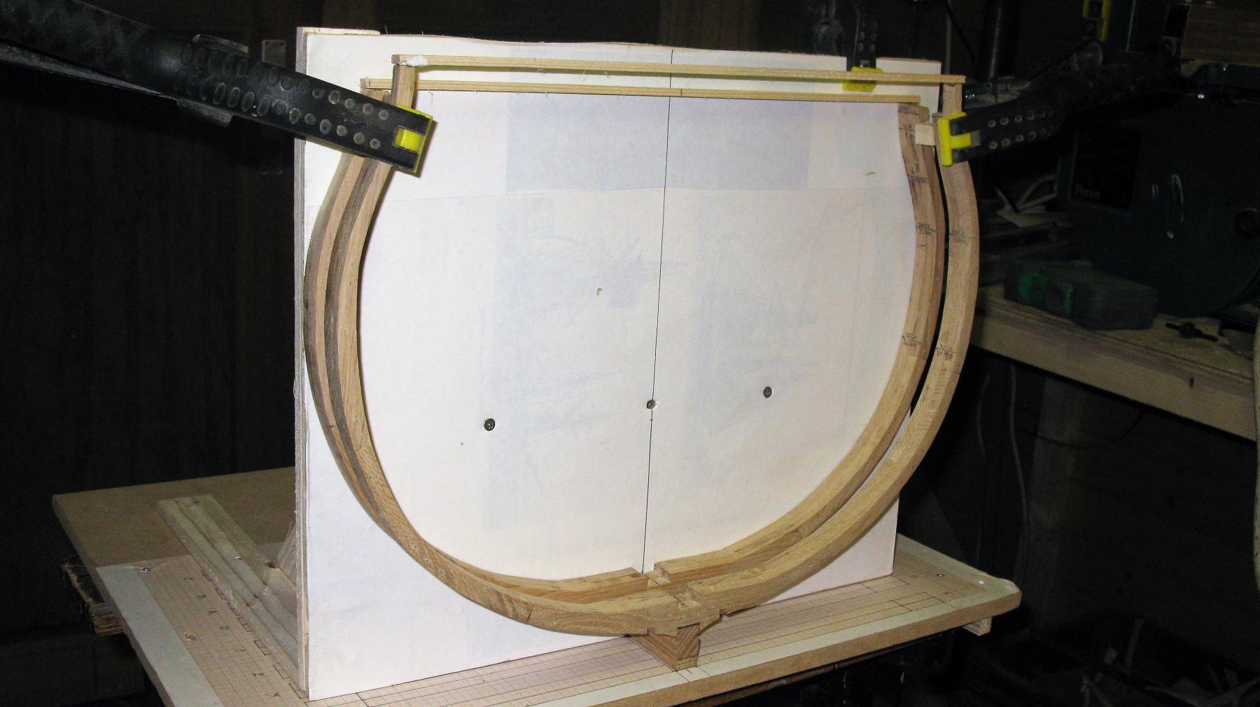
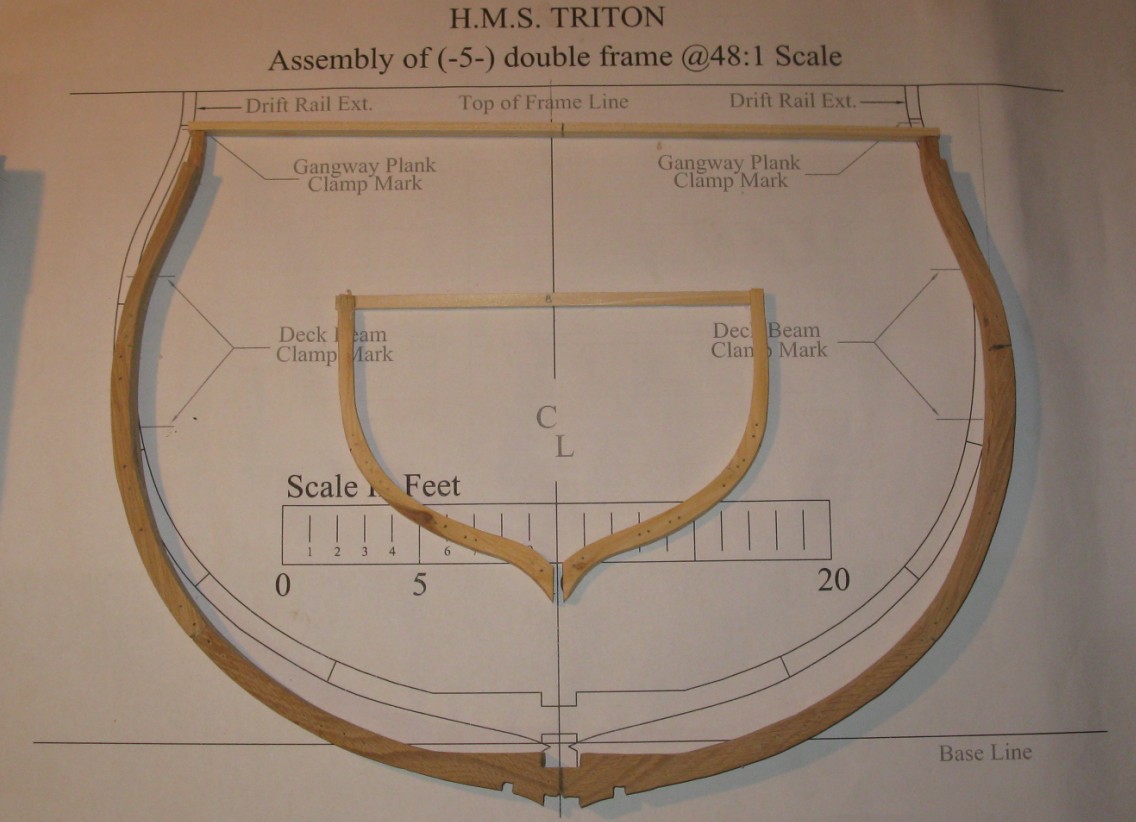
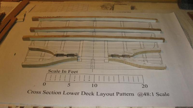
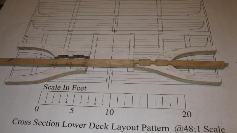
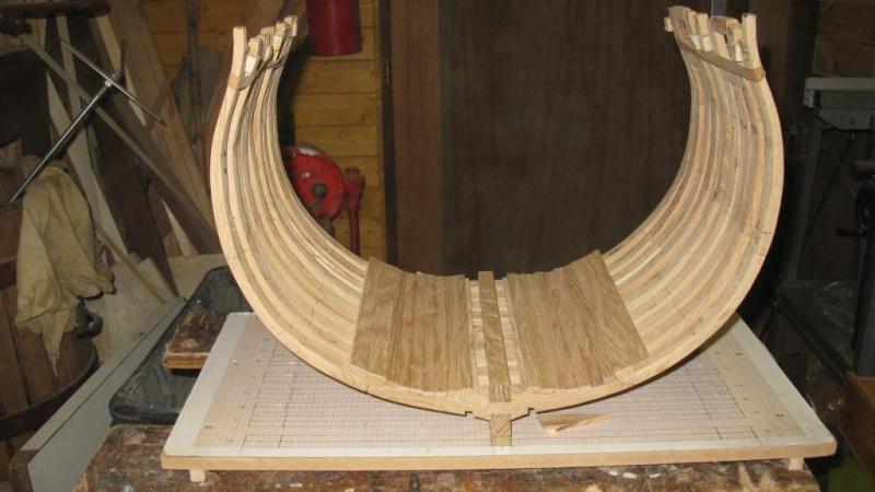
 While the glue is drying I start to make the lower deck beams and the lower deck beam arms. On the fourth picture the deck beams are laid in the model but not yet fastened. Before I will do that, the lower deck has to be tree nailed.
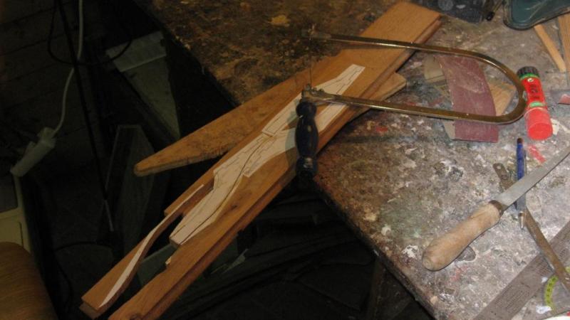
-
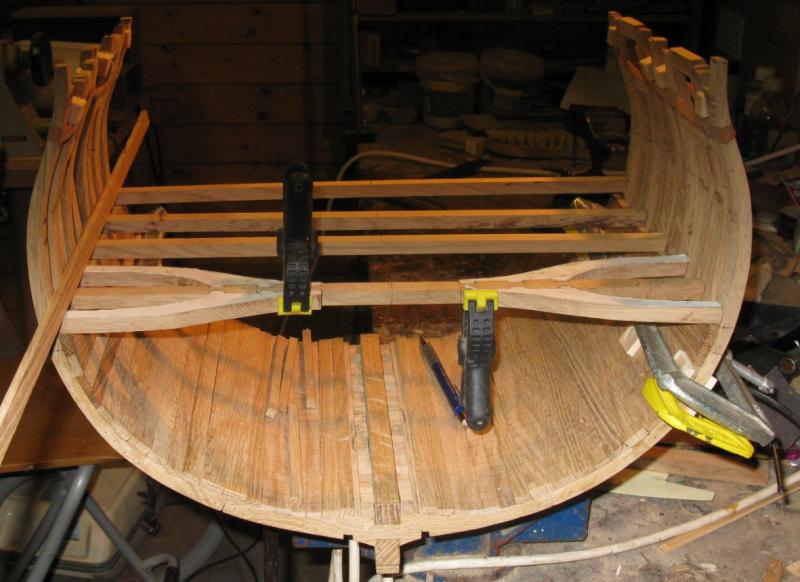
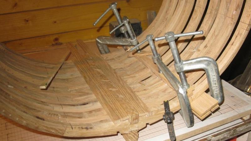
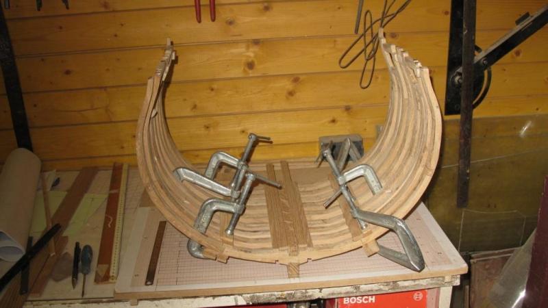
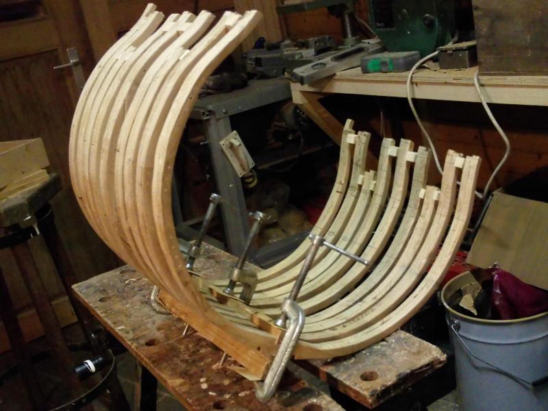
The deck clamps are in place and the last gaps in the planking are filled.

-
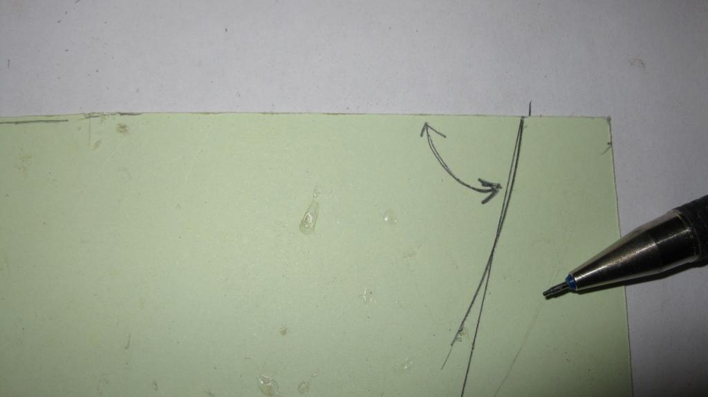
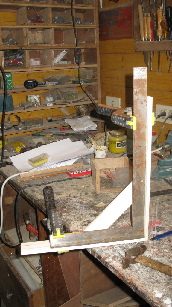
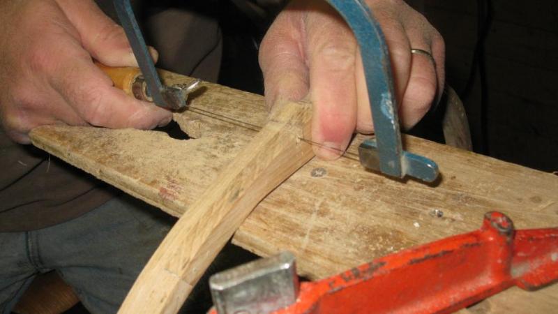
Some special attention is to be drawn to the lower deck clamp. To determine the angle of the upper side of the plank I fasten with clamps a lath on the bottom level of the lower deck beam. I hold a piece of cardboard against the frame and mark the lined of the bottom deck beam and the frame. This cardboard will be the template to saw the deck beam.


-
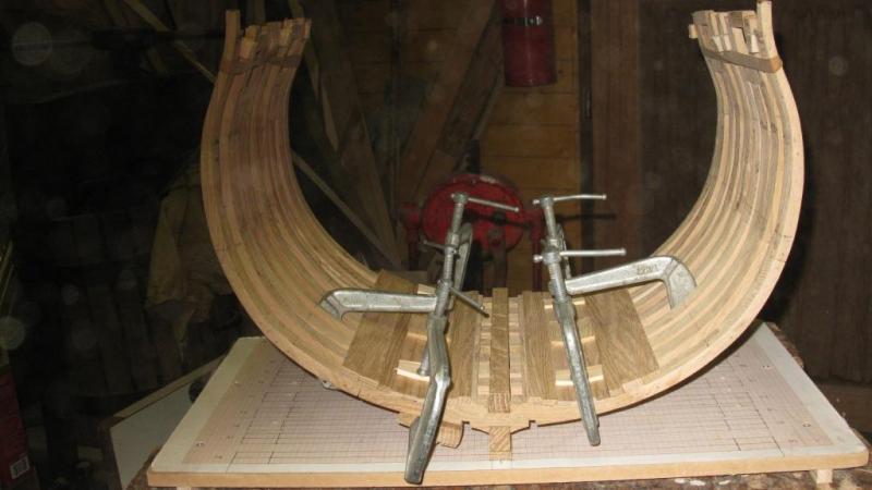
Next thing to do is fixing the inner planking of the lower deck.
-
Pete and Mark, Thank you very much for this useful information. Geert
-
Thank you Mark, I have a question about the limber boards. I guess they were removable to check the level of the water in the bilges. I suppose they were shorter than the lenght of the cross section and there were (finger)holes in it in order to make it easier to lift them up. Do you have an idea of the lenght and the look (from above) of the limber boards? Geert
-
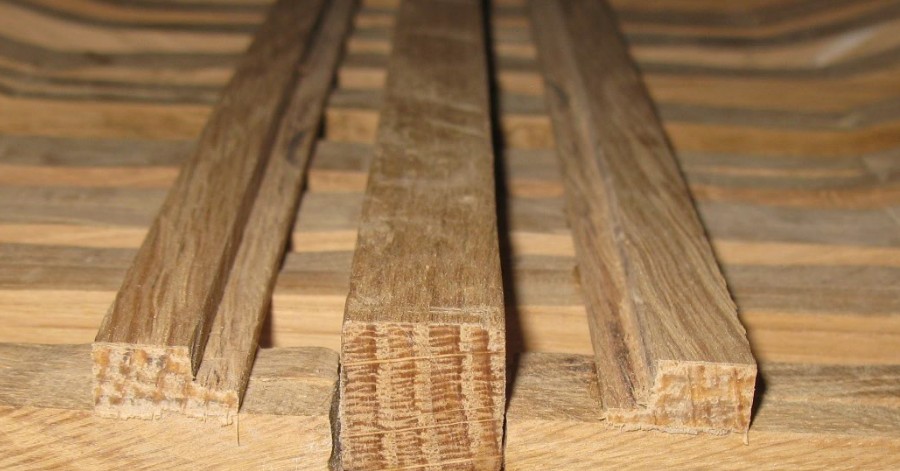
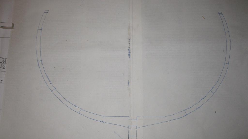
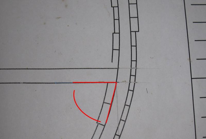
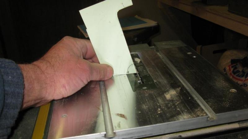
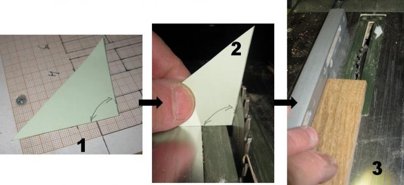
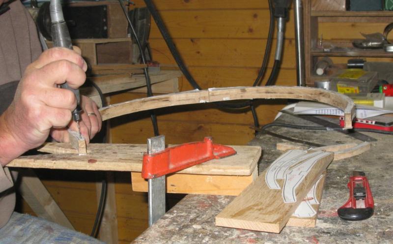
With the template I make a pattern of the angle to set up the angle of the Proxxon saw to saw the boards.
-
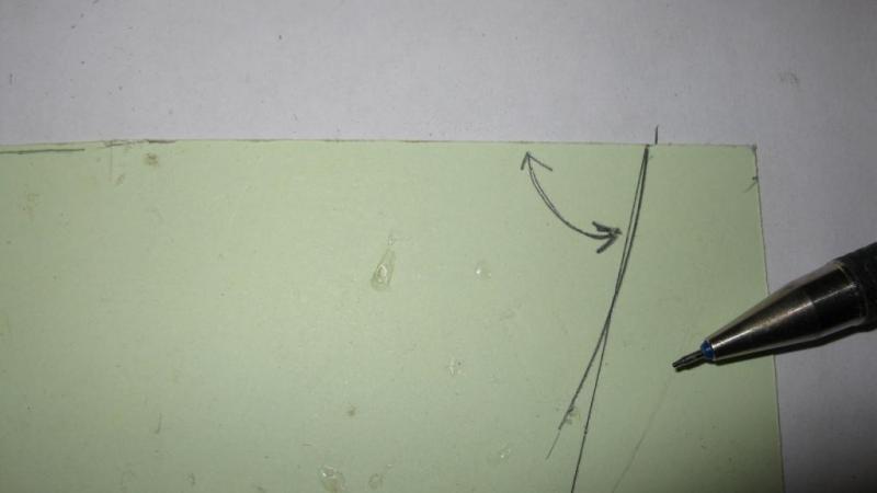
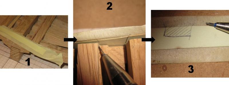
To determine the angle of the sides of the limber boards, I fix a piece of cardboard with some scotch tape on the end of the keelson and limber strake. This way it is easy to line the contours of the space between them. The result is a template of the limber board.
-
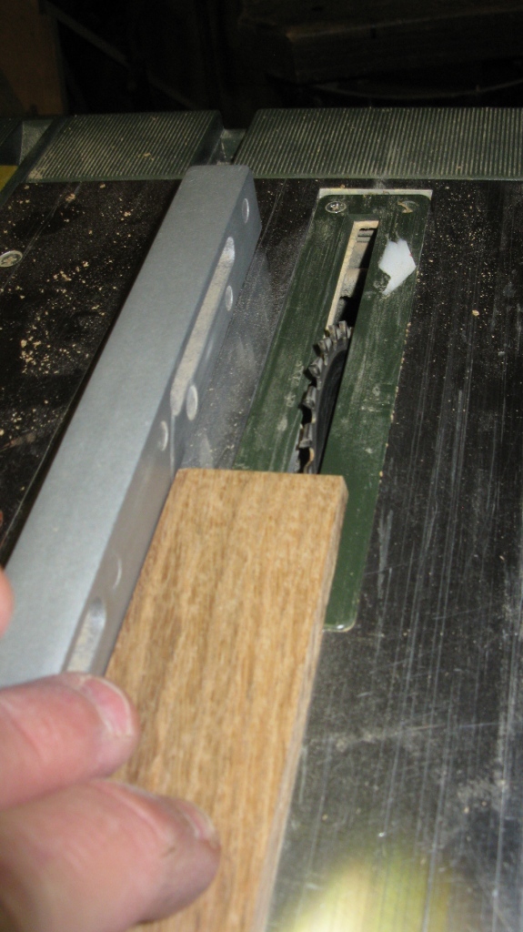
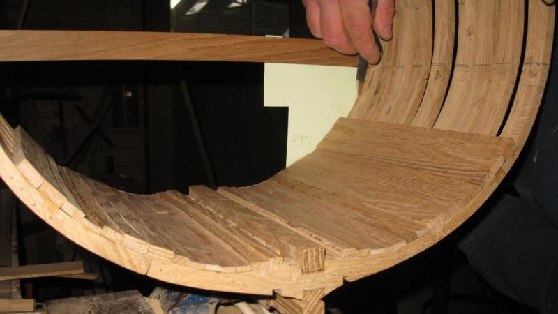
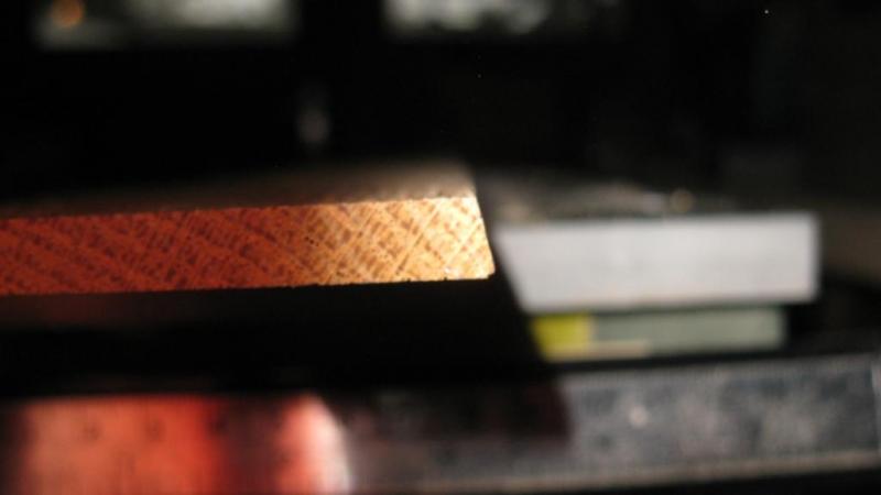
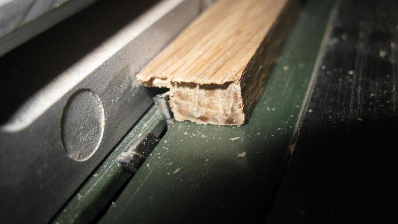
The grove in the limber strakes is made with the Proxxon saw

-
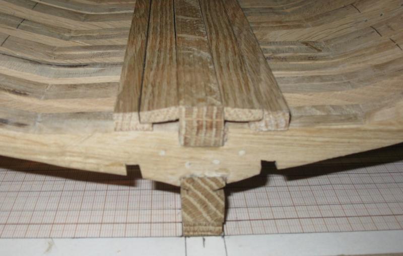
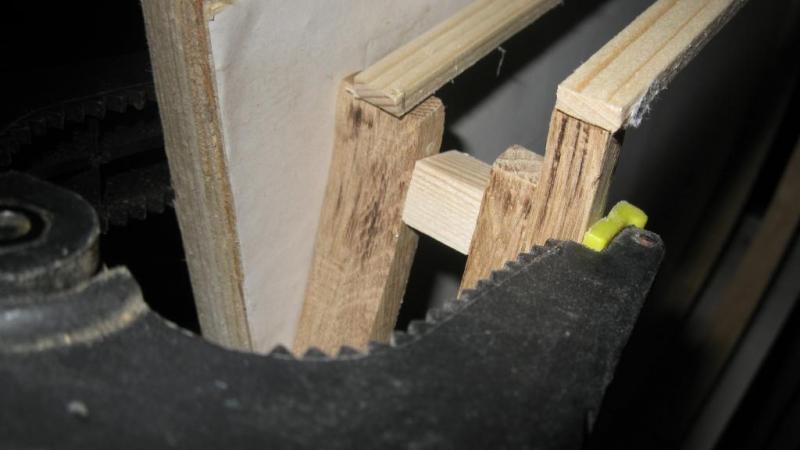
After the sanding I make the notches for the gun port lintels. As can be seen on the picture the frames on the port side are a bit to short below the gun port. Fortunately there will be planking on top of it.

-
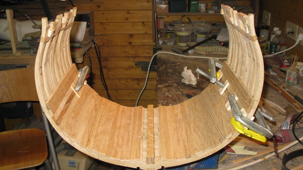
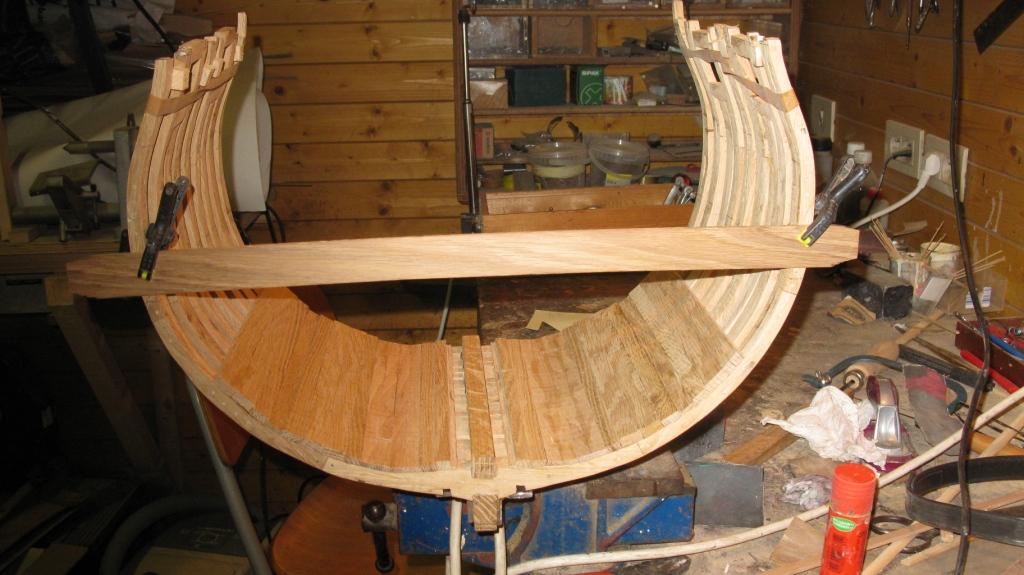
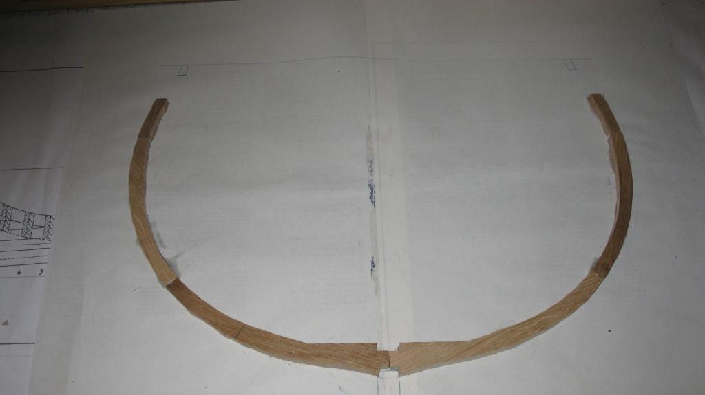
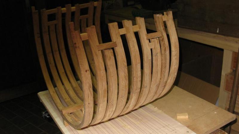
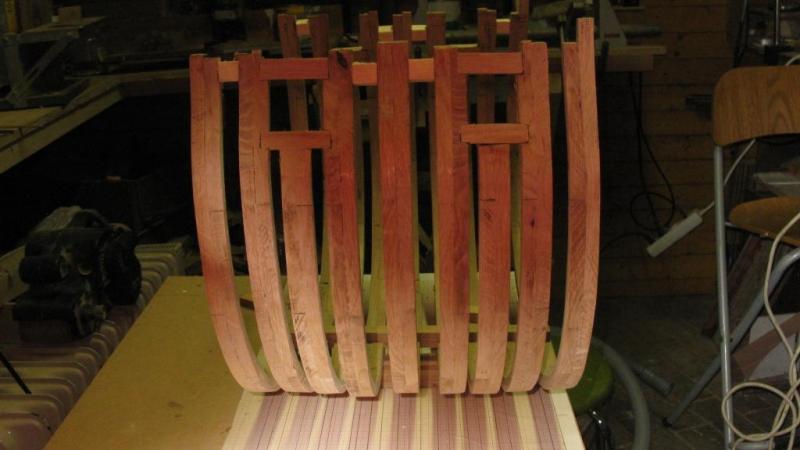
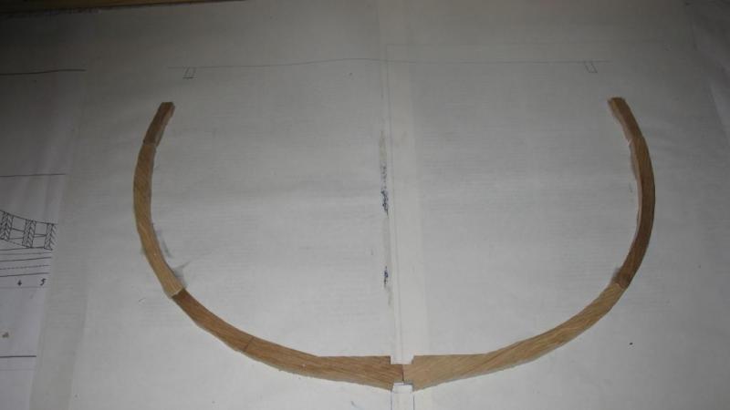
When all the frames are in place, It is time for a first sanding session. Thanks to the large scale, I can use normal tools. After sanding I install the keelson.

-
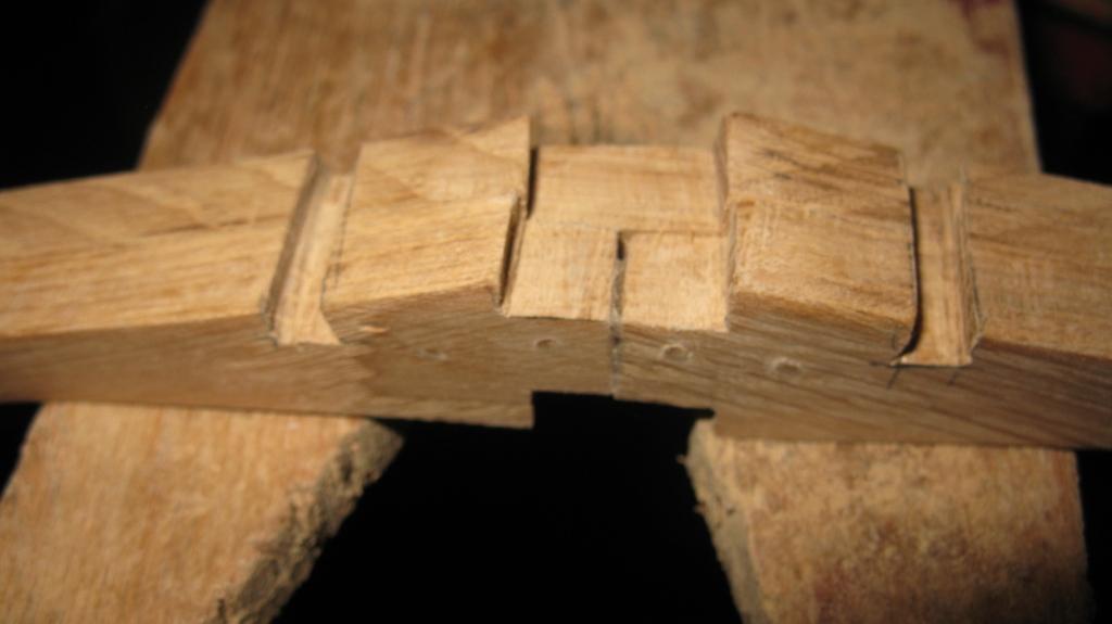
Between the frames, a small piece of wood is glued temporally to keep the correct distance from bottom to top.
-
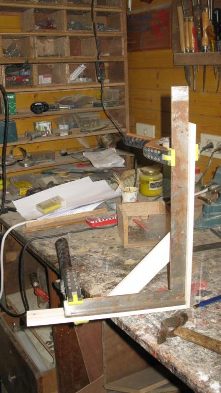
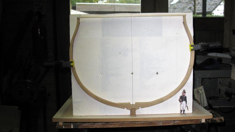
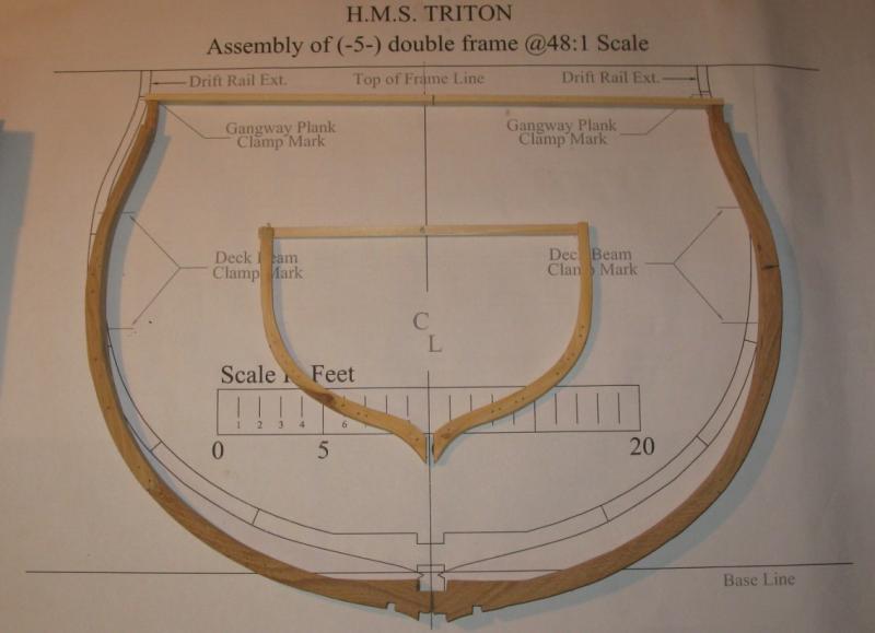
I wish all forum members a happy and prosperous New Year with a lot of modelling pleasure in 2017! Before going to the family this afternoon, I have some time to line up with the progress on the cross section. As an aid to place the frames vertical, I made two wooden perpendicular supports which keep a shelf vertical. On the shelf the middle line of the cross section is drawn. That will be my aid to glue the frames on the keel. The lieutenant on the second picture is in scale 1,70 m high, just to have an idea of the proportions

-
On the plans, no limber holes are marked. I although think that they existed, so I make them, hoping that they are correct.

-
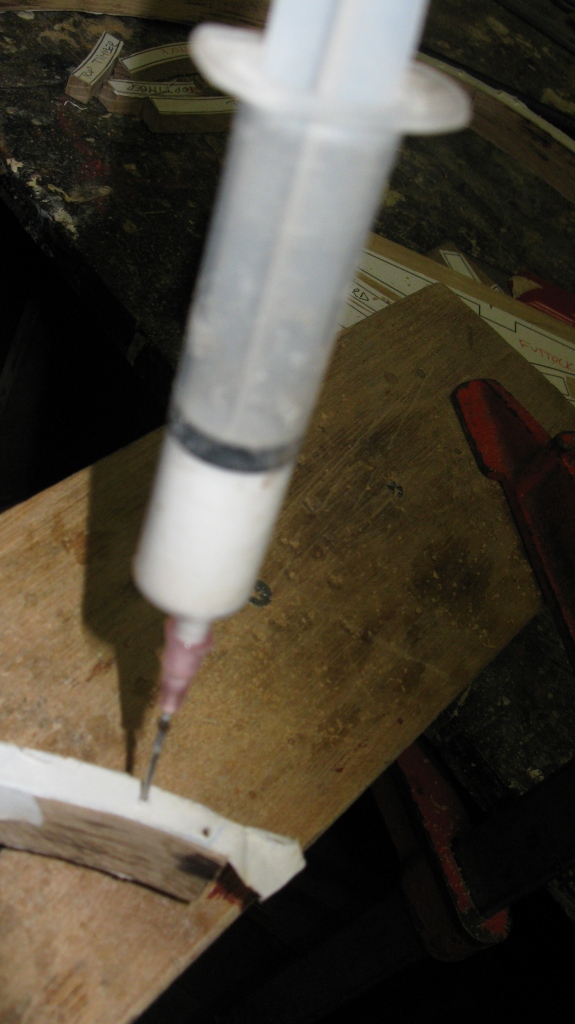
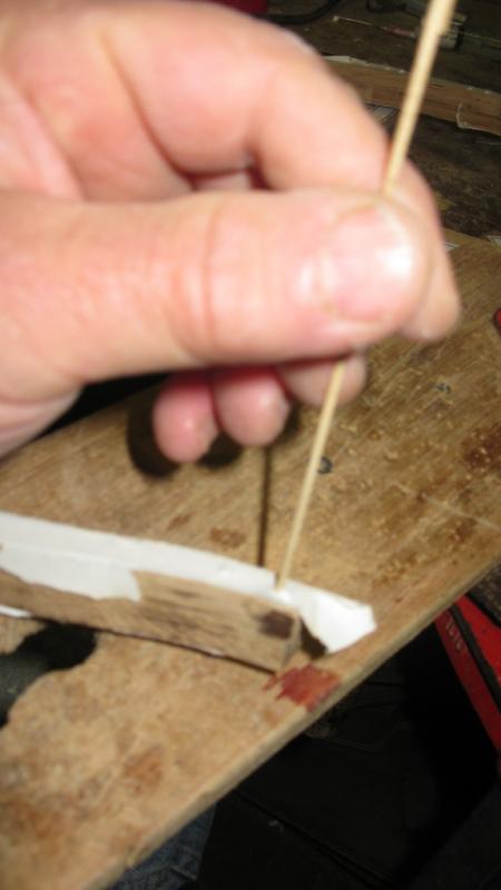
After sanding, I drill holes for the treenails. Some wood glue in it (goes easy with syringe) and then the bamboo nail.

-
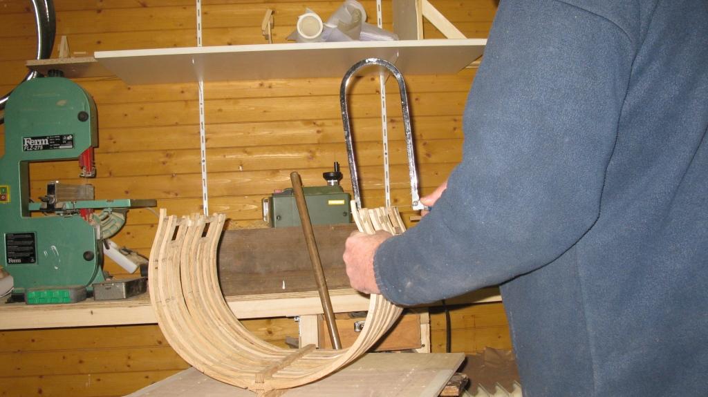
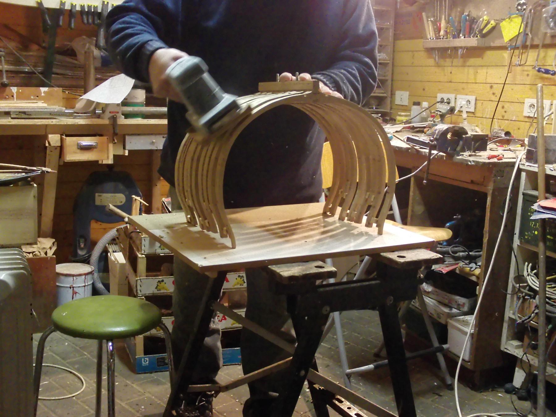
Next day the frame is ready for further treatment: Sanding with the drum sander. You see the result on the second picture. Holding the frame in hands, I am bit surprised of the size of a 1/24 scale frame. Compared with a frame of another project, a 1/20 scale shrimper, it looks enormous.
-
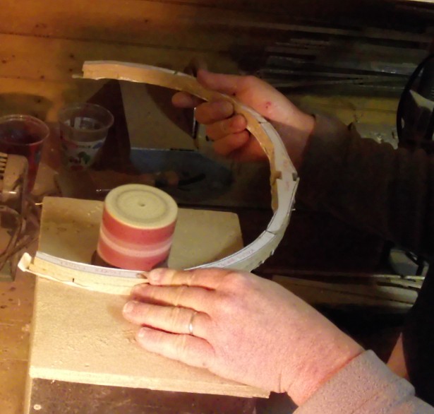
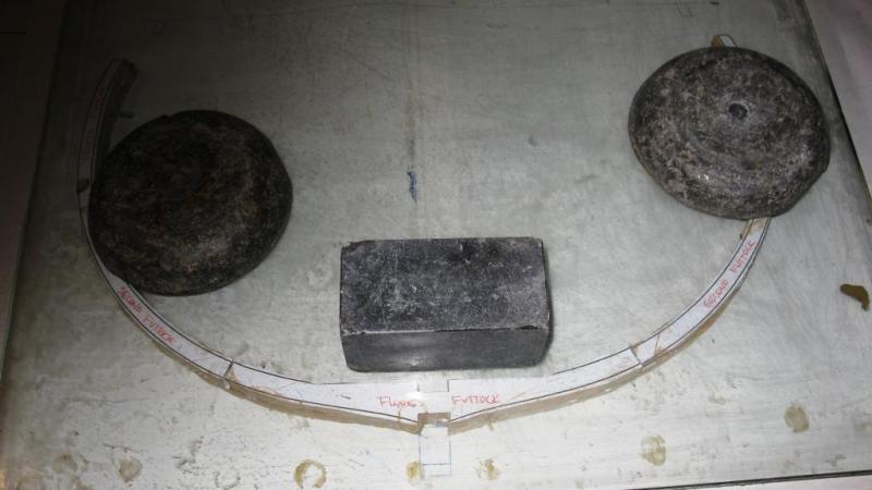
On top of the frame comes a second plate of glass and some lead weights. The glue can dry now.
-
The second layer is glued on the first one with wood glue.
-
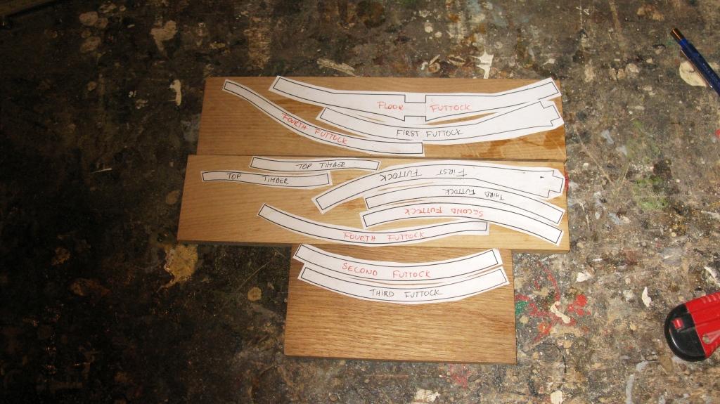
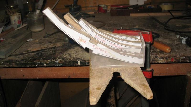
I do not want to spoil my 200% copies, therefore I copy the frame drawing, using carbon paper. I lay the drawing on a plate of glass to have flat surface to assemble the frame. The first layer of futtocks is glued on the drawing with rubber cement. Between the joints of wood pieces I put wood glue.
-
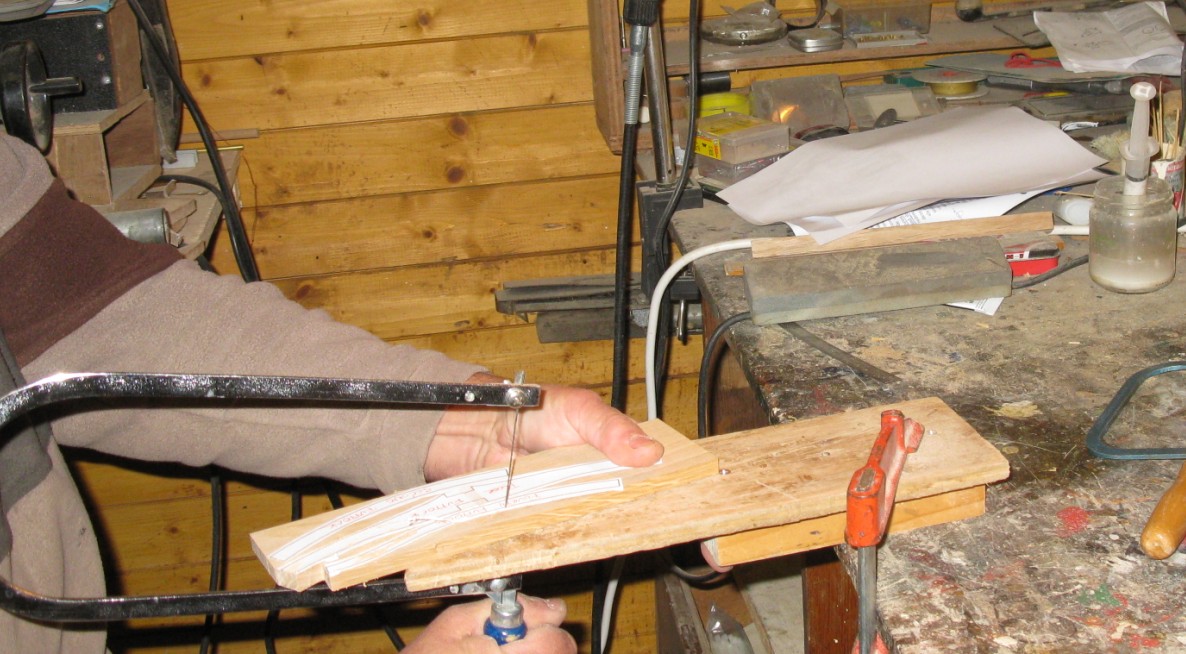
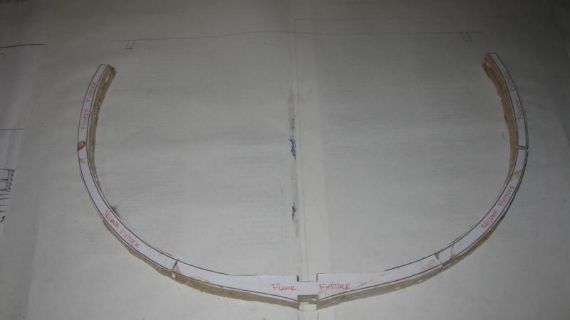
I saw them out with the fret saw a little bit outside the lines.

-
Time to start with the frames. That's a whole frame ready to be saw.

-
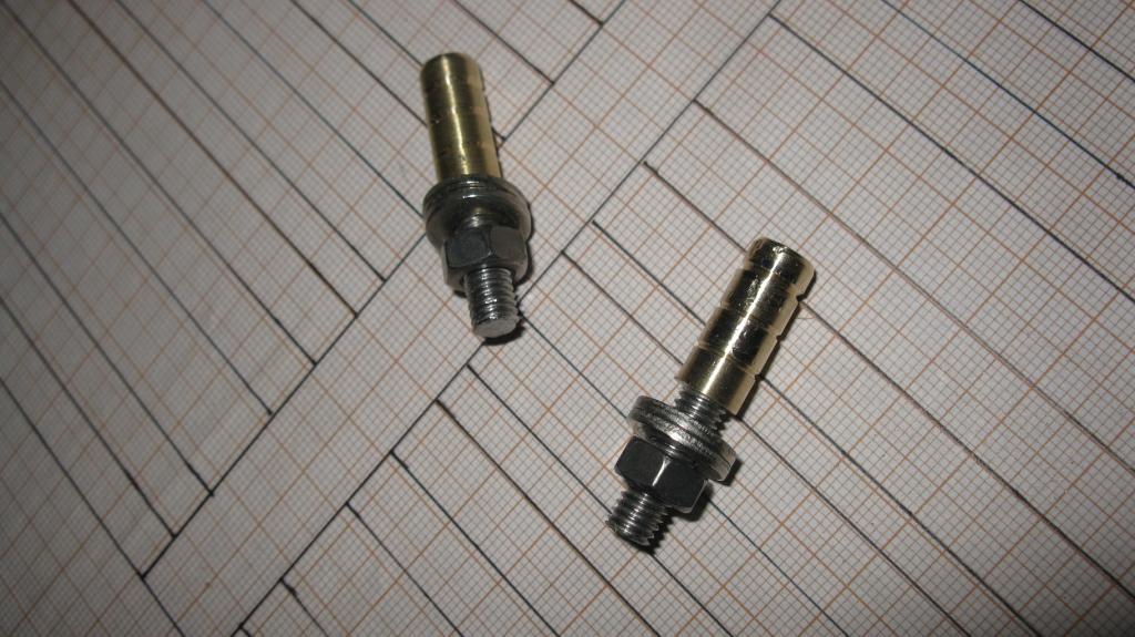
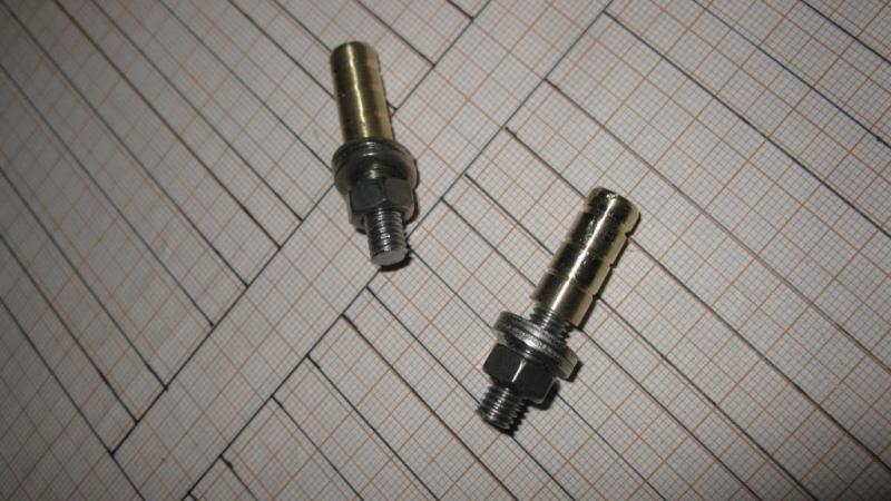
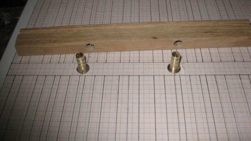
I glue the false keel on the keel. A friend made two brass tubes with screw thread to mount the model. The tubes are bolted on the building plate an two holes with a slight larger diameter then the tubes are drilled in the keel. The keel is pushed on the tubes with some glue in the holes.
-
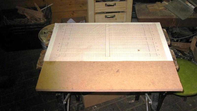
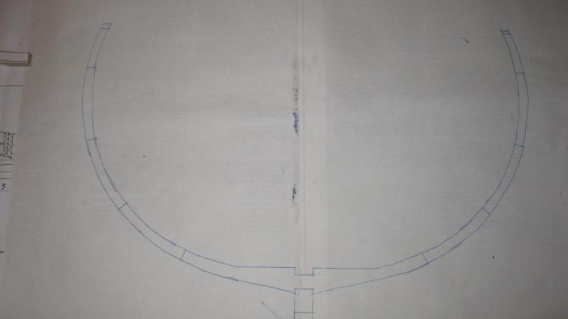
I start my project with making a ground plan of the cross section and gluing that plan on a piece of MDF sheet.