HOLIDAY DONATION DRIVE - SUPPORT MSW - DO YOUR PART TO KEEP THIS GREAT FORUM GOING! (Only 20 donations so far - C'mon guys!)
×


G.L.
-
Posts
1,553 -
Joined
-
Last visited
Content Type
Profiles
Forums
Gallery
Events
Everything posted by G.L.
-
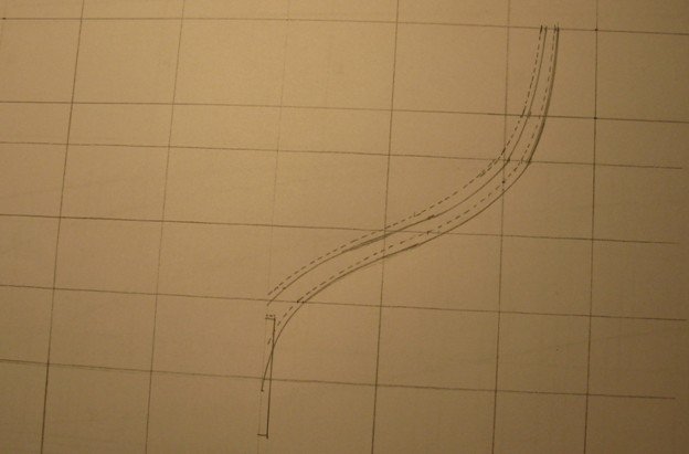
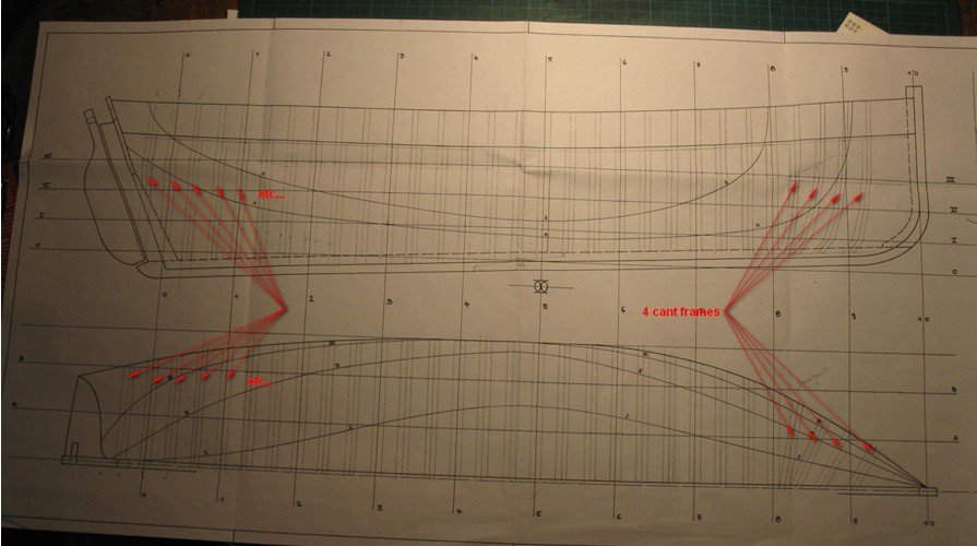
 2.14 The 4 cant frames are drawn in this way. Next things to draw are the keel, the stem and the stern.
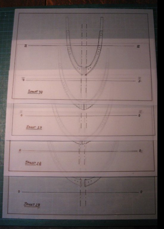
-
2.13 The final copy looks like:
-
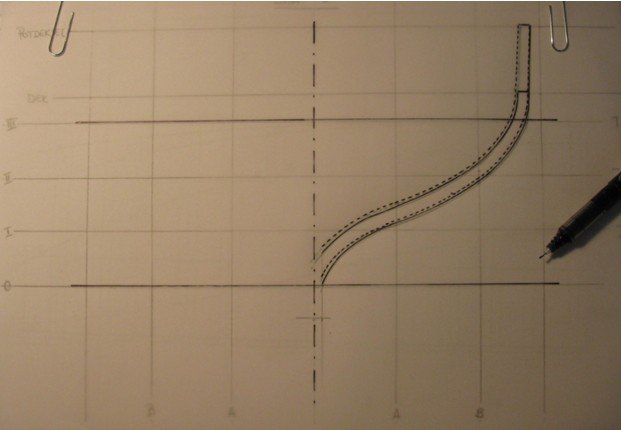
2.12 Once all transferred intersections on the grid are connected, the shape of the cant frame appears.
-
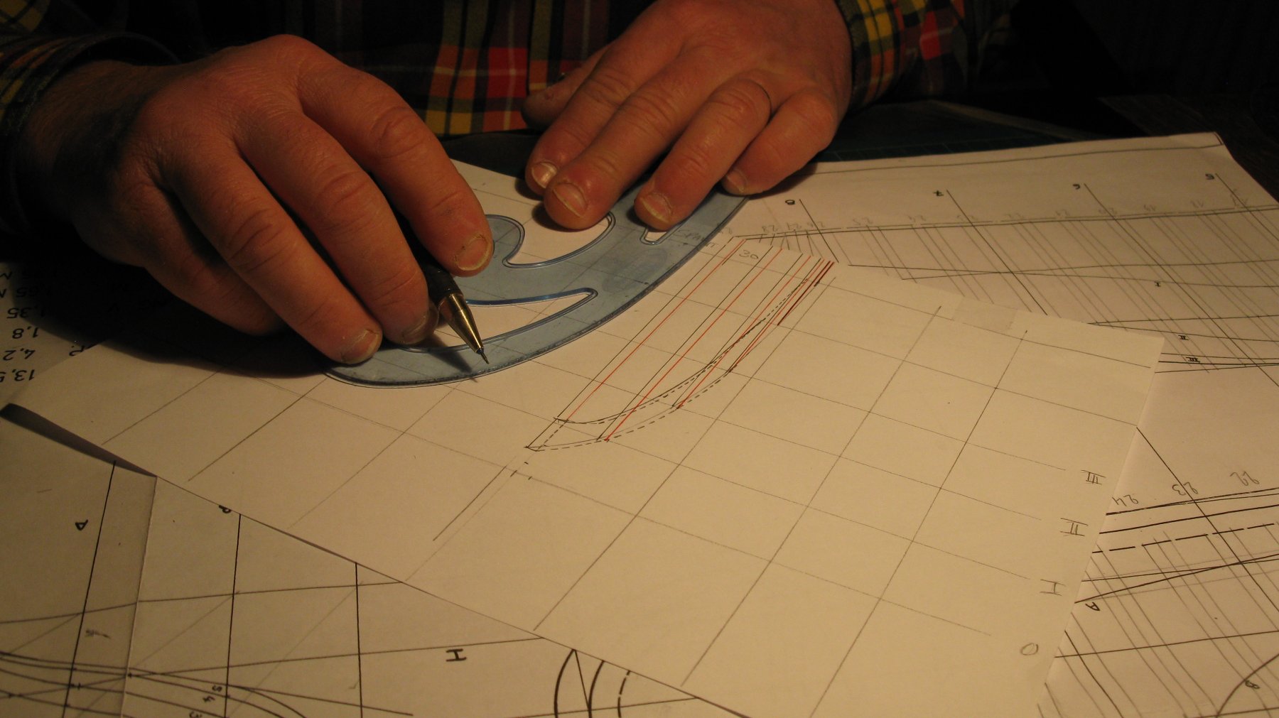
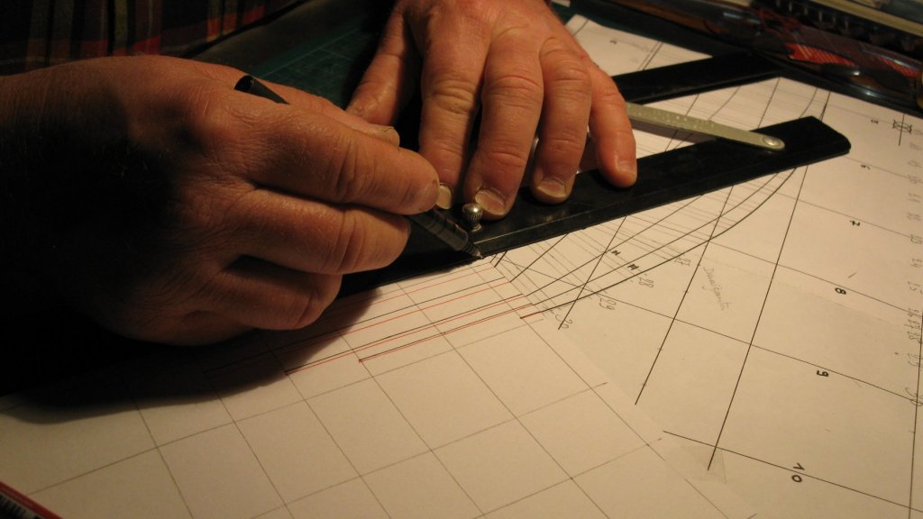
2.11 Afterwards I transfer the intersections of the frame with the different waterlines in parallel with the centerline of the grid to the waterlines on the grid. The black lines are the intersections of the back of the frame, the red lines the front.
-
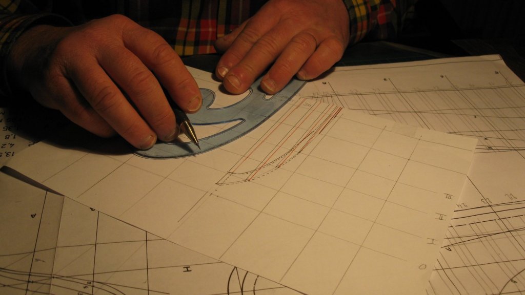
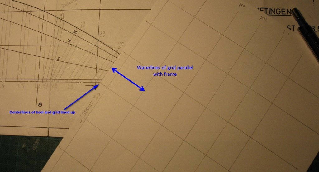
2.10 All the square frames are drawn. For the cant frames another technique is to be used. I place the grid with its centerline touching the centerline of the keel on the fore end of the frame and the waterlines on the grid in parallel with the cant frame.
-
2.9 I didn't yet mention the dimensions of the Ostend shrimper: - LOA: ± 13 m - Beam: ± 4 m - Depth: ± 1.8 m - Draft: forward: ±1.3 m amidships: ±1.6 m aft: ±1.9 m

-
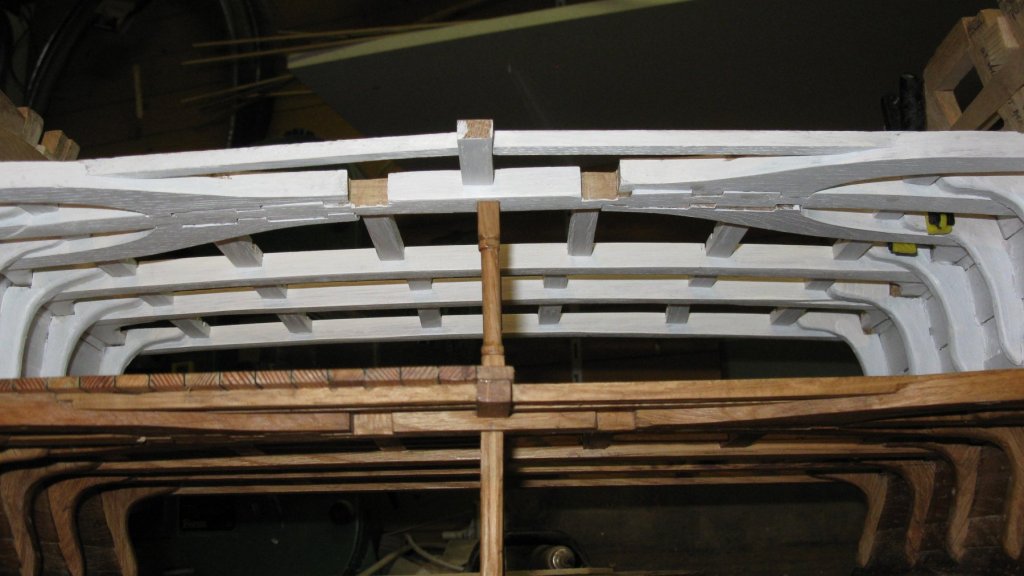
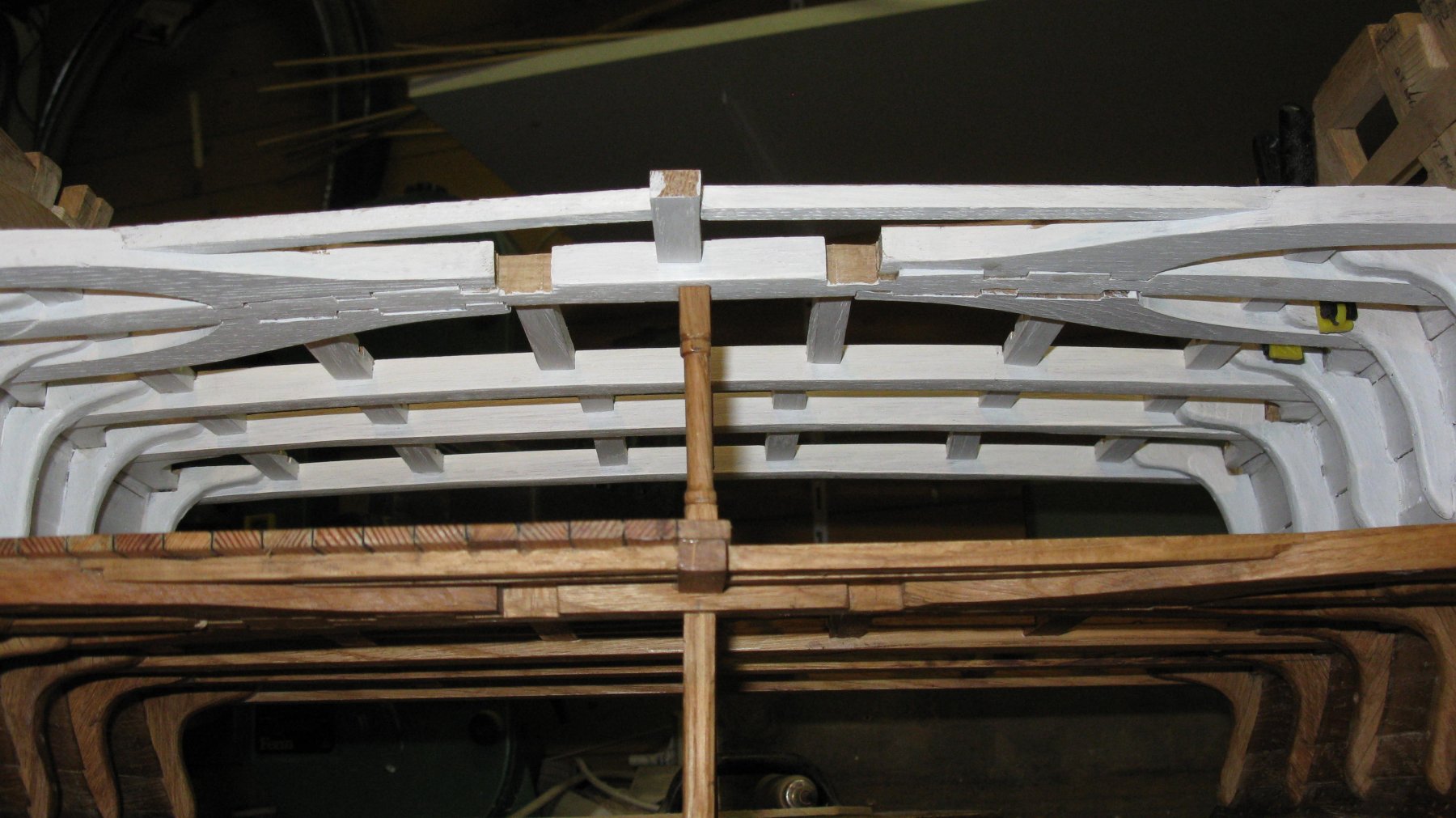
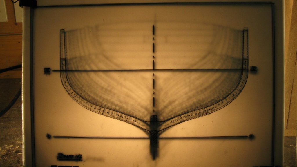
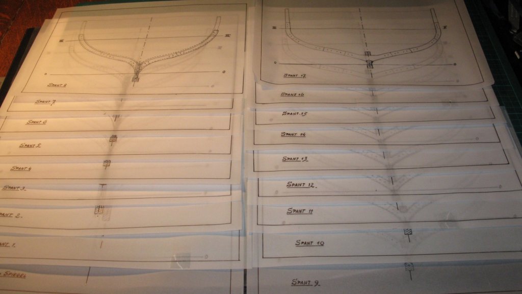
2.8 When I place all the tracing papers one after another between two plates of glass with a strong light behind it, I have already an impression of the interior of the hull.
-
2.7 This has to be repeated for all 30 frames, so I know what to do in the weeks to follow. The back half of the frames is drawn. Now the forward part.
-
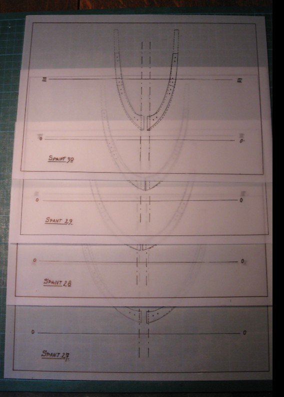
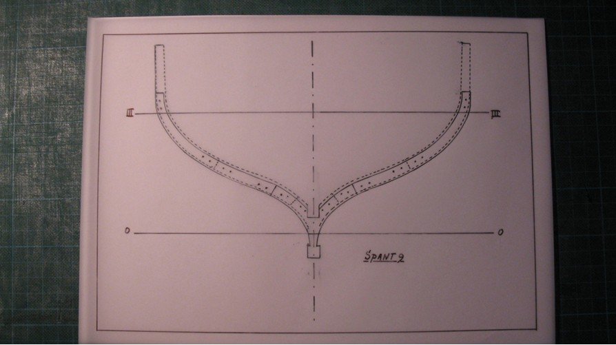
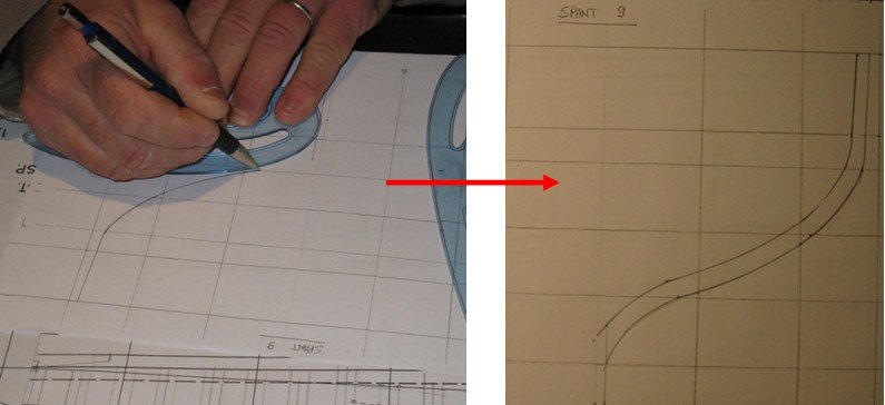
2.6 Then once again with the tracing paper reversed and I have a drawing of a complete frame.
-
2.5 To obtain a full frame. I copy the half frame on tracing paper.
-
Thanks, Patrick
-
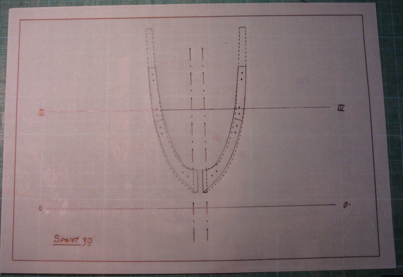
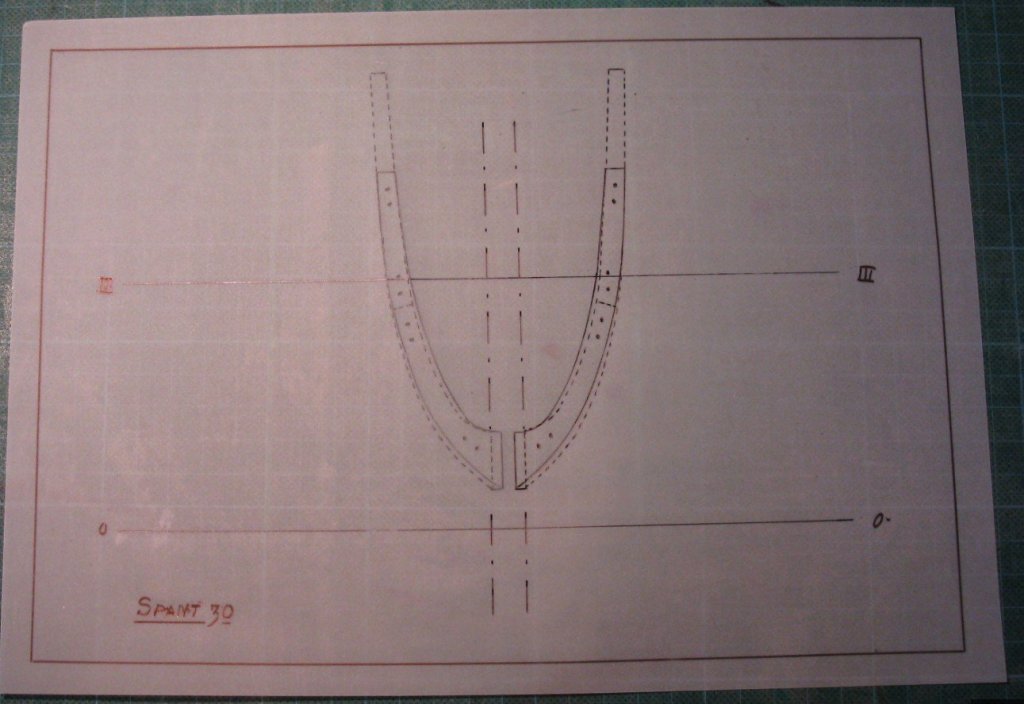
2.4 When I repeat the same procedure with the aft end of each frame, I have also the shapes of the bevel of the frames (dotted line).
-
2.3 Connecting all those measurements with a smooth curved line gives me the shape of the frame.
-
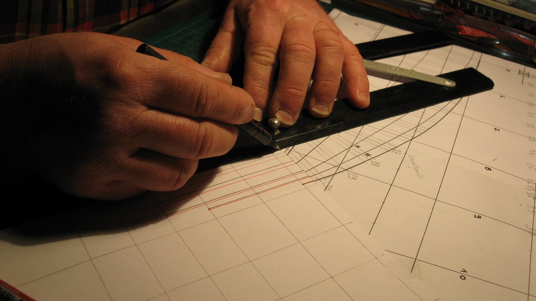
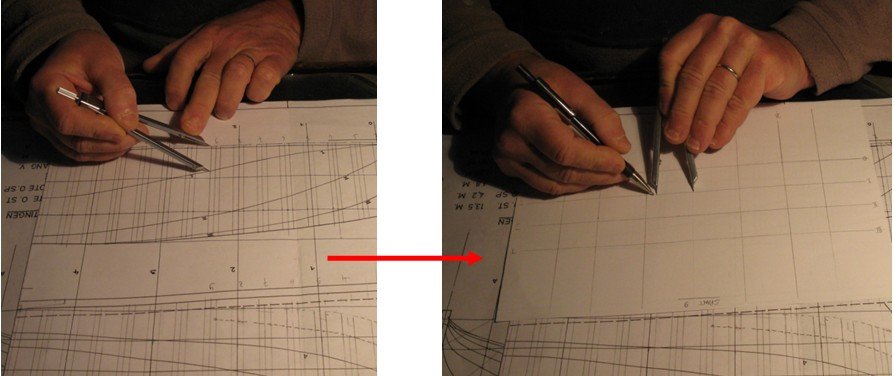
2.2 Next thing to do, is lofting all frames on a grid. Therefore I transfer the measurements of the forward end of each frame on each waterline and each buttock line with a divider to the grid.
-
Part 2: Lofting the frames 2.1 Flemish fishermen were built with frames of two layers oak, each 10 cm thick. The frames were spaced with 40 cm on the centers. So the first thing to do, is drawing the frames on the profile and the half breath plan. The forward 4 frames are cant frames.
-
Jan and John, Thanks for your interest and your kind words. G.L.
-
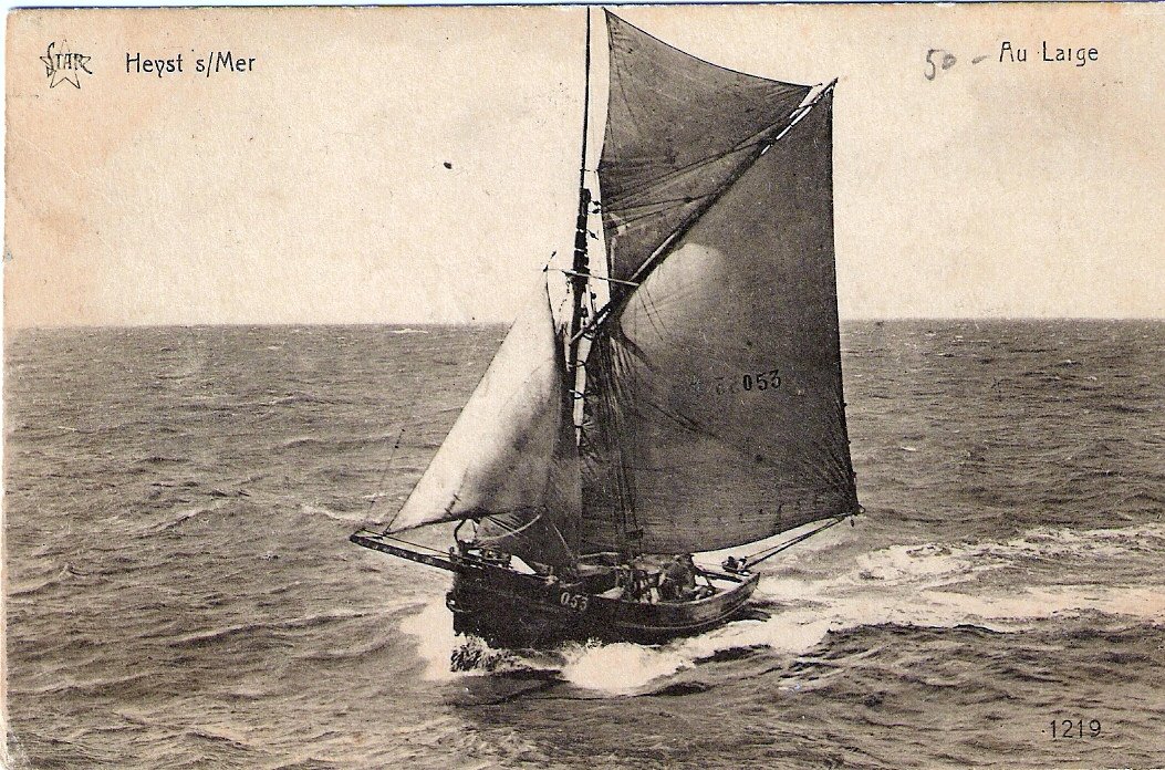
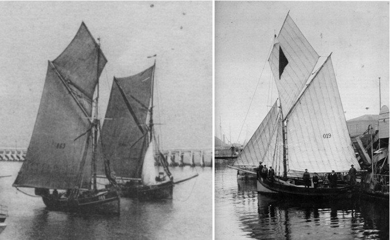
1.2 Restart of the log, originally sep 2015: I visit the forum already during some months and I am amazed by the beautiful masterpieces that you all make and by the skills you all have. I realize that I have a lot to learn before I fit well in your company. But I do not want to take only advantage of your building logs; it is time for me to start a first own project and to share my experiences on the forum. As I am an novice in the world of ship modeling, I want to start with a simple vessel. I will build an 'Oostends schipje'. That is how the fishing sloop is named in Flemish. Literally translated it means 'little ship of Ostend'. I believe that 'Ostend shrimper' is a more convenient translation. The sloop was used from the mid 19th till the mid 20th century to fish grey North Sea shrimps along the Flemish (Belgian) coast. Most of the boats sailed from and were build in the port of Ostend. I bought the plans in the modeling club of which I am member. The drawings are for building a plank on bulkhead (POB) model, giving the shapes of 10 frames. However, I want to build a plank on frame (POF) model, so I will have some additional drawing work to determine the shapes of the remaining frames, 30 in total, the keel and the stems.
-
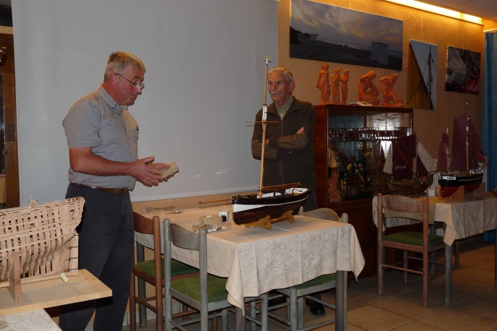
Part 1: Introduction 1.1 A couple of weeks ago I lost the entire building log of my shrimper. The loss is probably caused by a wrong manipulation of myself, I am not quite aware what exactly happened. It is a bit a bore because I started the log already more than 2 years ago and my ship was beginning to gain final shape. Fortunately, I kept a back up of all my posted reports and pictures. In consultation with the forum administrators, I decided to repost all my contributions and rebuild my log to the stage in which my model currently is. My excuses to the people who followed my project, they must have some patience because it might take some time before I arrive again the current state. For the people who did not follow my log, the picture below is showing what my project is about. I presented my unfinished model for the first time in the model discussion of my modeling club (https://dedissel.weebly.com/) last October. I am standing at the left side of the picture, the man to the right is the discussion moderator, a very experienced modeler. This time I intend to divide my log into chapters and to number all my reports. That will make it easier to refer to previous posts.
-
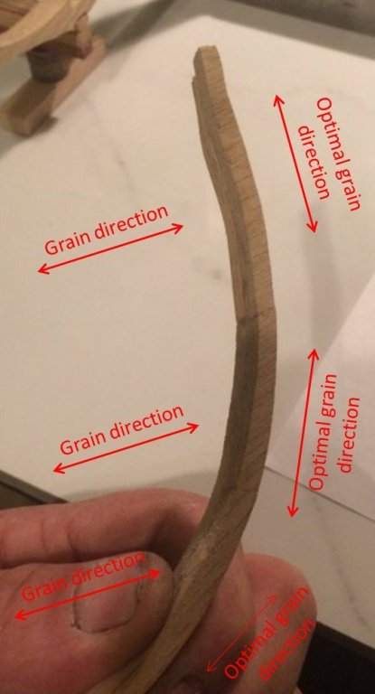
Hey Derek, You are going fast! Your cross section quickly takes shape. Nice repair you made at your frame. I believe that your frames are a bit fragile because the wood grain of the futtocks is at places very transversal. It had maybe been better that the grain follows more the direction of the futtock length. G.L.
-
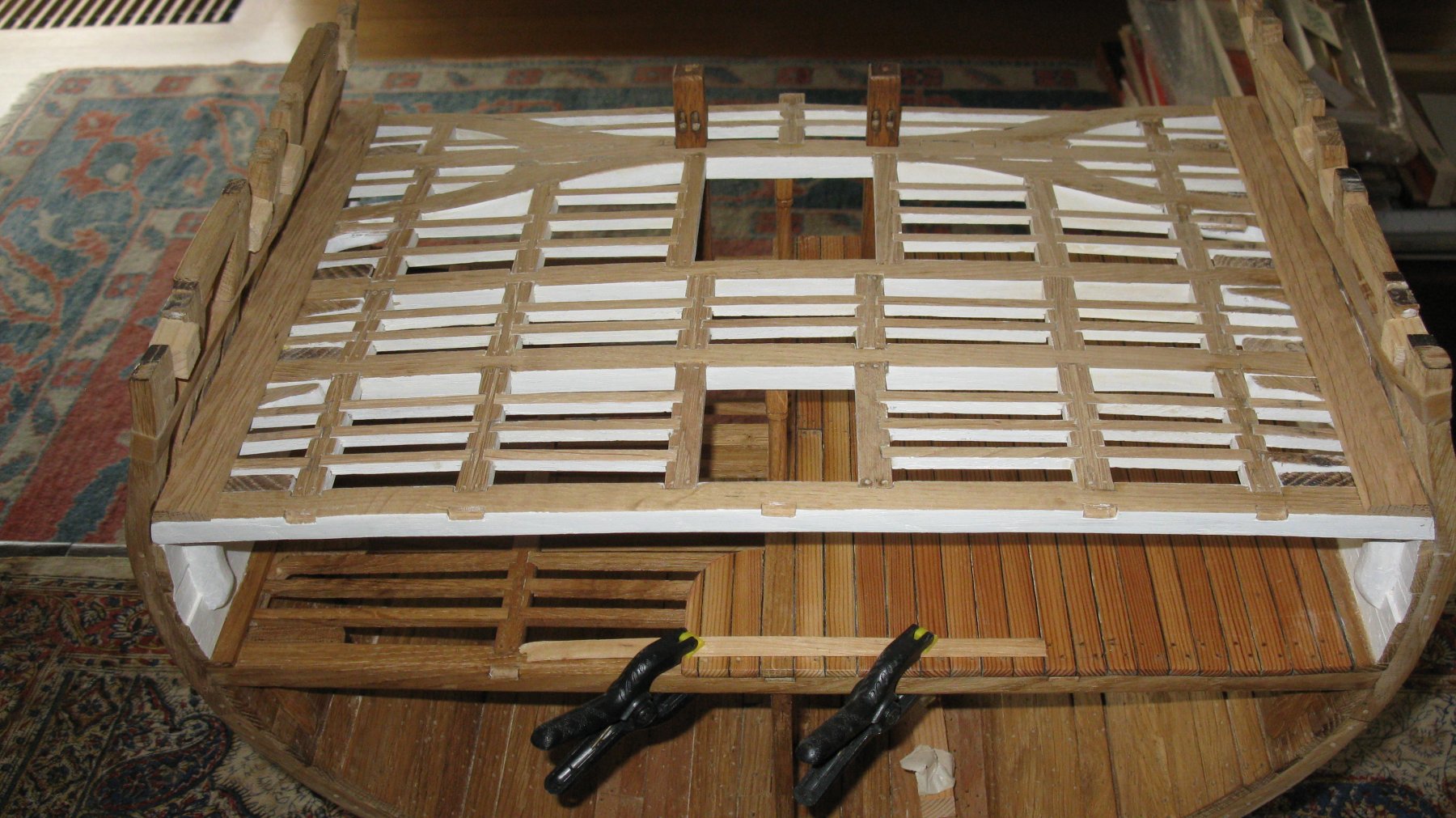
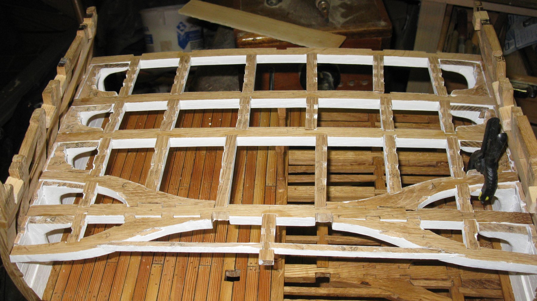
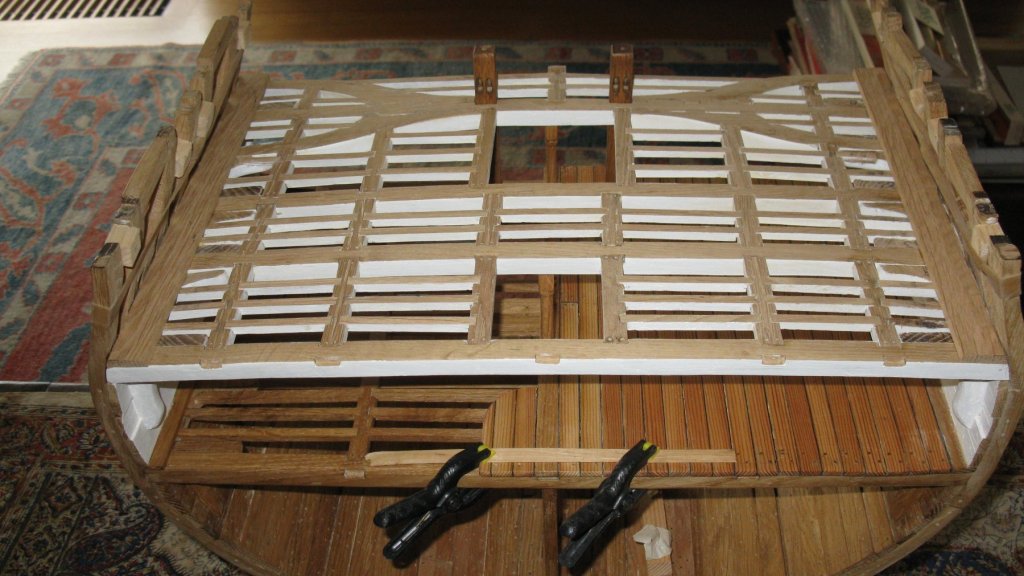
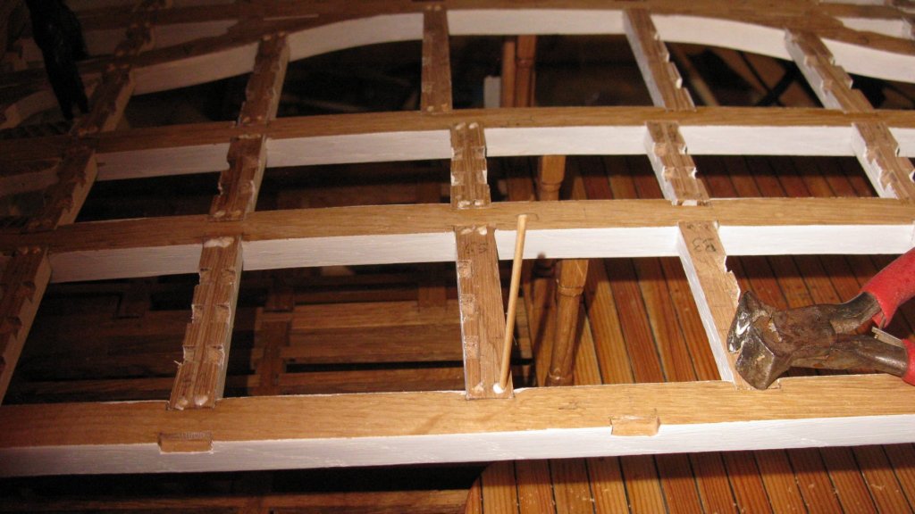
Gun deck structure finished.
-
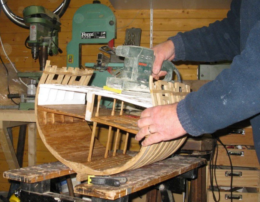
Finally the sanding.
-
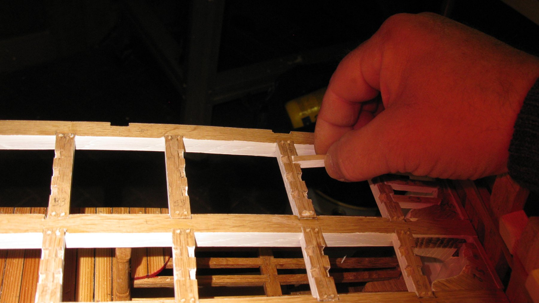
Now the ledges can be glued.

-
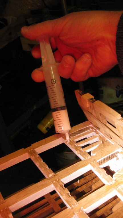
Tree nailing the carlings.
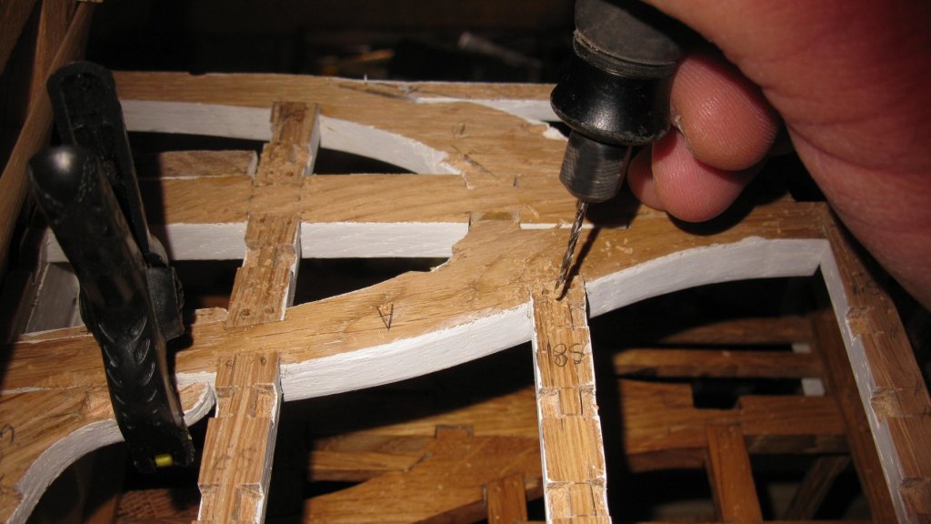
-
When the pinchers can be removed, I place the carlings.