HOLIDAY DONATION DRIVE - SUPPORT MSW - DO YOUR PART TO KEEP THIS GREAT FORUM GOING! (Only 68 donations so far out of 49,000 members - Can we at least get 100? C'mon guys!)
×


hdrinker
-
Posts
232 -
Joined
-
Last visited
Content Type
Profiles
Forums
Gallery
Events
Everything posted by hdrinker
-
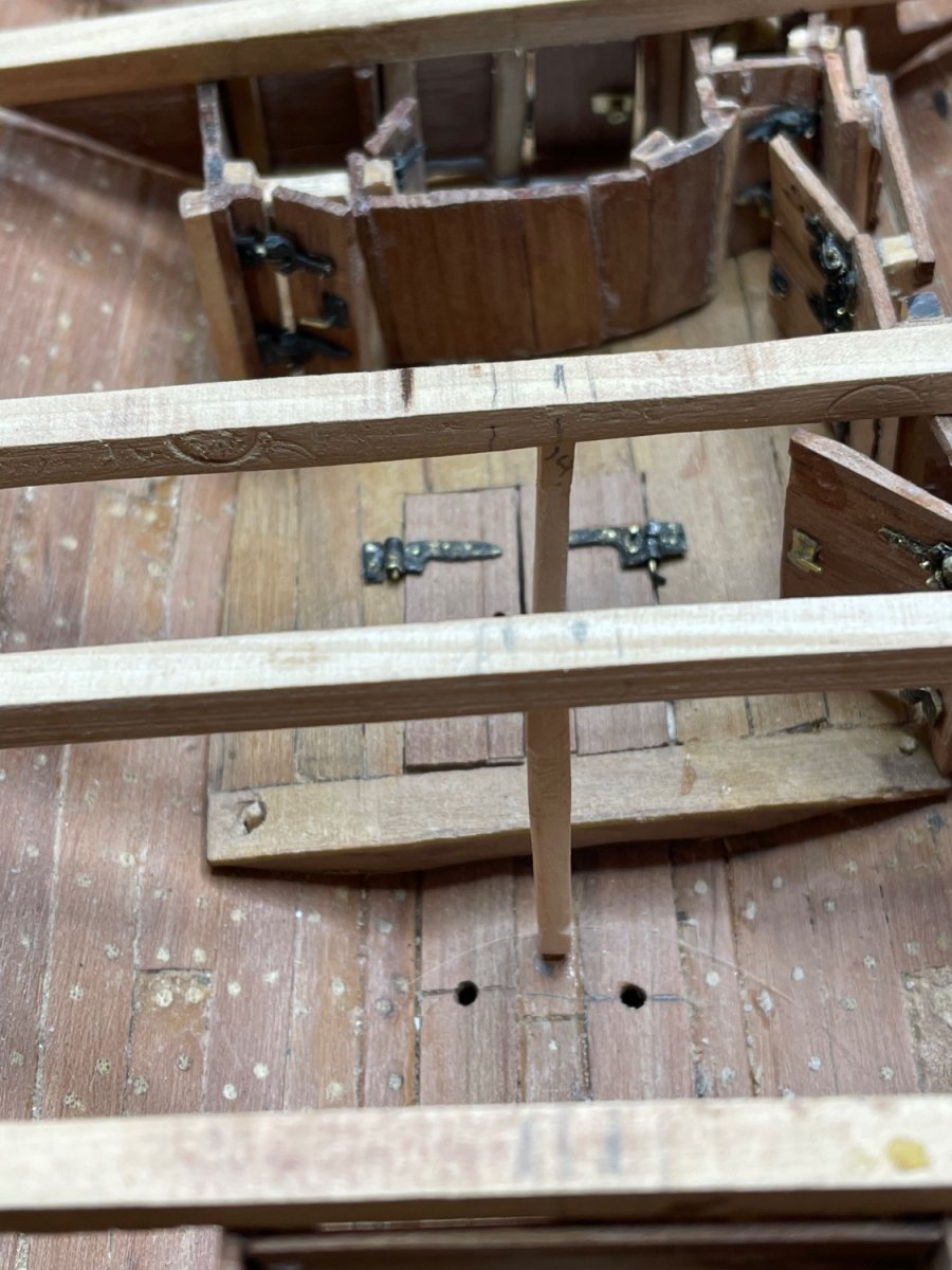
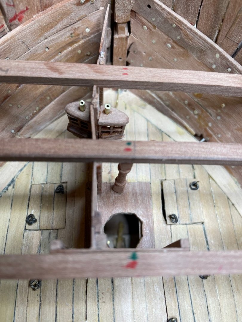
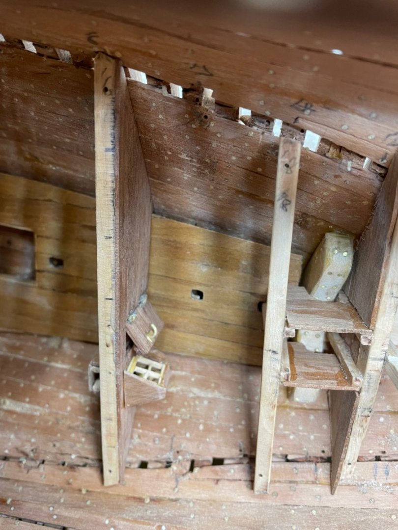
Starting the forward cabins. The lights shown here are truly a challenge. Just when I think I’ve got it all together, except for the last little piece, it all falls apart! But they’re better than the magazine light, so I guess I’m progressing. Henry
- 257 replies
-
- 8
-

-
- pegasus
- Swan-class
- (and 1 more)
-
Thanks, John. I’ve used colored PVS but like Kevin Kenny’s pencil method more. Henry
- 257 replies
-
- 2
-
-
- pegasus
- Swan-class
- (and 1 more)
-
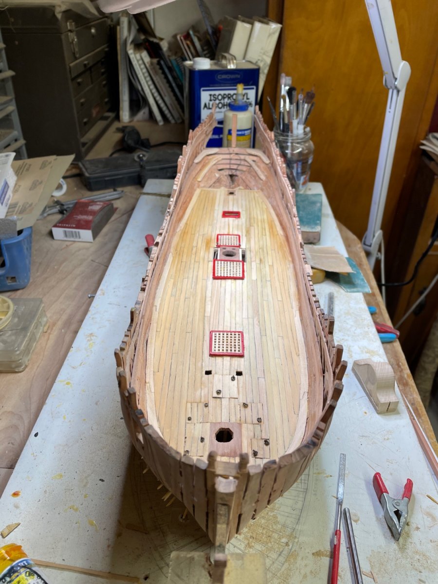
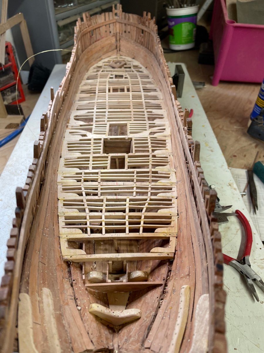
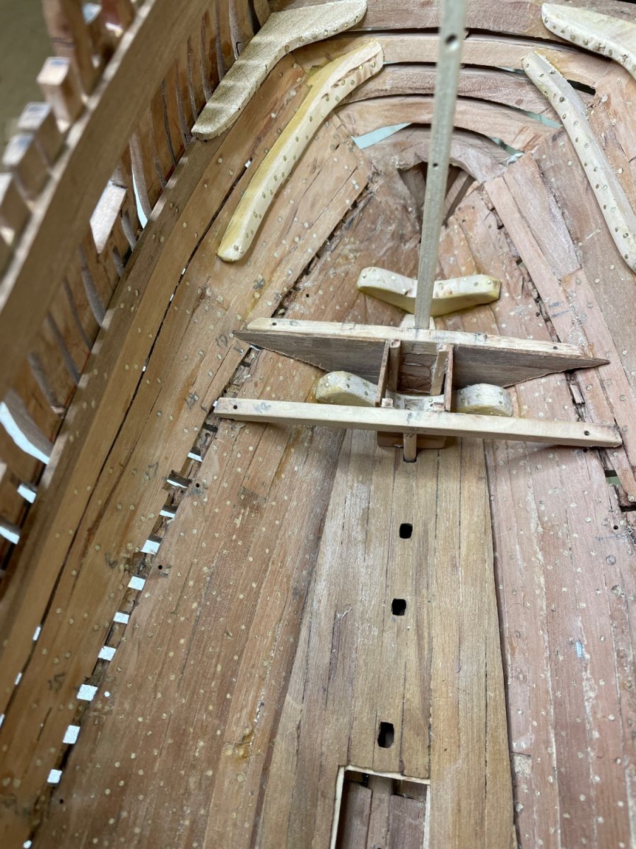
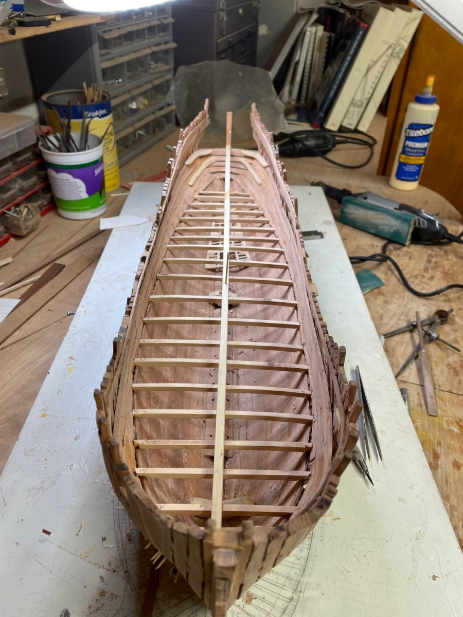
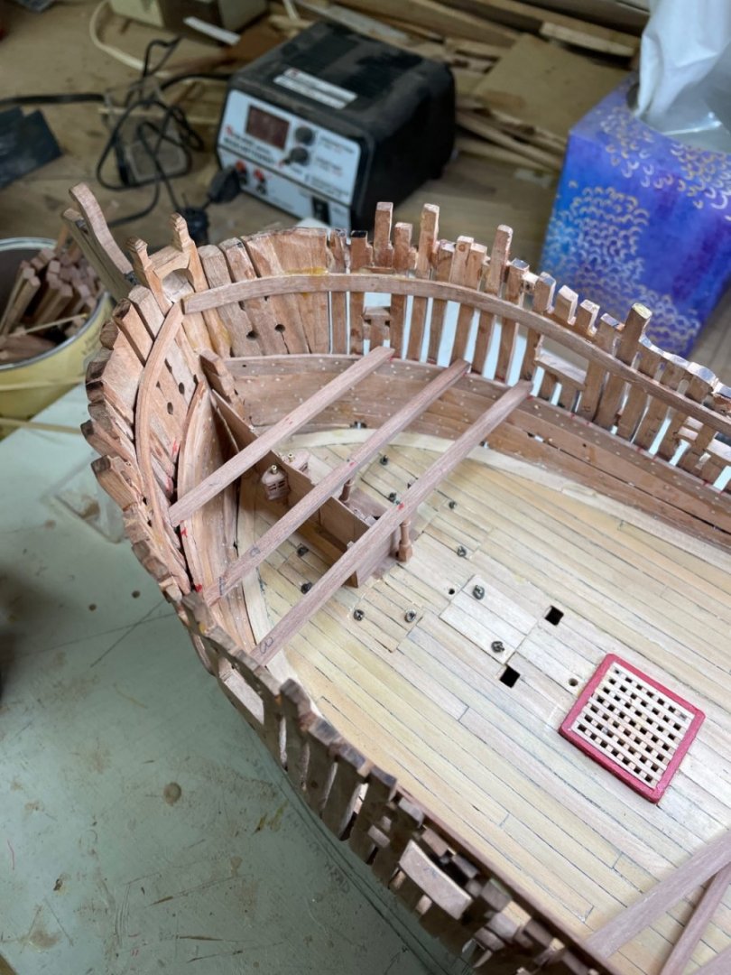
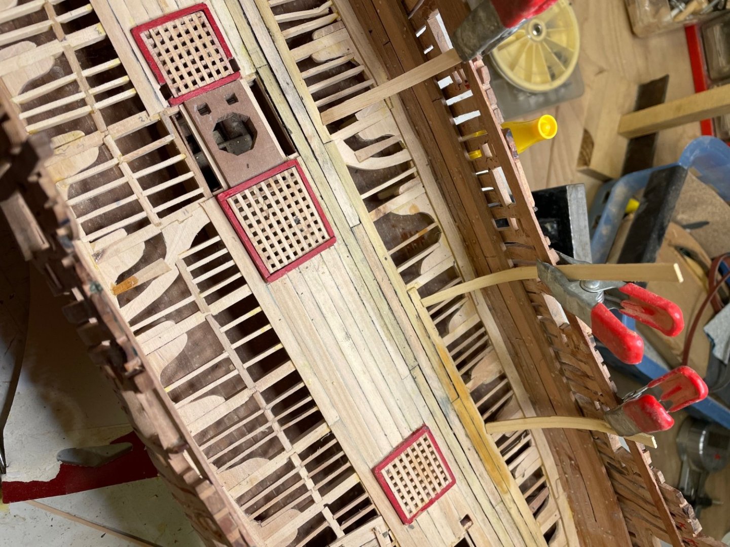
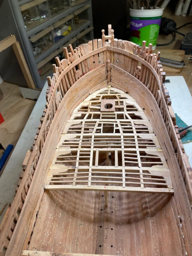
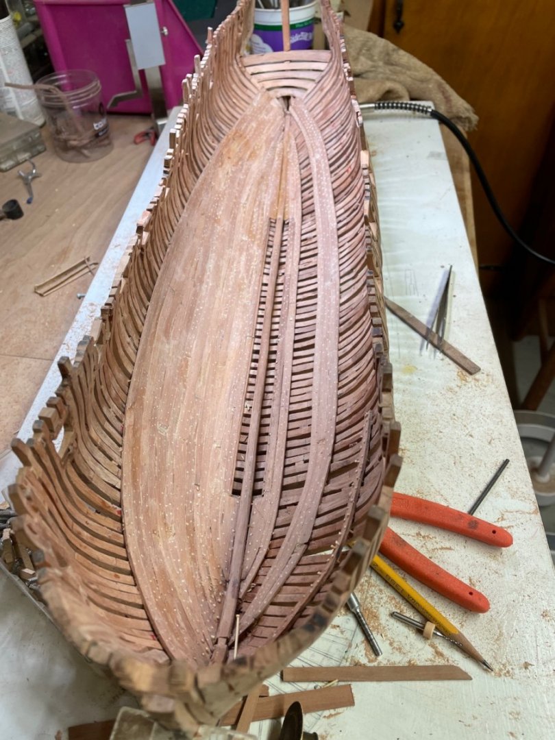
I’ve started the lower deck planking. The “spring” strips (for lack of a better term) work well to tighten the planks together initially. Problems of symmetry still haunt me but am directing more attention to corrective measures as I proceed.
- 257 replies
-
- 8
-
-
- pegasus
- Swan-class
- (and 1 more)
-
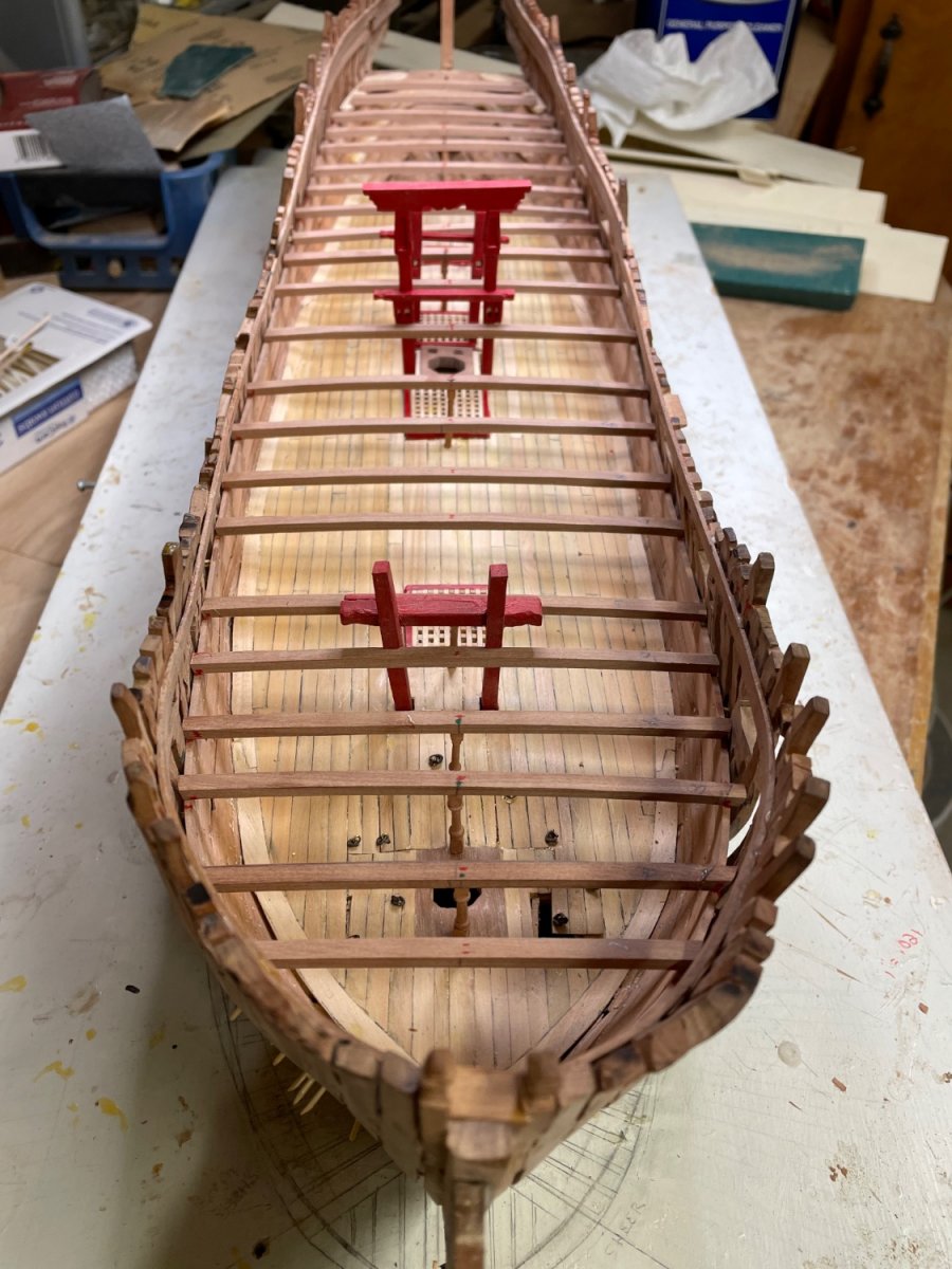
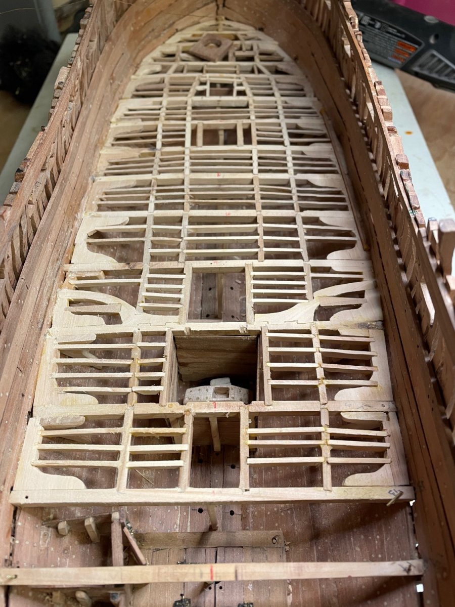
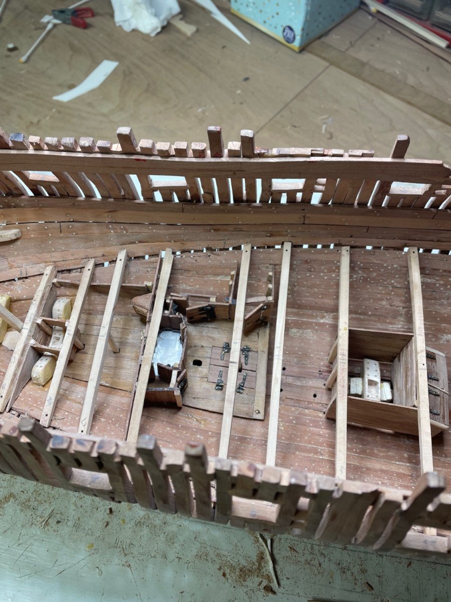
My narrative didn’t come through. Your’e likely wondering why I would post pictures of such a poor job of deck framing…It demonstrates how one can’t be too attentive to symmetry. Even with a framing plan taken from the book and drawn to the particular dimensions of my build, and what I thought was careful measurements, the drift of port carlings to starboard in the beginning accumulated significantly before I recognized it (see top photo). Rather than start over, since the framing will be hidden, I elected to make an abrupt correction with the few remaining beams. Not a pretty result. But a lesson learned, as noted by Kevin previously. Turning the whole model/building board on a bench with limited space in order to sight fore to aft is difficult, but now I see the need to do so frequently.
- 257 replies
-
- 6
-
-
- pegasus
- Swan-class
- (and 1 more)
-
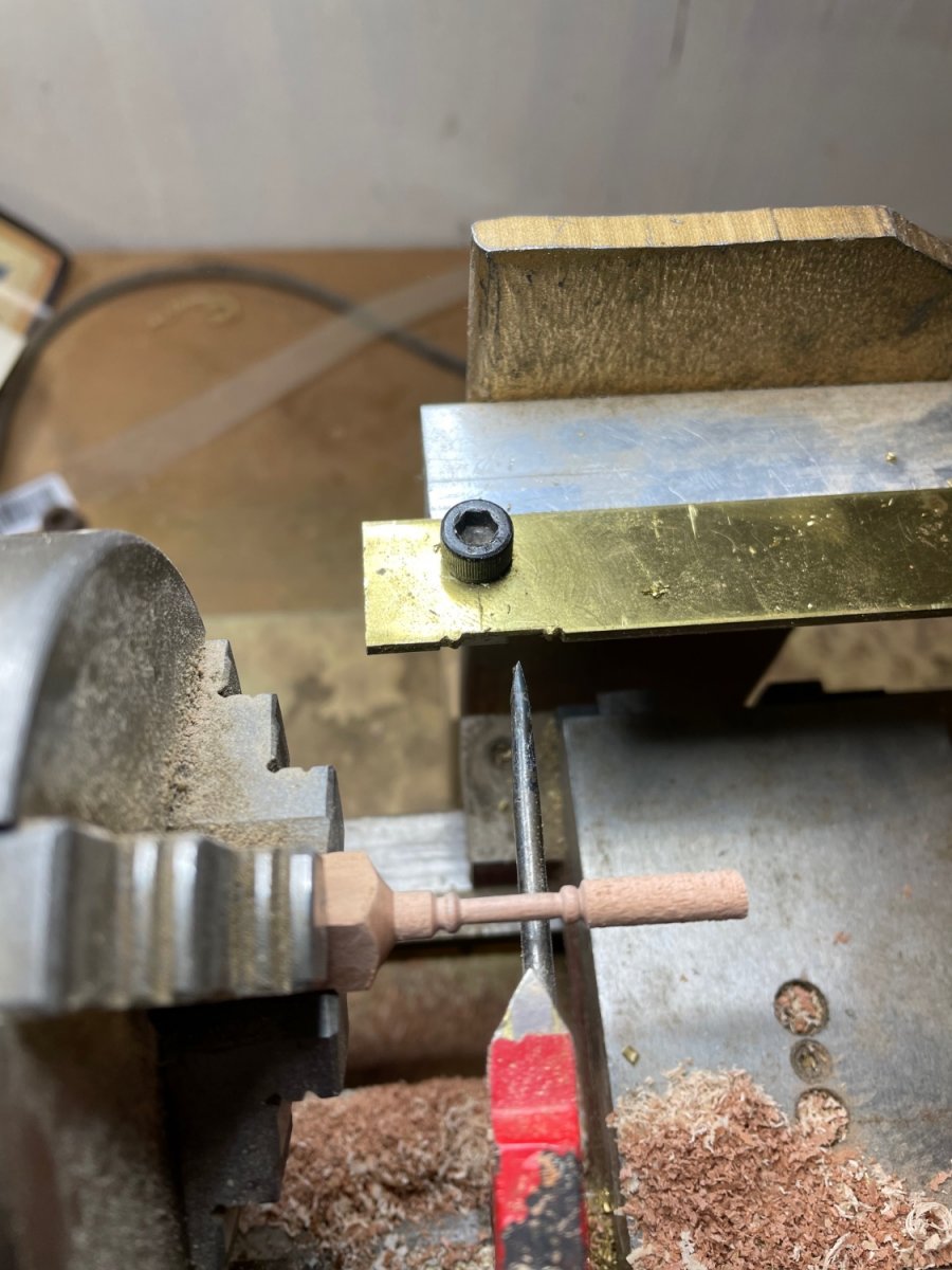
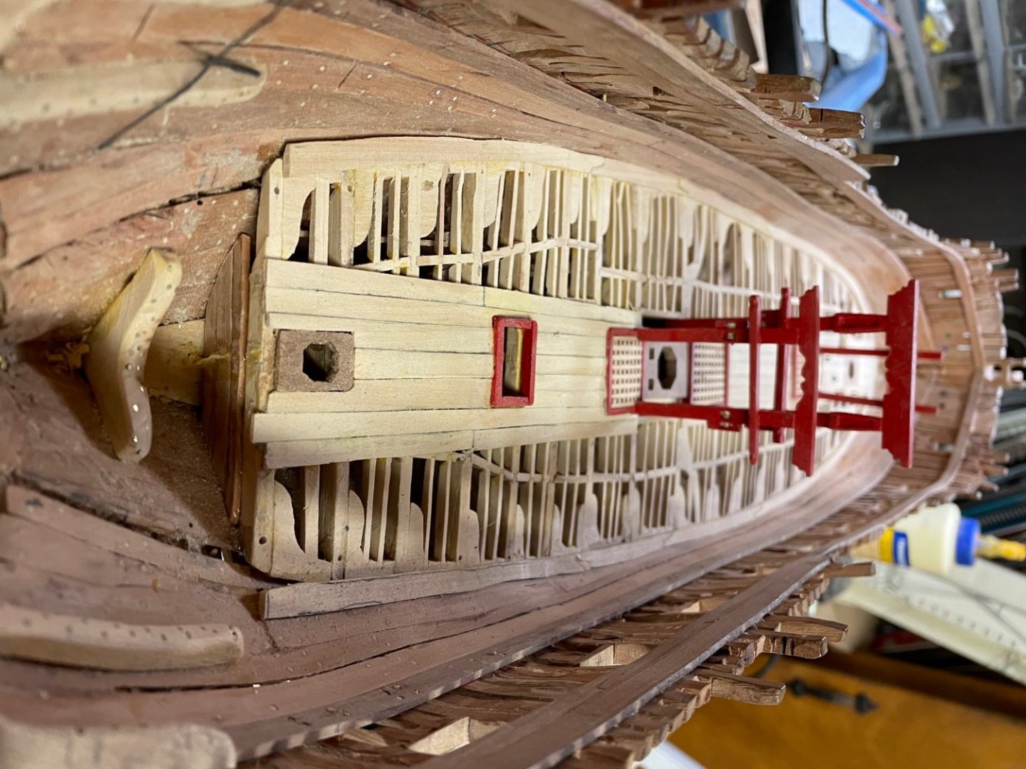
Kevin has provided the number that I needed, of 53” from upper deck to pin top. That dimension should be constant, regardless of which model one is talking about. Now I can apply that number to my own model’s dimensions and arrive at a total pin length and have a pretty good idea of where to place the cross piece in advance. We’ll see. Maybe I’ll have to remake the assembly later, but I’m hoping not to. Anyway, it’s been a good lesson in planning ahead. I appreciate all the feed back. Henry
- 257 replies
-
- 2
-
-
- pegasus
- Swan-class
- (and 1 more)
-
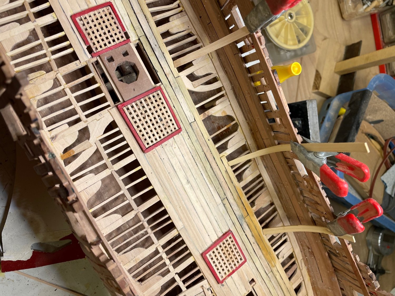
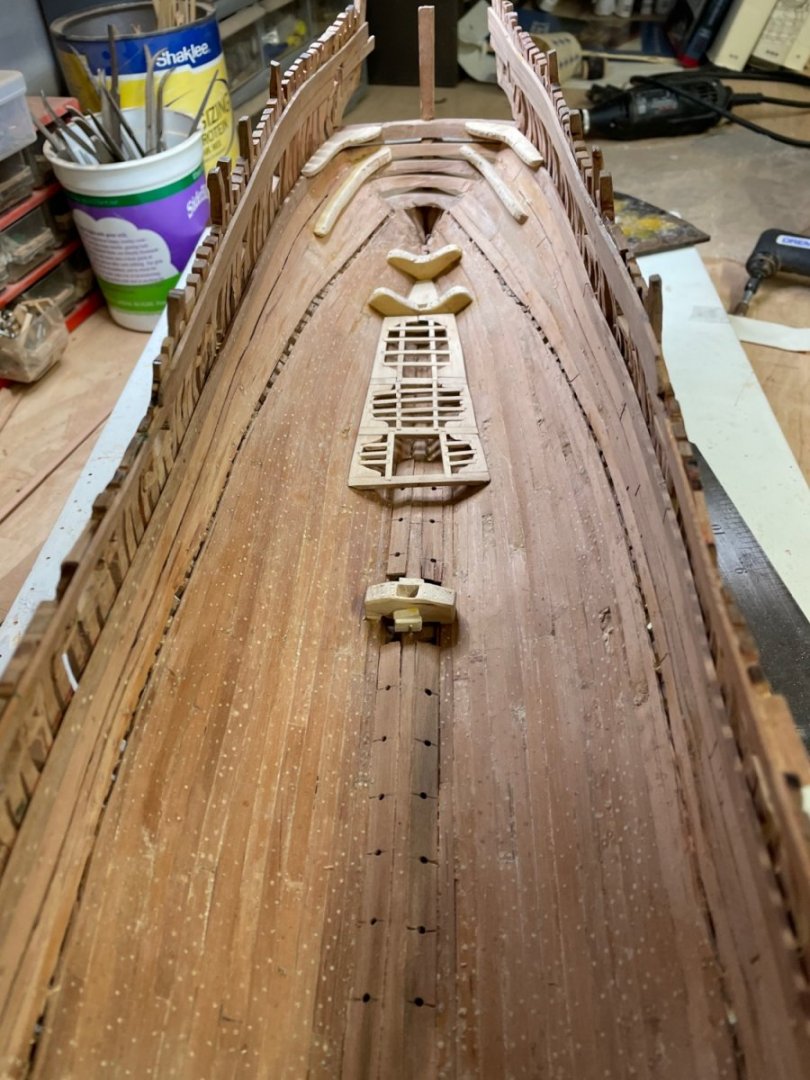
Thanks t Levine. I have emailed the RMG FOR the plans I don’t have. Meanwhile x, I’ll continue with my crude attempts to follow the book. Many errors but managing to get around most of them. One I just discovered relates to the location of the riding bit pins. The platform cut outs are about 1/2” aft of beam #5. So, having installed the platforms and beams, I am in the process of advancing the cut outs forward using a #11 blade and handle inserted below deck. It seems to answer well. In other regards, the decking seems to be going well. Had to remove one ledge for access.
- 257 replies
-
- 3
-
-
- pegasus
- Swan-class
- (and 1 more)
-
Help me out with those numbers a bit. .101( inches ?) from what to what.
-
Kevin, thanks so much for your kind attention to my riding bit delemna. My problem actually is not the location of the pins, but their length. So, I measured the distance from the bilge to the top of the lower deck beam #5 in my build and added that to the measurements on your note to the top of the pins and came up with a pin length of 4.069”. Does that make sense? If so, I am left only with the remaining question of where you derived the measurements on your note…. Henry
-
Kevin, thanks so much for your kind attention to my riding bit delemna. My problem actually is not the location of the pins, but their length. Maybe if I knew the height of the pin tops relative to the upper deck, I could apply that measurement to my model and come up with the correct pin length overall. Even a photo from the side of a completed model would help, if it showed the riding bits. Henry
-
If I use your drawing, it looks as though the various dimensions, when added up, come to 4.148” in 1/48. However, you’re confirmation would be comforting. Henry
-
Hi Kevin. Thanks for that. However, the video doesn’t help me with the issue of the overall length of the riding bit pins ( (or height). Where did you get that from? Henry
-
I appreciate the recommendation of construction of the riding bits as one frames the fore part of the lower deck. However, I’m wondering where the height of the pins is specified. Henry
- 257 replies
-
- 2
-
-
- pegasus
- Swan-class
- (and 1 more)
-
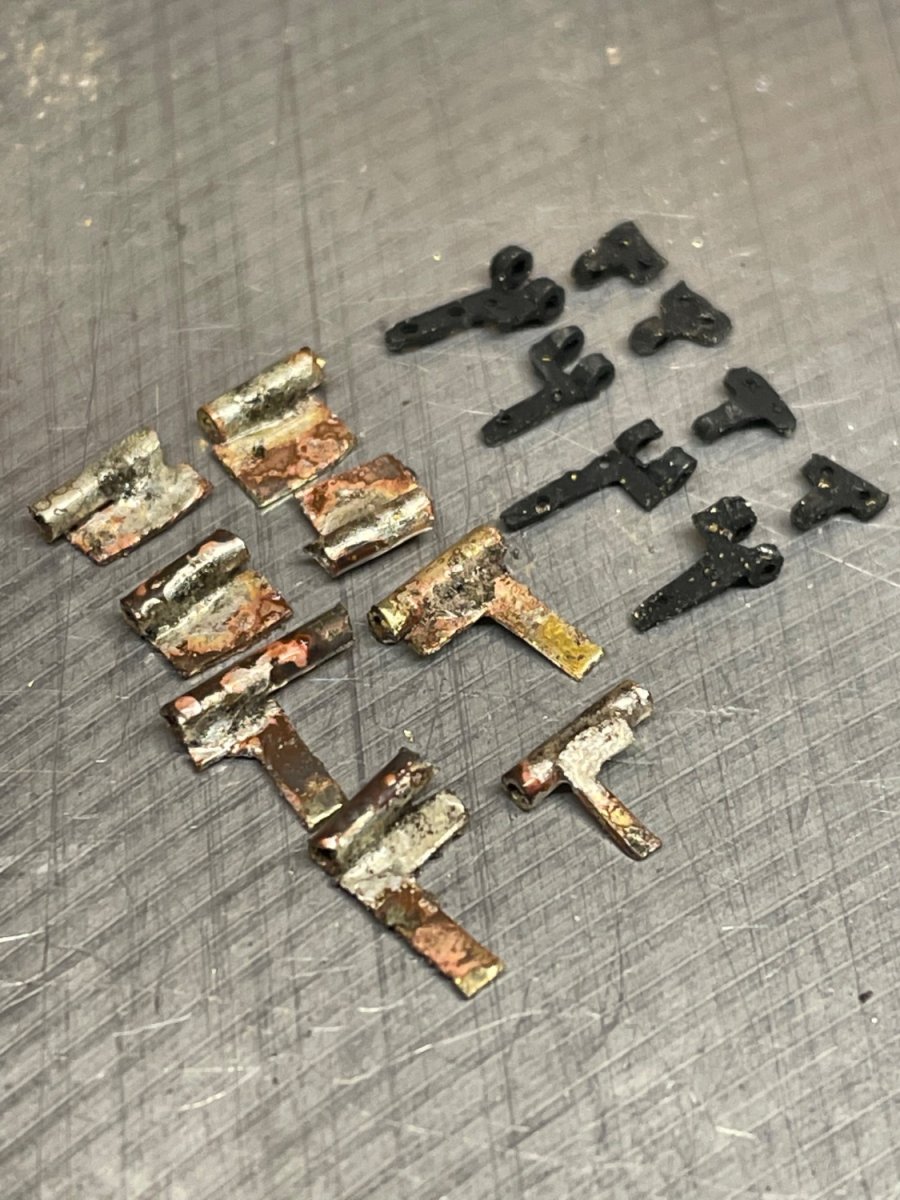
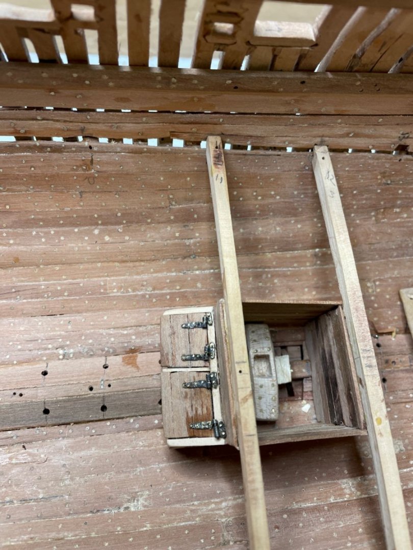
Very hard to scale real hinges down. So far, all are too big. Just received tubing .0126 “ iD. We’ll see if I can work these down to 1/48… When I started this build, I had the plans for framing and spars provided with the 1st volume of David and Craig’s series. But they don’t provide framing for the decks or deck furniture. Where are those available?
- 257 replies
-
- 2
-
-
- pegasus
- Swan-class
- (and 1 more)
-
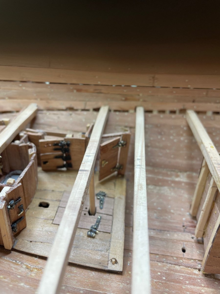
Making progress on my second iteration. So far I’ve followed the posts of Kevin Kenny and Stuglo with great appreciation and admiration. Your skill level is way beyond my own. I find myself spending hours on improving my hinges, trying to make them smaller and smaller. The key has been perfecting my silver soldering technique. The stronger the joint, the more I can file them down to the desired size without the joint failing. I’ve not yet made a decision on how, and whether to display the interior in the final product. So for now, I’m doggedly applying all the interior detail. If nothing else, it’s a fun process and serves to improve my methods. After all, Isn’t that what it’s all about! It’s a cold morning in eastern Massachusetts. Great weather for making progress in the model shipyard.

- 257 replies
-
- 10
-
-
- pegasus
- Swan-class
- (and 1 more)