HOLIDAY DONATION DRIVE - SUPPORT MSW - DO YOUR PART TO KEEP THIS GREAT FORUM GOING! (83 donations so far out of 49,000 members - C'mon guys!)
×

Kenchington
-
Posts
709 -
Joined
-
Last visited
Content Type
Profiles
Forums
Gallery
Events
Everything posted by Kenchington
-
 As expected, I have been proceeding very slowly with this project but I have scanned the card model and enlarged it to 1:12. Reproducing the strake diagram then looked simple but the strakes were too long to be printed on letter- or A4-sized paper, so I have divided them up into groups and turned them until they fit the page diagonally. The stem, keel, wedge and sternpost were nearly as easy, being drawn in profile in the card version -- except that that has the transom in two layers, with only one inset into the post. That needed a minor adjustment to the cut-out on the after face of the post, to match the full thickness of the transom. I have also marked in (with grey shading) the half-lap joints between the keel and the stem and post, following their representation in McKee's Figure 3. In a lighter grey, I have marked the faying surface on the post, where the hog will lie across it. All parts in that drawing (stem, keel, wedge and post) are sided 2 inches (full-size). As with the strakes, I have had to rotate the image to get it onto one page: I won't waste MSW's resources by attaching the strake drawings here but, once I have the full set ready, I'll be happy to share with anyone interested. Trevor
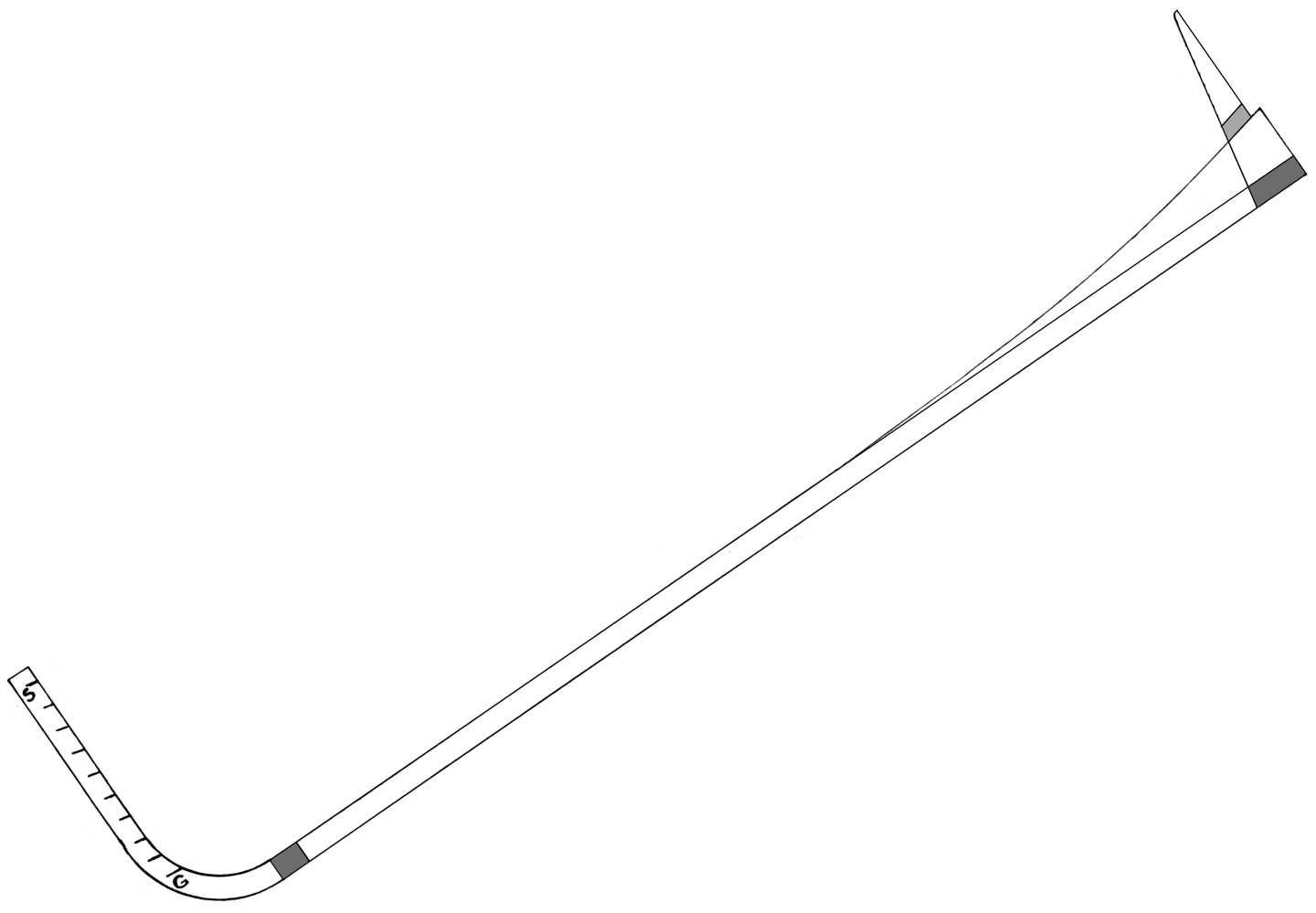
-
Nice joggling of the planks! Trevor
-
Sail feedback request, Mondfeld method
Kenchington replied to travis's topic in Masting, rigging and sails
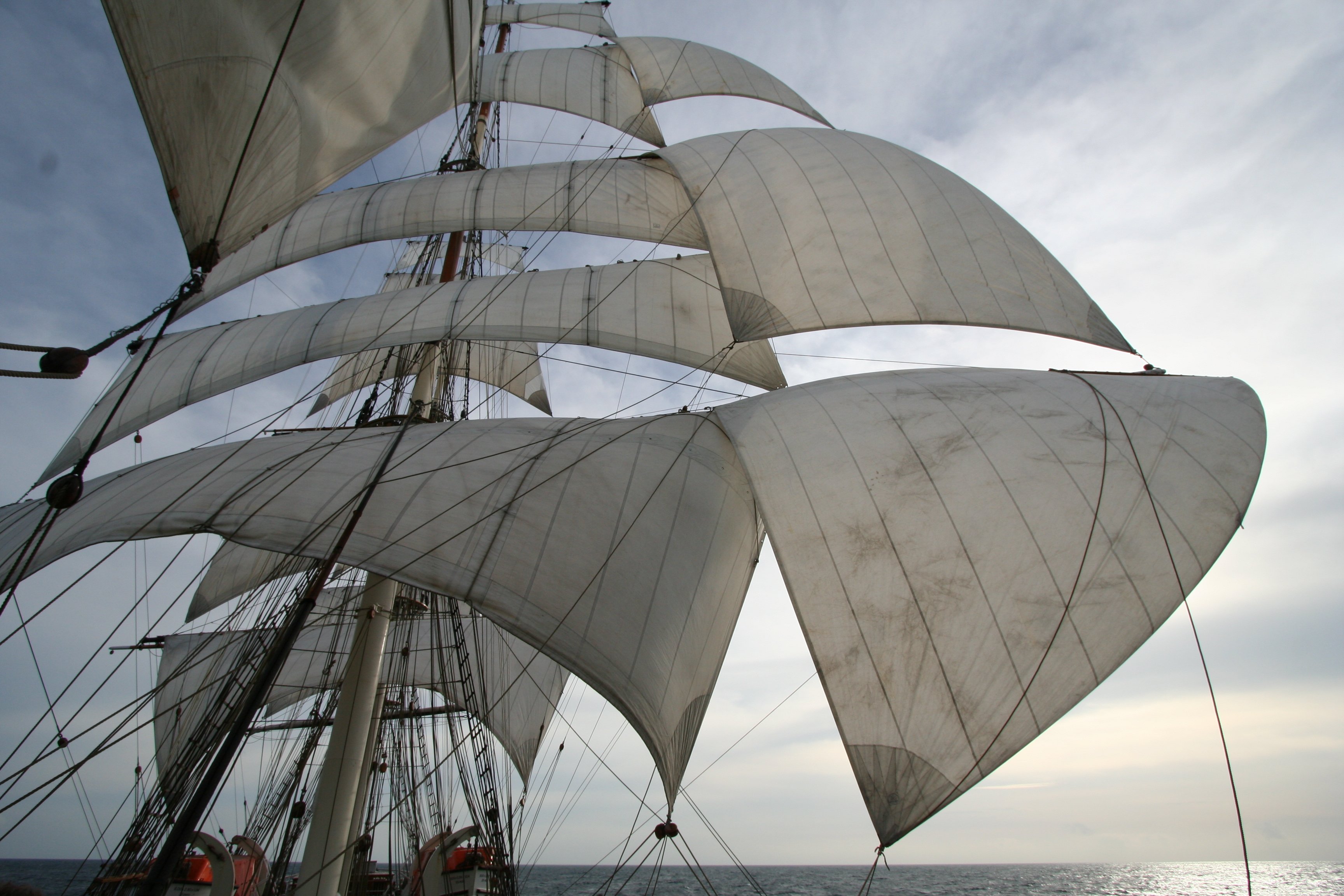
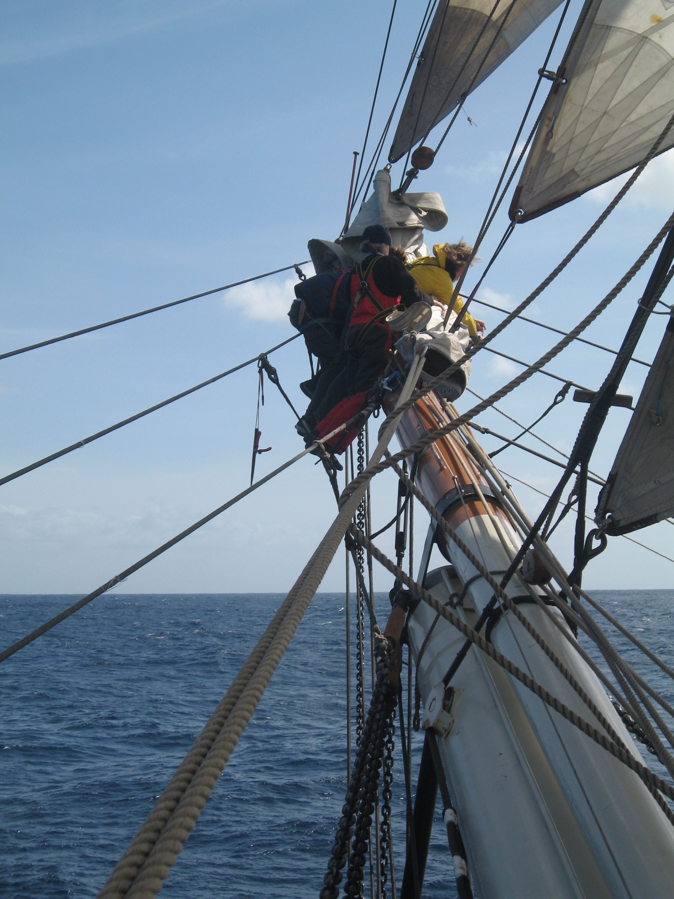
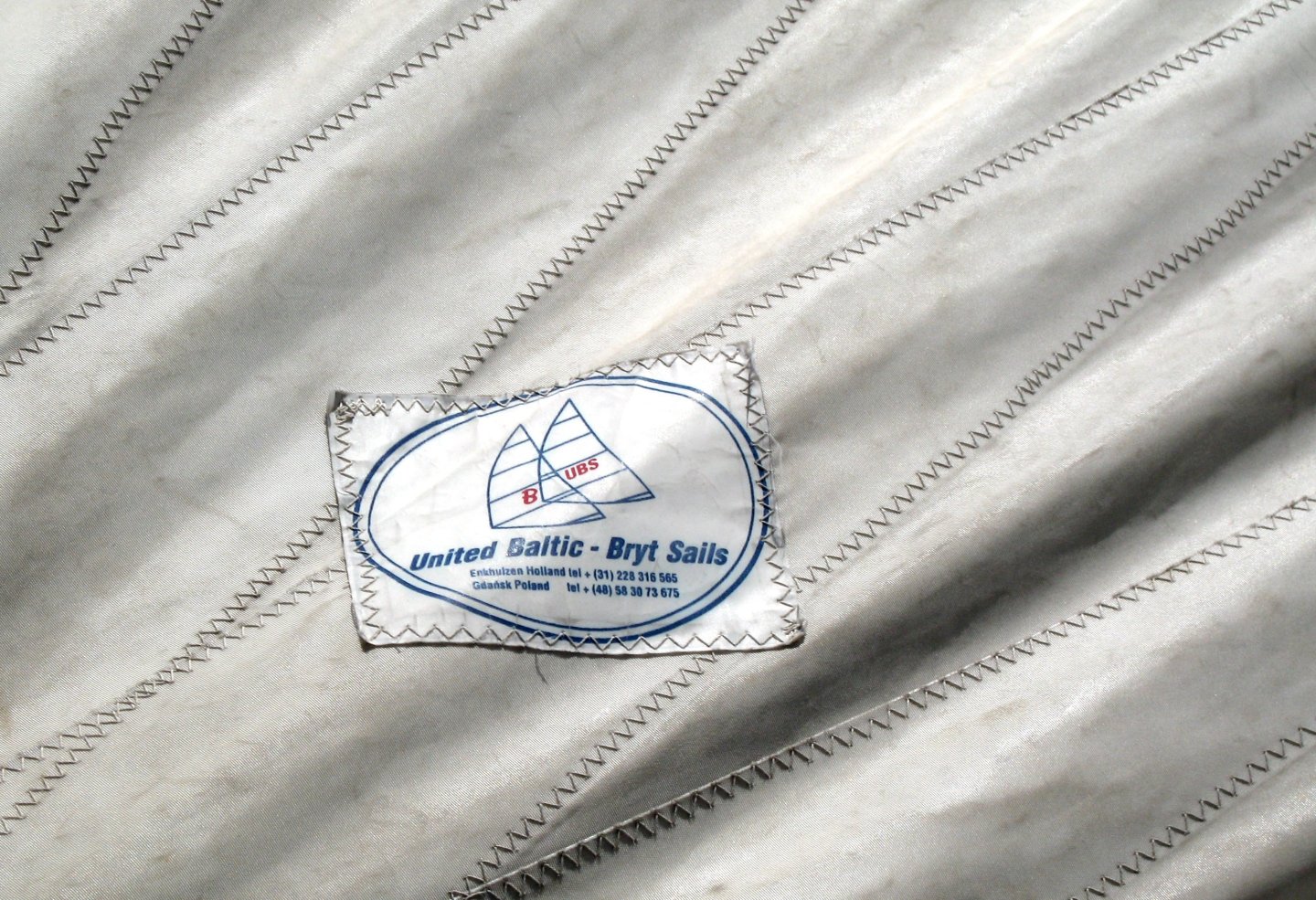
Maybe I should add some other evidence. These are modern synthetics (probably Dacron) and machine-stitched but a full-size squarerigger's sails, when in use, can look like: Note that seams, tablings and various reinforcing pieces are visible but stitches are not. Alternatively, in close-up, the same sails look like: Hand-woven flax-and-hemp sailcloth would have a much coarser weave, of course (and hand-stitching doesn't give the zigzag effect). But an argument for the Silkspan approach anyway. Trevor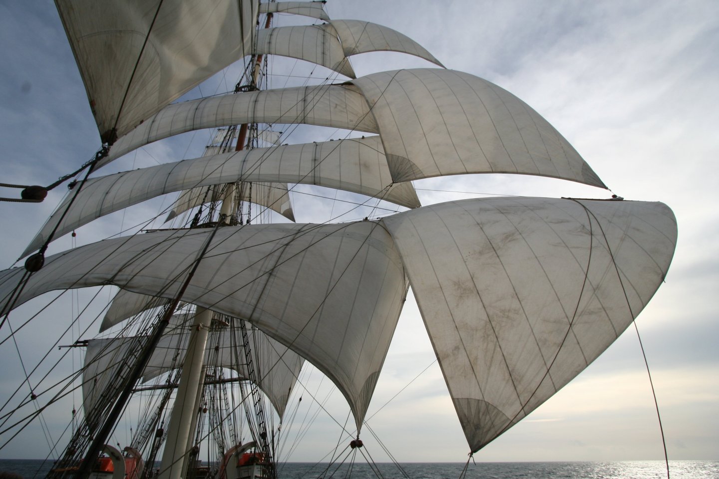
-
Sail feedback request, Mondfeld method
Kenchington replied to travis's topic in Masting, rigging and sails
I have to agree with @druxey. In fact, as I move towards sailmaking for my current build, I was going to post something about scales and sails. I'll not put that here but the points I may yet work towards are (1) if you can see the warp and weft of your canvas, then it is out of scale and (2) unless you can make cross-stitches at finer than 200 to the inch, then any sewing will probably be out of scale too. When sailmaking by hand, stitch size depends on needle size and needle size has to match the weight of the canvas. I have a bag made, by the sailmaker on the big Russian barque Sedov, from a fragment of one of his ship's old sails -- so some synthetic equivalent to double-ought storm canvas. He worked four stitches to the inch -- 240 to the inch at 1:60. Good luck trying to replicate that! Anyone who likes the look of sewn model sails should go with their preference, of course, but they won't be to scale. Trevor -
At the risk off hijacking Jim Lad's thread ... I had forgotten the sad tale of Admiral Karpfanger. By 1939, very long range radio communication was fully possible, of course, so the notable point for present discussion is that a sailing ship fitted as a German training vessel in the '30s carried modern equipment and a radio officer. Maybe that adds to the odds that Herzogin Cecilie had transmitting capability in 1912-14. We know that neither she nor the other Aland barques did in the 1930s. What of the "Flying P" ships before 1914? Some had aerial spreaders at the mastheads but they were operated as pure cargo carriers, not cadet ships. Trevor
-
I would leave it as you have it. Bluenose II does not have extra-wide margin plans around her house, so yours is closer to the prototype than the kit version! Trevor
-
Discharge orders could hardly have been received without the ship being able to transmit, as nobody ashore would know when she came within receiving range. Transmission would have needed lots of electric power that was not available on a sailing ship -- even if the economics of the operation permitted carrying a licensed operator, which would have been out of the question in the 1930s grain trade. (The meagre freight rates didn't even permit either insurance of the ships or living wages for full crews.) Weather reports might have been possible, if they were broadcast in that era, but would have needed someone able to read morse transmitted at the rapid rate of professional operators ashore. That's a skill that one of the mates might have developed but it was rather specialized expertise. The range at which signals might be received depended on the power of the transmitter (along with much else). Before 1914, Marconi's shore stations were sending signals that were received 2,000 miles away and more -- though perhaps by more sensitive receivers than the sailing ships carried. Trevor
-
Those knees do need lots of careful work but you made a fine job of it! Trevor
-
Thank you for that pointer to a work I had not seen! Addresses spar, rigging and sail plans, not just the more-common hull designs. However, in that era, "model" could mean a two-dimensional representation -- as in a draught. Miller's "Compleat Modellist" is available in the Internet Archive and my quick scan didn't notice anything dealing with 3D models. Maybe I missed it. Trevor
-
Of course you should show her as she was! Besides, it will make for a useful educational point for future museum visitors. I doubt that any sailing ships carried Marconi Company operators or those of the few competing companies (though perhaps the Duchess did in her training-ship days?), so I assume they only had receiving capability and nobody aboard able to read incoming rapid Morse. Hence my guess that the intent was mostly about time signals. Wikipedia claims that those were transmitted from 1905 but presumably not with enough range to reach a ship beating around the Horn. Still, an opportunity to check the chronometers before making landfall on the European coast could have made the cost of the installation worthwhile. Trevor
-
Lovely draping of those rope coils! But radio aerials on a sailing ship have always seemed, to me, to be a particularly weird historical inversion of technological advance. I think (though I have never confirmed) that the Duchess and her contemporaries were fitted for receiving radio time signals specifically. Those made possible the checking of chronometers, without needing to take lunar distances -- a very demanding skill that could finally be discarded just a few years before the Panama Canal put an end to new-building of deepwater sailors. Still feels odd! Trevor
-
Wikipedia says "Established 1843". Their 1934 catalogue is on-line at https://usvmyg.org/archives/a-catalog-of-model-yachts-model-ships-yacht-fittings-stevenss-model-dockyard-1934/ Looks like their variety of fittings 90 years ago would put to shame most modern suppliers. I wonder whether they expected to sell mainly to enthusiastic amateurs or the people who built large models for shipbuilding companies and passenger lines? Trevor
-
Nate's PANDORA in 3D
Kenchington replied to 3DShipWright's topic in CAD and 3D Modelling/Drafting Plans with Software
Thinking a bit more on your main question: If the hinges were aligned with the shape of the hull, the door could not open towards the cabin, as its outer edge would swing down when opening and would soon hit the deck. I doubt it would open outwards, as there was so little space in the quarter gallery. So the hinges would have to be arranged vertically, with the bottom of the door near the cabin-side edge of the ship's side and its top near the outboard edge. A thought though: Wooden ships twist and bend in a seaway. A close-fitting door can jamb -- which would be very embarrassing if the captain found himself shut in his gallery! I wonder whether the doors had wide gaps all around or perhaps were taken off their hinges and replaced by curtains when at sea. Trevor -
Nate's PANDORA in 3D
Kenchington replied to 3DShipWright's topic in CAD and 3D Modelling/Drafting Plans with Software
That's a common oversimplification but probably not relevant to the layout of a warship's officer accommodation. It is true that, by the late 19th Century, the English working class was generally undernourished and under-developed (though not their Australian and Canadian cousins). The military enlistment records from 1914-18, which include height, weight and chest size, confirm that. But skeletons from earlier archaeological contexts often suggest something different, perhaps because people were better fed when most worked on the land, rather than in industrial towns. Besides, the officer class had better feeding in childhood -- though sea officers maybe not in teenage, once they were afloat. I would guess that frigate captains were of average height by modern standards. Where they differed from us was in expectations: We want to be able to stand upright. Earlier generations of seafarers, yachting types as much as those employed at sea, accepted that that was a luxury only available when on deck, with the sky above. Through to the mid-20th Century, warships were designed as ships for war, with their human machinery tucked into odd corners unsuited to less flexible equipment. I suspect that all concerned expected a frigate's quarter galleries to be nicely symmetrical when viewed from outboard, rather than ergonomically optimized for the end user. If that meant that the captain had to bend double when using the facilities, at least he was better off than the Lieutenants, who had to endure the indignity of chamber pots! Trevor -
It's not for anyone else to tell you what to do with the model but, if it was my choice to make, I would not "correct" the lead of the braces. Besides the risk of ending up with more problems than you solved, I think the model has its own history, as an artifact in its own right, as much as a representation of a full-size prototype. If it were my call, I would let Ragnar's work stand, in part as a monument to him, his family and the trials he went through to give them a better life in California. Seems that was an uplifting story itself! Trevor
-
Billings have given you a black ball as the day shape for a vessel at anchor but I expect they meant to provide either two cones (shown point-to-point) or else a fish basket -- either of which is the mark for a vessel fishing and unable to manoeuvre. They are only to be shown while the boat actually has her fishing gear in the water, hence on a rope halliard as you have shown, but trawlers often come from the shipyard with one shape or the other welded in place on rod rigging. Either way, you have created a very fine model! Trevor
- 62 replies
-
- 1
-

-
- Nordkap
- Billing Boats
- (and 1 more)
-
Your model does not have quite the deck layout that Crothers showed for Young American but maybe close enough for a kit of a hundred years ago. There's a feel to the model of a seaman-made example, with some fantastic detail (such as the splices) but also gross simplifications (e.g. no stuns'l gear). But I'd doubt the involvement of an actual clipper sailor: Leading the braces of the yards on the mainmast (except those of the mainyard itself) forward looks wacko, for one example. Then there's the three separate halliards for the spanker gaff (instead of just peak and throat). Those speak of an enthusiastic landsman. It's a truly lovely model all the same! Trevor
-
I'm not fully sure what to look for either. von Brandt's "Fish Catching Methods of the World" would be a good starting point, though only as a broad-brush overview. But little of it is available on-line and my copy is in storage, where I can't get to it until next week. The UN's FAO put out volumes on fishing gears in the 1950s and '60s. I can access those but only when I get into the Bedford Institute library and that would be next week at the earliest. How's your German? If you can handle it, there is the "Handbuch der Seefischerei Nordeuropas", published in multiple parts from the 1920s to the 1950s. The only part that I have dipped into had some nice illustrations of German fishing boats and their gears. You could do worse than starting with the Wikipedia page: https://de.wikipedia.org/wiki/Handbuch_der_Seefischerei_Nordeuropas Trevor
- 33 replies
-
- 3
-
-

-
- Fischkutter
- Laser Creation World
- (and 1 more)
-
As others have said, forget the AI, Bryan. How your cutter should be rigged depends on date, place and the type of fishing you intend to represent. Small fishing boats work in restricted areas (often very restricted) and can be adapted to suit local conditions (unlike ocean-going freighters, for example). Indeed, scraping a living from the sea usually means that every detail has to be optimized for efficiency under local conditions. Amidst other errors, AI wants to show your cutter working beam trawls from booms. That would likely be right in the 2020s but less so if you aim to show a boat in the 1960s, when otter trawls dominated. A Gulf of Mexico shrimper of that era would have worked a double- or triple-rig (two or three trawl nets, towed side by side) but I suspect that German cutters still worked single nets then. You need too decide on all that before worrying over which line led where! Trevor
- 33 replies
-
- 4
-
-
-
- Fischkutter
- Laser Creation World
- (and 1 more)
-
She's not a close fit to Cutty Sark, so either Ragnar was not overly constrained by historical accuracy or else he aimed to represent a different ship. With deep topsails (not split into upper and lower) and skysails on all three masts, she looks earlier than 1869. I'd guess a Yankee clipper, rather than a British-built one. The cabin house straddling the break of the quarterdeck, with skylight and companionway abaft that house, was an unusual arrangement (and not seen on Cutty Sark) but not unknown. @ClipperFan may be able to identify a specific prototype. Trevor
-
Bower anchor project by Sizzolo
Kenchington replied to Sizzolo's topic in - Build logs for subjects built 1751 - 1800
The use of a coloured yarn as a brand mark is not unusual. Marlow used to run a black one in their ropes and maybe they still do. Then again, I think some jurisdictions require marking of rope that meets specified safety standards and the like. Melting used to be a good test of man-made versus natural fibres. I don't know whether the current crop, Kevlar and the like, melt but they probably do. All of the natural fibres will char and burn but never melt, of course. Trevor -
Bower anchor project by Sizzolo
Kenchington replied to Sizzolo's topic in - Build logs for subjects built 1751 - 1800
The lay that works with modern machinery and what worked when sennit was laid up by hand are not the same. There's more than one way that it is done now (flexible yacht ropes have many more strands and can have cores separate from the surface layer) but there were/are even more alternatives when making sennit. Trevor -
Bower anchor project by Sizzolo
Kenchington replied to Sizzolo's topic in - Build logs for subjects built 1751 - 1800
Looks to me like machine-made 8-strand mooring line -- late 20th or early 21st Century. Without examining the material directly, I can't say what it is made from, only how it appears.But how it appears is as UV-degraded polypropylene, originally glossy black. What colour the marker thread started as, I'd not want guess, though certainly something pale and contrasting with the black. Trevor -
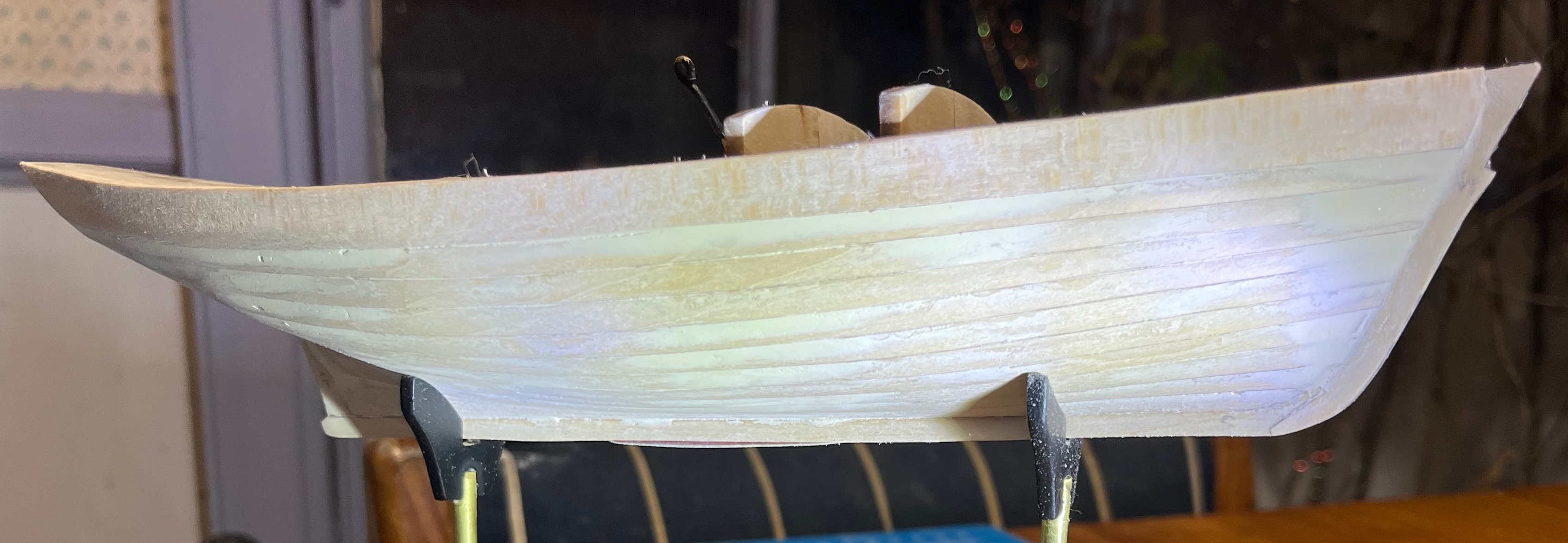
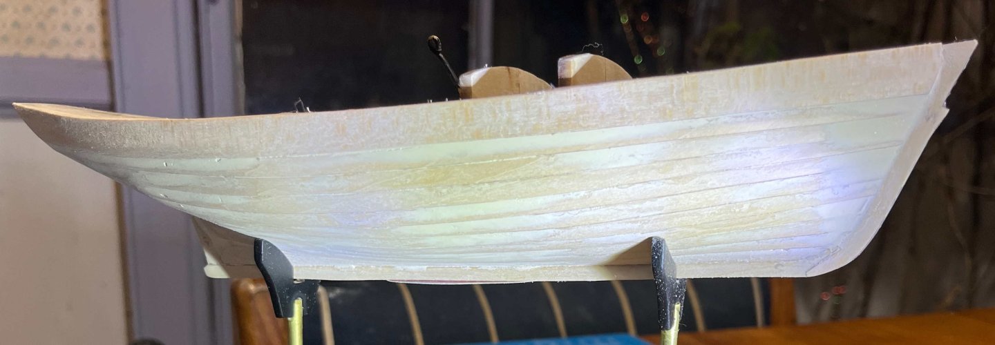
Four rounds of applying filler and five of sanding has brought me to: Good enough to be getting on with -- and a whole lot easier than I had been fearing! Next step in the instructions calls for fitting the toe rails, then the rub rails. However, I aim to have those in contrasting colours, so I will mask off the rub rail area and the deck, then spray on some primer tomorrow. Probably spray, sand, fill, spray again and repeat, but time will tell. Trevor
-
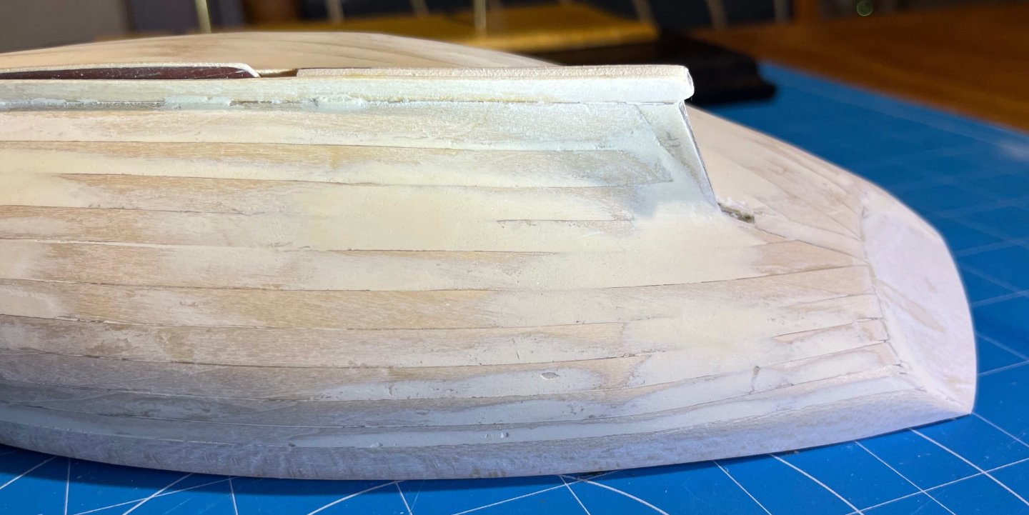
Thank you both for your kind comments! Workboat, yes. So the strakes should be evident as strakes, but without a step between one and the next -- each section essentially a series of flats, whereas the outer faces of a yachts planks would more likely be shaped to a curve, to make a smooth surface. Still, I do need to reduce the steps between some of the strakes. JC: I am not (so far) worried about the surface finish of the sheerstrake. Maybe that will cause me some grief but I'm expecting sanding and priming to be enough. Trevor