HOLIDAY DONATION DRIVE - SUPPORT MSW - DO YOUR PART TO KEEP THIS GREAT FORUM GOING! (Only 36 donations so far out of 49,000 members - C'mon guys!)
×

Kenchington
-
Posts
679 -
Joined
-
Last visited
Content Type
Profiles
Forums
Gallery
Events
Everything posted by Kenchington
-
 Moving right along ... I painted and fitted the two pieces bent yesterday. They will need a touch of filler and paint once the cockpit coamings are in but OK to proceed now. So I fitted the broken-off after portion of the framing, with a couple of cocktail sticks pinned on a temporary battens to support everything until the deck takes over that role: And that means that I finally ready to start making this mess look like a boat! Trevor

-
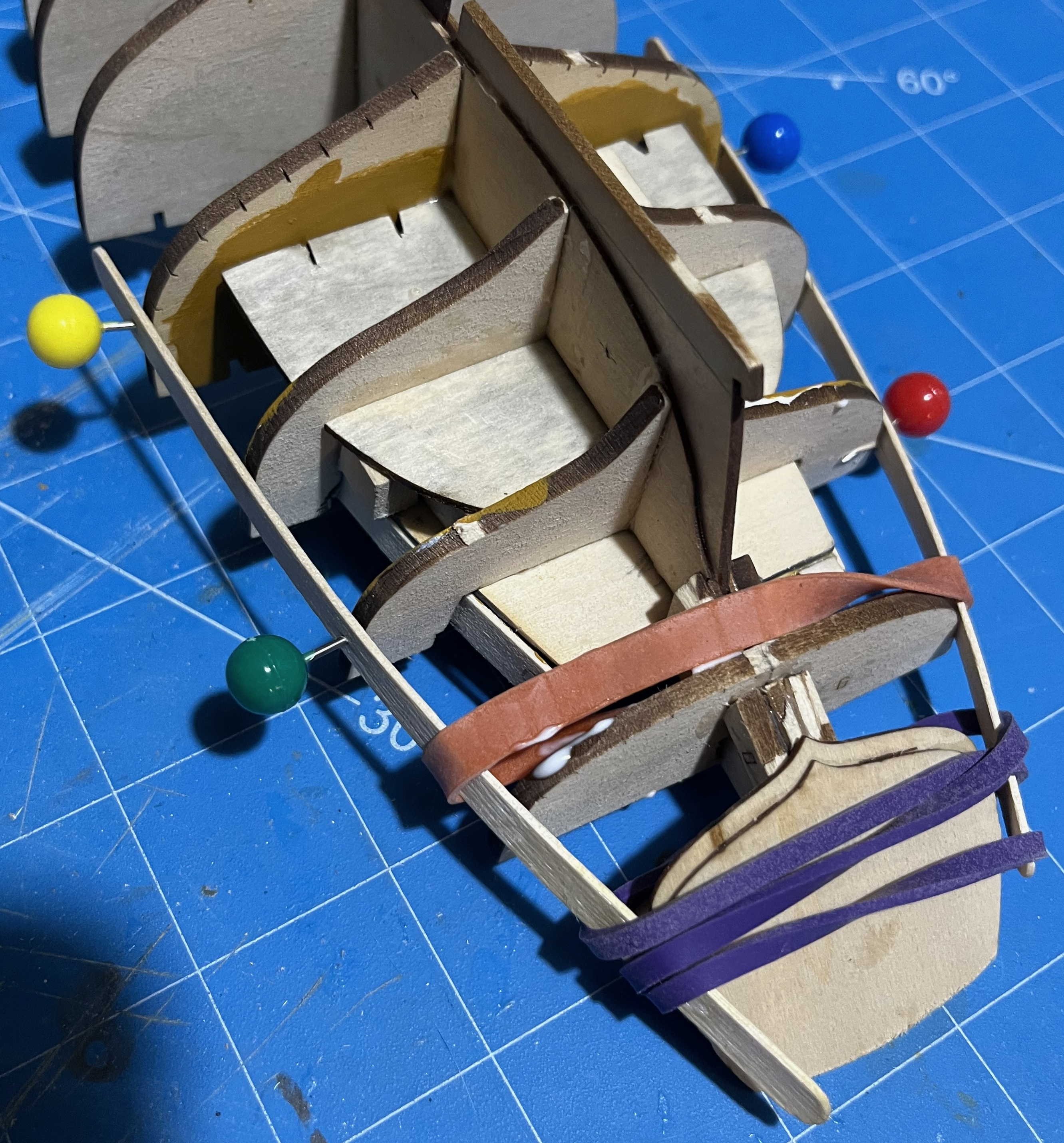
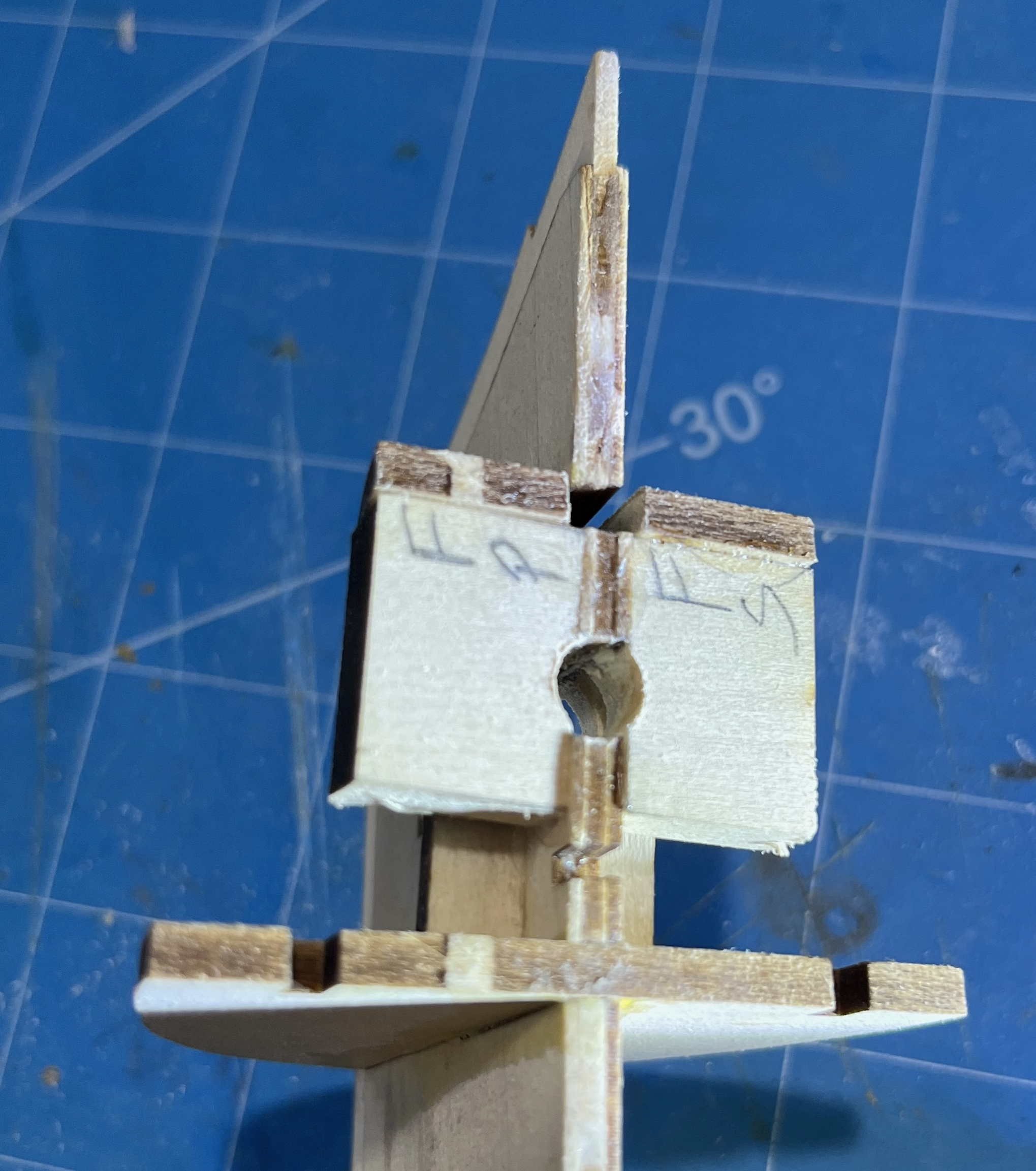
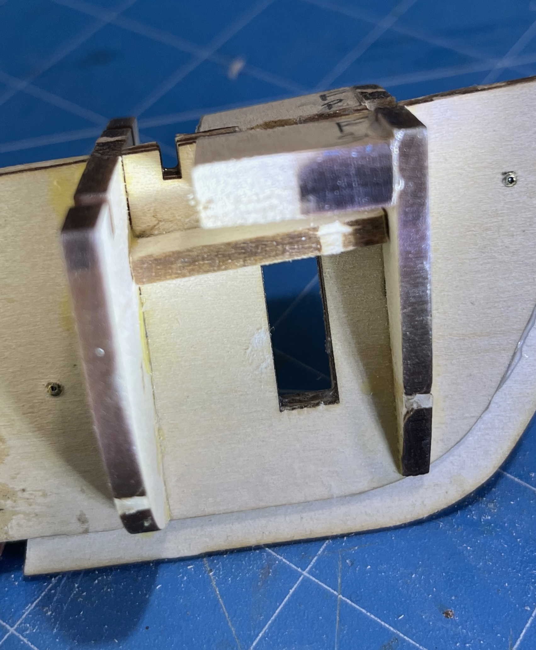
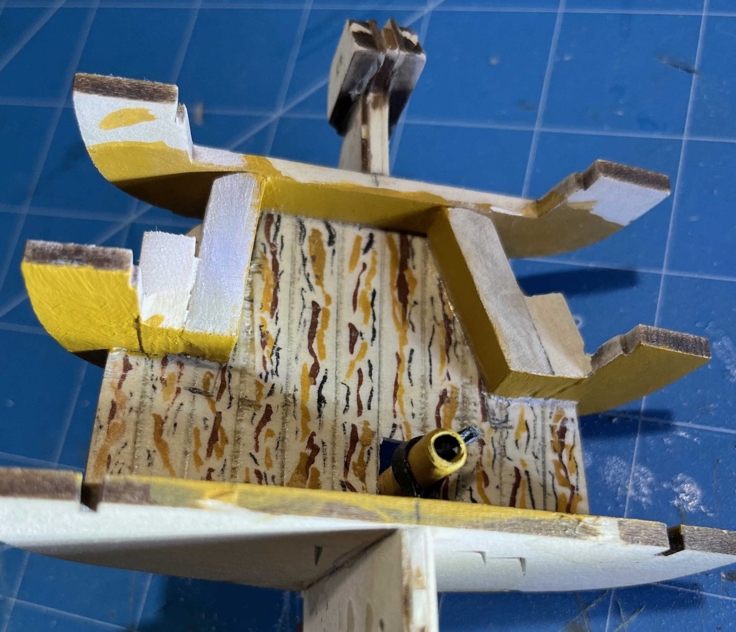
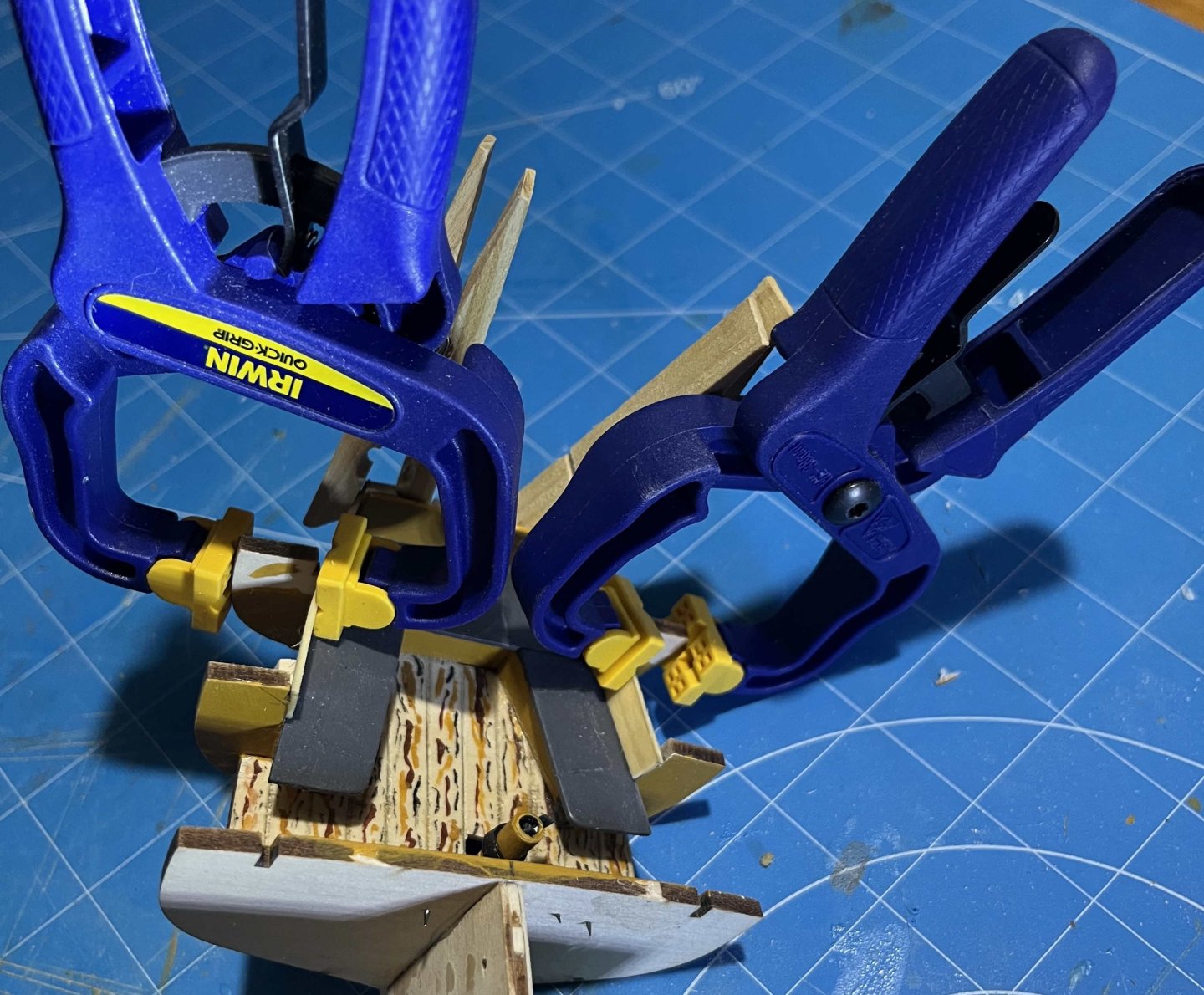
Finally got some serious time for model building again. (Editing a manuscript to suit the peculiar format of a particular academic journal can be a ***!%$$*** pain!) Not that I have been entirely idle, but my attempts at completing the sloop's cockpit went off the rails, so I had to back up, fail again, then realize that there was an easier way. The underlying trouble is something I mentioned in Post #8 of this thread: Plank-on-Bulkhead is a very practical approach when modelling a fully-planked hull, without the complications of the structurally realistic Plank-on-Frame alternative. However, P-on-B doesn't work with models of open boats, which necessarily display the internal structure to a viewer. Substituting a few bulky bulkheads for more-numerous but slimmer timbers can only leave an ugly misrepresentation. (Hence (presumably) the choice of dory and pram for the first two steps in the Shipwright series: Each has a simple internal structure that could be represented accurately without being overly demanding for those of us starting out.) But what of the Muscongus Bay boat? She is mostly planked over but the cockpit is open (in the sense that an open boat is open). The kit is designed for P-on-B construction anyway and yet the bulkheads show as big, chunky, unrealistic features -- as the photos in the instructions, and multiple build-logs, confirm. The proper answer, of course, would be to substitute Plank-on-Frame construction between Bulkhead 6 and the sternpost and between the deck and the cockpit floorboards. If the kit was designed to have the bottom and topsides planked before the deck is added, I might have gone that route, but the model actually needs the deck for strength before fairing and planking begins -- while the deck would seriously impede access to the area to be framed. Working around all that sounded far too demanding, so I scratched that idea. An alternative was suggested by another simplification in the kit: The very limited evidence we have of the Muscongus Bay centreboarders suggests that the cockpit seats were light and simple -- probably supported outboard by stringers on the top timbers, with a pillar to support the inboard, forward corner. Yet the kit has a solid block each side as a seat support. And that looks a whole lot like the front of a cockpit locker, with the space under the seat closed off. So why not extend the visual simplification and close off the whole space where the bulkheads are visible in models built straight out of the box? I doubt that any lobsterman of 1890 had the interior of his cockpit closed off like that but I am quite certain that he could have done, if he had so wished. So I'm fiddling with reality and going for that appearance. Besides, I aim to show a working lobsterboat at work, which means that she has to be carrying all of the gear that would be needed within reach: Coils of spare hawser for whatever may arise, likely most often anchoring in deeper water; more coils of lighter rope for repairs to rigging, along with some blocks and shackles; likely a set of spare pump valves; some replacement lobster buoys and buoylines, for ones in danger of parting off; a grapple to drag for traps whose buoys have been lost ... and all the other bits and pieces that boats accumulate, save items small enough to be stowed in the cuddy. If the kit's cockpit seats were shown like those in the few surviving photographs, I would have to model all that. But, by choosing to assume closed-in lockers, I can portray the sloop with all of her gear aboard and yet not create more than a small fraction of it! So that is what I am doing. My first problem was with the kit-supplied seat supports. Their after ends have to be bevelled to fay against Bulkhead #8, which is easy enough. But pressing them in tight while the glue grips makes the angled end slide. So it was out with the isopropynol and try again. Second attempt was just good enough, so I accepted that, then sanded the forward ends flush with Bulkhead #7 -- simplifying construction but also hiding a future mess under an overhanging seat end. I got into trouble trying to lay thin basswood across the forward face of the support and bulkhead. (The material kept breaking along the grain.) So I sawed, sanded and filed the blocks seen in the photo, filling the gap between support and bulkhead. I had painted as much as possible before gluing but, once all was set, there was sanding to get surfaces flush, then careful priming, followed by three coats of yellow ochre on exposed surfaces. The cockpit seats went on top without trouble. Grey paint is best for seats on a work boat, as it doesn't show dirt or (more important) scratches and gouges that cut down to bare wood -- wood that swiftly goes grey! Also: Closed-in lockers require openings in the seats to provide access. I marked those by scribing the surface to indicate lift-out sections. To improve things, I tried painting the grooves black, intending to scrape off the grey when all was done. However, the paint didn't want to come off, so I am left with just the scribing. The kit provides a piece to fill between the after edge of the seats and the deck. I needed two more pieces to cover the inboard faces of Bulkheads 7 and 8, from the seats up to the bottom edge of the coaming. It turned out that those would need to be twisted if they were to meet the ends of the kit-supplied crosspiece, which itself would need stiffening to support the side pieces. So it was time to soften two tiny pieces in boiling water, then clamp them in place to dry: That's as far as I have taken the cockpit for today but I did make one more advance: I aim to give the sloop the rig that Chapelle described, with no shrouds, but I don't fancy the consequences of my clumsy hands striking the top of the mast, if that is only supported laterally by the thin basswood of the kit's deck. So I added "mast partners" at the level of the underside of the deck, with a hole between sized for the mast: I have been making some progress on a display-stand too but more about that once it is finished. Next up: Get the cockpit side pieces into place, add the broken-off after framing, then it will be time for the deck! Trevor


-
Nate's PANDORA in 3D
Kenchington replied to 3DShipWright's topic in CAD and 3D Modelling/Drafting Plans with Software
I don't want to rain on anyone's parade, still less get drawn into an argument, but in a spirit of constructive debate: Maybe someone simplified the draughting and drew the timbers with straight tapers, rather than steps. The lesser siding of the top timbers is still represented in the draught. Yes there are. It is only that the draught was (again) simplified by the chocks that both joined at set-apart the two halves of the pair being shown only for one pair (the ones that frame the forward side of the fifth gunport counting from the bow) and omitted for the others. There I do agree with you and I am left wondering why. My best guess (and no more than that) is that the gunports compromised the strength of the hull so much that the frame had to be adjusted to minimize the weakness, whereas lesser holes could be worked in as an where needed while the ship was being built. I don't understand what you meant by that. So the shipwrights were required to trim the scantlings of the available timber, trimming more in some parts than others? That's no criticism at all. I see no reason to doubt their accuracy. Nor that they were "complete" for the purpose for which they were prepared, though most certainly incomplete as exact representations of the frame of the completed ship. There I must disagree. The author of Shipbuilder's Repository (who did not even put his own name to his book, let alone produce some sort of official textbook) gave recommendations, not rigid rules -- which did not exist. For the details of a particular ship, we must turn to draughts of that ship, the nearest for which details are available or else seek the underlying principles from study of many draughts. Trevor -
Nate's PANDORA in 3D
Kenchington replied to 3DShipWright's topic in CAD and 3D Modelling/Drafting Plans with Software
I (almost) agree with your 77%. (The top-timber siding tabulated in the Repository rounds to 100% of the 4th futtock, not 99%.) But I can't agree that the framing diagram you have presented omits that detail. Setting dividers against the diagram on my monitor shows the siding of the head of a top-timber amidships is close to three-quarters that of the floor -- call it 77% or 78%. More generally, while no one source can be trusted as absolute truth and we need to understand the intent behind each type of diagram, I would suggest that (in general) drawings made by the people who designed and built the ships (e.g. those now in the Greenwich collection) are more trustworthy than modern interpretations -- especially interpretations by enthusiasts whose skills lie in draughtsmanship, rather than ship design or nautical archaeology. Trevor -
I stand corrected. But that makes the evolution shown in the painting distinctly odd -- at least to my eye. The topsail sheets remain taut, with the clews hauled out to the yardarms of the lower yards, as expected. The topsail clew lines have likely been hauled, to aid gravity in bringing the topsail yards down to the lower-mast caps. Again, nothing odd in that. What fooled me is that the lower third of each topsail leech remains semi-taut (not billowing, as the upper 2/3 are), while the bunt of each topsail is stretched to the yardarms of the topsail yard. (That's where I went wrong: It looks like the heads of lower topsails are bent to yards, when it is the bunts of deep topsails stretched.) So what have they done? Taken up tight on the reef tackles of deep reefs on each topsail? I guess that might be an effective way of temporarily reducing the power of the rig, while still keeping some headway, but I don't recall hearing of that before. (Maybe I should re-check Harland's book!) Or should we just question the artist's understanding of sail handling? Trevor
-
Even if a spherical ball could leave the muzzle at supersonic speed (very improbable with black powder as propellant), it would very quickly decelerate. The aerodynamics of a sphere are poor indeed! Trevor
-
Without daring to comment on the potential for "near miss" injuries, I'll suggest that, in naval combat, it was the "splinters" (which could be multiple feet in length) sent flying by the impact of roundshot on the ship's structure that did most of the damage to human bodies. Trevor
-
They certainly look like very similar schooners, if not identical, while Steers' designs (with narrow bow and wide quarters) were a new departure at the time, unlikely to be encountered anywhere but New York. But now we have two versions of the Buttersworth painting, one with a possible signal flag at the fore (blue cross on white) and the other either a plain blue (which the pilot seems to carry too) or maybe a US Navy jack, with stars on the blue. And one last point: The claim that the painting shows Stag Hound with "partially furled sails" is a bit misleading. She has her skys'l yards set down, her t'gan'sl's and royals furled, along with her main course and her cro'jick too But the sense of action and movement (enough that I can almost hear the canvas thundering, just from looking at the image!) comes from her upper topsails being clewed down and her outer jib hauled down likewise -- presumably to slow the ship enough to take the pilot aboard. Those sails are not about to be furled, but will soon be set again, to power her final approach to (I think) Sandy Hook. They are remarkable paintings. Trevor
-
That's great, @ClipperFan! What's the chance that the painting shows her arrival at New York after her record-breaking maiden voyage that, if I'm reading your material right, was also a circumnavigation (Boston, round the Horn to 'Frisco, across the Pacific to China, then home across the Indian Ocean and westward round the Cape)? That would be something that the captain and owners would want to commemorate. If so, the painting would date from 1851 and pilot schooner No.5 would be Mary Taylor -- George Steers' precursor to his design of the yacht America and launched in 1848, hence a schooner famous in her own right and adding to the prestige of the event. I have only entered New York from seaward once and it was a long time ago (1977, after crossing from Southampton on QEII -- Not as extravagant as it sounds: Cunard had student-standby rates in those days). I do remember the fog clearing to give a view of Verrazano Narrows bridge, then Manhattan, but I don't recall anything of our landfall, so I can't say whether the headland in the image is plausible for somewhere along Long Island. Just possibly Montauk Point? Trevor
-
Not the Norwegian ensign (closer to the Finnish one, but that dates from after independence from Russia). Anyway, courtesy ensigns should go at the starboard fore crosstrees, not the fore truck. I suspect a signal flag. Blue cross on white is the modern International Code flag for "X", though that does not have the swallowtail shown in the painting. Besides, the various codes in use in the 1850s differed from the one familiar today. From the presence of a pilot schooner under the ship's bow, I'll take a guess that the flag signalled arrival in some way. Could be alerting the customs and quarantine officials (equivalent to the modern "Q"), a call for a pilot (modern "G") or a request for a tug (modern "Z"), any or all of which would mean the end of a voyage. (Perhaps a record-breaking one, which would justify the arrival being immortalized in oils?) Perhaps someone can recognize the headland in the background and so identify the port that the clipper has reached. I thought that the symbol on the pilot's mainsail might tell us something but, once magnified, that is just a "5". Trevor
-
Sure is! I got by without turning to Superglue but it needs a lot of care, first to only use the minimum required pressure and then to have the force bear on the stem or transom, not on the unsupported plank. I didn't do a build log for my dory but, looking back at the photos I took, I did the garboards with the kind of rachet clamp that allows you to only squeeze as tight as you choose. Later planks that couldn't be grippe that way got rubber bands, with a clamp to the baseboard to control both tension and the angle of the force applied. For me, and probably most others, the dory build is a lesson in creative clamping! Trevor
- 32 replies
-
- 3
-

-
- Dory
- Lowell Grand Banks Dory
- (and 4 more)
-
Welcome aboard! I'm only two steps ahead of you but enjoying the journey. Trevor
-
Bending the pram's planks shouldn't be difficult. Lay one in a baking pan (borrowed from the kitchen). Put a bit of weight on top to hold it down, when it tries to float. (Coffee mug works well for that.) Boil some water in a kettle (kitchen, again). Pour boiling water into pan. Wait a few minutes. (Set the cook's kitchen timer to ensure the wait isn't shortened.) Lift out the plank, blot it dry with paper towel, then bend it into place with fingers, clothes-pegs and large paperclips. Leave to dry, overnight if necessary. Yes, thin pieces of basswood do need delicate handling, but that's something that those of us with big hands and more muscle than finesse have to learn! Trevor
-
I suspect psychology or perhaps I should say the thought patterns of shipwrights, prolonged by tradition and conservatism. Back in the 15th and 16th Centuries, there were wales for strength and planking between to keep the water out -- though both planking and wales contributed to both functions. By the end of the 18th Century, rational analysis was impinging on the thinking of practical shipwrights, as a development of the more-general European Enlightenment. A band of heavy planks, rather than very thick wales with thinner planking around them, had probably always been more efficient but it took until nearly 1800 for that to be accepted by shipwrights. Then those who paid for ships to be built needed time for the new appearance to become fashionable, with prestige warships tending to hark back to older forms, as military services so often do. Trevor
- 41 replies
-
- 1
-
-
- Wildmanden
- Turesen
- (and 1 more)
-
I used to think that I understood pre-modern ship-design methods. And now you show me how wrong I was! Time to go back to the elementary class and start over. Trevor
- 41 replies
-
- 1
-

-
- Wildmanden
- Turesen
- (and 1 more)
-
Definitely Chesapeake, portrayed as she followed Shannon into Halifax with a White Ensign over Old Glory at her mizzen peak. That should sell well in Canada too 😎 Trevor
-
A question for those with a facility for languages: Google translates Wildmanden as "The Wild Man", which seems a curious name for a representative of established, centralized Royal power. Does Wildmanden carry some particular meaning in a Danish naval context? Or is this something like English "Savage", derived from French Sauvage (meaning "wild" and used of the native peoples encountered by expanding European empires) but having a range of meanings including ones akin to "violent" or "fierce" -- which would be good names for a warship? Trevor
- 41 replies
-
- 2
-
-
- Wildmanden
- Turesen
- (and 1 more)
-
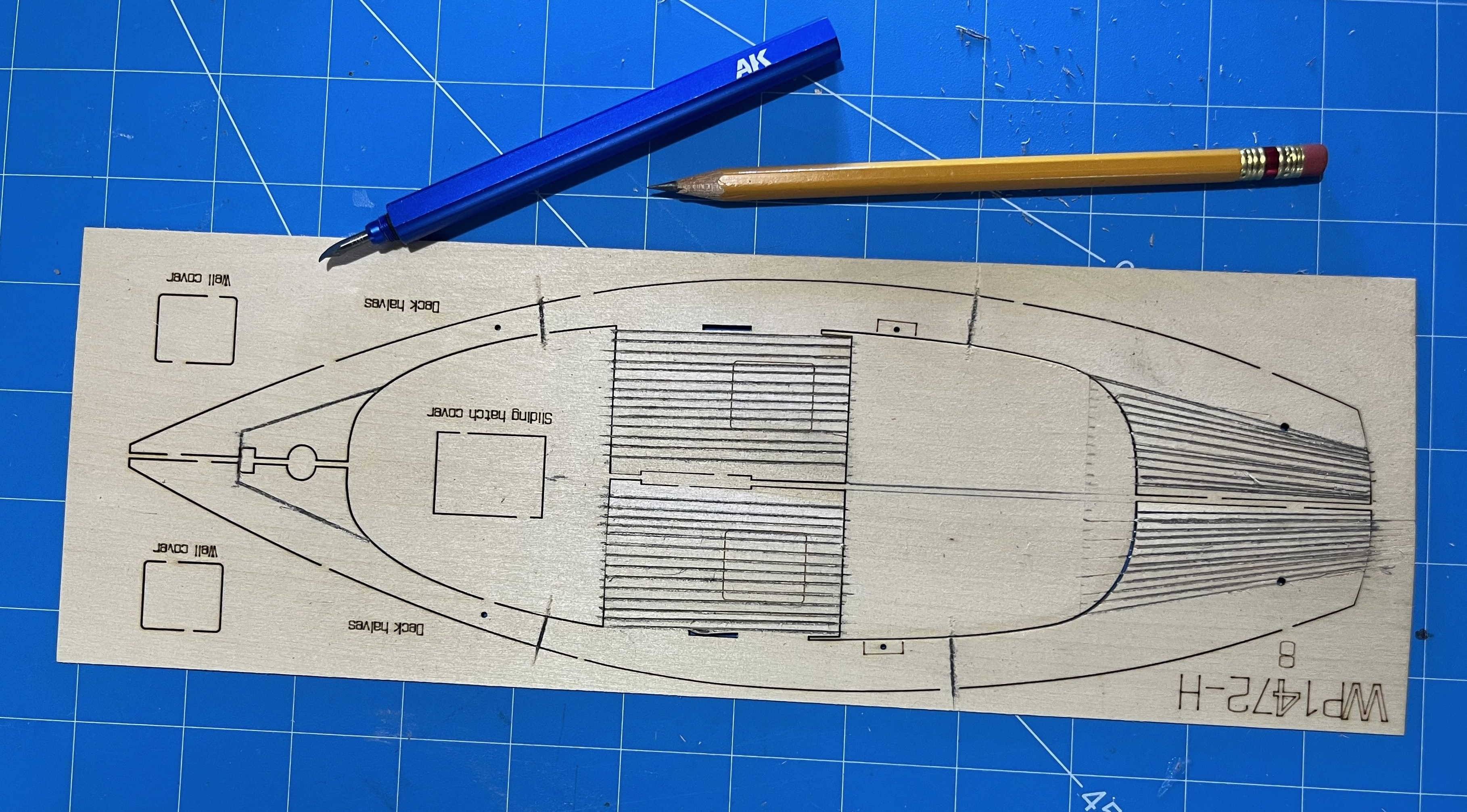
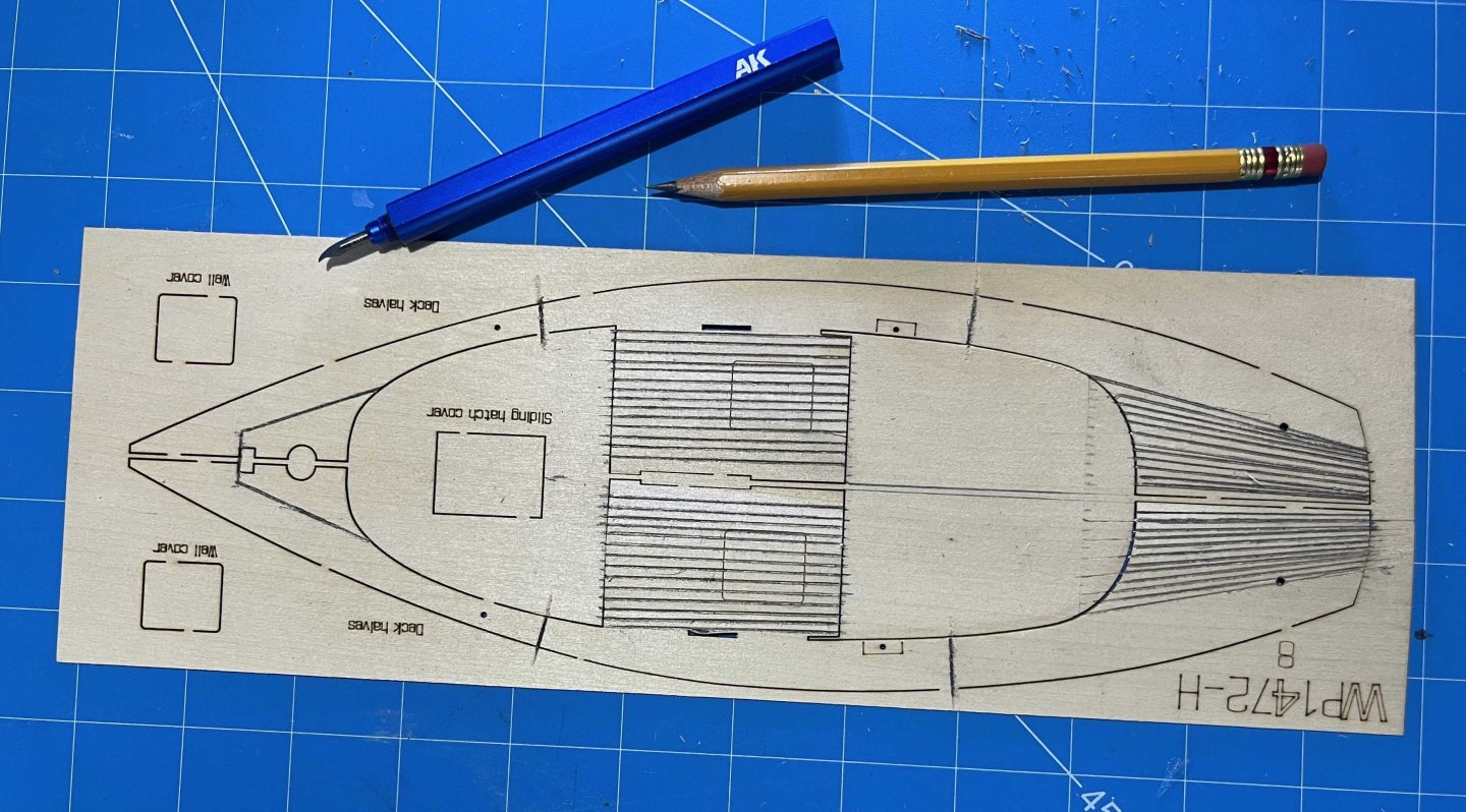
Today, I decided to skip forward a bit and prepare the sloop's deck. Plank decks leak. There's really no way around that. Back when yachts were made of real wood, not popped out of moulds, amateur sailors didn't much like drips of water on their bunks and often covered their decks in canvas. I never got to do that job and I don't recall the details. I think waterproof canvas was stretched over the deck and bedded down into a mastic of some kind. Certainly, the canvas was then painted -- painted in whatever colour the owner wished. Thus, anyone building a Muscongus Bay boat to yacht standards can paint their model's deck any which way they choose. I will give the cuddy coachroof that treatment but I doubt that a working boat's deck would have been done like that. Maybe I am wrong but I doubt that the painted canvas would stand up to the wear and tear of commercial fishing. And, once water got under it, there would be potential for serious, hidden rot. So I am going for bare wood or, more exactly, the look of scrubbed white pine that clipper captains achieved by having their crews holystone the decks. The kit's deck, however, is composed of two sheets of basswood (meeting down the centreline) and, if simply given a clear finish, would look like marine ply (though, in contrast to the cockpit floorboards, at least the visible grain would run fore-and-aft). So I'm trying for a "planked" look by scribing the "joints" between planks and blackening them with a soft pencil -- definitely a job to be done while the deck pieces are flat, not after they are on the model. But that choice, naturally, raises the question of how wide the planks should be and how they should lie. I photocopied the sheet of basswood containing the two deck pieces and played around with a pencil for a while. Howard Chapelle did not record the details of the deck of his centreboard sloop but he did give essential information on later Friendships. Importantly, their decks had narrow planks only two inches wide. I did not welcome the thought of trying to joggle many narrow planks into margin planks that followed the continuous curve of the sloop's rail. So, I have divided the deck into four zones: From the cockpit to the cuddy bulkhead, I have scribed simple, straight, 2-inch planks, aside from at the centreline, where I went for 4-inch each side, to accommodate the centreboard control-rod's slot. That's 30 planks in all. From cockpit to transom, I have imagined 24 tapered planks, 2-inch at the cockpit and 1-inch at the transom. Outboard of cockpit coaming and cuddy, I went for a single strake of very wide margin plank, made up of three (relatively straight) planks on each side. However, I'm not very happy with that and I think I will scribe an extra seam, making it two strakes per side. (Maybe I will paint the outer one.) But that had better wait until I pop the pieces out of the sheet and have the edge of the cut-out as a guide for the scriber. Rather than have a few short planks forward of the cuddy, I have gone for one near-triangular piece on each side of the centreline. With an unstayed mast (as Chapelle described the centreboard sloops), beefy mast partners would be needed, so I think I can justify the simplification. The net result, so far, looks like: It's not as neat a job as I could wish but, I hope, will give the right general impression. I'll just have wait and see how it looks once all is done, with the surface sanded and finished! Trevor
-
Steps 1 to 6 completed: All bulkheads, transom and cockpit floorboards fastened to central spine I did take a photo to prove it but my computer won't admit that that image is on my phone and I'm not about to take another. The bulkheads all went on with little trouble and some with no problems at all, just a lot of careful checking for squareness, along with judicious use of Lego blocks. The only real difficulty was squaring up #9, which goes right by the break in the spine. (And I won't try fixing that break until I have finished the fiddly work in the cockpit.) The floorboards would have been easy if not for having to make a cut-out to fit around the pump. By sheer luck, that only involved one of the scribed "boards", though I initially cut two and had to make a repair. The one cut had to be much longer than I wanted before I could work the boards in around the bulkheads. Still, I'm sure all will look OK when everything is finished (with a jib sheet loose on the boards in that area and distracting the eye from the hole, quite likely). Next up is cockpit seats and trim, then attach the part abaft the rudder stock -- and then the great adventure of adding the deck! Trevor
-
Thank you for that, JC! Nice to see that practical experience supports my deduction. (Though the fate of the 1970s reproductions isn't exactly encouraging.) I'm not surprised that Chapelle put the pump further aft in his Friendship. With more drag to the keel and lines more suited to sail (and less those of a rowing boat), the Friendship has the deepest point in her bilges nearer to the sternpost than the centreboard boats did. The best place for the pump is not literally the deepest point in the hull but the deepest that gives enough width between keelson and outer planking to fit the bottom end of the pump into. Also, for a simple elm-tree pump, the lower end has to be almost vertically under the upper, while the upper has to be where a man can work it, without it being in the way when doing things other than pumping. I'm not pretending that my version is historically accurate, just one plausible solution to a definite need for some kind if bilge-pump arrangement. Trevor
-
You continue to astound me, putting every detail into such a small scale! Trevor
- 321 replies
-
- 4
-
-

-
- Sovereign of the Seas
- Airfix
- (and 1 more)
-
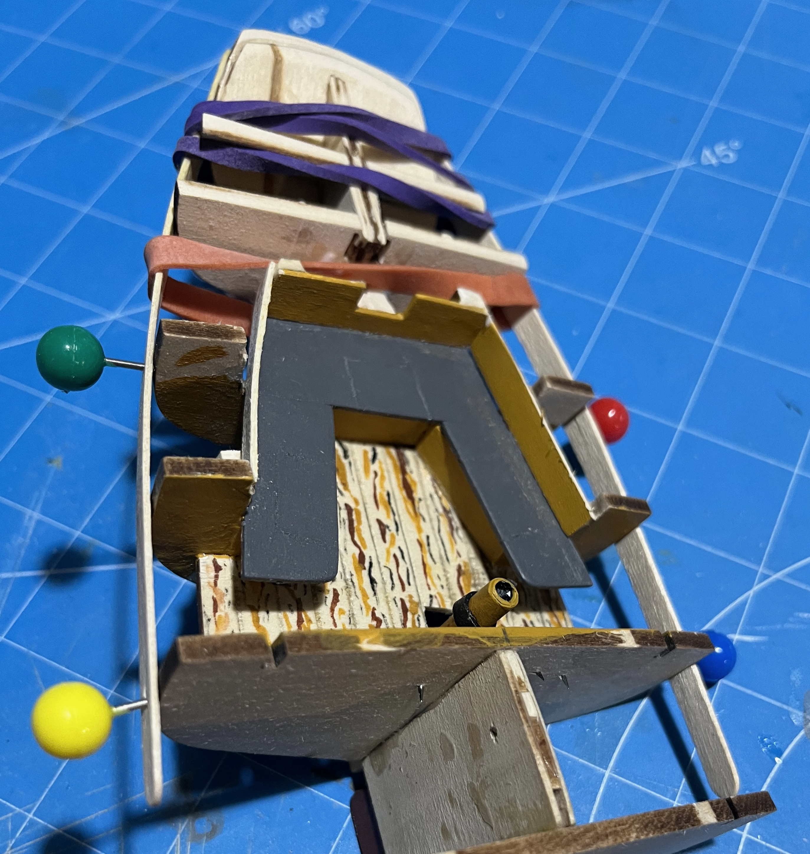
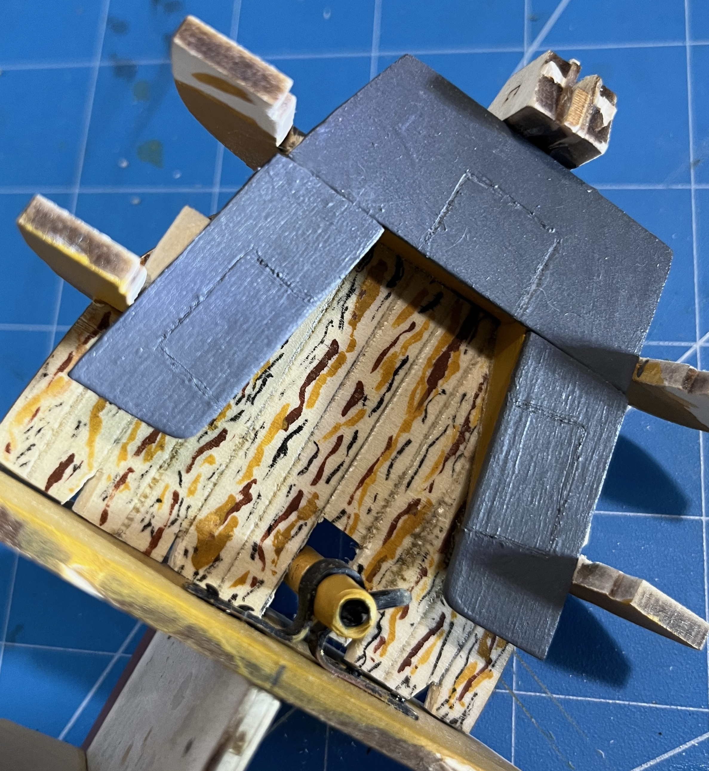
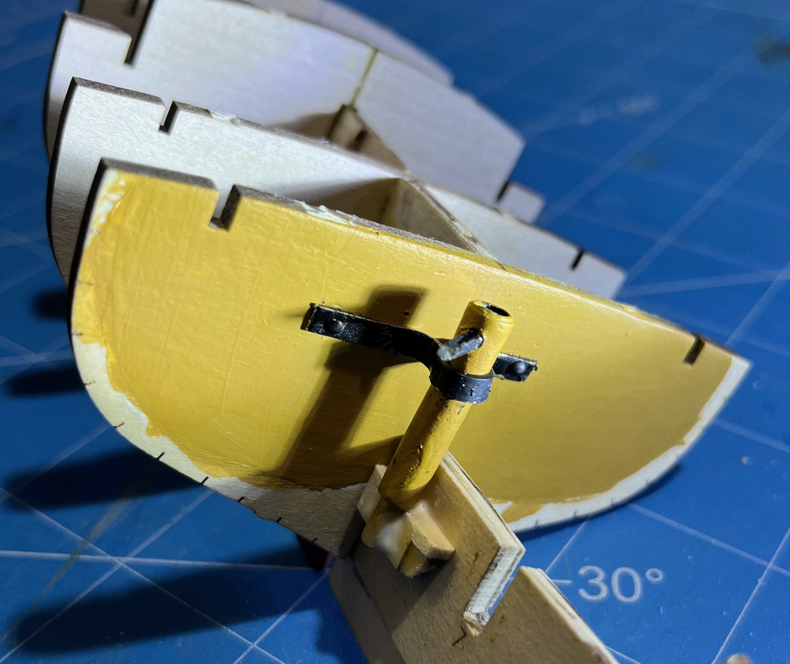
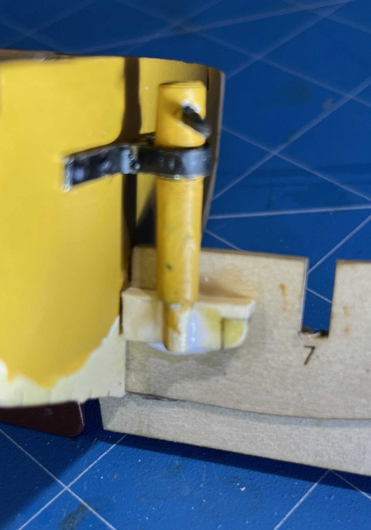
I've been back to just stolen moments for working on the smack, but that delay has given me a chance to figure out how to make artists' acrylic work for me. So I have finally got an acceptable yellow-ochre finish on bulkhead #6 and added that to the developing hull. For good measure, I worked on until I had the bilge pump installed too. So now I have: Aside from things fully sealed and solid, like paddleboards, and maybe some with a self-draining cockpit (think Laser dinghy), every watercraft needs a way to get water out of the bilges. Doubly so for planked wooden boats and ships (which always leak a bit) and triply if they are open above and so take in rain and spray too. Aboard dory or pram, you could reach to the bottom planks and use a bailer or even a sponge, but the shape of the Muscongus Bay sloop requires some kind of pump. As she is operated single-handed when lobstering, the pump really should be accessible from the cockpit, so that the lone sailor can reach it without leaving the helm for more than a moment. Since she has beach-stone ballast, there must be some kind of pump well, to separate pump from rocks. That much is certain but is out of sight and can be ignored when model building. The pump has to reach deep into the hull, lest there be a lot of water deeper still that cannot be reached and removed, so the pump needs to be at the forward end of the cockpit, not further aft. It could be set forward of bulkhead 6 but that would mean a more-complex pump well, merged into the deck planking at its top. I've opted for the simplicity of putting the pump in the cockpit itself. The big question is what sort of pump would be fitted into the well. By 1890, there may have been patent diaphragm pumps suited to a lobster sloop and certainly there were lift pumps with iron workings and pump-brake handles. But the cheapest, simplest, most familiar and perhaps most reliable option was an elm-tree pump, so that is what I have gone for. Such a pump lifts water but does not generate pressure. The discharge can only flow out under gravity. At first, I thought of making the pump tall enough that it could have a dale above the level of the cockpit coaming. That, however, would have to rise very high, so I have opted for a more-modest pump, discharging into a bucket that would then need to be emptied overside. I have assumed a pump well beneath the cockpit floorboards, then provided an "iron" loop bolted to the bulkhead, through which the pump could be lowered into its well -- or lifted out for maintenance, when needed for pumping out the live-wells etc. In model terms, the loop is annealed and bent brass, painted black. With a household nail as a centre punch and one of the bits supplied with the kit, I drilled for four nails. Those I drove with an Amati nailer -- which proved very easy after the first couple of attempts. I'm happy with it, except that shorter legs on either side would have been better. The pump body is printer paper soaked in white glue and wrapped around a dowel core. The spout is a fragment of a cocktail stick, glued into drilled hole. I shaped up a chock to hold the lower end in place, out of sight under the floorboards. When I add the assorted gear in the cockpit, I will complete the pump with its handle. And put a bucket under the spout. Bulkheads #7 and #8 should go in easily now. However, there will still be much to do in the cockpit before the deck can go on. And I have to finish the structure abaft the rudder shaft, then attach that to the rest. Trevor

-
As I seem to have touched a raw nerve and so accidentally hijacked Chris' topic, I ought to make amends -- starting with thanks to Chris, not only for providing flags in his kit but for taking the time to get them right! (Why the flags for an Admiral of the White in the kit of a frigate model, though?) Beyond that: Beauty is in the eye of the beholder, of course, so when I wrote "getting the vexillology wrong is a quick way to ruin an otherwise-excellent model", I should have added "in my eyes". (And I could also have added, along with @Kusawa2000, that the flags need to conform to the wind in the sails, however those are set, if the model shows the effects of the wind at all.) But, without detracting from the right of every model builder to show his (or her) model as they choose, I would add that flags play important roles in seagoing culture -- part tradition, part the opportunity they offer for a bit of pageantry, formerly often (and still to a degree) a means to communicate with other vessels or the shore, and maybe something deeper in the psychology of seafaring. It's an important enough topic that books are written about "flag etiquette" to help amateur sailors avoid embarrassing gaffs. There's the ensign, of course: Simple signal of the nationality of the vessel but, beyond that, a statement of pride and patriotism (and a symbol that is dipped to honour passing warships, though not by US vessels encountering USN ships for some reason). And because watercraft are inherently mobile, they get to carry their national symbol into the harbours of other nations, which brings a need for courtesy ensigns in the starboard rigging (and woe betide the yacht skipper who acknowledges the wrong host authority!). Then there's the jack and pennant that proclaim the status of a commissioned warship, company houseflags for merchant vessels, yacht-club burgees, owner's private flags, all expressing the pride of owner or ship's company. When there is cause for celebration, it is proclaimed by "dressing overall", with signal flags from bowsprit cap to masthead and all the way aft to the taffrail. And those signal flags are still used for signalling, even in the era of ubiquitous VHF radio, though primarily for signals that have to be maintained for a while: The red swallowtail of the International Code "B" for "I am loading, carrying or discharging dangerous substances" (or some such wording), seen fluttering from the radar masts of tankers as much as ammunition ships. I could go on and on. Suffice to say that, if the miniature people who might live and work aboard a model ship could speak, they would care very much about the presentation of flags. There's every reason to model just one part of a ship, such as the hull with no spars or rigging. There's every reason to include bare spars, all neatly squared but without sails, the running rigging simplified and no flags at all. But if you aim to show a vessel as she would be in use, the flags need to be there and need to be the right ones in the right places. Or else your model is going to look wrong, in the eyes of those who know! Trevor
-
I do. Every time. Sailing warships carried such large and prominent flags that they form a key aspect of the overall appearance. So getting the vexillology wrong is a quick way to ruin an otherwise-excellent model. Trevor