
Kenchington
-
Posts
679 -
Joined
-
Last visited
Content Type
Profiles
Forums
Gallery
Events
Everything posted by Kenchington
-
 I fully endorse the recommendation of "Yogi" Jensen's book: An essential source for anyone trying for a realistic model of Bluenose II and very valuable to anyone aiming for the original racing fisherman. Not really of any concern to model builders but the hull currently afloat might better be called Bluenose III or even Bluenose IV. The original was, of course, built in 1921 and lost in 1946. Bluenose II (a very close replica, built in the same yard and by some of the same men) was launched in 1963. Softwood fishing schooners were not built to last and, by the mid-1990s, she was in bad shape. Then the 1995 annual G7 heads-of-government meeting came to Canada and specifically to Halifax. That freed up federal money and she was given what, in earlier times, might have been called a "great repair", with much of her structure replaced -- as a backdrop for photo-ops with assorted presidents. We don't have high-quality politicians in Nova Scotia and the Minister then responsible insisted that the new wood used in the repair be the same types as the old. (Bad idea.) In those days, I had a friend who was a naval architect and marine surveyor. He was involved in the rebuild project and tried to save a treenail or two for me but the same Minister insisted that everything go through a chipper, to ensure that nobody could own a piece of the 1963 hull -- not even the Nova Scotians who supposedly collectively own the entire schooner through our government. (Another bad idea.) Whether you call what emerged in 1995 a rebuilt Bluenose II or Bluenose III is up to you. The Provincial government chose the former. By 2011, she was in bad shape again and went back to Lunenburg for a complete rebuild. That time, she was given a more robust structure and more resilient types of timber -- apparently considerably changed internally with little (if any) of her original material retained, though her external appearance is unaffected. By rights, the new vessel which emerged should have been Bluenose III (if not IV) but thereby hung another tale: It turned out that the Roué family (heirs to the original designer) still held rights to the design. If certain arrogant individuals had asked nicely, I don't doubt that permission would have been granted to build from the original plans, as it had been in 1963. Maybe some nominal royalty could have been paid. But arrogance won out over common decency and, to conceal the reality that a new hull had been built to an old design, the fiction has been maintained that what emerged in 2013 was a repaired Bluenose II. Trevor
 -
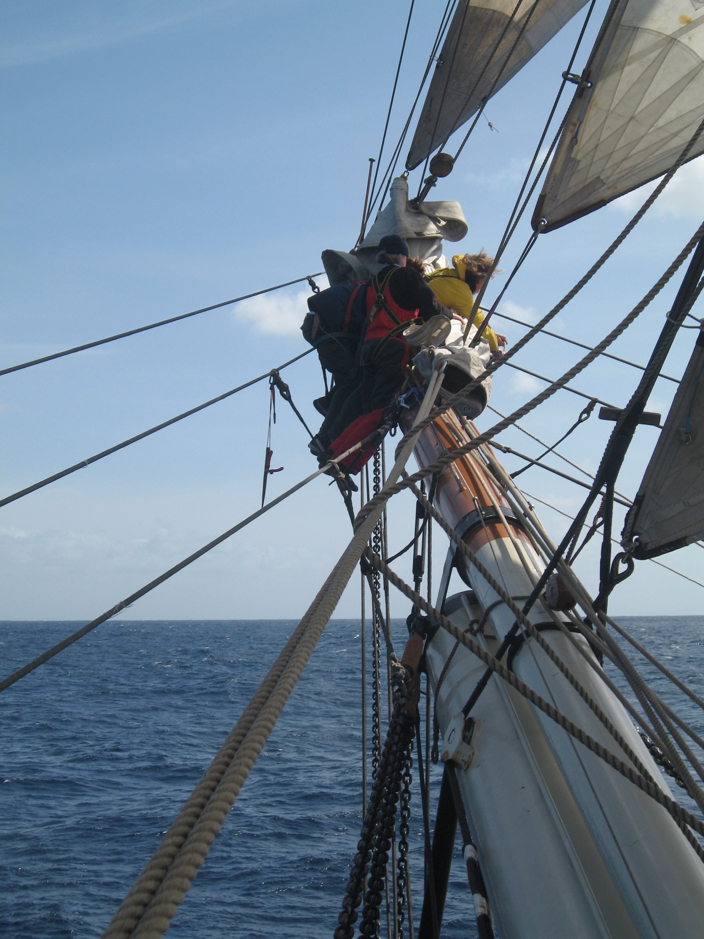
Hi @bnw, I thought that overhead photo would be useful for anyone building a model of Bluenose II. I'm glad you like it. I have seen the schooner a great many times, especially back when she spent summers in Halifax and I lived in the city. I have been aboard her under sail for a couple of her tourist trips around the harbour, though not for many years now, and have been on the water near her other times. The best view I had of her, however, came during a short sail from Halifax to Lunenburg in the Rose. Our captain was a bit concerned at the weather forecast and sent us aloft to the fore topsail yard to practice reefing. While up there, a very sweet-looking, small (as I thought) schooner came sailing past, heeled far over. It was only as she passed, almost below where I stood, that I realized she was Bluenose II. A memorable moment! Trevor
-
Looks like you are off to a great start! You have said that you aim for a model that looks nice, rather than a miniature replica, but the appearance of the prototype is a good starting point for your decisions. To that end, the schooner's own website has a useful photograph taken from directly overhead, which shows her deck very clearly. I won't infringe on copyright but you can find the image at: https://bluenose.novascotia.ca/node/122 That photo was taken during an annual fitting-out and has much of the schooner's gear (and much of her crew!) laid out on the wharf alongside, so a very useful reference as you proceed. Trevor
-
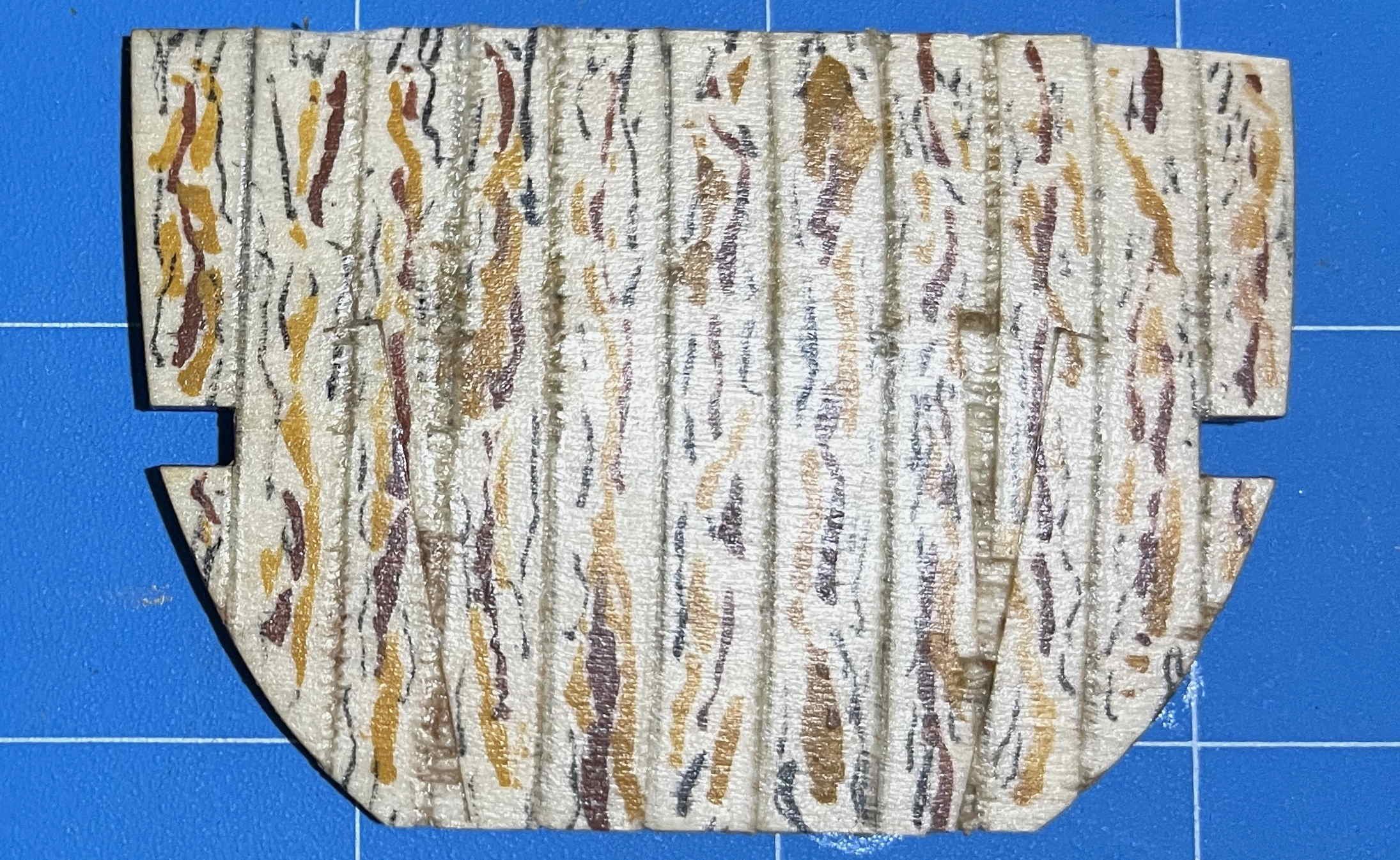
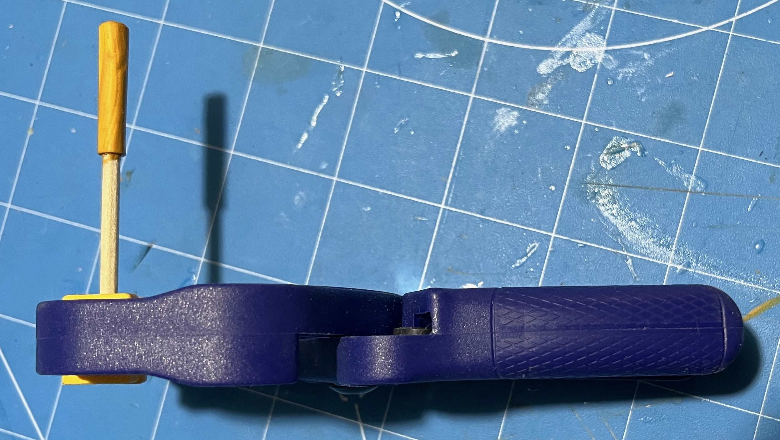
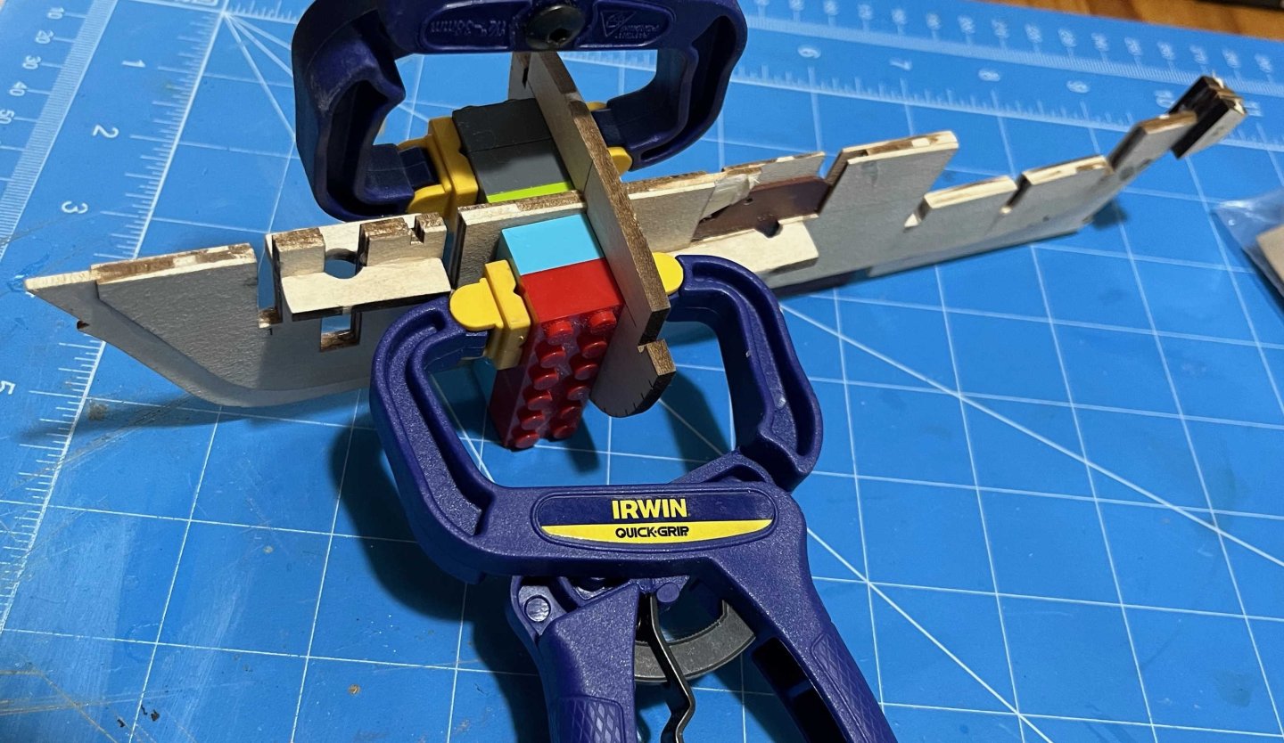
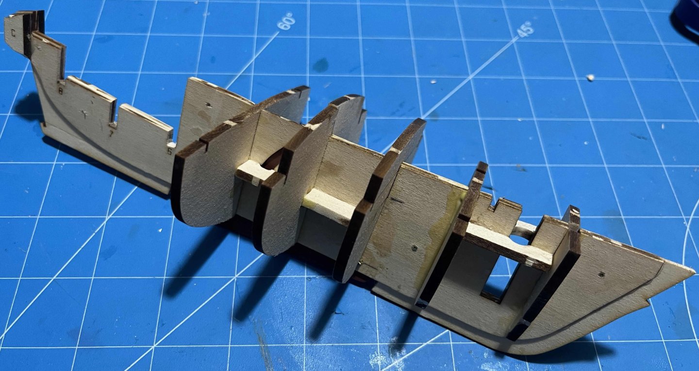
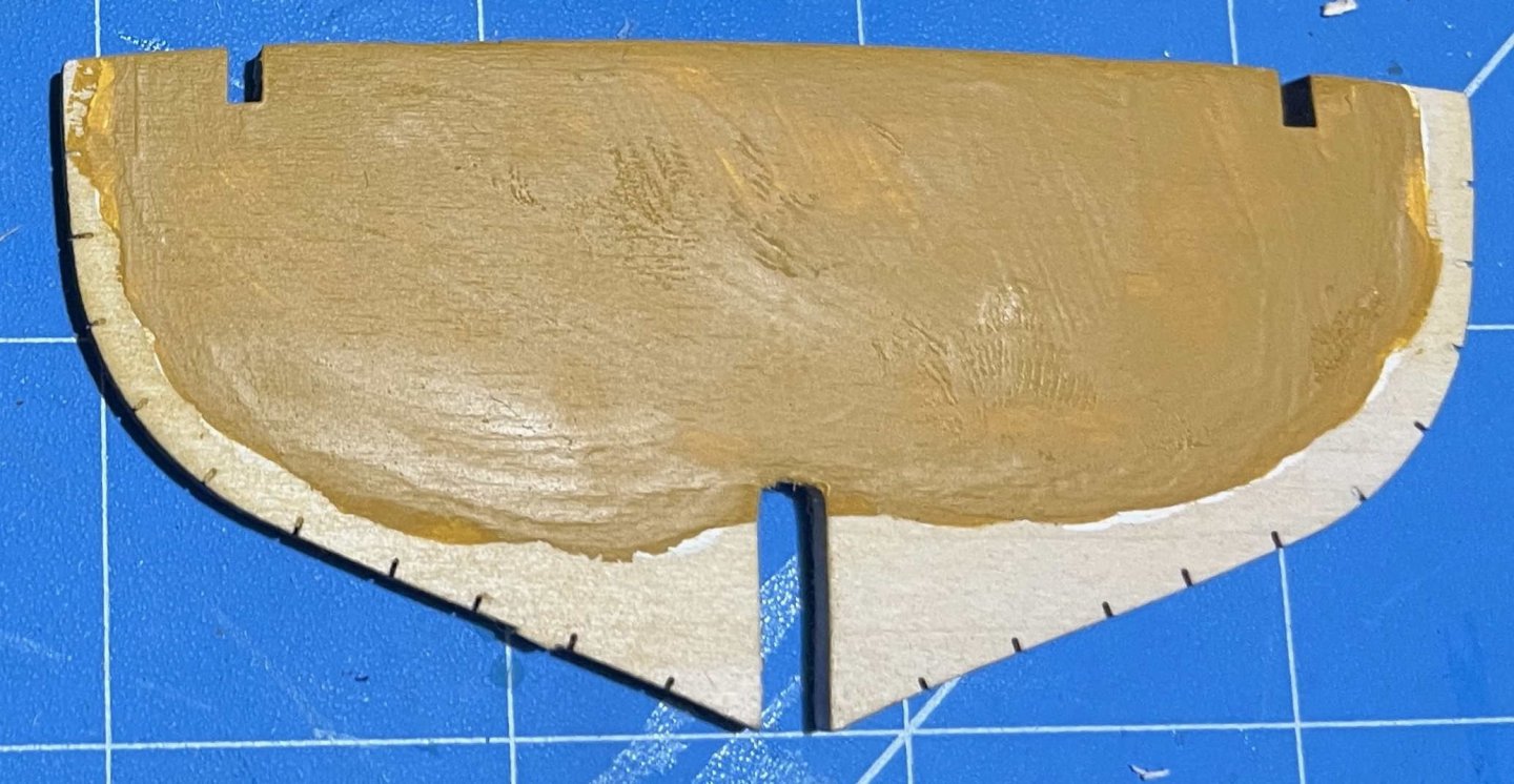
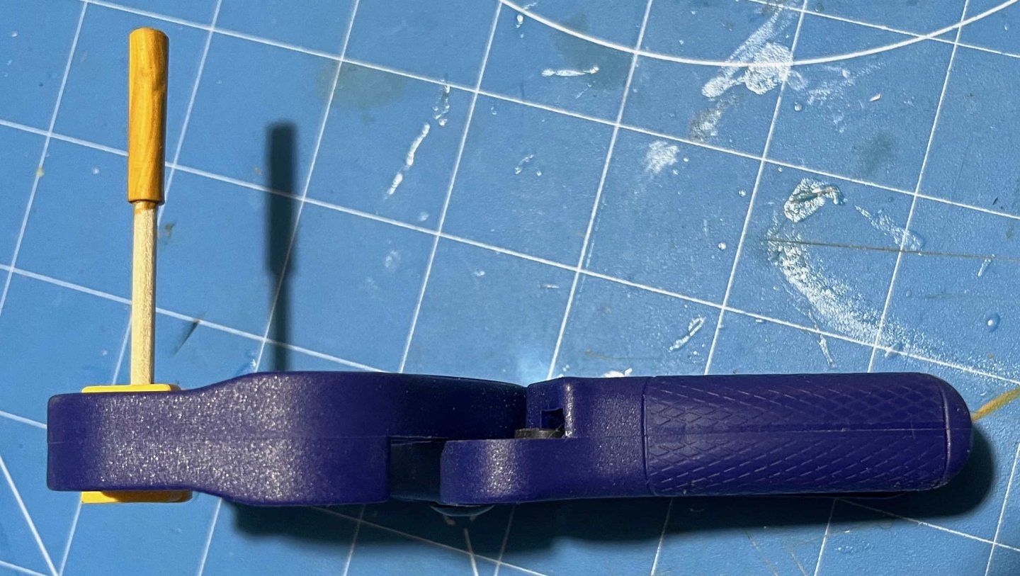
After a week with only stolen moments for model building, I have had most of a rainy Sunday with the sloop-to-be. The odd moments had been enough to strike centrelines across each bulkhead, free it from its sheet, flip it over and reinsert into the sheet to check symmetry. No problems there at all. Fitting bulkheads to spine has been more challenging. Before removing charr, they were all much too tight to go into place. Once the charr was off, most were a little too mobile. Meanwhile, the irregularities in my fitting of reinforcing pieces to the spine meant that each bulkhead needed individual fitting. No big problems, though. The instructions recommend fitting bulkhead 4 first. That, however, is in two halves to make space for the centreboard, so I decided to begin gluing with #3 to get something more solid to establish perpendiculars and have a reference to take check measurements from for the other bulkheads. There are three dimensions, of course. The vertical fit is mostly easy, as all but two bulkheads should be flush with the top of the spine. The exceptions are #3 and #4, which rise up to support the cuddy's coachroof. #4 has steps where the halves close over the spine but #3 needed aligning. I dry-fit #1 and #2, then checked the heights of the outer ends of the three bulkheads, where they will support the deck edge, and adjusted #3 until the alignment was within the range to perfect by sanding. To get the other two dimensions perpendicular, I marked a horizontal line across the bulkhead and clamped on trusty Lego blocks, aligned so as to keep everything tight and square. Then lifted the combination off, applied glue, replaced it and it just needed finger pressure until the glue began to bite: The other bulkheads needed varied fiddling, with the Lego arranged as and when needed -- #1 going into place with fingers only. That's got me to: While waiting on glue to harden up, I started preparations for the cockpit and its detailing. Bulkhead 6 forms the forward edge and (unlike anything yet in the model, aside from the centreboard) it will be visible when all is finished. Hence, I am trying to paint it before attaching to the spine. Chosen colour is yellow ochre, that being an available and affordable option for a lobster fisherman circa 1890. Unfortunately, even when primed, a first coat well sanded and the second with the paint thinned, artist's acrylic still shows the brush strokes: Further trials needed! The kit's cockpit "floor" would be OK if painted in an opaque finish, but that would not be realistic. In a clear finish, past build logs show that it looks as though made of marine ply -- again, not realistic. Tracing plank "edges" across the surface doesn't fix the problems as the grain of the underlying basswood runs athwartships. My solution began by scribing "gaps" between "boards" (1/4 inch wide, or 6" full-size: Narrower would have been better but more work.) Ideally, I would have cut right through and set the "boards" apart from one another but I didn't fancy getting caught on the extra complications. To hide the reality that the grain of the wood runs the other way, I doodled in some new "grain", using two colours of acrylic (intended for leather, hence suited to absorbent material) and thin lines of India ink, then topped everything off with two coats of ModelExpo clear finish. The result is ugly to look at and I should have been less enthusiastic with the "grain". However, once the cockpit is finished, this version may pass for bare spruce boards with the resin still oozing out: At least nobody will mistake it for a sheet of marine ply! I have also started building an elm-tree pump to go in the cockpit beside the forward bulkhead. It is a short piece of 1/16 dowel, with heavy printer paper soaked in white glue and wrapped around, then given a coat of yellow ochre to match the rest of the cockpit furniture: The paper extends beyond the dowel and the hollow interior will become black. It will still need a handle and a spout, while I will need a pail for the water to pour into. (I decided against a much taller pump that would have discharged over the cockpit coaming.) And that's it for today! Trevor

-
Phil, You asked: To my regret, I cannot remember how we did it aboard Stad Amsterdam. Looking at the photos from this trip, she didn't have many spare belaying pins, so it wasn't a matter of there being designated, regular belaying points for the stuns'l gear. Maybe the buntlines of other sails (which are slack, when the sails are set) were shifted and tied off loosely somewhere. Two lines on the same pin might be a necessity sometimes but I'd not want to do that if I didn't have to. Maybe if the second line was much lighter (so it could fit on the pin), under much less load (so that it wouldn't dig into the first line, damaging it and jambing at the same time), and if I was certain that I would have to loose the second line before there was any need to adjust the first one. But not ideal even then. Trevor
-
Phil: I thought I remembered that Marquart was of German origin but did not want to say so here as I could not confirm. He may have translated everything into German, at least in his head, then into English for publication. Occasional errors in technical usage should not be unexpected. George: Good of you to catch Steel's use of "spread yard"! That may well be where Marquart found the term and so I have to accept that it was sometimes used as an alternative for "crossjack", at least in relation to fore-and-aft rigs with square topsails. (Naval cutters as much as schooners, perhaps?) My only copy of Steel's Masting and Rigging is a 1983 printing of a 1932 edition, which did not claim to be complete. It does have, amongst much other tabulated data, the spar dimensions for a schooner of 110t in the merchant service -- which may be the same entry that you found. That has the main tops'l yard at 38ft 6in and the "Spread Yard" at 47ft 7in, while those on the foremast are 30ft 6.5in and 40ft 7in. The "Square Sail Yd." is given as 38ft 7.5in. It is listed with the spars of the mainmast but the squaresail would have to be set on the fore, if it was to do its job without interfering with anything else. I don't see the "Spread Yard" term used with other rigs, nor "crossjack" used for the schooner. My reading of that is that Steel's "spread yard" is what everyone else calls a "crossjack", while his "squaresail yard" is the spar to which the head of the squaresail is bent -- in his case the entire length of the head. As to your other sources: "Lower yard" can be nothing more than an alternative for (rarely seen) "course yard" -- more often called the "fore yard" or "main yard", as appropriate. "Crossjack" was originally the yard-with-no-sail that spread the food of a topsail above a lateen mizzen. Once gaff drivers and spankers replaced the old mizzens, a sail could be set from the crossjack. Rather than re-naming it as a "mizzen course", it took its name from the yard and so became the "crossjack" (normally pronounced "cro'jick"). That got weirder still on the four-masted barques, where the third (mizzen) mast was a duplicate of the fore and main but had a cro'jick rather than a course! So do not assume that crossjack yards never had sails bent to them. But, in topsail and topgallant schooners, there were yards-without-sails on at least the foremast and sometimes the main also, called "spread yards" by Steel but "crossjacks" by other sources, while the squaresails sometimes hoisted to those yards could have their heads bent to "squaresail yards", either full-length or as short clubs in the centre. Make sense? Trevor
-
You have induced me to pull Marquardt's book off the shelf, maybe for the first time since I read it. (I was not impressed and have not bothered with it since.) So I now see where you got your terminology from, though I'm left to wonder where he got it. I can't say that it was never used by the men who sailed under such rigs, though I wonder whether multiple translations from several European languages did not lead to confusion. I have taken a look at Brady's Kedge Anchor, in case USN usage was different, but he does not have a "spread yard" either. He does tabulate the spars of a naval schooner, including a fore yard 50ft long and a "Yard for Square-sail" at 22ft 8in. I'll take a guess that that had the middle two quarters of the sail bent to it, while the outer corners of the head of the sail were hoisted to the arms of the fore yard. Trevor
-
A crossjack is usually understood as a square yard with no sail bent to it. ("Cross"=square, "jack"=useless, hence the yard that spread the foot of a mizzen topsail, above a lateen mizzen, was a "purposeless" yard since it carried no sail.) Thus, what Marquardt meant by "crossjack" was probably what you are calling a "spreadyard". I suspect that he meant that a schooner's squaresail (not really a course) was hoisted to the crossjack by three or four halliards, without its head being bent to any spar (unless there was a short, light one in the middle). I would expect the stuns'ls to be bent to their yards, which would be hoisted with the sail when required. Stuns'l booms would, as you say, usually remain aloft and hence on the yard there. My one experience helping set a stuns'l at sea, there was a whole lot of work, taking blocks aloft for attachment to booms and yards, then reeving halliards, sheets and whatever, all before any canvas could leave the deck. When not playing with those flying kites, the only visible evidence of their existence were the booms, so that simplified appearance would be fully justified in a model. Then again, if the stuns'ls were in frequent use, their gear would likely be left rigged, even when the sails themselves were sent down. So you would be equally justified in showing everything! Trevor
-
Bower anchor project by Sizzolo
Kenchington replied to Sizzolo's topic in - Build logs for subjects built 1751 - 1800
I saw that your quotes said "bent" and wondered whether former usage was less specific, so that "bent" might mean "attached" and so included a splice. However, on reflection I suspect that there was a desire to separate the buoyrope from the buoy, making stowage simpler. Hence, an attachment that could be tied and untied would be preferable. And I am sure you are right that there was more than one way to do it. As was said during the last decades of commercial sail: "Different ships, different long splices". Trevor -
That's something that I had never even heard of! Thank you, Harvey: I will have to try for a library copy somewhere as it does not seem to be available on-line. Trevor
-
That's a wonderful explanation, @wefalck! I dare say that I will come back to this question from time to time but my immediate interest is circa 1890. However, it is also on Down-East Maine, which may then have been a generation behind developments in the cities of the USA. (Nova Scotia was at least that far behind.) I think I am safe ground with the earth pigments. Green might be another option but that was forbidden on fishing boats in some areas, as being unlucky. I can't say whether lobstermen in Maine shared that superstition but I don't have to justify not using a particular colour. Trevor
-
Spare yards on 19. century ship?
Kenchington replied to RolandR's topic in Masting, rigging and sails
Spare spars would not be stowed in the hold: Far too difficult to get them down there. They were usually stowed wherever the boats were, whether on deck or on beams above. Trevoe -
Bower anchor project by Sizzolo
Kenchington replied to Sizzolo's topic in - Build logs for subjects built 1751 - 1800
The wall knot is Ashley's #671 (though he features it in multiple other places in his compendium), while a double-wall is his #675. basically, having formed a wall knot, each strand is taken under two others and over one, paralleling the strand that it ends beside in the initial wall knot. Ashley's drawing is far easier to understand than my words! Trevor -
Bower anchor project by Sizzolo
Kenchington replied to Sizzolo's topic in - Build logs for subjects built 1751 - 1800
"Well done" is an understatement: I have never even managed a proper wall knot at 1:1 !!! -
From the shipyard to the Richmond wharfs, yes, but not so much the area I knew, from Historic Properties southwards. The bulk of Citadel Hill sheltered everything beyond. One of my wife's relatives (aunt or uncle, I think) was in the South End at the time and came through without harm, unlike so many further north. But, getting back to "Bonny": There was a time when I had teenage dreams of flying Phantoms off Ark Royal. Now, I look at those images of Trackers and I can't wrap my mind around the idea of operating heavy aircraft off the top of a ship at sea! It's extraordinary that it can be done aboard USN's 90,000 ton carriers but with one of the RN's "light-fleets"? Impossible! And yet it was done. Trevor
-
And a good suggestion, JC! A quick look at Winslow Homer's paintings (about right for time and place, for my Muscongus Bay sloop) doesn't show much beyond the colours available a century before. He did add some rather muted blue and, in at least one painting, dashes of brighter blue and red. The sloop's topsides must be white (confirmed by multiple black-and-white photos). It's looking like the trim will be black, red ochre or a combination of those. Larger inboard surfaces maybe yellow ochre and/or neutral grey (supposedly from mixed white lead and lampblack paints -- though actually from a bottle of grey!). That will be muted and somber but probably realistic. Trevor
-
I arrived in 1977 (as a student), just in time to see a little of what had been there before the Waterfront Destruction (sorry: "Development") Commission tore down the last of the old archways that had led off Water Street. All long gone by 1993, by which time a working waterfront had become a recreational area. I've lived in Bristol and Hobart, as well as Halifax. I've even had a chance to see something of London, Buenos Aires, Boston and others. Each city was faced with redeveloping a port area after the box boats replaced break-bulk freighters. Each found a different solution, though in my experience only Halifax simply bulldozed almost all that was there before. Then again, amongst the port cities I have known, only Halifax started with a run-down, all-wooden waterfront. And Bristol could have been worse: The city Council planned to bridge over the entire Floating Harbour, keeping an underground water basin for flood-control only! Fortunately, money ran out and then the tourism value of site emerged. So that silly plan was scrubbed. Trevor
-
Bower anchor project by Sizzolo
Kenchington replied to Sizzolo's topic in - Build logs for subjects built 1751 - 1800
That sounds like one of those impossible Chinese wooden puzzles 😀 -
Does anyone know of a source for information on the range of colours (cheaply) available in marine paints by the end of the 19th Century? I'm not after the colour of antifouling, which was the familiar red shade that long remained in use. Nor am I after the variety of colours that could be used in interiors, nor even those that (at great expense) could pick out details of a warship's carvings. My present interest is in the paint that a fisherman might apply to the topsides and other above-water, exterior surfaces of his boat. And I am after paint colours, not oiling of bare wood. For the later 18th Century (and passing over colours that don't fit my criteria), Jean Boudriot lists only white (a creamy off-white, based on white lead), black (based on lamp black), red ochre and yellow ochre. A hundred years later, English fishing boats could be finished in "black varnish" (which wasn't what we would now call a varnish), while green seems to have been popular in some areas (though rejected as "unlucky" elsewhere!). The early 20th Century brought a much wider variety of pigments, of course. I'm just after some authoritative source on what might have been affordable circa 1875--1900. Trevor
-
Bower anchor project by Sizzolo
Kenchington replied to Sizzolo's topic in - Build logs for subjects built 1751 - 1800
I would need to see more of his text, to get the context. However, my first reading of what you have quoted would be that the eye at one end of the buoy was left as a "soft eye" (meaning only rope) and used when fishing the buoy out of the water, then lashing it down aboard ship. The other end of the buoy would have had two interlinked thimbles, giving metal-to-metal contact when there was tension on the buoyrope. One of those two was held in place by seizing the ropes that pass around the buoy, thus forming a "hard eye". The second thimble was available for the buoyrope to be spliced around, when the work reached that stage. Conventional, teardrop-shaped thimbles are slightly open at the narrow end. It isn't easy to work one into the other, to interlink them, but it can be done if neither thimble yet has any rope passed around. Trevor -
Getting Started: From Dollhouses to the USS Constitution
Kenchington replied to Jasennord's topic in New member Introductions
Welcome aboard, Jasen! I'm only two steps ahead of you on our shared journey but I think you have chosen an excellent path with the Model Shipways combo. Trevor -
The latest to begin the Model Shipways 3 kit set
Kenchington replied to Taken Aback's topic in New member Introductions
Welcome aboard, Brian! Thanks for your kind comment on my pram build log. I hope it does prove useful once you have your dory finished! Trevor -
It's a bit more complicated than that. The Medieval Basques probably started out hunting Atlantic grey whales and those are long gone now. The only reason they are not gone as a species is that available data suggest that they were always the same species as the Pacific grey. That too was very nearly hunted to extinction but (thanks to the good people of the Californias, both Baja and Alta, plus their more-northern neighbours) the Pacific grey has been pulled back from the brink. There has been study of the whales that the Basques hunted on the coast of Labrador, through examination of bones and the like. I'm not up to date on the conclusions but there was some suggestion that it was bowhead, rather than right whales. There are no bowhead anywhere nearby now, though that might be an effect of climate change, rather than hunting. As for the North Atlantic right whale: With less than 400 surviving, its future is far from assured -- though we are now making major efforts to eliminate anthropogenic losses. My worry is that past hunting narrowed the genetic base so far that the whales will be vulnerable to some viral epizootic. I really, really hope not but when the numbers of a large mammal drop below 10,000, even 100,000, the odds are not good. Below 1,000 may be too low for any hope to remain. Still, we must try! As for other species: Despite a lot of alarmist pronouncements, not one species of the open-sea (meaning a species that can complete its lifecycle without approaching land) is known to have gone extinct through the centuries when humans might have been involved. Not one. We have messed with their populations, upended ecosystems and generally caused mayhem. But the way that humans interact with the seas is fundamentally different to what we do on land and, thus far, knocking out the last individuals of open-sea species seems to be beyond us. Fortunately. Trevor P.S.: I was going to mark this post as "No Modelling Content" but I think we need to understand the context of the ships that we model. So, for anyone building a whaleboat kit, this is relevant information.
-
As the cockpit has to be completed soon, I've been thinking about essential gear. There's a bunch of modern safety equipment, like flares and lifejackets, that no commercial fishermen would have even considered in the 19th century (nor for much of the 20th either). Then there are things that our little sloop would very likely have had on board but stowed away safely in the cuddy, like a box compass, lead and line, fog horn (lung powered) and a hurricane lantern. Beyond the hull itself and the rig (and leaving aside the lobster traps, buoys and buoy ropes for now), I can only think of four things that ought to be aboard and visible: 1: A pair of oars, for when the wind falls light. (The kit has the rowlocks but not the oars to go with them.) 2: A boathook, for picking up the mooring at the end of the day-- or, more likely, a gaff for catching the lobster buoys which could double as a boathook. 3: An anchor, with some chain, for when there is no other way to keep from being blown onto a lee shore. 4: A bilge pump, for clearing all the water that gets into the cockpit and thence down to the ballast. Oars will need to be lashed down on deck, as there is no other space long enough for them. Gaff would go there too, unless shown in use. I think that the anchor needs to go in a corner of the cockpit. Setting or weighing it would mean going forward to the bow but the deck there is narrow and dangerous, so I'd guess that a lobsterman would range a sufficient length of warp in the cockpit, carry a bight of it forward (outboard of all obstacles), belay that to the sampson post, pass the anchor's side of the warp through the bow fairlead, then retreat to the cockpit before actually dropping the anchor. The bilge pump is a big unknown. Chapelle's draught of a Friendship sloop shows something that looks like an old-style pump, rising from beside the keelson, with what might be a pump dale at the level of the coaming. I'm thinking of trying to replicate the visible, upper part of that. Any thoughts and comments would be welcome! Trevor
-
Step 2: Centreboard: Completed I had a fight to get a tiny piece of 1/16 brass rod into place as the pivot for the board, gooped some epoxy over the ends to hold it in place, laid the spine down and the ***!!!!## piece fell out under gravity alone! So I shoved the whole length of kit-supplied 1/16 through, added epoxy to one end, then clipped off most of the rod with shears. That worked. Control rod shaped up nicely and easily. I painted as much as might be visible in black, rather than have shiny brass on a fishing boat. Looked nice for a while until the paint started chipping off. I dare say it will be fine after a touch-up. Still have the wooden handle to add but the instructions say "later" -- presumably meaning after the deck is in place. Step 4: Reinforcing pieces: Completed but badly There's no warning in the instructions that the reinforcing abreast of the centreboard trunk may obstruct the movement of the board's control rod. Mine did and I had to gouge grooves before gluing, then widen the grooves after. My bigger problem is that I can't see the laster-marked position lines once glue starts oozing out of the joint. For most of these pieces, a little bit of displacement hardly matters but I'm going to have to do some surgery to get Frame 4 to fit. Still, that shouldn't be a problem. Feels strange to be assembling the various parts without a care in the world, knowing that everything can be sanded or shimmed as necessary, then hidden later. With the dory and the pram, precision in the initial structure was critical and yet every piece is visible in the finished model. Trevor