
Kenchington
-
Posts
662 -
Joined
-
Last visited
Content Type
Profiles
Forums
Gallery
Events
Everything posted by Kenchington
-
 I do not intend to log my build of the Muscongus Bay boat in the same detail as I did with the Norwegian pram. For one thing, there are MSW members who know the full-size boats, or at least the Friendship sloops which evolved from the centreboard boats, whereas I have never even seen an example of either type. So I won't have much to offer that would be unique. Still, I figured I should open a new log, so that I can post whatever comes up. Right now, I'm just scanning previous build logs and preparing notes to supplement the kit instructions! Trevor
 -
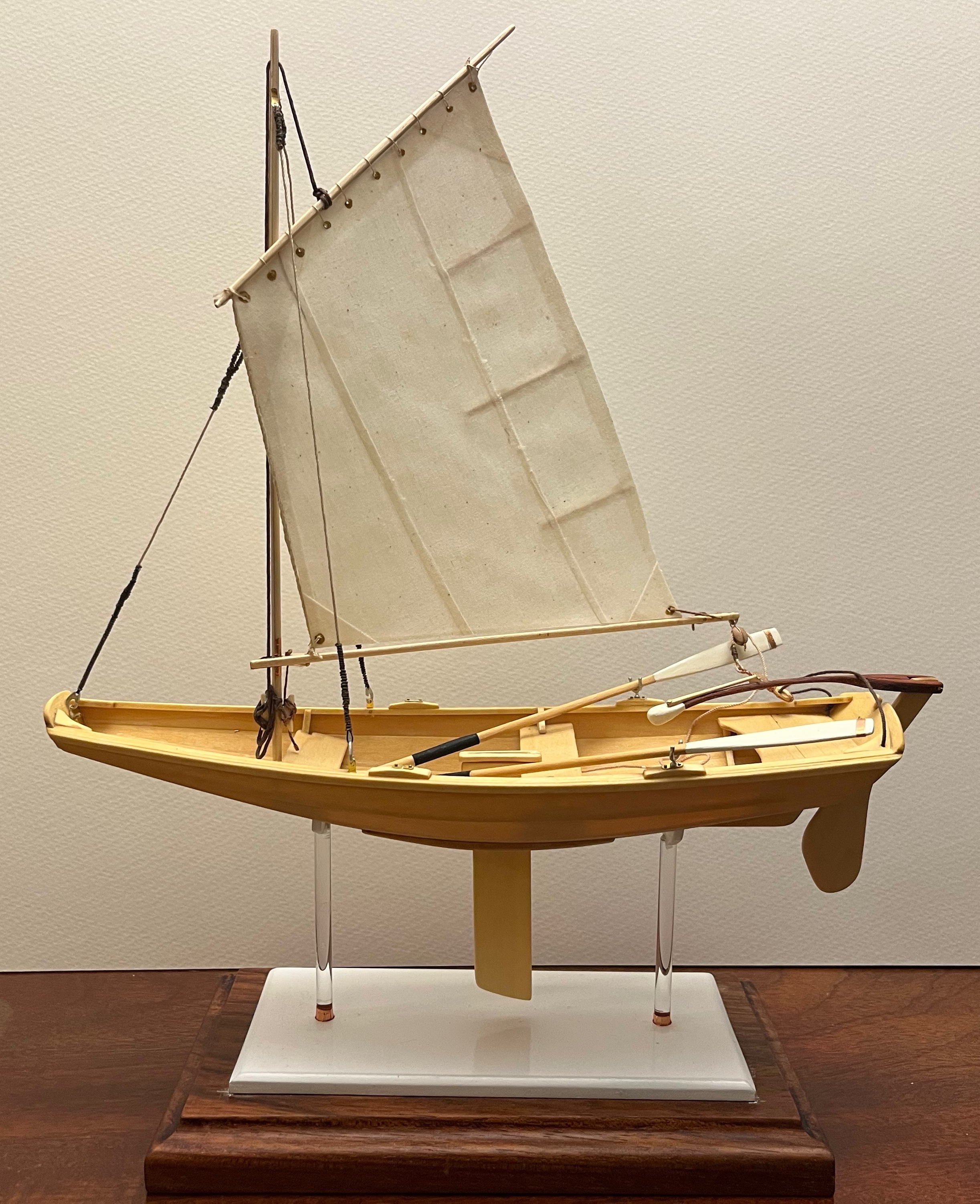
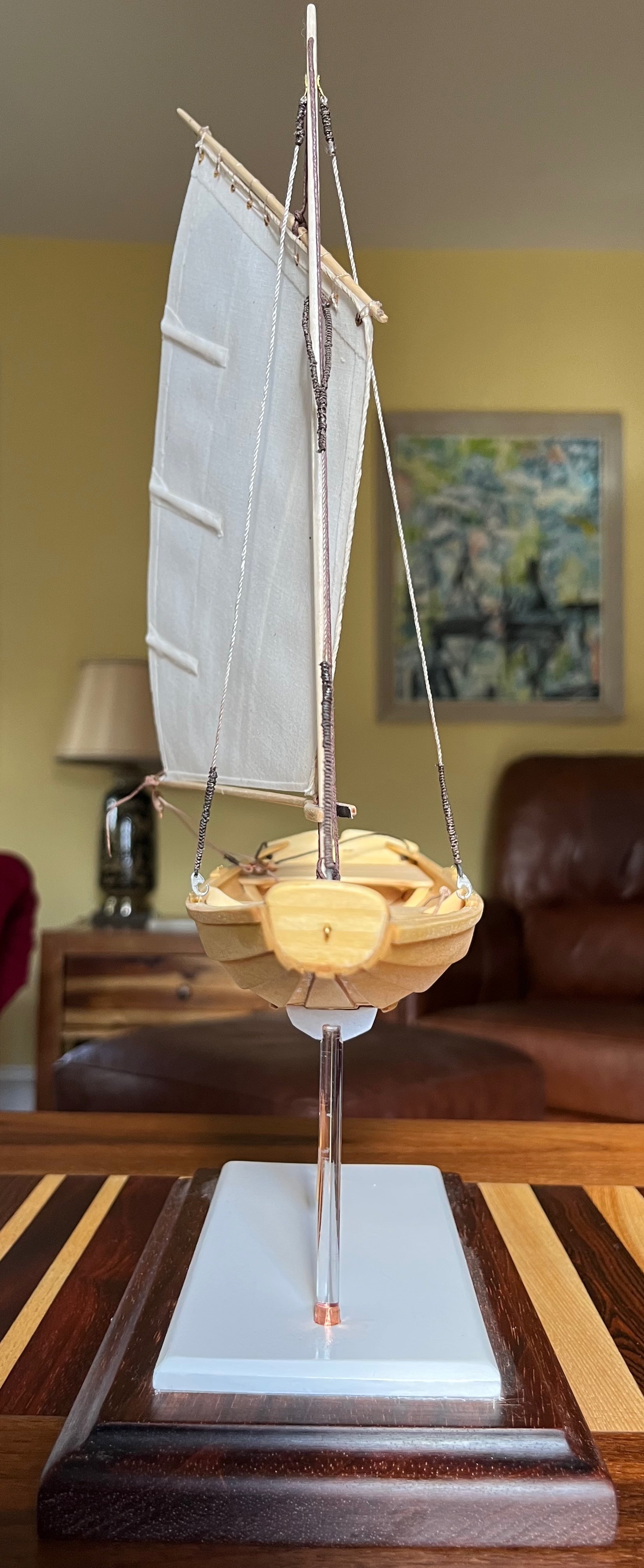
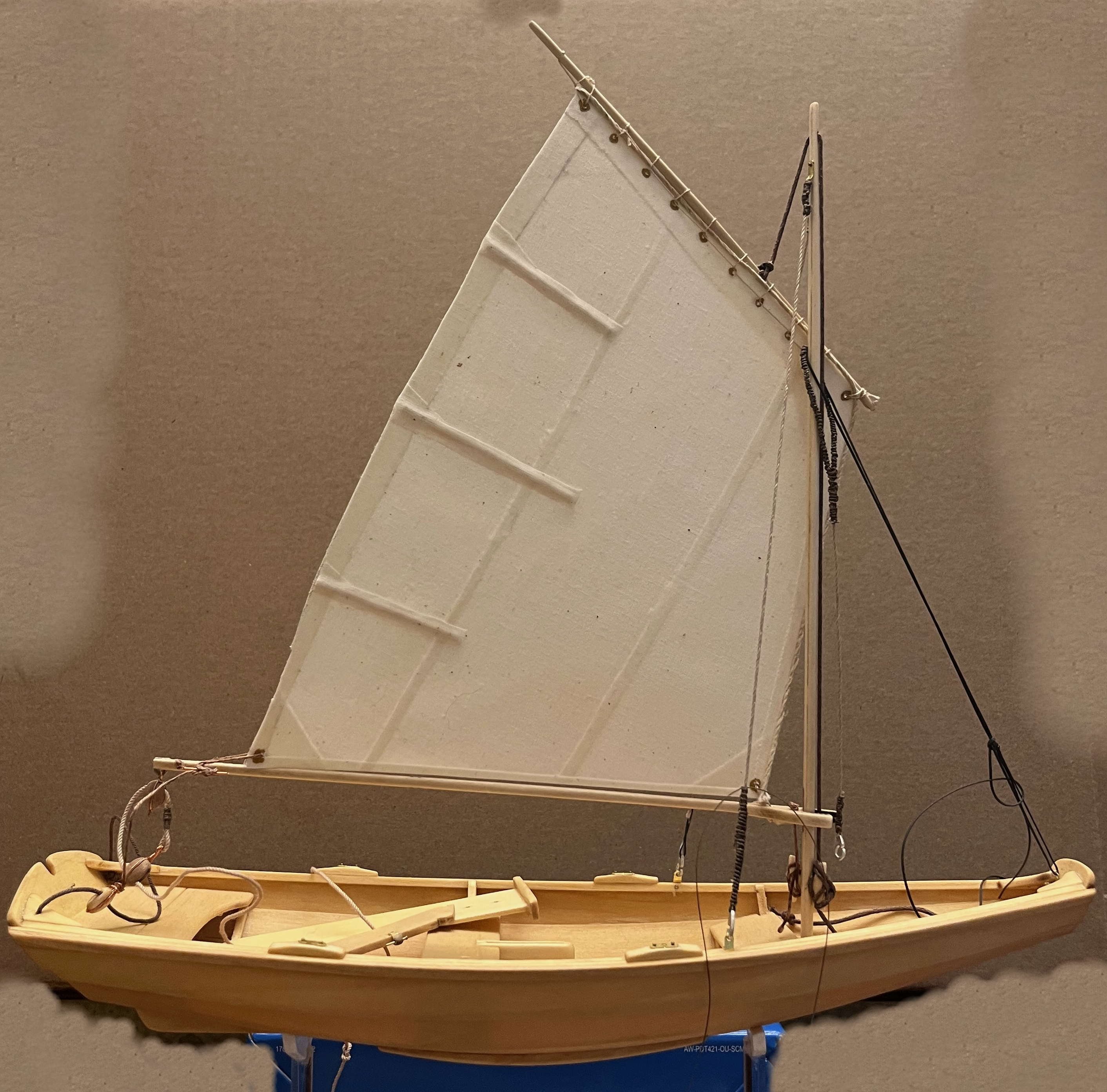
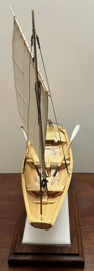
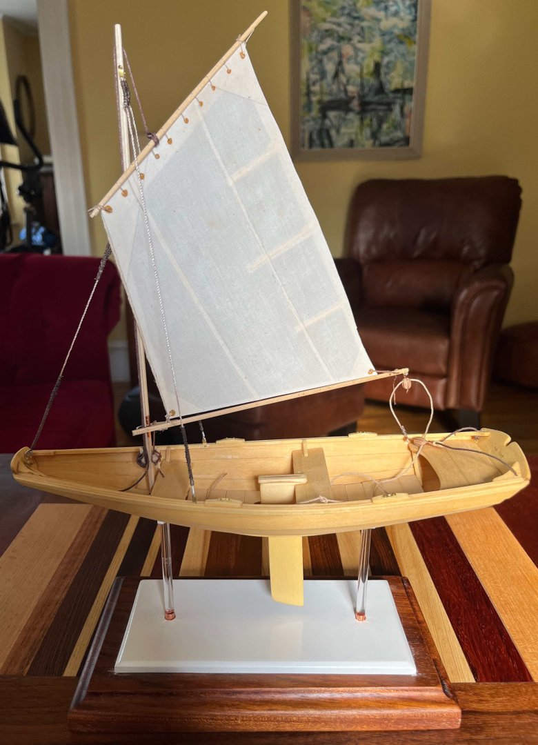
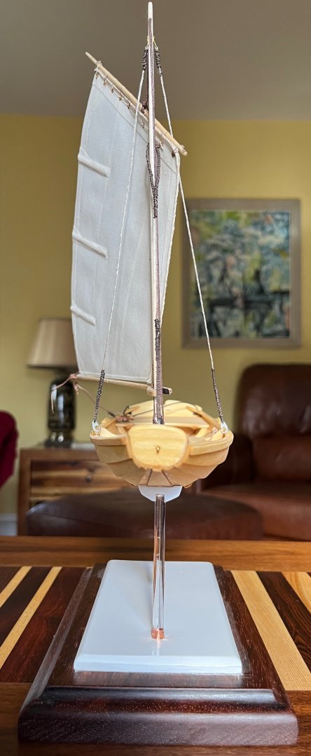
FINISHED Or that's what I'm declaring anyway: In truth, that mainsheet is refusing to lie quitly where it wa put, so it will likely need more attention with white glue: But I'm still calling the model "finished". This build log isn't quite done though. However, my final thoughts will have to wait for morning: The 7th game of the World Series is nearing its climax as I type! Trevor


- 167 replies
-
- 10
-

-

-
- Norwegian Sailing Pram
- Model Shipways
- (and 1 more)
-
Welcome aboard, Gus! Your expertise in full-size boats will be invaluable -- not only in your own model building but to the rest of us on MSW also. Hope to see your progress with the Whitehall soon. Trevor
-
Thank you, @king derelict. You are too kind!
- 167 replies
-
- 1
-
-
- Norwegian Sailing Pram
- Model Shipways
- (and 1 more)
-
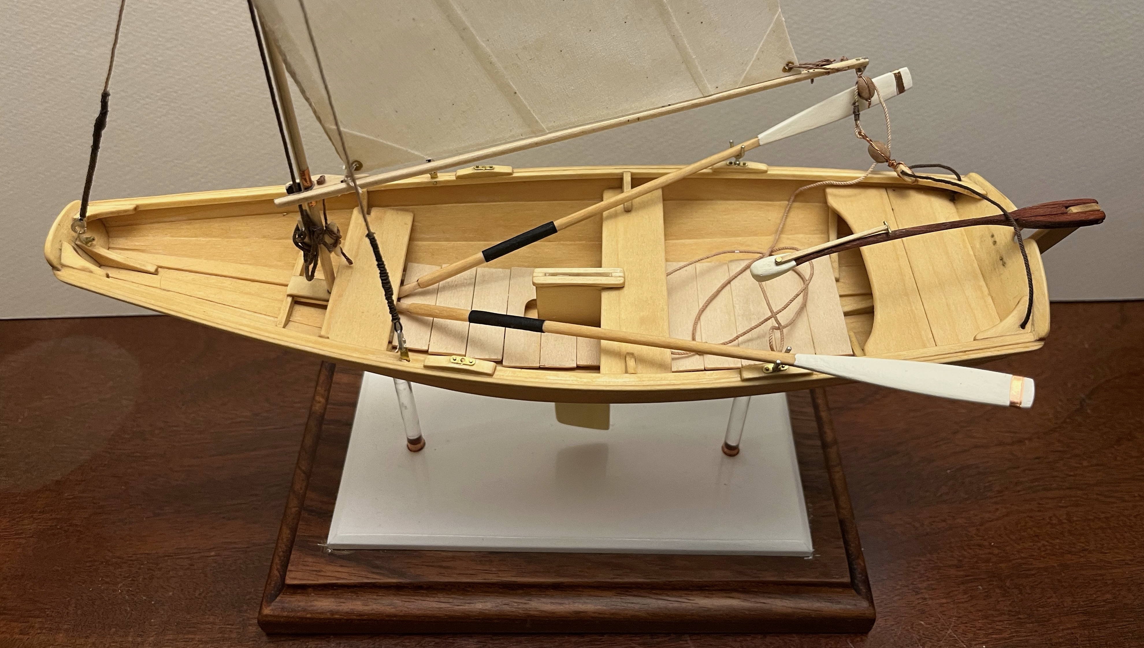
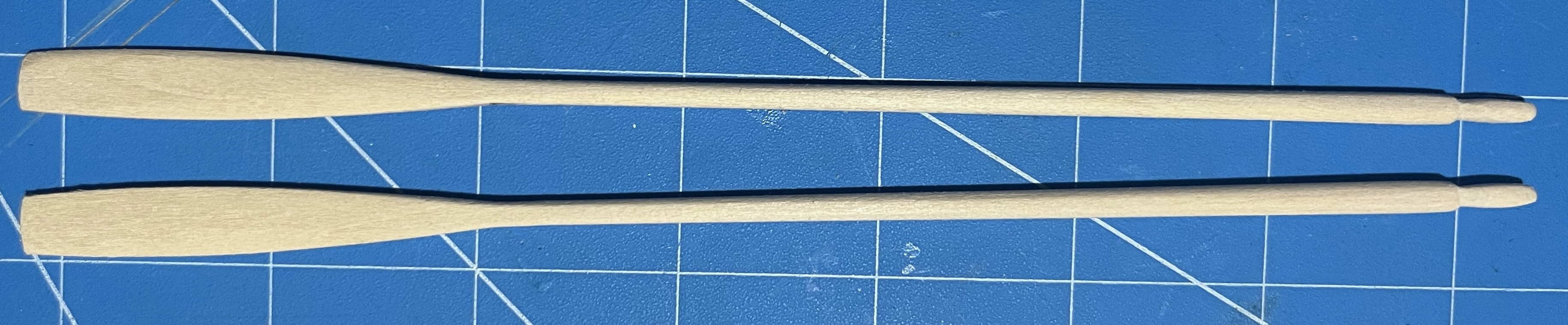
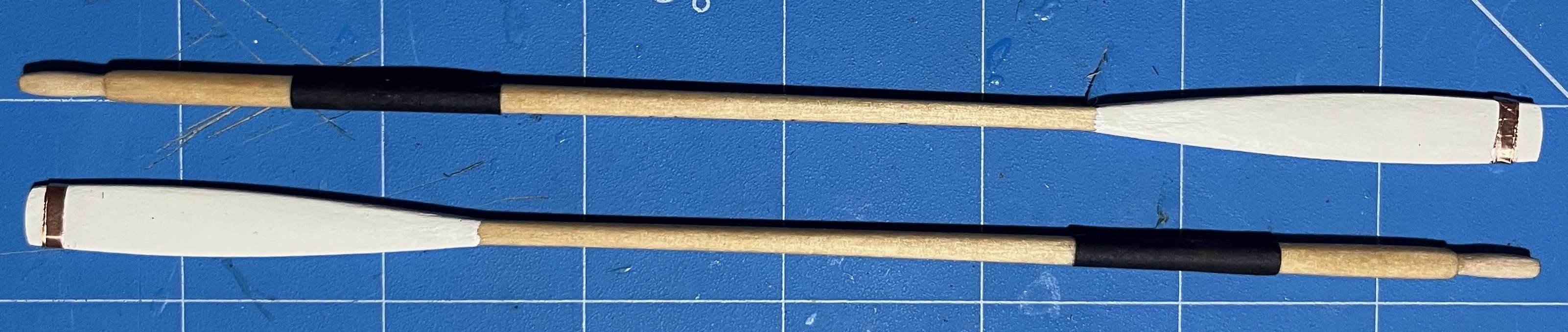
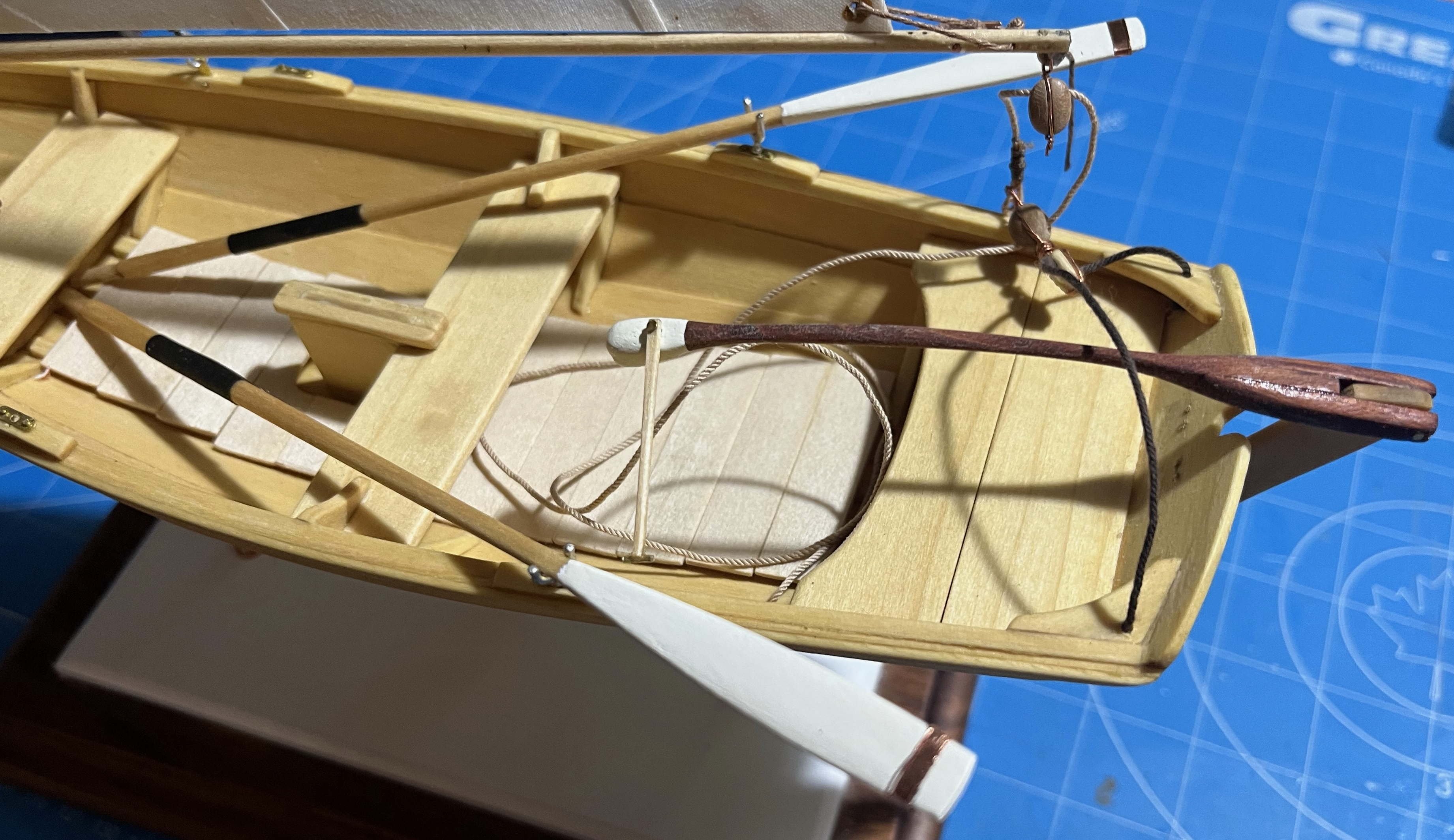
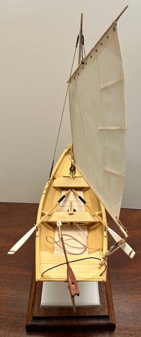
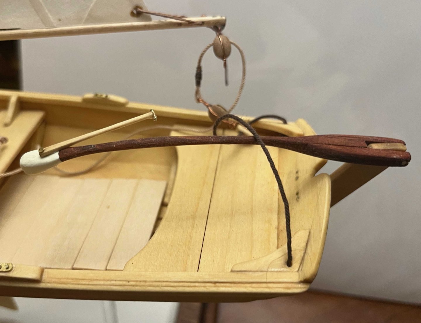
Oars and Rowing the Pram: The pram is designed with two rowing positions, one for each thwart, and (many steps ago) I added the four wood-and-brass fittings for holding the rowlocks. (The latter are technically "crutches" but nobody remembers that!) The kit comes with four rowlocks and laser-cut blanks for four very elegant oars. However, I very much doubt that the full-size boat could be rowed by two people. Certainly, once the mast is stepped, an oarsman on the forward thwart would forced to sit ramrod straight, pulling with arm muscles but unable to use the power of his/her back. That would quickly prove exhausting. Even with the mast left ashore, two adults would have trouble: The one on the forward thwart would be forever hitting the back of the other, when leaning forward to bring the oars towards the bow to begin the next stroke. Maybe two small teenagers could row together but I see the pram as a boat for one oarsman -- one usually sat on the midships thwart but with the forward position available when going for a quiet evening row with a significant other draped across the sternsheets. (Politically correct here: I make no assumptions about the genders of the two!) With the weight of the decorative individual far aft, the oarsman would have to move to the forward thwart to maintain fore-and-aft trim. So: Only one pair of oars aboard, usually used in the after rowing position (the one at the midships thwart). With that decided, preparing one pair of oars was straightforward and fully explained in the kit instructions, so no need for me to add much here. Mine turned out as: Oar handles are supposed to be left as bare wood. (The idea is that your hands blister less. Mine get torn up anyway, so I wear padded weightlifter's gloves when rowing any serious distance!) To simulate bare spruce, I used the ModelExpo clear finish, as with my pram's floorboards. The looms and shafts I did with tung oil, to simulate varnish -- as with the pram's hull. The blades I painted white, just for the visual effect on the finished model. The leathers were placed as per the instructions, without trouble. I used 1-inch strips of the paper that I had dyed with leather die for "leathering" the boom jaws. The instructions call for raised "buttons" at the handle ends of the leathers. I did not deign to have anything of the kind on mine: Buttons are needed by racing oarsman, who have to concentrate on speed and power, so cannot spare thought for finesse. Otherwise, they are only needed by rubes who haven't learnt to row. So not on my pram, thank you 😀 Oars used to come from the manufacturer with a copper strip nailed just above the tip of the blade, supposedly to halt any splits that may start there. The kit instructions call for painting the tips to simulate the metal. However, Shaw & Tenney of Orono (https://www.shawandtenney.com) have deeper and wider knowledge of traditional oars than anyone else I know of, and they discourage the reinforcement. Not unreasonably, they advise that the nails holding the metal strip create more trouble than the strip prevents. (Having used the same pair of their oars for 20 years with no splitting, I cannot disagree.) My inclination, therefore, was to leave the pram's oar blades white. But I couldn't resist the visual effect of genuine shiny copper. So I sliced some adhesive copper tape in half lengthwise and stuck that on. Call it artistic license! The remaining problem is what to do with the oars because, in truth, the kit ones are much too long for such a small boat. Even with the handles slightly crossed in front of the oarsman's chest, in the approved posture, so much of the oar would be outboard that the poor guy would wear himself out fighting the weight of the oar instead of working at pulling ahead. The trouble is even more acute with the sailing rig in use and the oars merely stowed (awaiting a need -- such as when the wind dies to a mirror calm and the sailor is called home for the family dinner). In fact, my choice for auxiliary power in such a boat would be a canoe paddle, rather than oars. Still, it would be a shame not to display the pram in all the glory the kit can provide. After some thought, I chose to show the one pair of oars in their rowlocks, with handles tucked under the mast thwart -- where they would be a nuisance while sailing but secure and ready to hand as the wind fails and the sail hangs like the flat board that the kits provides for. Rowlocks are glued in with CA, to avoid losing them, but the oars are loose. So, my version is: Now I just have to tidy up the running rigging. Trevor


- 167 replies
-
- 10
-
-
-
- Norwegian Sailing Pram
- Model Shipways
- (and 1 more)
-
Royal navy conversion of captured ships
Kenchington replied to Aldaris's topic in Nautical/Naval History
Short answer: It depends -- or I should say "depended". Depended on what was captured, how much damage had been done in the capturing, what need the captors had for the captured, what facilities were available for work on the vessel, how urgent the need to get her into service ... and probably a lot more besides. Given time and other resources, hulls could be strengthened, rigs converted to RN standards, guns replaced (along with all of the other armament gear to suit the new weapons) and more. Captured privateers might be converted into anti-privateering patrol vessels -- a different role requiring heavier armament, more stores etc., hence substantial conversion. Trevor -
Bower anchor project by Sizzolo
Kenchington replied to Sizzolo's topic in - Build logs for subjects built 1751 - 1800
Maybe not much too thick, as you are serving a cable to protect from chafe on the seabed, not serving standing rigging to keep the weather out and protect against chafe from the sails. Trevor -
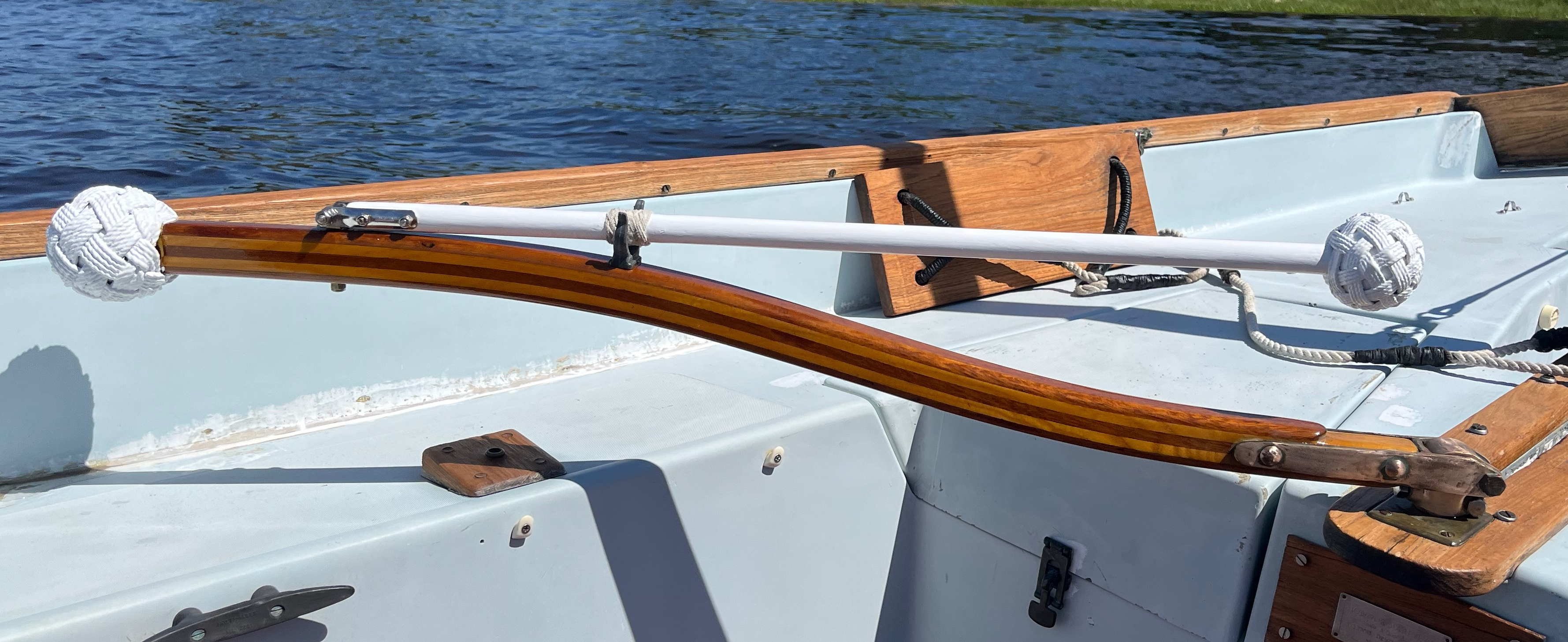
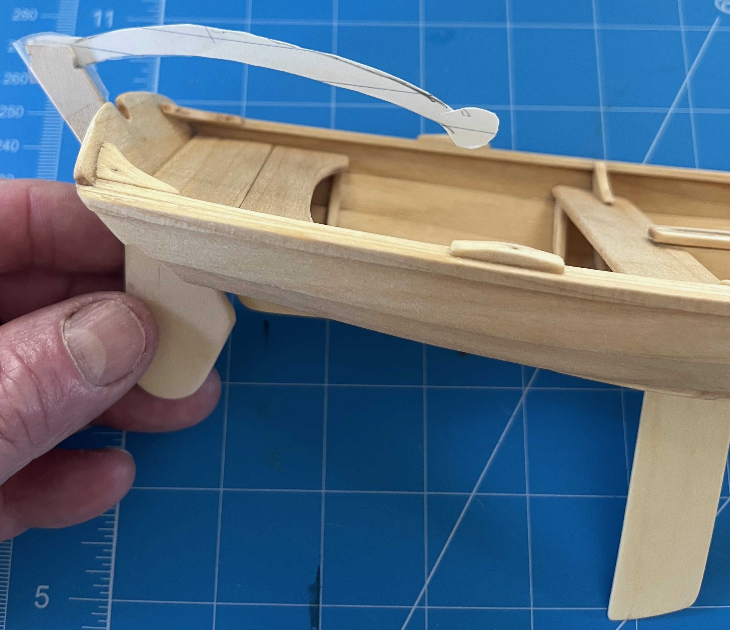
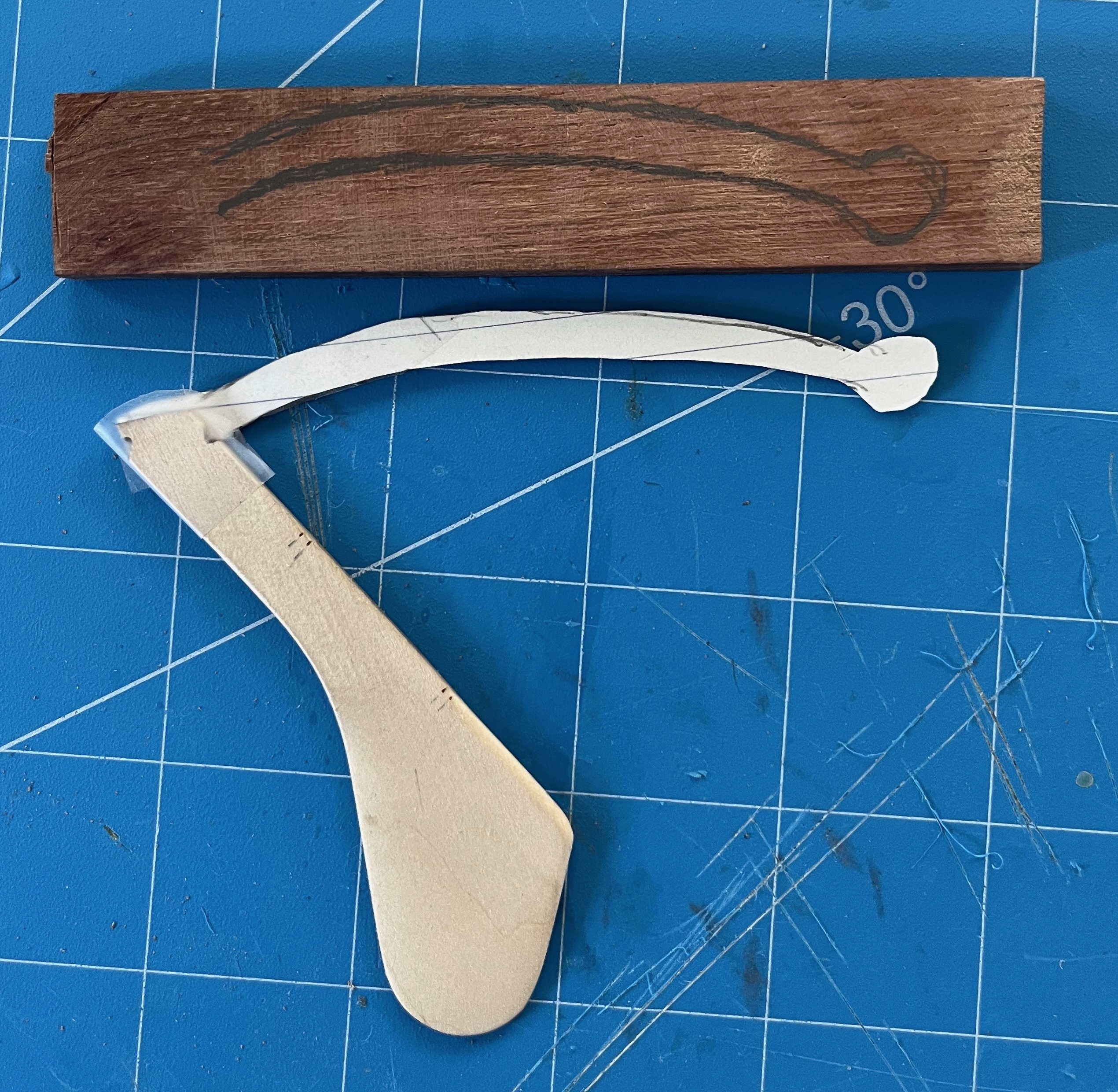
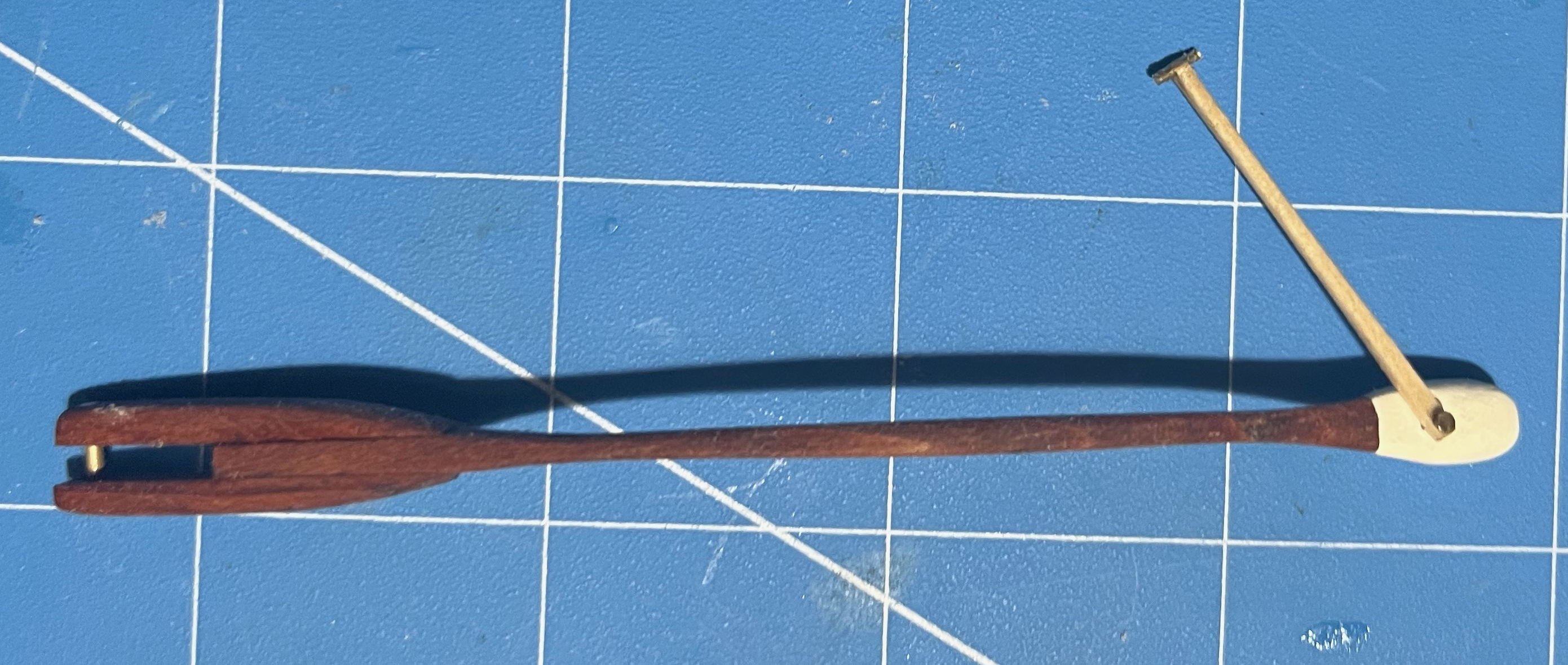
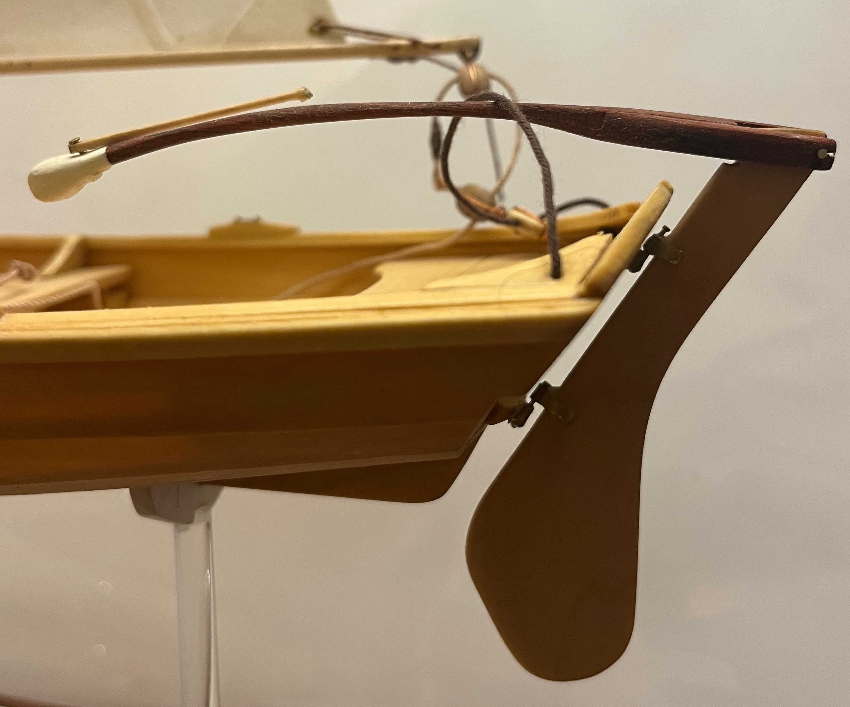
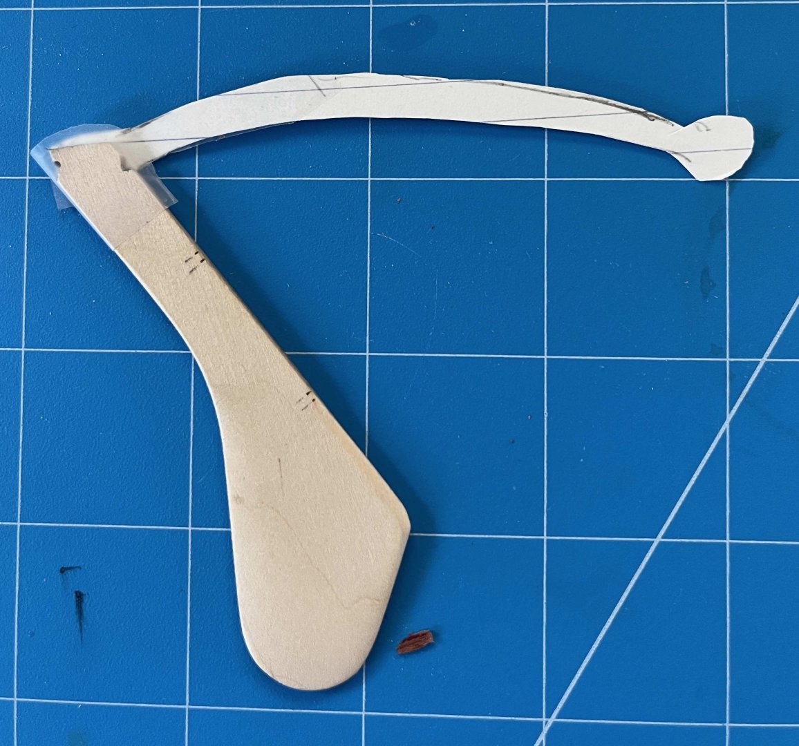
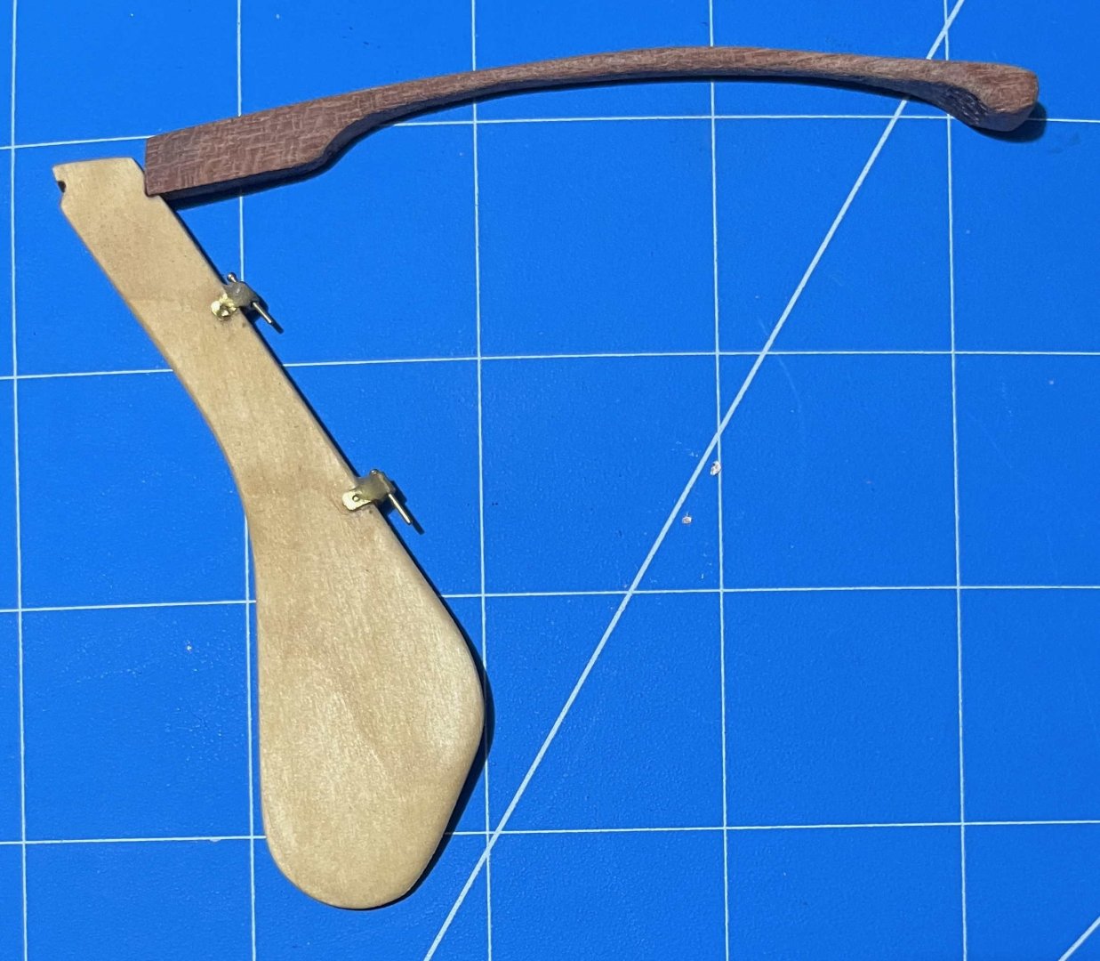
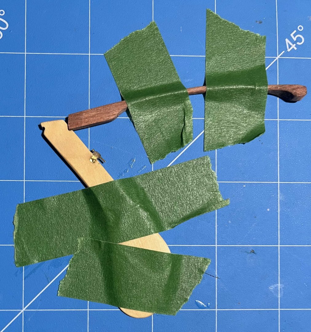
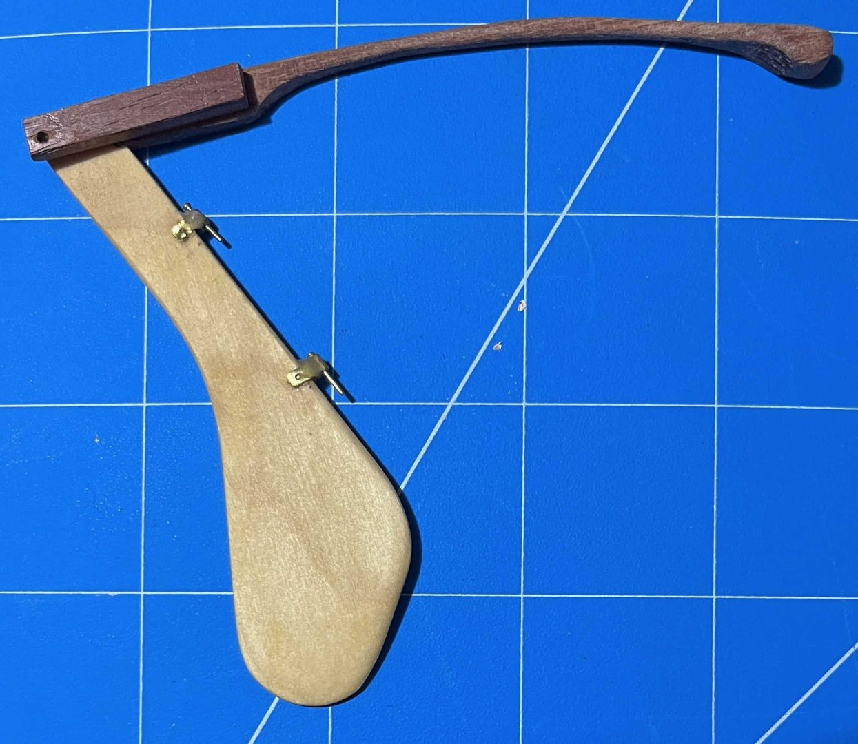
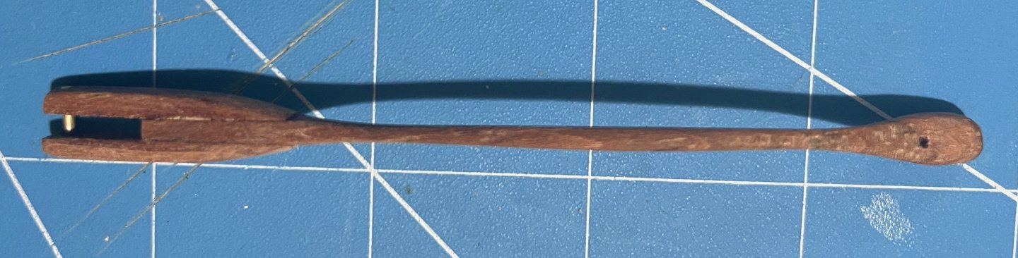
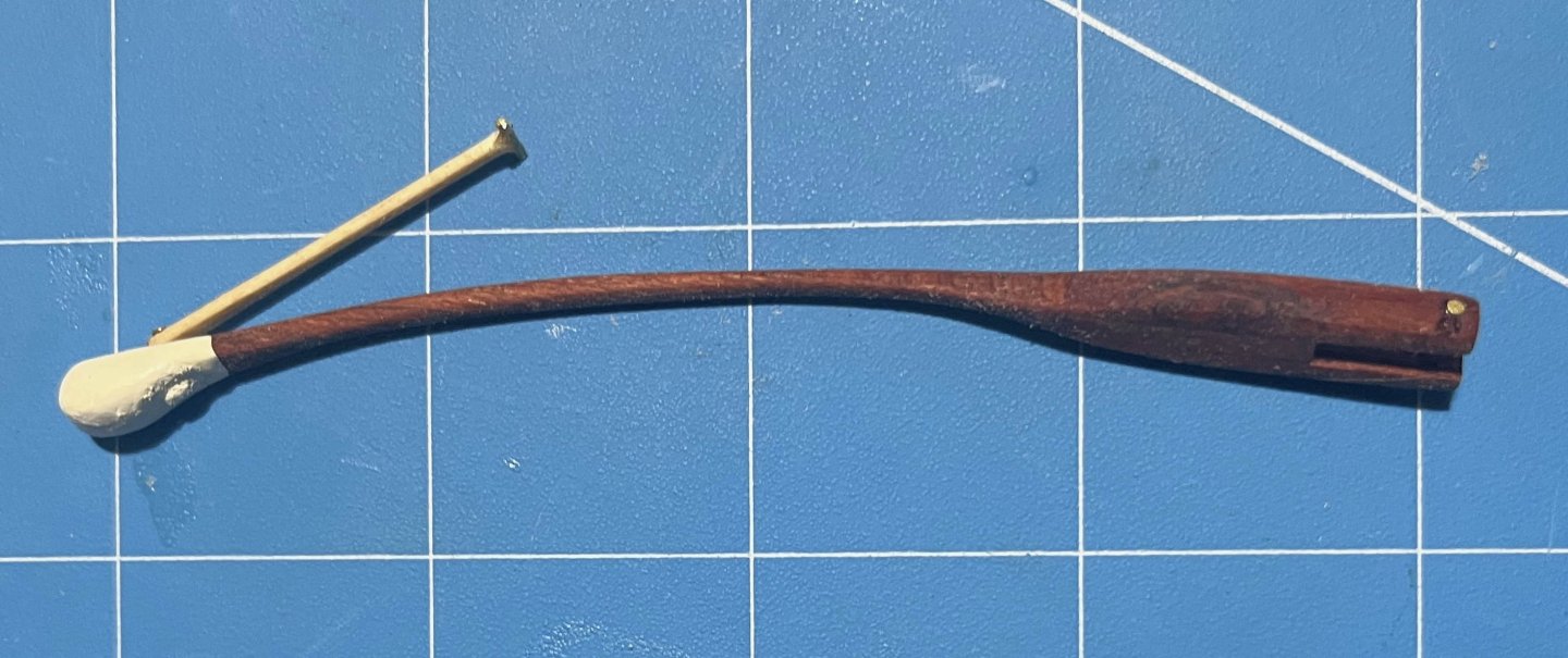
Tiller finally completed -- only seven months after I started on it! I explained the logic of my chosen solution back on post #89, so no reason to repeat any of that. However, discussion on another MSW thread through the summer got me thinking, so I will state one more point: When building a model of a specific vessel, Nelson's Victory for example, we should really strive to represent that one prototype as she was at some stage in her career. Heading off into fantasies of how she might have been, even though she wasn't, isn't what most of us are about. However, the pram isn't one boat but a design from which many full-size boats have been built. I am not trying to replicate any one of them specifically. Rather, I am aiming for a model of a boat as I would want her if I had one to the pram's design. I haven't tried personalizing the hull but I have modified the rigging, much as I would with a full-size boat. As it happens, my 22fter arrived with a short stick for a tiller, similar to the one in the pram kit. That had met the previous owner's needs but was dangerously inadequate when sailing in the sea breezes in my harbour. I added an extension right away and, as soon as I could, stepped up to the much-more-elegant tiller that the builder offered as an optional extra on new boats: The pram needs a different shape of tiller, to suit her different rudderhead and the angle of her rudder hangings, but I have gone for a similar concept. Since this was a substantial departure from the kit design, I needed to begin with a card template, to check the length and curvature needed, if the end result was to match the ergonomics of a solo pram sailor sitting astride the midships thwart: Then it was time to rough out a scrap of hardwood -- in my case a bit of jatoba, as I have oddments left over from a (full-size) boat project: Back in the spring, I got some way forward with shaping that but the Dremel cut too deeply at one point and I gave up for the summer. Maybe I should have started over but, in recent days, I decided to press on, even though the final tiller would end up thinner than I would have liked (about 1 inch diameter, if scaled up). After a whole lot of hand sanding, I ended up with a near-final shape, matched to the rudder, though with extra wood left at the rudder end as I could not be sure where the side pieces would lie: Also in the spring, I made two side pieces, following the kit's design but longer and in jatoba. I checked the alignment of rudder and tiller on the model (then checked again, and once again). Happy with that and to be sure that everything would line up, I taped the rudder and tiller down: then slipped a brass rod loosely into the hole in one side piece, placed that in the notch in the rudderhead and lined everything up. Oily tropical hardwoods can best be glued as though they were solid plastic -- meaning CA. A dollop of that on the tiller (avoiding the rudder) and the side piece was pressed into place. Once set, the whole thing could be flipped over, taped down again and the second side piece added in the same way. That gave me: Next was a whole lot more sanding, not least to make the top and bottom surfaces of the main tiller and its side pieces flush. Also to smooth the junction between those into a prettier curve. Then I tried putting annealed brass rod through the holes in the side pieces, following the kit instructions. Putting rod into holes was easy but when I tried to make heads out of the stumps of the rod, I just bent the metal and cracked the wood. So I fastened a short bit of rod into place with CA, filed down the metal and sanded the glue off the wood. With a whole lot more sanding, shaping and a hole drilled for the tiller-extension's pivot, I got to: That got its fancy end dipped in white paint and the rest wiped down with tung oil, bringing out the rich colour of the jatoba. Meanwhile,. I took the kit's tiller extension but did not even try inserting the brass crossbar as the instructions want it done. The diameter of the provided rod is very nearly as large as the thickness of the basswood extension, leaving no room for error and very little strength. If the pieces were double their thickness, I would have fitted a wooden crosspiece with a half-lap joint instead, but that was beyond me too. So I gouged a slight groove into the very end of the extension and glued a bit of brass rod there, using CA again. My attempt to form a head on the next piece of rod was as unsuccessful as the previous one had been, so I made the extension pivot from a brass nail, glued into its hole, cut, filed and painted over. That gave me a finished tiller unit that looks like: And in place on the model: Not as neat and nice as I had it in my mind's eye -- but very little turns out that well! Anyway, I'm happy with the final outcome, not least it's colour contrast with the rest of the pram. Now I have oars to finish, running rigging to tidy up and then I think the model will (finally!!!) be finished. Trevor


- 167 replies
-
- 8
-
-
- Norwegian Sailing Pram
- Model Shipways
- (and 1 more)
-
I'm with @catopower: Trailboards and the like were typically carved wood, with master carvers either part of a yard's workforce or else moving from yard to yard as each had a vessel nearing completion and ready for her fancy work. When in service, the carvings would typically be picked out in white, yellow, gold (paint) or even gold leaf for fancier vessels. (Gold leaf was still common for the lettering of names on yachts into the 1960s.) I'm not sure why they still show as pale in photos of derelicts. That might just be the angle of the light or could the carving be in a different kind of wood from the surface it was fastened to? Trevor
-
Bower anchor project by Sizzolo
Kenchington replied to Sizzolo's topic in - Build logs for subjects built 1751 - 1800
I don't think I could do as well at 1/1 scale! And I have tried: Not an anchor ring but one on a mooring buoy. Trevor -
Thank you or your support, gentlemen! After snatching some brief time to work on it, the standing rigging fix is now done: I will have to make changes to the mainsheet and its rope horse, but that will best wait until the tiller and rudder are done. The shorter, tighter horse might complicate repeated test placings of the rudder/tiller combination. I resumed work on the tiller last night, so progress picking up a bit. Trevor
- 167 replies
-
- 7
-
-
- Norwegian Sailing Pram
- Model Shipways
- (and 1 more)
-
Bower anchor project by Sizzolo
Kenchington replied to Sizzolo's topic in - Build logs for subjects built 1751 - 1800
Very probably. Steel might well have seen "rounding" as one version of "serving", yet still distinct from the form of serving used on the standing rigging. It would not have been only a change over time but also variations in usage at the same time. One might hope that technical nautical terminology would be clear and concise but it wasn't and isn't. Clarity of understanding depends on context and, even then, confusion can reign. I have long wondered but never gone in search of a definitive answer. My best guess is that most of the chafing gear ended where the cable met the anchor ring (which had the protection you are now adding). The best way to retrieve a lost anchor was to haul on its buoy line. My guess is that Steel meant that the part of the cable most likely to drag across the bottom should be of chain, with the hemp largely off-bottom -- that at a time when chain was becoming affordable but before people were willing to turn to all-chain cables. Trevor -
The only time I sailed in a ship with bowlines (the Rose, before she went off to play at being Surprise), we furled the sails with the bowlines attached to their leeches. Thus, coming at the question from the English side, I was surprised to discover, when reading Jean Boudriot's 74-Gun Ship, that French practice was to release the bowlines from the sails! That seems like a lot of unnecessary extra labour, when setting sail, though it doubtless had advantages. Trevor
-
Those who are not members of the Society for Nautical Research will probably not have heard but the SNR produces a podcast series -- a series which seems to be freely available, not restricted to members. The most recent contributions concern HMS Victory and may interest those building models of her. https://snr.org.uk/the-mariners-mirror-podcast/where-nelson-died/ should take you to an account of the death of Nelson and https://snr.org.uk/the-mariners-mirror-podcast/hms-victorys-conservation/ to one on the conservation of the ship. There are also videos on the SNR YouTube channel, again apparently open to all comers. For the one about Victory: Some entertainment value, if nothing more! Trevor
-
- 2
-
-
Anchor Knot
Kenchington replied to DennisL's topic in Discussion for a Ship's Deck Furniture, Guns, boats and other Fittings
For the heavy hemp cable of a naval brig of 1806, some form of anchor clinch would be used. I've seen various alternatives illustrated but you could use the one you show. I think that is the one that Steele illustrated (though I haven't checked). What you are calling an "anchor bend", I know as a "fishermen's bend" -- a more-secure alternative to a round-turn-and-two-half-hitches. That's great for fastening a light hawser to an anchor ring (and is widely used in modern small craft) but not much of an option with a warship's cable. Trevor -
Bower anchor project by Sizzolo
Kenchington replied to Sizzolo's topic in - Build logs for subjects built 1751 - 1800
I have the 1999 Dover facsimile edition and that text in the last full paragraph on a page headed "67" then "Anchors etc." Trevor -
Bower anchor project by Sizzolo
Kenchington replied to Sizzolo's topic in - Build logs for subjects built 1751 - 1800
You may finish with the most authentic model of a hemp anchor cable ever! One final thought before I bow out and leave you to it: Lever wrote about contemporary (to him) seamanship for aspiring would-be sea officers. I think we can trust him to have known what he was writing about and to have attempted to communicate it accurately, though his presentation falls short of expectations for modern technical manuals. Ashley was writing about knots, as an enthusiast and for other enthusiasts of arcane ropework. Where he stepped away from the details of twisted cordage and described the practices of former times, I think we should be a bit cautious in accepting what he set down at face value. His claim that his #3351, the form of worming that he terms "keckling", was used at the anchor ring and the hawse strikes me as unlikely. At the anchor ring and along as much of the cable as might drag on the seabed, as Lever hinted, seems altogether more probable. Nautical terminology has not been as stable and standardized as we might wish, while the meanings of words in New England (e.g. Ashley) and (Old) England (e.g. Lever) could differ. So I'll not say that Ashley was wrong to call his #3351 "keckling" but neither would I be too sure that it was what Lever meant when he used the same term. As to later authors: John Harland's and Jean Boudriot's books are superb -- something I would not say of the output of many of their (and our) contemporaries. However, they necessarily drew on much the same original material that we now have access to. While I deeply respect their competence at interpreting that evidence, and must not be ignored, we should still make our own examination of the contemporary sources, where possible. Trevor -
Bower anchor project by Sizzolo
Kenchington replied to Sizzolo's topic in - Build logs for subjects built 1751 - 1800
Served in way of the hawse holes, to prevent local wear there. In deep-sea ships, anchoring rarely and then in varied water depths, the service would be applied where and when required, then stripped off. By Lever's account, coasting vessels had three pre-set lengths of cable to veer, with a permanent service at each length. (Not that they couldn't apply a temporary one when some other length of cable was essential.) I think (though his words are open to interpretation) what he meant of the length of cable nearest the anchor was wormed (all the way to the first service in coasters, with the worming projecting to take the wear on the seabed), with keckling over that, "rounding" on top and "plait" on top again -- warships only having the first four fathoms from the anchor covered in rounding and plait, with those and the next three covered with keckling. Ashley illustrates three forms of "keckling". His #3605 is a type of ringbolt hitching and his #3117 is similar but used to hold two ropes together, while his #3351 is worming much as we are discussing, with a single length of 3-inch rope in one of the contlines of the cable "to protect it at the anchor ring and at the hawse pipe". Quite what Lever meant by the term is beyond me, unless he intended something like serving but applied with hitches, like Ashley's #3117 and #3605, hence less likely to fall away when one turn around the cable gets worn through. Maybe it was easier to apply tightly, with the hitches, when the cable was too big and awkward for a serving mallet to be used. (That's just my speculation.) Ashley has "rounding" as his #3350 : a "service of old rope" formerly used on cables at the hawse hole. "Plait" presumably meant some sort of sennit or turkshead. At first, I thought Lever meant lengths of sennit wrapped around the cable but I rather suspect that the plait was worked directly on the cable, forming a tight, tubular net over the whole mass of chafing gear. It all amounted to far more untidy complexity than I have ever seen in a model. And far more work for the crew. But if we'd ever hung onto an anchor, with the seas breaking on a lee shore close under the stern, while fretting over what might be happening to the cable where it was being dragged across a rocky bottom, maybe we would not mind the extra labour! Trevor -
Y.T. proved the point while I was typing!
-
Good question! Treenails were/are sometimes but not always the same wood type as the pieces being fastened. However, their heads show the end grain and hence contrast with the material around, so they don't exactly disappear. Run your hands over a treenail-fastened hull and, unless there is a thick coat of paint, you'll have no trouble at all seeing them. But take a look at photos of the decks of museum ships and you will often have to peer closely to see any fastenings at all. They don't form a noticeable aspect of the overall impression. (Granted, many surviving ships have deck planking bolted to steel, with wooden plugs over the bolt heads, but the end effect isn't so different from a treenail.) That's just an effect of a more-distant viewpoint. At typical model scales, it would likely be more realistic to display smooth planking, without visible fastenings. But all ship models are stylized and if someone likes a visible treenail pattern, that's just a personal preference. Trevor
-
Bower anchor project by Sizzolo
Kenchington replied to Sizzolo's topic in - Build logs for subjects built 1751 - 1800
Very wise of you! I was working more from logic and the purpose of worming the cable -- which is no substitute for contemporary evidence. However, a search of my shelves led to one entry in Darcy Lever's "Sheet Anchor" (p. 67 and referring initially to practices in coasting vessels, which needed to anchor frequently, of course): "The working Cable has always the Services kept on, of which there are three, viz. the short or windward Service at about forty-five Fathoms [...] From the anchor to the short Service, the Cable is wormed with twice-laid Stuff, sufficiently large to project above it, which is a great Preservative against its being damaged by foul Ground. It is then keckled, and rounded with Plait. [...] Men of War and East Indiamen have about seven Fathoms of Keckling, four of Rounding, and four of Plait." I haven't checked secondary sources, though I expect Boudriot, Lavery and others have given their interpretations of warship practices. Trevor -
Bower anchor project by Sizzolo
Kenchington replied to Sizzolo's topic in - Build logs for subjects built 1751 - 1800
Might want to go a bit larger than that image shows. The idea when worming shrouds (before parcelling and serving) was to get a smoother surface, so a ruler placed along the wormed rope ought to touch both the worming and the strands. Worming a cable was a bit different. I think the idea was that the worming should take the abrasion on the seabed, leaving the cable itself less damaged. If so, that imaginary ruler should touch the worming but not the hawser-laid parts that make up the cable-lay. Then again, the length of cable nearest the anchor could have extra chaffing gear applied (though that is rarely, if ever, shown in models). The image does give a lovely example of the way the anchor ring was prepared! Trevor -
Bower anchor project by Sizzolo
Kenchington replied to Sizzolo's topic in - Build logs for subjects built 1751 - 1800
But only a little -
"LOA" should mean the overall length of the hull, so excluding all spars. Unfortunately, the term gets misused (perhaps most often by the museum-ship community) as what has alternately come to be called the "sparred length", hence including the bowsprit (and jibboom, if one is carried -- which is not the case with Bluenose) plus the overhang beyond the stern of any boom (main boom for Bluenose, mizzen boom for a three-master, spanker boom for a square-rigger). I don't think there is any way to be sure which meaning someone else intended without knowing the actual length of the hull of the vessel concerned. For Bluenose LOA, properly so called, was (and for Bluenose II is) 143 ft. Bowsprit and overhang of main boom would be additional to that. Trevor
-
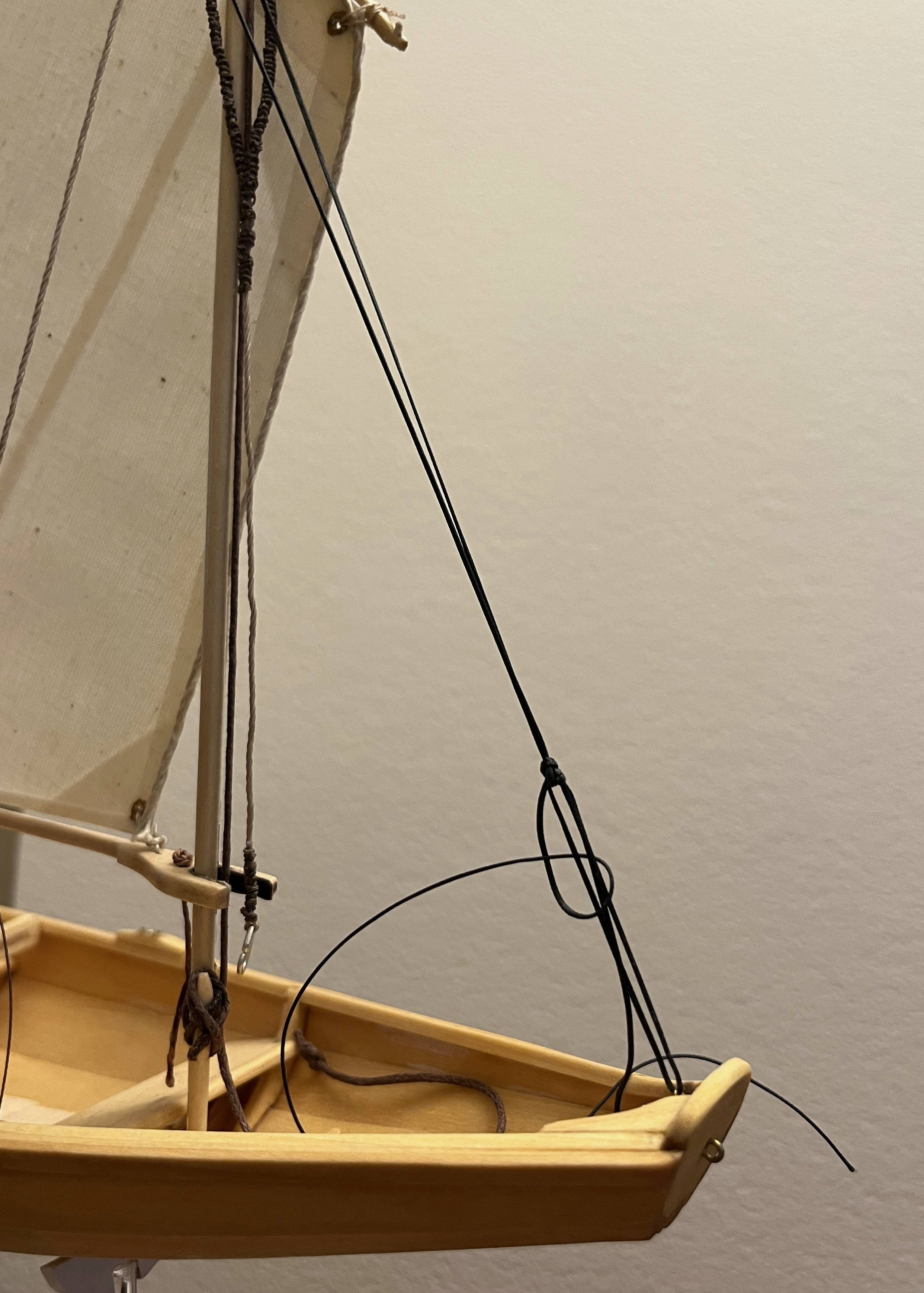
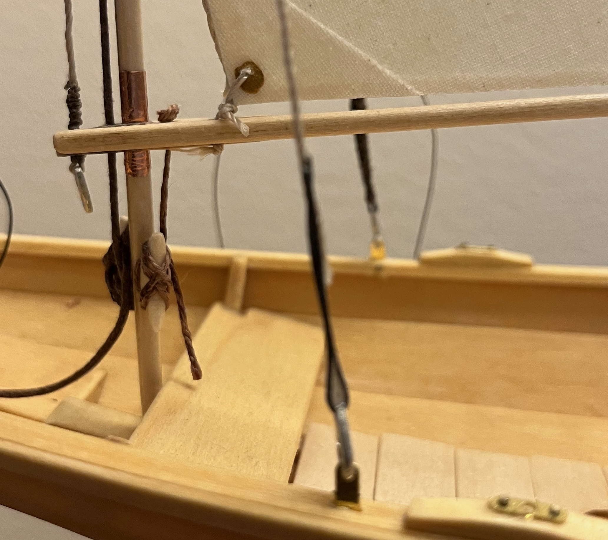
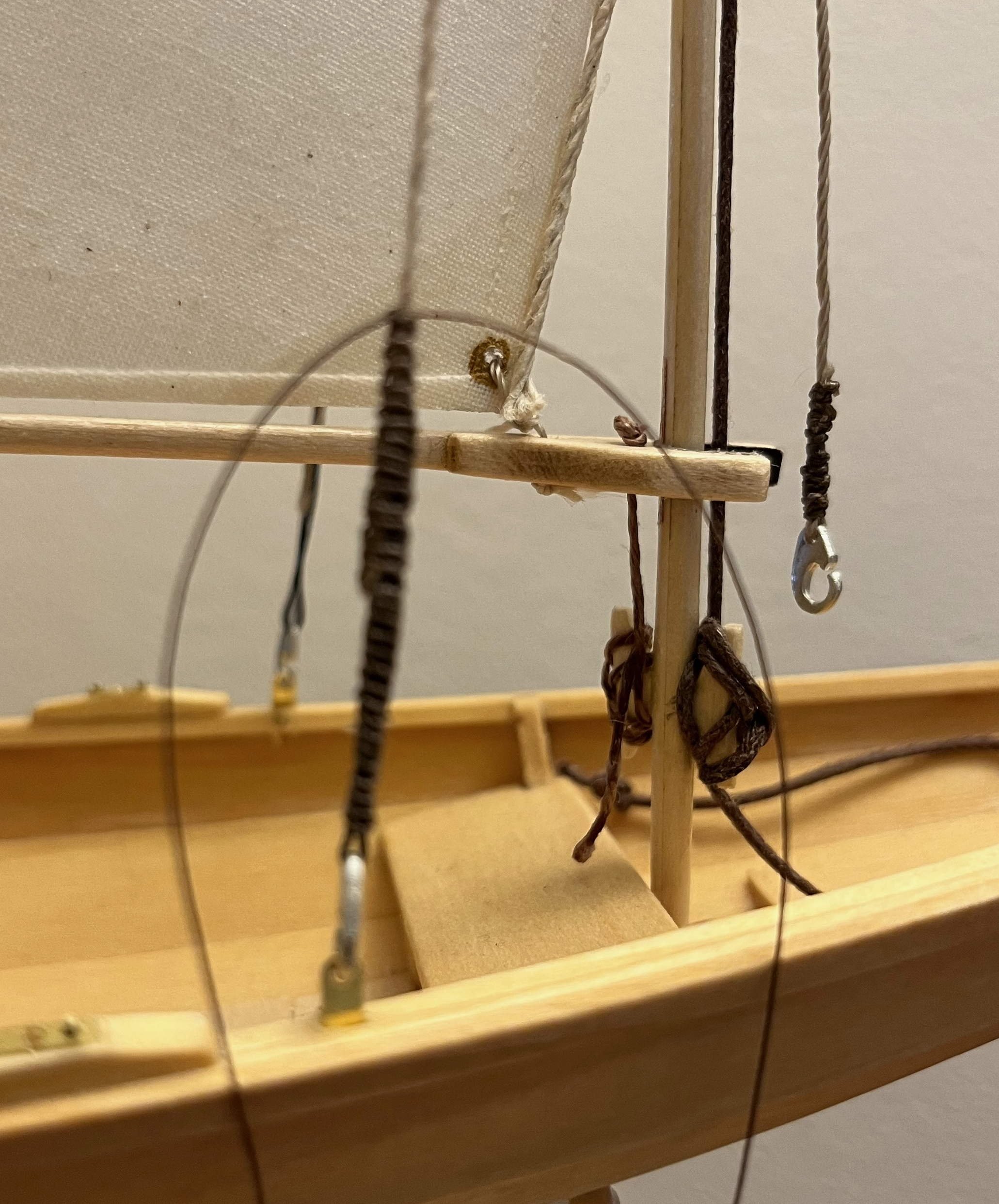
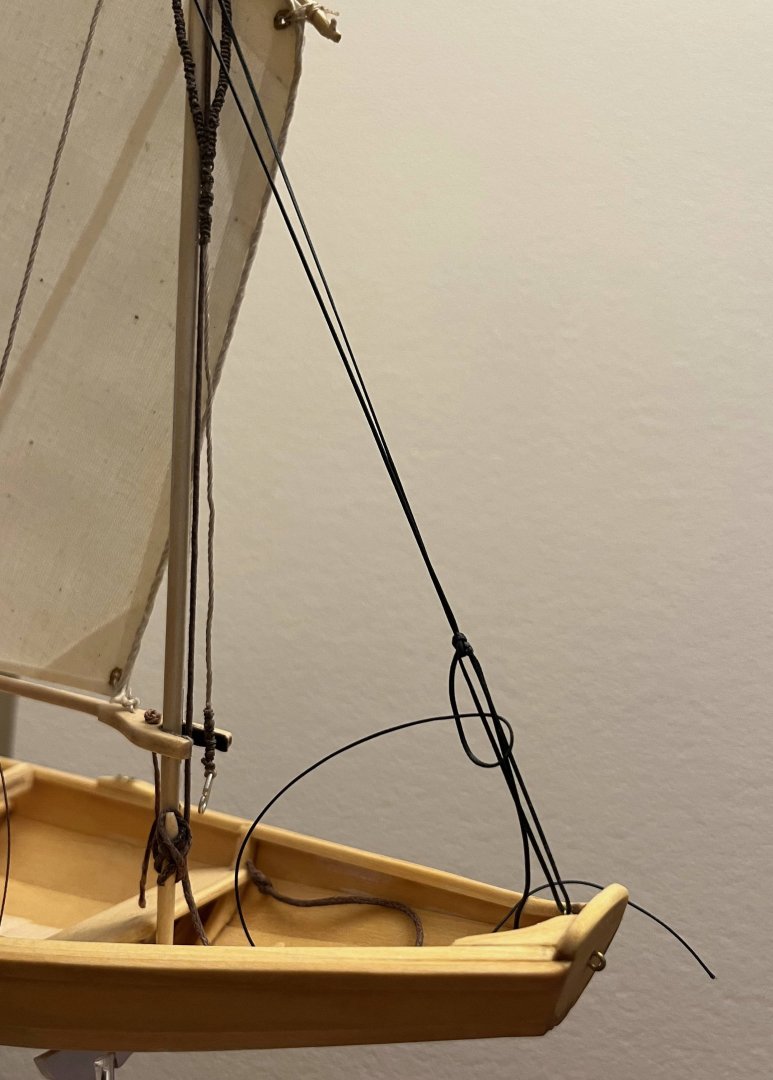
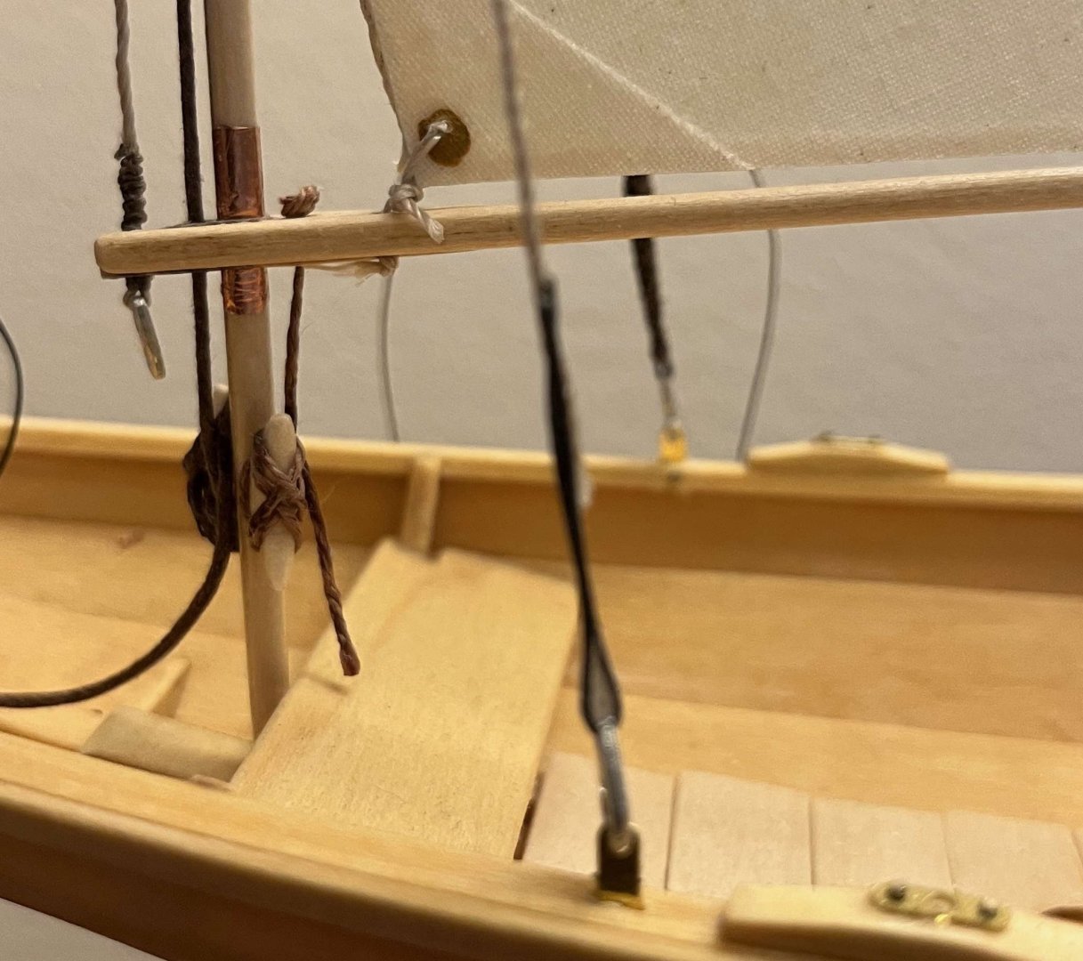
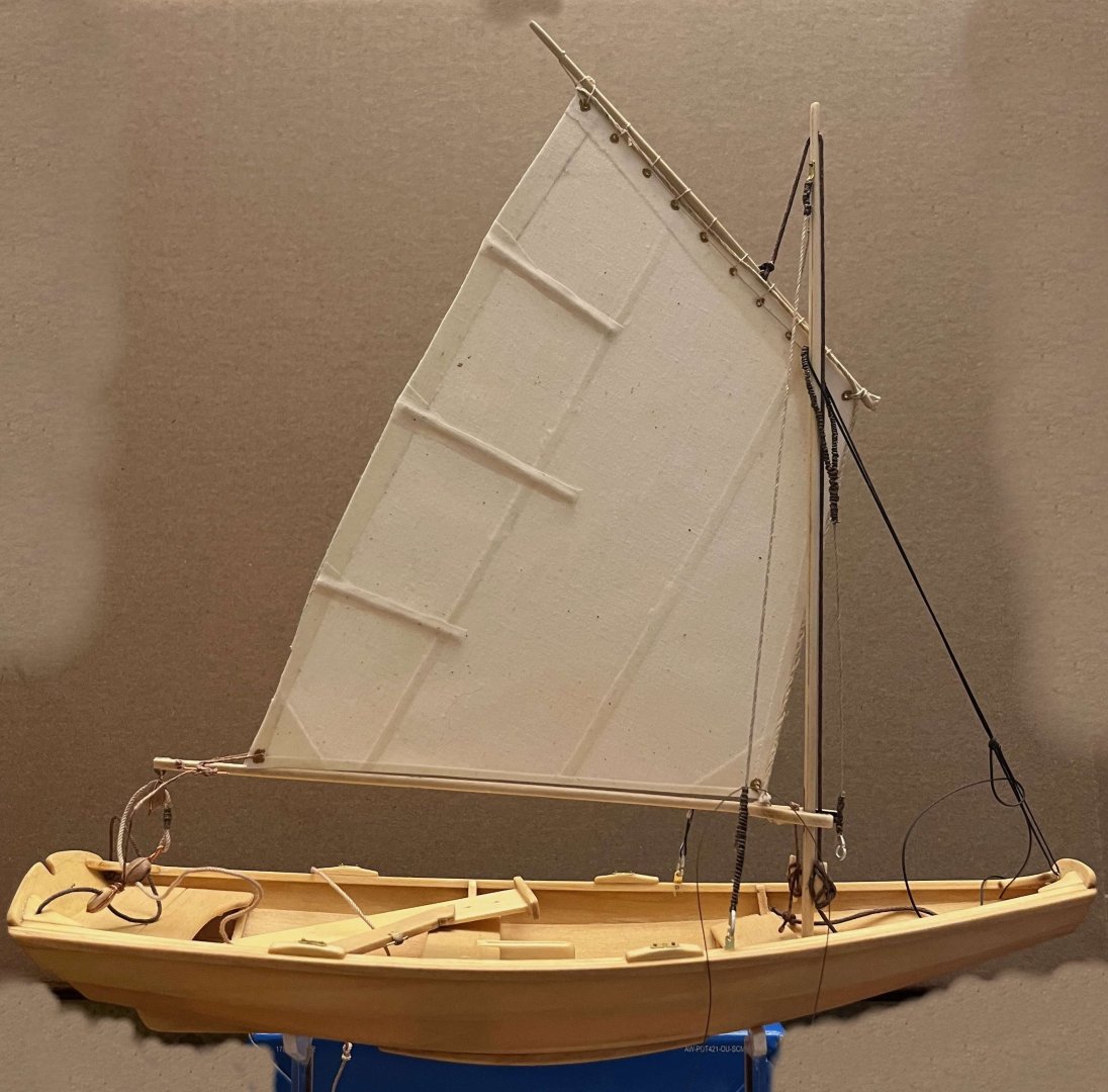
Six months gone since I last made any progress on my pram. Like others, I have been caught up in a whole mess of tasks (some rewarding, others less so) that have drawn me away from ship models -- from model building, though they have not stopped me being an annoying know-it-all on MSW! Back in April, I had come to accept the forward rake of my pram's mast and finally stuck when my attempts to produce the sort of tiller that I think the boat deserves proved more demanding than I had expected. However, staring at the model all through the summer, I decided that the rake had to be adjusted and that that would be an easier route back to re-starting work on the pram. So ... I still think it is best to get both shrouds the same length, hence the mast upright when seen from ahead or astern, then worry over tension in the rigging while finalizing the forestay. But it is clear that the rake has to be set approximately before starting on the shrouds. So I began by unhooking the existing forestay and rigged a length of thread in its place, adjusting that until I got the rake I wanted: Next, I cut away one shroud where it passed around its hook, at the chainplate in the rail. I cut away the "serving" (which I had faked with a length of Westcountry whipping) and "spliced" on a length of thread by gluing it to the cut end of the shroud with CA. Passed the thread through the eye in the hook, pulled until the mast was upright (port to starboard) and glued the other end of the thread back to the shroud: (Phone camera decided to focus that one on the mast, not the nearer shroud, but you can see the repair.) Next up, repeated that with the second shroud -- judging the mast upright by eye, though it proved to be as close as made no difference when I later checked with a small square laid across the rails. I have hidden the mess of glued ("spliced") ends with a lengthened "serving", though that's awaiting a touch of CA before I clip the ends of the serving thread: Again, the focus is off and the "serving" is lumpy where it passes over cut ends. Still, I now have the mast in a far preferable position: Still have to "serve" the port shroud, then make a similar adjustment to the length of the forestay. The mainsheet and the rope sheet horse will need adjustment ti suit the lower position of the boom end, but that shouldn't pose problems. Then it will be back to making an acceptable tiller, followed by onward progress to model completion! Trevor

- 167 replies
-
- 7
-
-
- Norwegian Sailing Pram
- Model Shipways
- (and 1 more)