georgeband
-
Posts
289 -
Joined
-
Last visited
Recent Profile Visitors
2,142 profile views


-
 Chris, Thank you for a most useful and informative article about copying pictures from the web. Could I ask you to venture into an adjoining minefield, one where the original source document is on paper? We all have our favourite reference books and some of these are long out of print. Two examples that I can point to are Modelling the brig Irene by Petrejus (1970), and Young Sea Officer's Sheet Anchor by Darcy Lever (1819 for original 2nd edition, and also 20th century reprints). There are lots of others which generally fall into these two categories: relatively modern but out of print, or antique but available as facsimile copies. I can scan pictures from books that I have, or find them already scanned on the internet. I believe that copies of pictures for personal use are legal and allowed but I do not know the position for wider distribution such as posting on MSW. Can you advise please? George
 -
I have had a look through Petrejus Irene to see what he says about Dutch build practices. Petrejus quotes several references but they are from around 1820 to 1840 so might not be correct for earlier practice. JC Rijk, Sheepsbouw, 1822. pp 132-134 HA van der Speck Obreen, 1843 JC Pilaar, Handleiding tot de kennis van het schip en deszelfs tuig, Delft, 1826 W van Houten, De Scheepvaart, Breda, 1833 I have had a quick look on Google but my knowledge of Dutch is minimal and I did not find any nice pictures... Perhaps someone else will fall down this rabbit hole of research. The information and its interpretation by Petrejus is centred on its relevance to Irene which was captured in 1811 and refitted. It might be relevant for De Braak. Overlap of plates on hull There is general agreement that the Dutch overlapped the plates on the hull in a conventional way. The trailing edge of one plate went over the leading edges of the plate astern. The upper edge of a plate overlaps the lower edge of the plates above it. Plates were fitted from the stern forwards and from the keel upwards. Overlap of plates on keel Petrejus has nothing specific about the order of plating the keel but he does write '32 ounce sheathing was used for the bows and for the parts between wind and water, 28 ounce sheathing for the rest of the bottom and 18 ounce for the lower side of the main keel, between it and the false keel'. Nail pattern on plates Petrejus shows a picture of a plate with nails in a square pattern (from van der Speck, 1843) but there are 5 rows and 14 columns for these nails. The square pattern could have been in use for a long time or it might be a more recent development. The proportions of the plate in Petrejus' picture are quite different from the standard RN plates. Could a copper smith simply use the pattern that someone else had shown him and there was no regulation about how to space the nails? How was the keel plated? My guess about this is that plates were laid lengthwise on the bottom of the keel, a single plate wide with the edges folded up over the sides by an inch or two unless the keel was wider in which case two plates would run in parallel. The photos placed above show copper coming from the keel-false keel join and extending enough up the side of the keel to give a tight row of nails. This row could be hammered in place after cut-down plates had been fitted to the sides of the keel. The plates on the side would have their top edge trimmed and bent to go over the lowest hull plates and were hammered down after the first hull plates were fitted. This sequence ties in with the bottom-to-top rule and the rule about lower plates overlapping upper plates. I have not tried to fit in the staples to this sequence and might return to it later if I feel brave. George
-
 paul ron reacted to a post in a topic:
HMS De Braak copper plates on salvaged wreck
paul ron reacted to a post in a topic:
HMS De Braak copper plates on salvaged wreck
-
 CiscoH reacted to a post in a topic:
HMS De Braak copper plates on salvaged wreck
CiscoH reacted to a post in a topic:
HMS De Braak copper plates on salvaged wreck
-
tlevine reacted to a post in a topic:
HMS De Braak copper plates on salvaged wreck
-
druxey reacted to a post in a topic:
HMS De Braak copper plates on salvaged wreck
-
ccoyle reacted to a post in a topic:
HMS De Braak copper plates on salvaged wreck
-
Chapman reacted to a post in a topic:
HMS De Braak copper plates on salvaged wreck
-
Knocklouder reacted to a post in a topic:
HMS De Braak copper plates on salvaged wreck
-
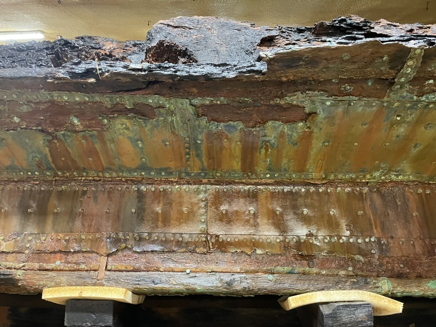
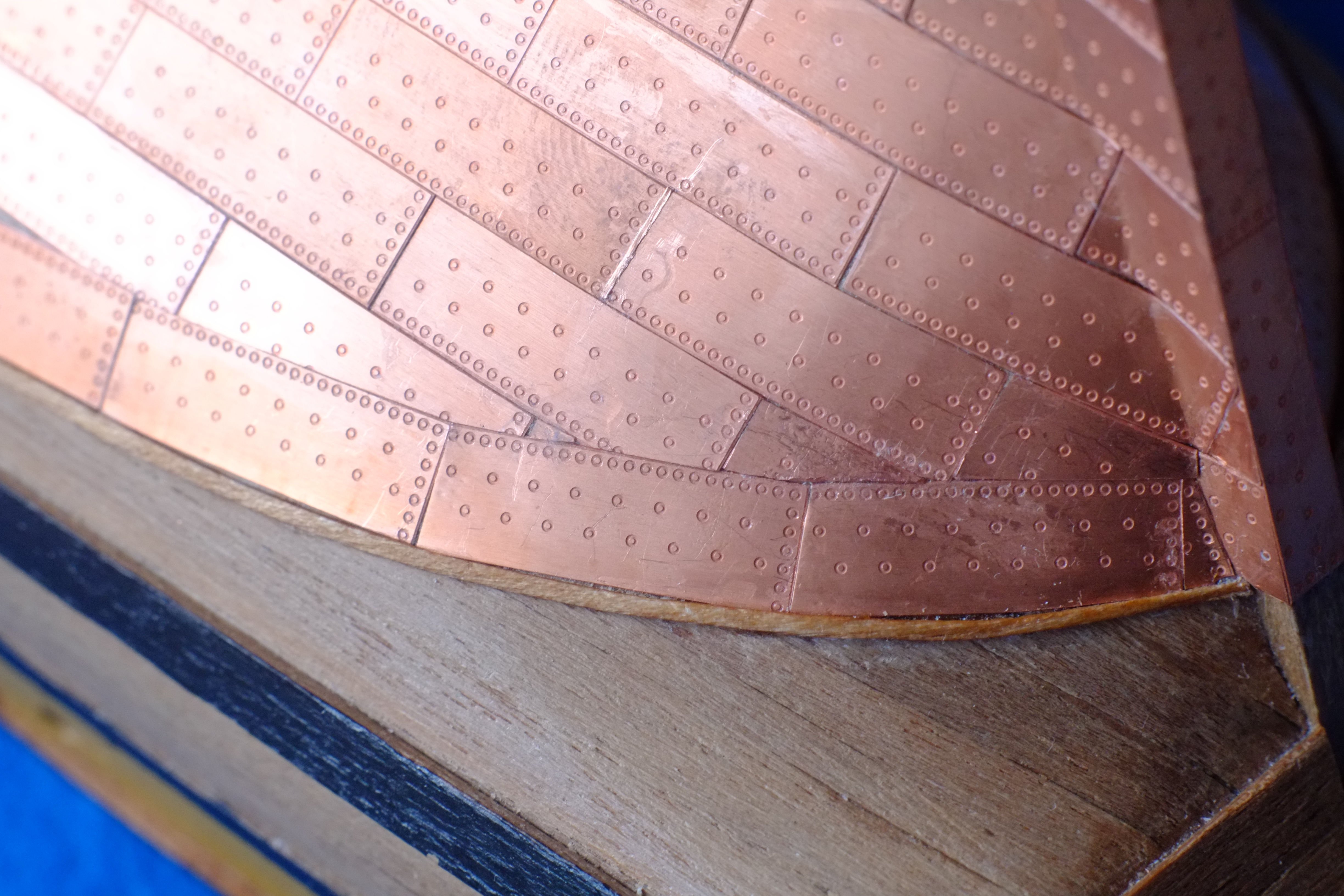
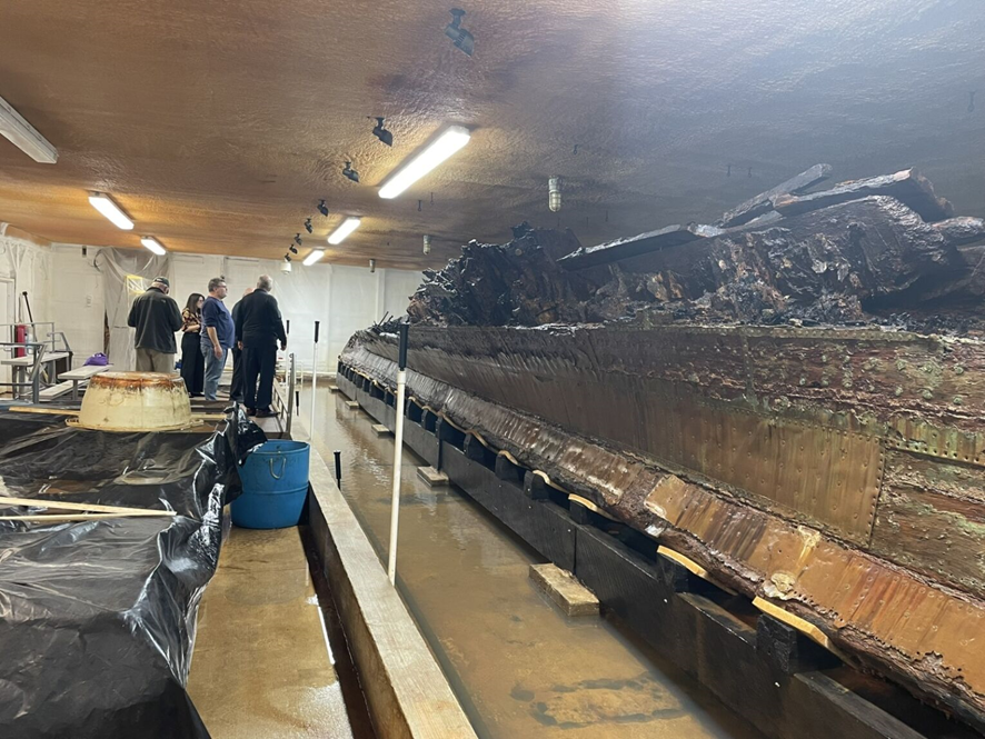
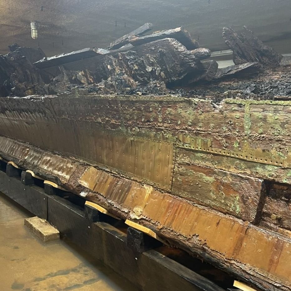
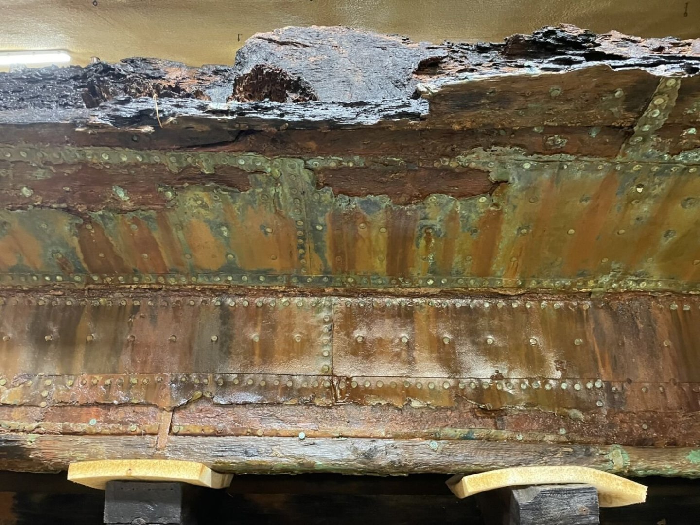
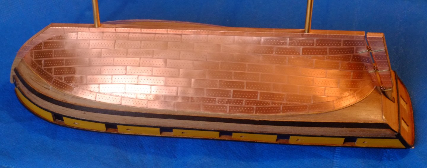
HMS De Braak (or just HMS Braak) was originally built as a cutter in 1781 for the Dutch navy. She was captured in 1795, modified into a brig and taken into the Royal Navy. Her career was short and in 1798 she capsized and sank in Delaware Bay. Recent salvage work has raised a large part of the hull which is now the subject of preservation work. Much of the coppering is intact and is a true contemporary record, not a recent replating such as on USS Constitution or HMS Victory. In my opinion it is most likely to have been applied during her refit in 1795-1797 though there is a possibility that it was applied by the Dutch. Can anyone shed light on this? Pete Stark in the 1805 Club sent me a collection of his photos of De Braak and I have attached some below. Thank you Pete for letting me share them. I recommend that you take a look at the club https://www.1805club.org/ which will be sponsoring the restoration of the ship's bell. 1. A wide view of the raised hull. It looks to me like the keel is near the bottom and the curved planking for the hull is above it. The vertical joins between the plates show that the plate to the left overlaps the plate to the right which indicates that the fore end is to the left and we can see the port side of the hull. 2. The plate at the centre of the next photo reveals the nail pattern. The top edge of this plate has closely spaced nails and it overlaps the plate in the next, higher row. The nail holes in the copper show a trumpet shape, probably formed by the profile of the nail heads. 3. The next photo provides a detail that I did not expect at the join between the hull and the keel: the plates on the hull and the plates on the keel both have a tight row of nails at the edge that is at the join. This suggests that the plates butt against each other and there is no overlap. However, the photo above shows an edge above the tight row of nails at the lower end of the hull plate. Perhaps a narrow copper plate was placed over the join, overlapping the hull plate and possibly underlapping (if that is a word) the plate on the keel. (See also the fourth photo.) 4. The fourth photo shows more of the join between hull and keel but does not answer the question about what plating was placed there, if any. It does look as if the copper went over the main keel but not the false keel - it appears to run into the gap between them. I might be completely wrong about this. I do like the bright, shiny copper with a touch of green verdigris in places. This came from a hull that has been stuck in a sandbank for over 200 years. George Remember to look up the 1805 club https://www.1805club.org/

- 5 replies
-
- 7
-
-
-
- copper plates
- Braak
- (and 1 more)
-
Mike Y reacted to a post in a topic:
Making Working scale light fixtures
-
Richard, How much light leaks out of the sides and how much continues to the end? I think that experiments will be the only way to find out. It's not the touchable surface that needs to be rough but the boundary between the fibre core and the clear, cladding layer. The cladding is thin so a bit of sanding should reach through to the core and cause the light to leak out. You might only need to sand on the visible side face of the fibre and leave the face that looks to the ceiling. There is a possibility that you could have a sequence of bright sections (rough surface) linked by dark sections (smooth surface) on one fibre to simulate fluorescent tubes in a long row. Painting the fibres would hide the 'dark' sections and shouldn't affect optical performance. I have had a quick look on Ebay and searched for '1mm plastic optical fiber' which brings up lots of suppliers. Some of them offer 'side glow' fibre but I do not have experience of them. George
-
Harvey Golden reacted to a post in a topic:
Making Working scale light fixtures
-
druxey reacted to a post in a topic:
Making Working scale light fixtures
-
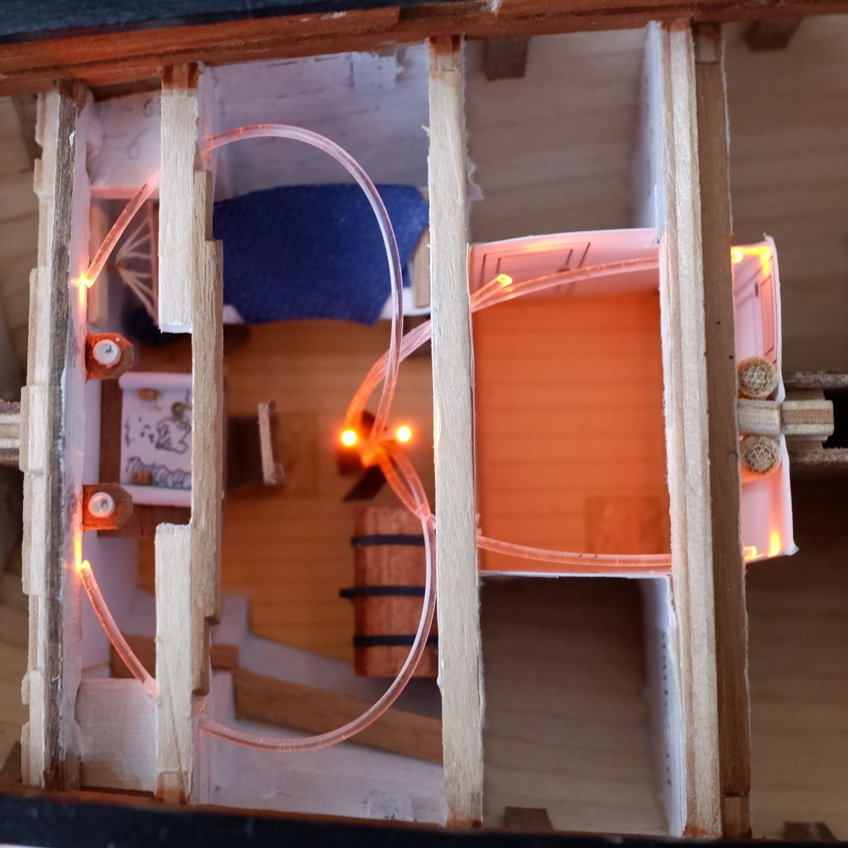
Richard, I have used optical fibres to light the interior of my 1805 schooner model in 1/64. The period and scale are quite different but optical fibres have properties that are useful or a pain, depending on what you are trying to achieve. One is that they leak light if you bend them too much so they have to be routed carefully. A second is that if you roughen the surface the light also leaks out. This might be what you need to simulate your fluorescent tubes. I have used 1mm diameter plastic fibre and arrange seven fibres in a hex pattern to face a 3mm diameter LED. The fibres enter the model through brass tube stands (3mm internal diameter) so they are invisible. This also leaves electronics and solder joints outside the model so they remain accessible. The fibres are readily available on Ebay and cheap so a bit of experimenting could give you a solution. George

-
It was a few years ago and I think that tiny rubber band came from a cocktail umbrella. We had bought a small box of them and each rubber band kept an umbrella closed. George
-
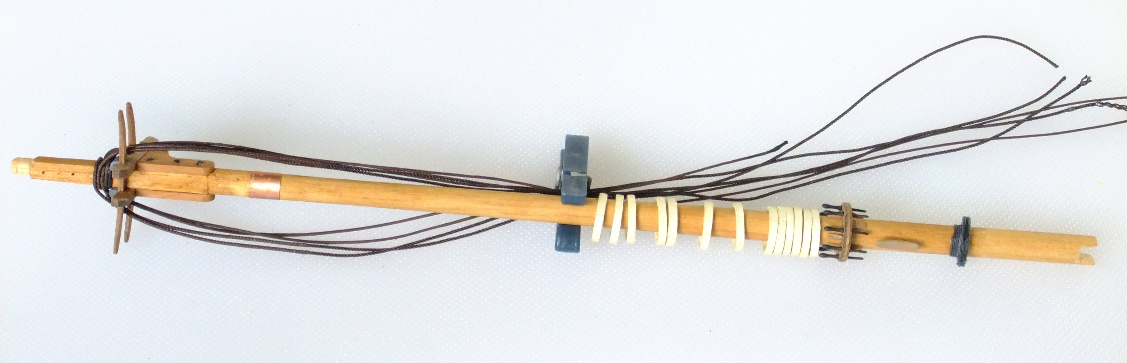
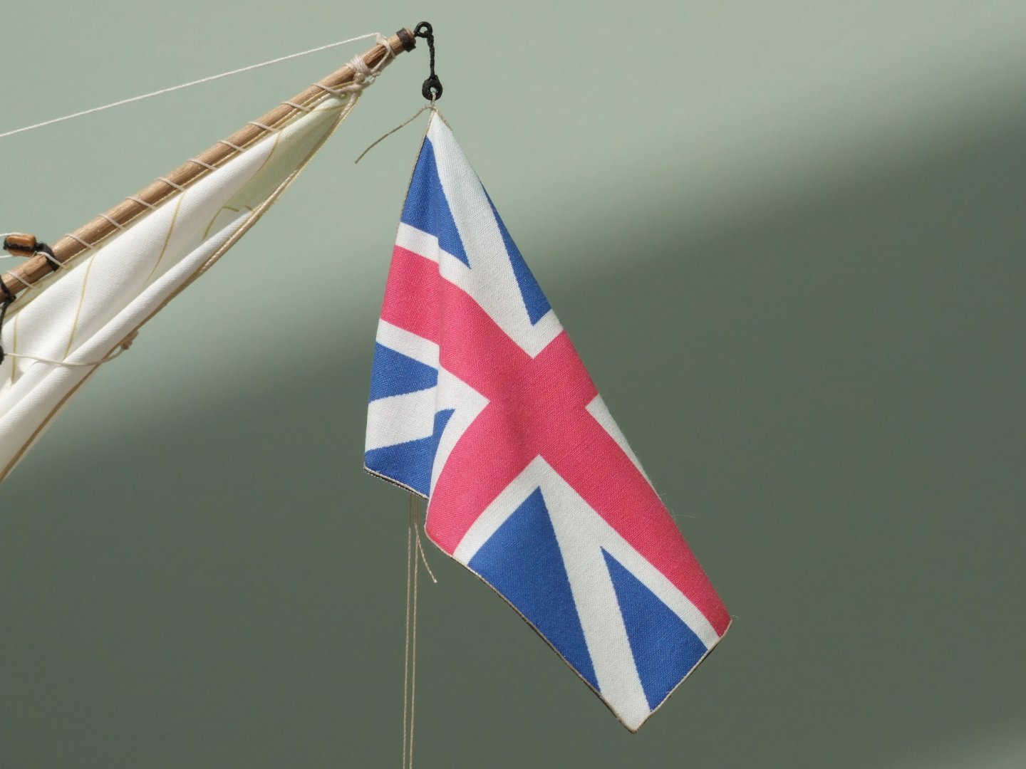
Phil, Congratulations on being on the final straight, it's just irritating that someone keeps moving the finishing line a bit farther away. You'll get to cross it some day soon. Anchor nun buoy. I made one for my Sherbourne cutter from plastic left-over bits. Think model aircraft drop tanks, bombs, pen tops, there are lots of things that take you along the way. The trickier part is to create the ropes and hoops that all go over each other. The attached pdf is about anchors and describes the buoy in more detail. Anchors.pdf The difficult question is where to store a buoy and its rope. Tying the buoy to the shrouds is reasonable though it would take several sailors to lift it while one ties the first knot. I cannot really imagine where else it could go on a schooner with cramped accommodation below. The rope from the buoy to the anchor is 17 to 18 fathoms (Lever page 68) which on your 1/48 model is well over two feet. That is a big, unwieldy coil to hoist up on the shrouds and then tie in place. Could the rope be kept in the cable tier and spliced or hitched on when needed? Flags. I spent time with a hand towel looking to see how it would hang. Hold it up by one corner and pull another corner so that a short edge hangs vertically. You can now play with folds in the towel/flag to bring forward the bits you want to show. The critical feature is that some of the flag (ideally 50%) falls forward of the halyard; if you want the flag to be fluttering to one side of the halyard then gravity will win and the short 'vertical' edge will hang at an angle unless you put on a scary amount of tension. I will be laser printing onto tissue (teabag paper) later this year when I start on the sails for Whiting. Like you, I am concerned that sticky tape will ruin the fuser in the printer if I have to attach the tissue to stiffer paper. A fall back method that I am considering is to glue the edge of the tissue with a glue stick (Pritt stick in UK). I don't know if anyone else has tried that here, or experimented with different tapes. You could run some trials with that small iron you use for bending planks. George
-
Phil, I understand your last post and agree that there are choices to make about the level of detail to include on a model. I also ignore trenails but others like to include them. I have copper plated the hull with Amati parts which have representations of nail holes because to my eye plain ones look as if something is missing. My most extreme inclusion is probably the furniture in the captain's cabin on Whiting which is only just visible through a skylight. Methods for serving a rope is something that I have been experimenting on and at present I rely on thick paint; I doubt if the turns of a serving line would be visible at normal viewing distance in 1/64. But if I make myself a serving machine then I might change my mind. To me a joy of the hobby and this forum is that people make their own choices and accept that others can follow different paths. George
-
Whats the best book on rigging for a beginner?
georgeband replied to Stuka's topic in Masting, rigging and sails
I bought a copy of Ashley's Book of Knots and really enjoy it, but it's not a beginner's book for modelling. Prices vary widely so look around before you buy. The Young Officer's Sheet Anchor by Darcy Lever is one that I recommend especially if you combine it with internet searches for specific knots and details. Facsimile copies of the 1800ish book are readily available or you can splash out on an original copy. It's a great introduction to knots and rigging and masts and sailing, and to the language of the time. It's inspirational and it pulled me into the world of ship modelling. George -
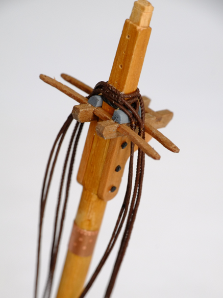
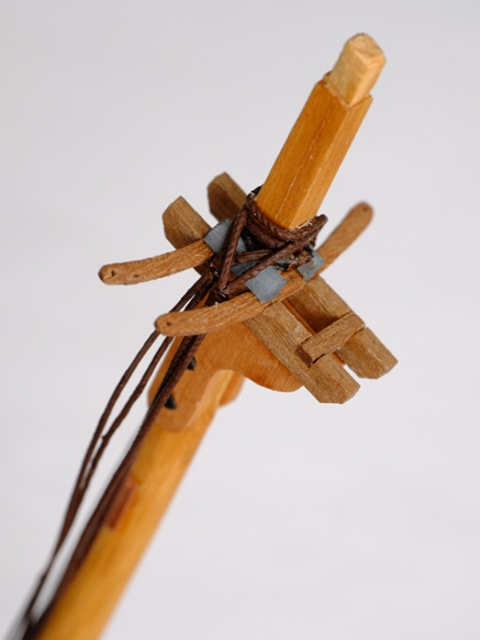
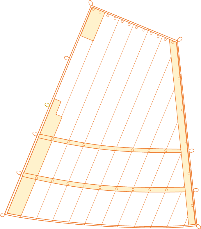
Shrouds fitted to fore mast The mispositioned shrouds came off the masthead with no problems at all and I re-used them starting from the aft end of the foremast. The first pair is a pendant and one shroud, both fully served by painting the linen thread, set to aft and starboard. Then follows a similar pair to port, then two forward pairs of shrouds to starboard then port. The final pairs use Ropes of Scale 0.6mm thread with the middle section painted to represent serving. The lay of the thread shows through the paint and I might give it a few more coats or learn to live with it. The pictures show the masthead from aft and starboard The holes in the back of the masthead were predrilled to take three eyes for blocks; the lowest of these is now covered by shroud ropes and I will probably put a new one between the two existing, exposed holes. So much for planning ahead and preparation. Sails Currently I have been drawing sails which is an iterative process with the yards from which they hang. The lengths of the yards are based on drawings for another schooner, but a sail is an integer number of cloths wide, and the distance from the top corners of the sail to the cleats at the end of the yard depends on which sail it is and the notes provided by Steel. So I start with a yard of nominal length and see what width of sail fits it best, then adjust the yard so that the sail sits properly on it. It gets more complicated for a gaff sail where the runs of cloth are not necessarily perpendicular to the yard and you can also adjust the angle of the gaff. Computers do make this step easier and I use Powerpoint simply because I am familiar with it from work. (Work is no longer a distraction for me 😁.) I know that there are better drawing packages available but I would have to climb another learning curve to use them. One other change I have to make to 'finished' tasks is about the number of hoops on a mast for a gaff sail. I had allowed for two hoops to each cloth in the sail which gives about a dozen for the fore and main gaff sails. Steel in his drawings of gaff sails shows one hoop per cloth so my preloaded mast has far too many hoops on it. They are easily removed with a snip and this is much easier than trying to fit more hoops on at this stage. The pictures below are the fore gaff sail and the completed lower section of the fore mast George

-
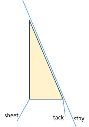
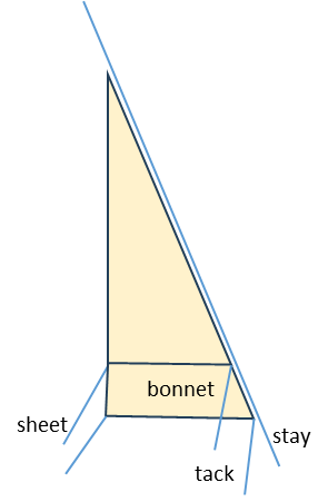
Thank you Trevor and Henry for your suggestions. I do like the idea of moving a sheet and tack from their cringles on the (short) sail to the cringles on the lower corners of the bonnet. Toggles would make it a quicker procedure. Darcy Lever discusses toggles on page 115 of The Young Sea Officer's Sheet Anchor and there are small illustrations on other pages too. He says that a cringle on the sail is made just large enough to pass the eye on the end of a rope through it. The toggle is then put through the eye. (My childhood experience with duffel coats was that the toggle was tied into the end of the rope. To use it the toggle was passed through the equivalent of a cringle and then turned 90 degrees to lock it. Obviously it did not follow naval practice from 200 years earlier.) As a further complication on a schooner, and probably a ship, a stay sail or jib had two sheets on it so that the windward one was slack and ready to be used after tacking. The 'eye at the end of the sheet' becomes an eye at the end of two sheets for the toggle to be inserted. I will be delighted if anyone has information on this detail but will make something reasonable if nothing surfaces. At 1/64 scale the fine structures of splicing and seizing soon disappear. George
-
A bonnet was an extension that was attached to the bottom edge of a sail to increase the area; a reef could only make the area smaller. Steel gives good descriptions of how they were made and how they were attached. This is enough information for me to make a stay sail with an attached bonnet, and I know from a sub-Lieutenant's log book that this was done on HMS Whiting. What I do not know is what happens with the sheet and tack at the bottom of the sail. The stay sail would have its original sheet and tack when it is without a bonnet. When the bonnet is attached it will also need a sheet and a tack otherwise it becomes a curtain that flaps in the breeze. Do both sheets belay to the same point, and similarly do both tacks belay to one point? Or do they belay to different points? Or do the original sheet and tack become redundant and are coiled and hung somewhere out of the way? Steel is silent on this topic unless I have missed it. Any assistance will be gratefully received. George


-
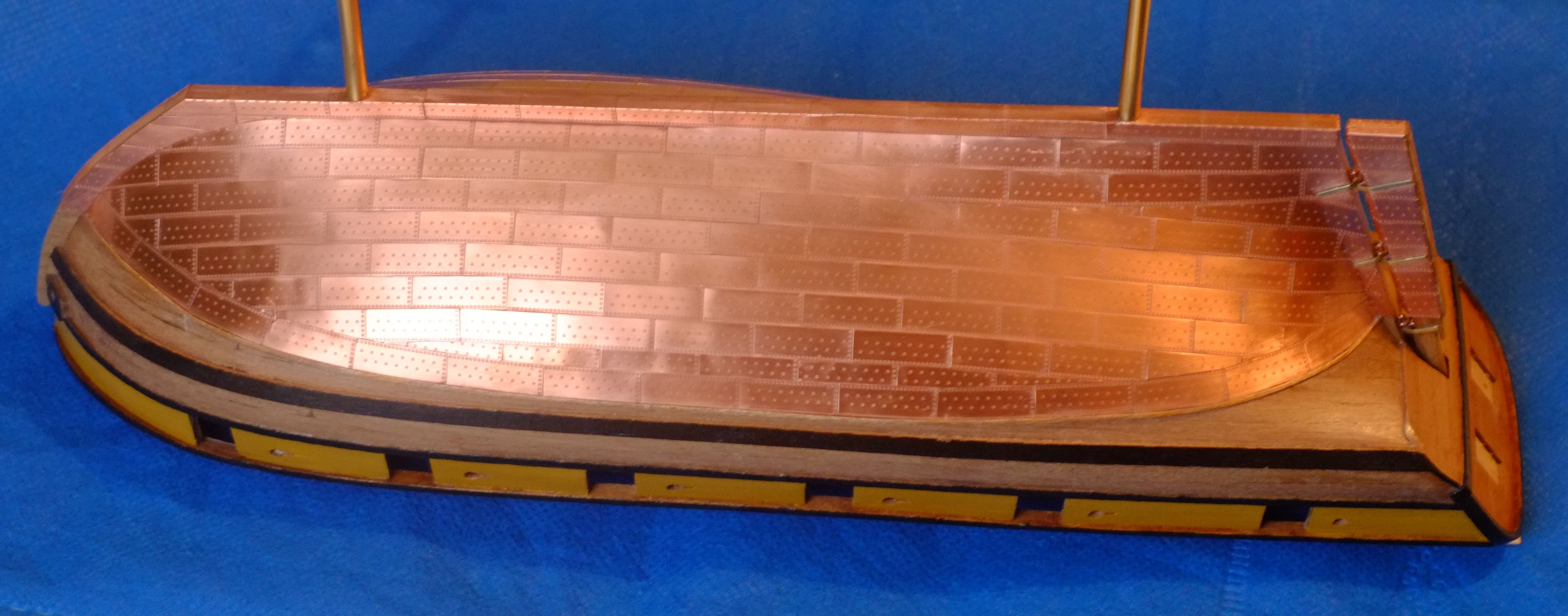
I plated my 1/64 model of HMS Whiting (Caldercraft Ballahou schooner) with Amati plates and it took me about 100 hours to finish the job. Apart from being a slow worker I trimmed the plates so that they did not overlap and betray the overscale thickness. It's a slow process. The picture below shows part of the stern, and a fingerprint to prove that I did it. There are a few narrow gaps between some plates but they are not visible at normal viewing distances. I used grade 0000 steel wool to clean the surface. It caught in a couple of places where a corner of a plate was slightly proud so remedial work with superglue was needed. I wanted to keep the copper shiny. Partly this is personal preference because I want to reflect lighting in the display case when it is finished. The other reason is that the copper remains shiny under the water; the brown or green patina requires air for it to develop. I chose Renaissance wax as mentioned above by RossR and applied it with a miniaturised version of the technique shown in the film Karate Kid - wax on, wax off. A couple of years later the copper is still bright. George

- 20 replies
-
- 3
-
-
- Indefatigable
- copper plates
- (and 1 more)
-
I have browsed through a downloaded copy of Steel's Masting and Rigging, 1794 edition, and he does provide corroboration for Marquardt. There is nothing specific for schooners but I looked at the main (aft) mast of a brig and the only mast of a cutter which have similar layouts to a schooner mast: gaff sail and no square sail. Pages 220 and 222 in Steel have the relevant entries and one states ‘The after-main-shroud must be served from the mast-head to the dead-eye, to prevent its being chafed by the main-boom and gaff.’ It seems that the model which Petersson used for his excellent book was not aware of this. I will be making changes to the fore mast when I get back home. In the meantime I have the slowest internet connection which is similar to the pace of life while on holiday. George
-
georgeband reacted to a post in a topic:
Albatros by Dr PR - FINISHED - Mantua - Scale 1:48 - Revenue Cutter kitbash about 1815
-
Tony, Phil, Thanks for your comments and information. It is a puzzle with incomplete evidence for either option. I'm off on holiday for a while (no grandchildren this time) and will ponder the alternatives over a glass of something fizzy. Perhaps someone else will join in with a definitive answer George