HOLIDAY DONATION DRIVE - SUPPORT MSW - DO YOUR PART TO KEEP THIS GREAT FORUM GOING! (Only 36 donations so far out of 49,000 members - C'mon guys!)
×

Kenchington
-
Posts
679 -
Joined
-
Last visited
Content Type
Profiles
Forums
Gallery
Events
Everything posted by Kenchington
-
 @tmj, The easiest and cheapest place to get rid of ballast, before taking on cargo, was almost always on the harbour bottom under your ship's keel. As @wefalck has noted, the authorities in the various port towns tended to take a dim view of having their harbours silted up like that -- though a town on a fast-flowing river might not be concerned, while ports with deep anchorages had little to worry about. For the next ship needing ballast, however, the seabed was not necessarily the cheapest place to find it. I think (but am not certain) that I can recall some ports having specific ballast grounds, where a ship would be moved when dumping ballast and where other people, perhaps specialized suppliers, would go dredging for suitable gravel -- which would be conveniently washed in the dredge on the way up. Whether that was done in the times and places where cogs were used is more than I can say. Labour costs for ballasting could be low to zero, if the ship's crew had little other work to do while lying at anchor awaiting cargo. However, the overall costs of ballasting were high enough to encourage hull-shapes that could be sailed with neither cargo nor ballast or at least with little of the latter. And, much later, water ballast carried in the double bottoms of iron and steel ships was a big cost saving. All of which is to say that ballasting was a complex business, varying with time, place and trade, amongst much else! Trevor
 -
The full-size practice that I am familiar with has an eye splice in each end of each ratline, with a seizing to fasten each splice to the appropriate shroud. And that's definitely too finicky at typical model scales! But I fully agree that the pointy projections that glued clove hitches produce look wrong, while model ratlines are usually made of out-of-scale material. But fixing those still leaves another issue. So, before I have to face the problem myself, I'll ask: Has anyone found a practical way to get ratlines to hang in dozens of little catenaries? Bar taut doesn't look right to my eye but upward or outward curls are far worse! Trevor
-
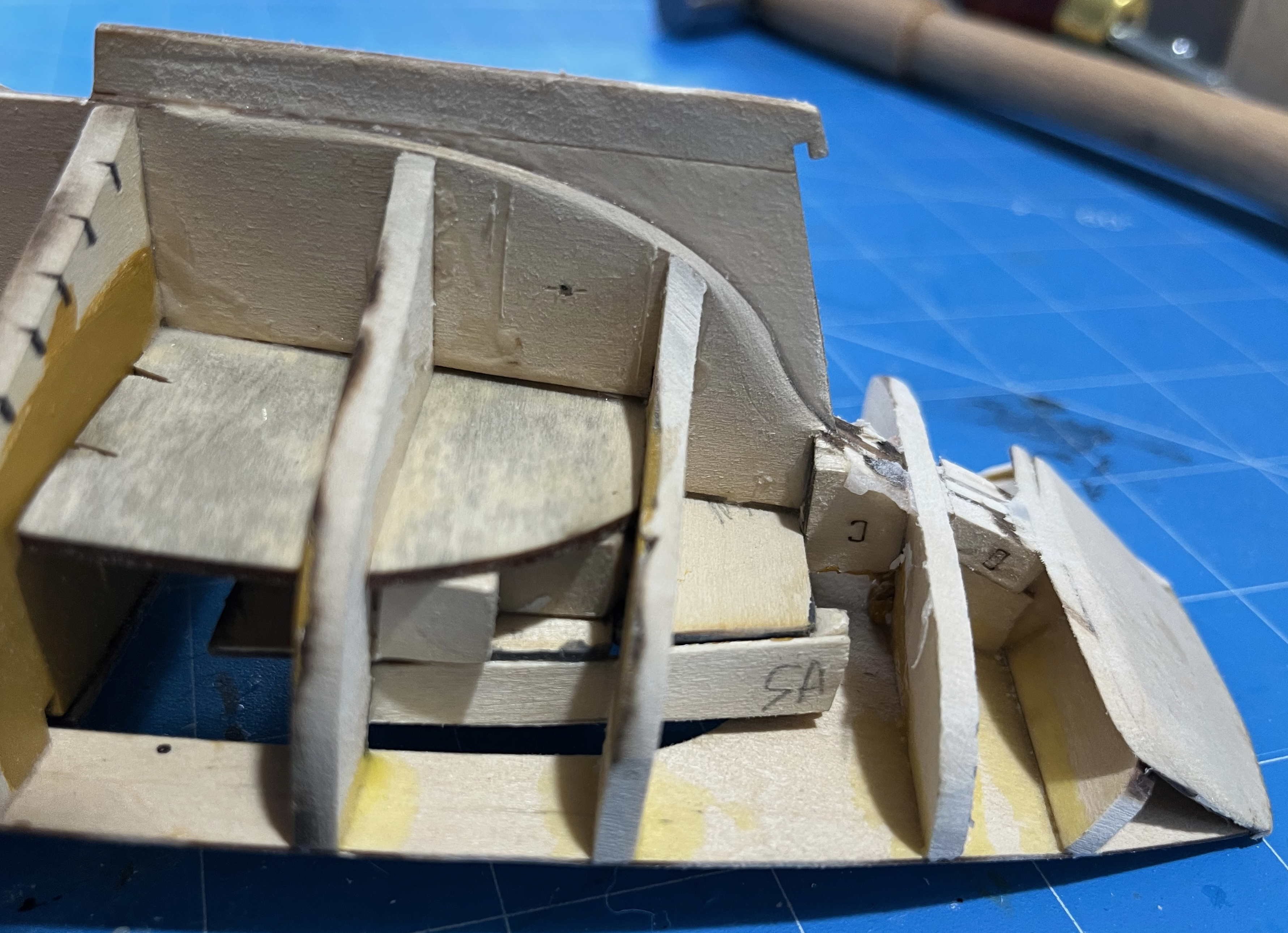
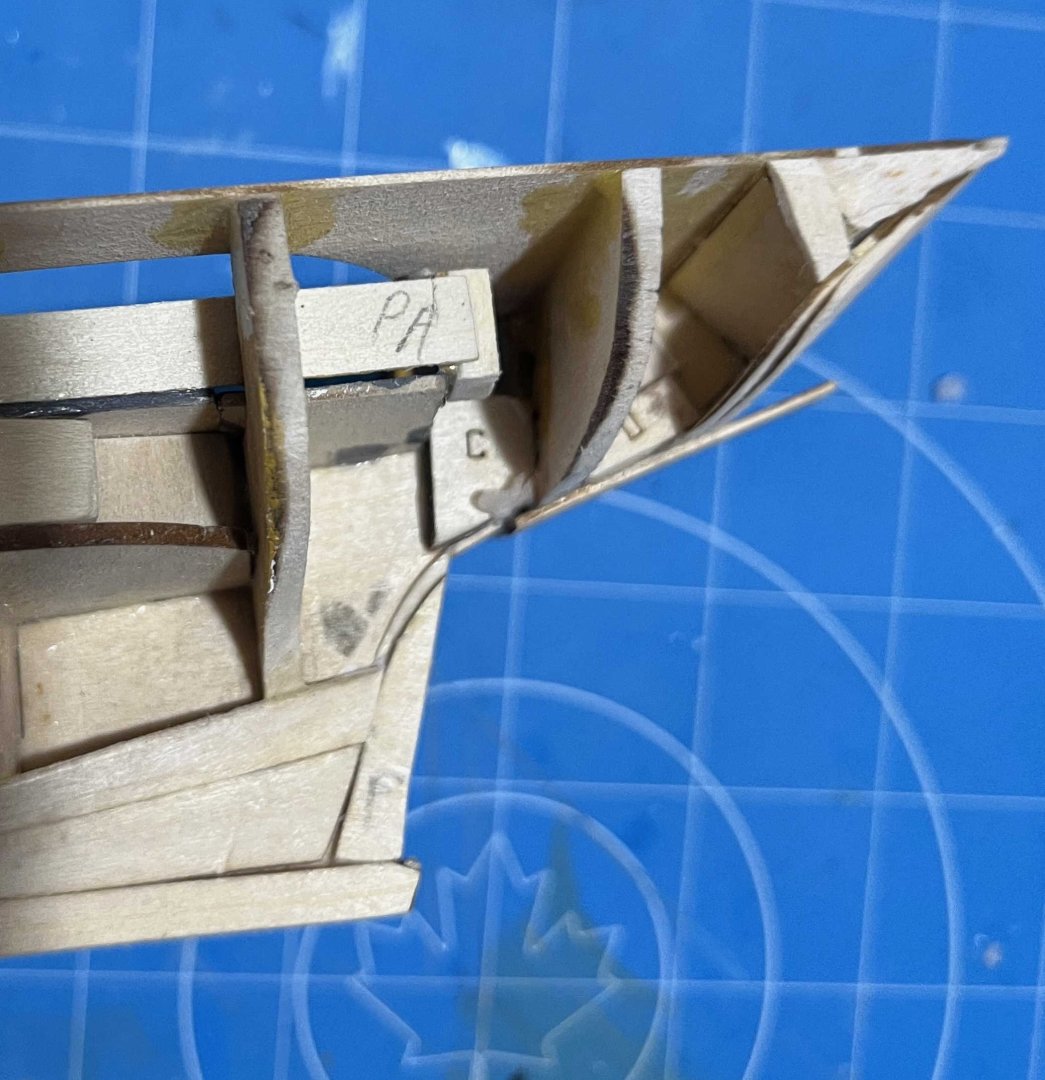
Progress did not slow today, to my surprise, and Strake 8 is in place. I hope to have Strake 9 bent and drying overnight, though that's not done yet. However, I did have a major problem, from a silly mistake: I had cleaned the char off the port-side Strake 8 and was giving its flat faces a quick wipe with a very fine-grade sanding stick -- when a third of its length simply broke away and shot to the floor! I can't see a weakness in the wood, so I must have become too casual and pressed too hard. My first thought was a repair, with a butt strap for strength, but that would have made a hard point, altering the bend of the strake. So I made a new one from scrap, using the original strake's slot in the basswood sheet as a template, then cutting and sanding. I clamped the broken parts to the new and sanded until their edges were flush, then finished by ensuring that the new piece matched the starboard-side strake. (I figured that an exact match, starboard to port, was more critical than an exact match to the kit's spiling, though any deviation was very small anyway.) So planking continues, as does the emergence of a hollow between Bulkheads 8 and 9, either side of the sternpost. I'm blaming that on the need to re-attach the snapped-off after skeleton, though insufficient fairing of Bulkhead 8 may have contributed. More tomorrow, Trevor
-
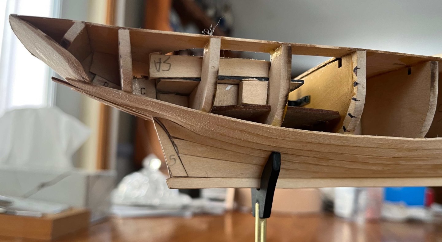
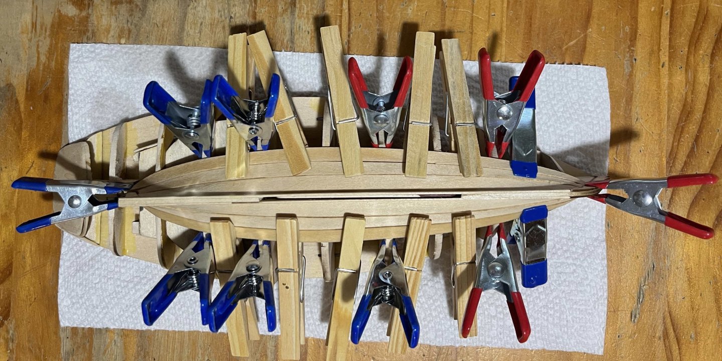
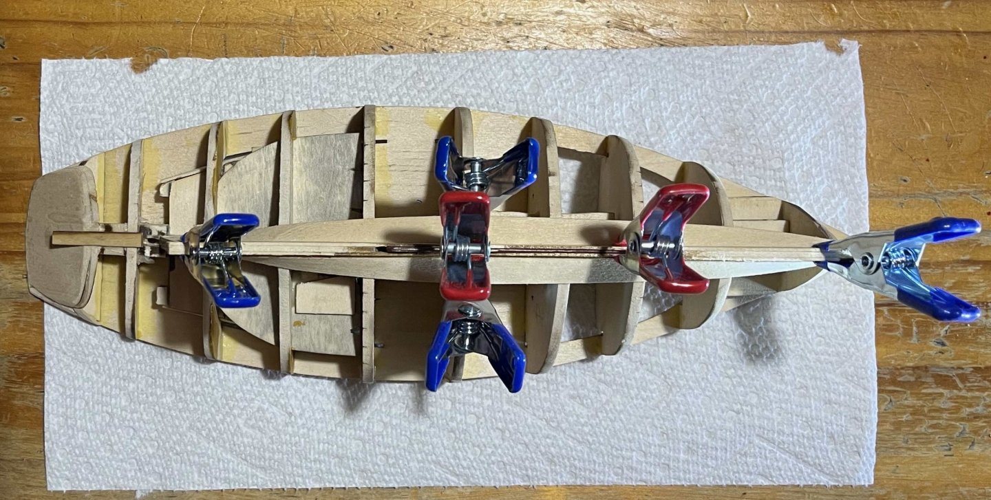
With Strake 5 in place, she looked like: Since that stage, I have added Strake 6 and have Strake 7 drying overnight. This beginning to feel like a routine, while probably means that I am about to make a major, silly mistake! Progress may slow down from here as I do not have enough small spring clamps to handle the planks on both sides at the same time. Trevor
-
John has said how he came to knowledge of the last generation of big square-riggers. For the rest of us, much information is readily available as those ships were particularly well documented -- partly because they were still in active use when historians began to get involved with nautical technology, while people involved in the business (Lloyd's underwriters, as much as Masters and owners) were aware that they were seeing the end of deepwater commercial sail, hence felt an incentive to record everything. Then, of course, handheld cameras (even movie cameras) were becoming available. Equally important, beginning with Basil Lubbock, some young men (and at least one young woman) with good educations chose to experience merchant sail before it was lost -- after many generations when European gentlemen might become navy officers but most definitely _not_ merchant seamen. (The USA was a bit different, as in the case of Richard Henry Dana.) Hence, we have descriptions of the ships and life aboard them from people who could write and who saw their new world with an outsider's eyes. Alan Villiers, Eric Newby and several others contributed to that literature. The Duchess was especially notable in her day, having been built as a smart cadet ship, and was consequently well recorded. Derby's "The Tall Ships Pass" has many photos taken aboard her. Trevor
-
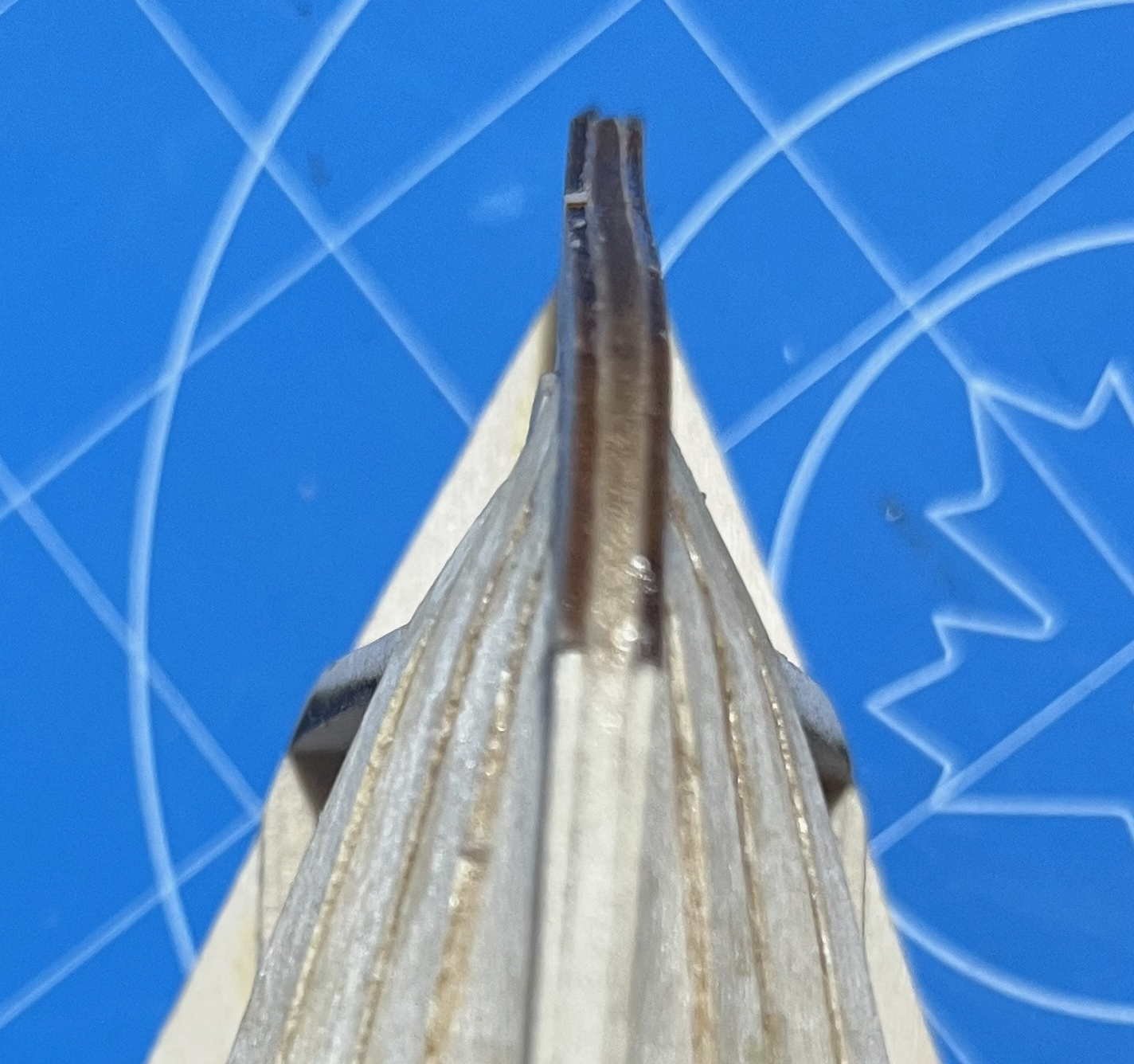
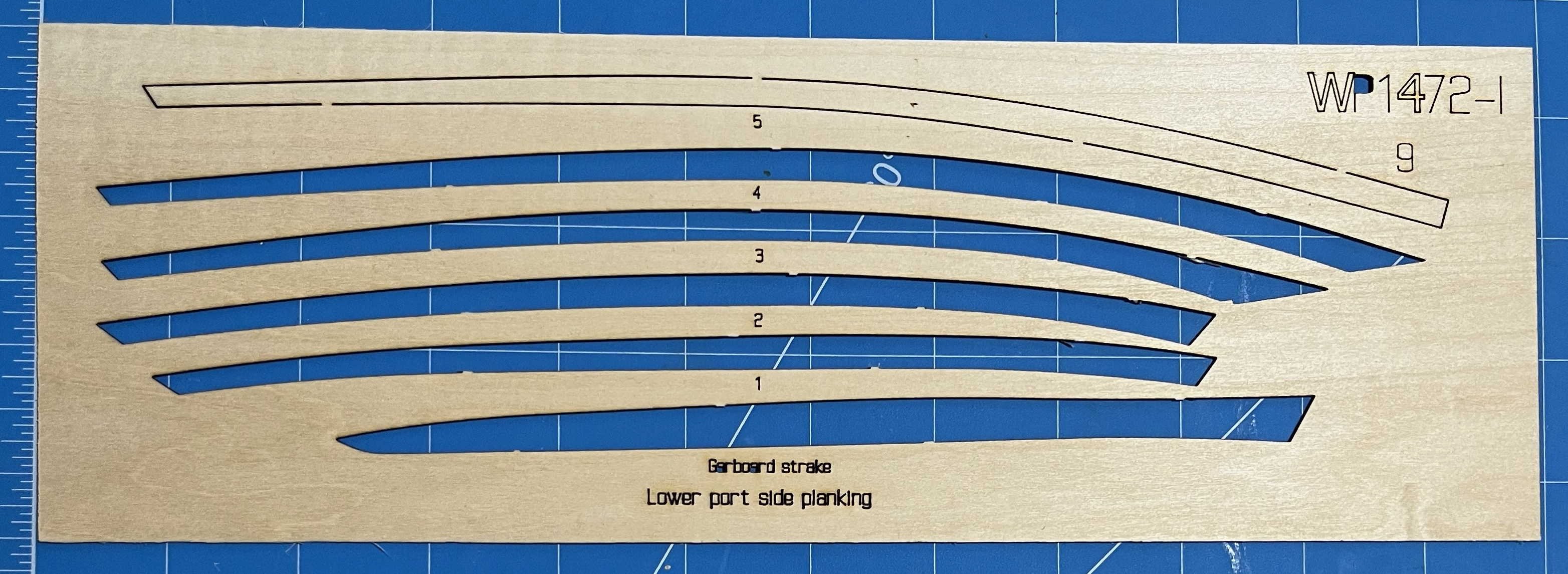
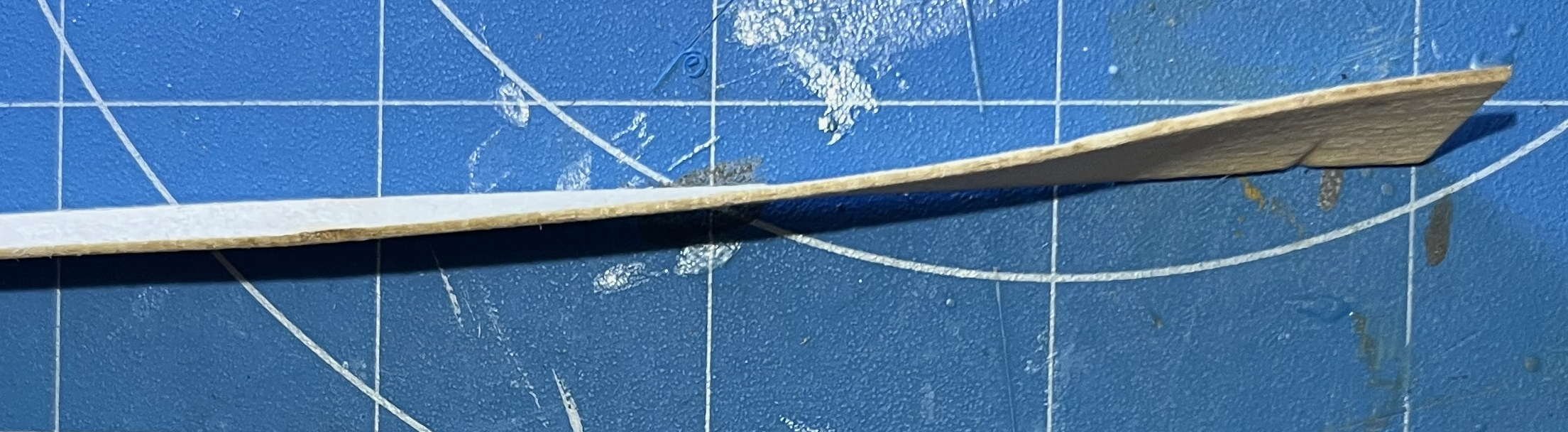
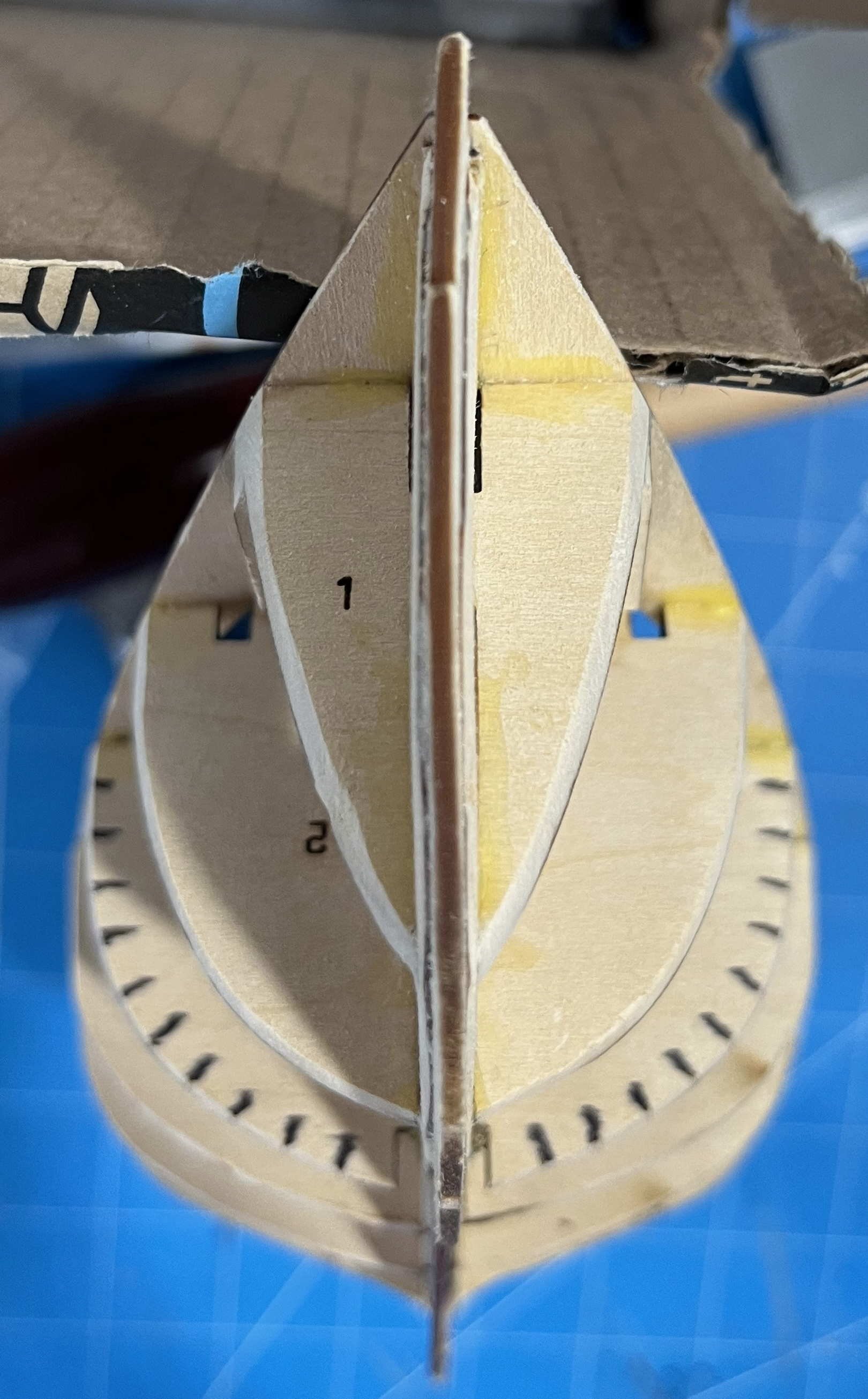
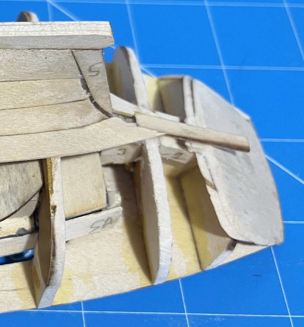
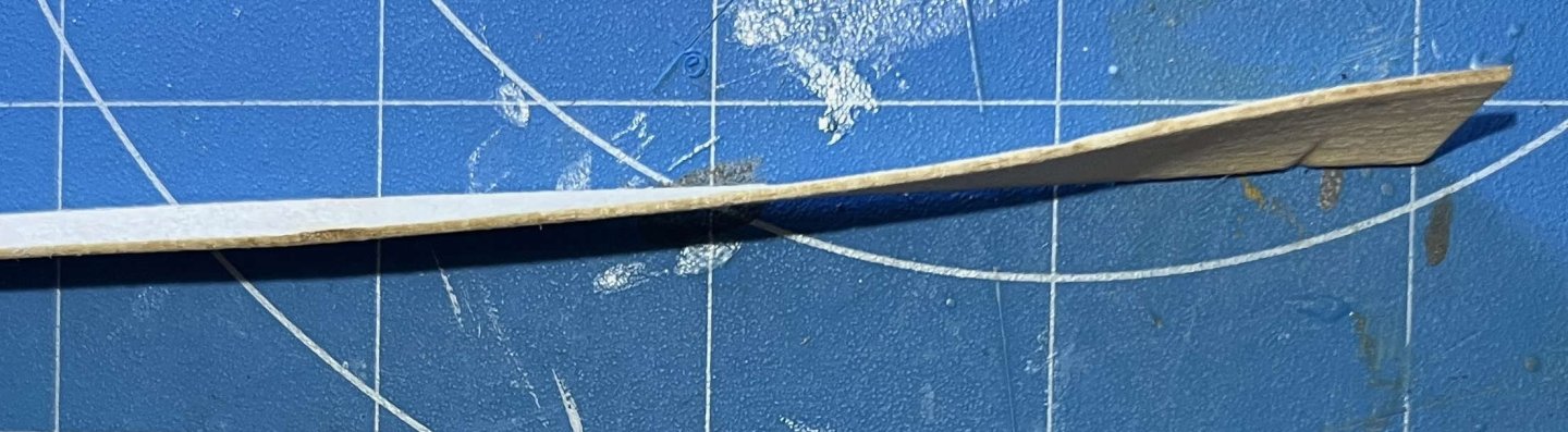
Added Strake 5 this morning. With the garboard, that makes a total of 6 out of the 11 strakes, so I am half-way through the planking and beginning get tidy outcomes. One unwanted hollow has emerged immediately abaft the sternpost, whether because I faired Bulkhead 9 badly or as a result of my having to reconstruct the model's skeleton in that area following damage, I cannot tell. That aside, it has been remarkable how easily everything has fallen into place, with only minor errors on my part. The strake edges are falling a little short of the tick marks on the bulkheads but consistently so. The kit is designed with extra width in the steerstrake. I can only hope that it will be wide enough! No images from today's work yet but I do want to illustrate two points that I made earlier. First, the excess fullness of Bulkhead 1, low down towards the keel: Note the curvature as the strakes cross the bulkhead, causing them to meet the stem at a blunter angle than the deck does, whereas they should be sharper if anything. It is not a problem seen with the higher strakes. On the positive side, the spiling of the kit's planks is almost unbelievably well done. Consider Strake 3. That came out of the fourth space in this basswood sheet (the one with the little notch for the sternpost, in the strake's bottom-right corner): A nice, smooth, flat curve, albeit of varying width. Yet, once bent and glued in place, it looks like: That's an S-bend in side view, superimposed on a twist of about 45°! My attempt to construct it in 3D will need some filler to hide the mistakes but the fact that I could make it at all comes down to the quality of the kit. And that's all to the credit of David A. and his spiling. Wow! Trevor


-
Another general consideration is the difference between permanent and temporary ballast. Vessels that don't have major changes in the weights on board (e.g. fishing craft) get "permanent" ballast that stays in place all season. Dense rocks are good. Vessels that carry cargo may need temporary ballast if the paying load isn't enough for stability under sail. Then sand or gravel is best, as it is easier to load and discharge, though a major consideration becomes the cost of material that will be dumped at the end of the voyage -- unless there is some market where it can be sold. Given the shape of a cog's hull, I would guess (no more than that) that they rarely carried much permanent ballast. As to well rounded, wave-washed beach-rock versus angular, ice-shattered field stone: It need not be an either/or. As a generality, large, rounded pieces could be locked in place with smaller, angular ones -- depending on what was readily available locally. For the specifics of cogs, try searching scholar.google (https://scholar.google.ca from here) with the two search terms "cog" and "ballast". That gives me 6,000 hits. Not all concern the intended meaning of "cog" but the first few include a study of ballast sand in Wismar Harbour, two reports on the Bremen cog and a Mariner's Mirror paper in cargo handling in cogs. Trevor
-
Limitation or challenge? It is all a learning experience, after all! Anyway, we get to work with easily bent basswood (not pine, let alone oak), and the hood ends don't need to have strong, watertight seating in the rabbets. For me, this is a first opportunity to see a carvel-construction hull come together -- something I have read about for decades (and sometimes written about too) but never had happen under my own hands. I'm not complaining about the challenges! Trevor
-
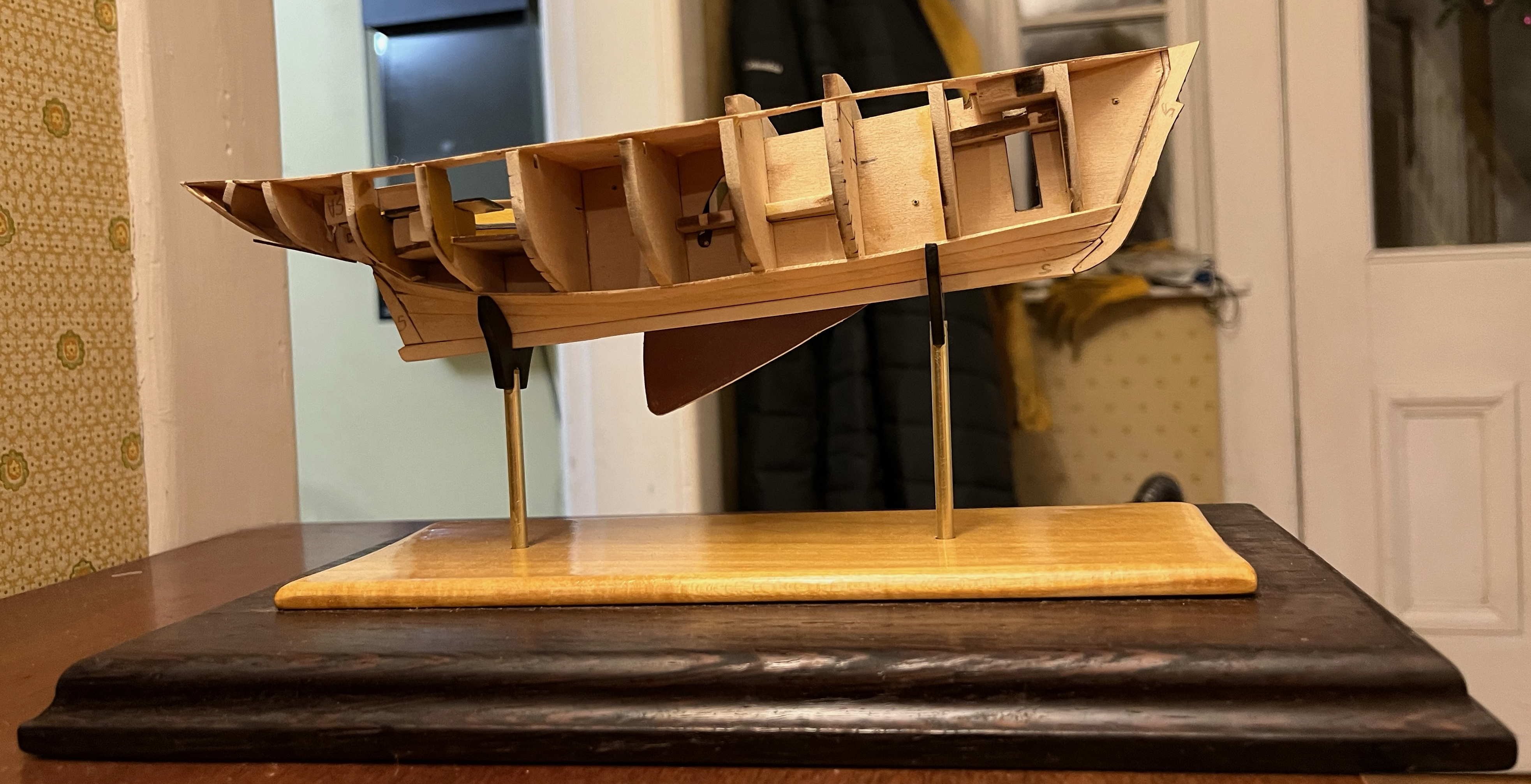
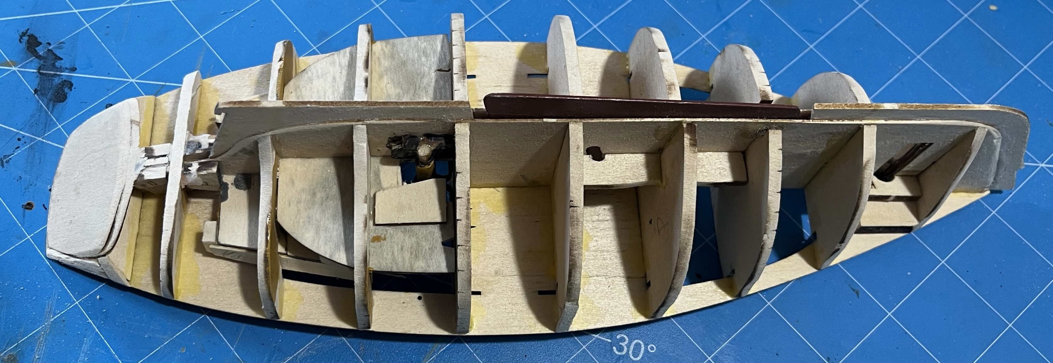
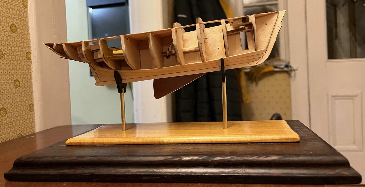
Strake 2 in place now. For its drying, I added pegs to keep it even with the edge of Strake 1, in addition to the clips on the bulkheads that hold the two strakes together: That seemed to help the final fit, so I am learning as I go! It will still need filler and sanding, and I will have to do better when I get to the NRG half-hull, but all should be fine for this little sloop once painted. With three strakes in place, the model can sit on its stand, so it is beginning to show its final shape: I may have over-done the extra height in those pillars but they could readily be shortened, if that looks desirable in the end. Two things I would have done differently, if I had known in time: First, Bulkhead 1 is too full down near the keel. It's not so bad as to be noticeable without a close look but the planks leave the stem at a wide angle, then bend too sharply as they pass the bulkhead. A bit more removal of material during fairing would give the hull a sweeter line near its forefoot. Still, nothing to worry about: A more important point, for any future builder of the kit wanting to learn from my mistakes: The instructions call for the garboard to be fitted starting at the stem and working aft, whereas Strake 3 is to be fitted around the sternpost and then working forwards. Both make every sense but I continued the stem-to-stern route for Strakes 1 & 2. For Strake 1, that was probably OK. However, Strake 2 needs a curved hood end, to match the shape of the rabbet in the sternpost and that would have much better been done before working forwards. As it is, I have a mess to hide with filler -- not so bad on the starboard side: but worse to port. Nothing that can't be fixed but I would prefer to have got it right the first time! I have pressed on as fast as soaking Strake 3 and clamping both starboard and port sides to the hull for drying. However, they will need trimming to fit against the centreline plank abaft the rudder port and I fear that they will need re-wetting and a second drying before gluing. I'll likely only be able to get that one strake on tomorrow. And then I hit an odd problem: I had fit the centreboard control rod as the deck went on, figuring that the narrow slot between the deck halves would keep the rod in place in its hole in the board. But, as I twisted and turned, fitting Strake 3 for drying, the rod fell out 😧 It was not hard to fit it again, with only three strakes then in place on the port side, but I will have to add a bit of scrap between two bulkheads to prevent it coming loose again. That is for tomorrow. Trevor

-
My hippos came from my wife, who picked them up while at a business meeting in Namibia. I'm not sure why she rejected them (too much potamous and not enough hippo for a horsewoman?) but they passed to my shelves instead. If you and I ever get to meet in person, they can migrate to join your herd. I dare say they would welcome the company of their own kind! Trevor
-
Step 12: Strake 1 (first above the garboard) fitted. Planking proceeded as smoothly as yesterday, with Strake 1 (which had dried overnight) going into place without much problem. I used a dab of yellow glue on each bulkhead, white glue in the rabbets and between the strakes. I started by fitting the forward end (as per the instructions), reaching back across three bulkheads and held by finger pressure without clamps. Then I did the length across two more bulkheads and then another two, before trimming the after end of the plank to meet the sternpost rabbet. Finally glued to Bulkhead 8 and the rabbet, then repeated on the other side of the hull: I also trimmed and re-shaped the centreboard (see the angle cut off, tucked in the corner of the above image). Perhaps because of the way I fixed the issue of the pivot position and the slot of the control rod, the board did not fully retract into its trunk. That is not really an issue for a model but it would be annoying in the full-size boat, as a protruding centreboard would mean that she couldn't be easily hauled ashore for maintenance. (At the least, it would need blocks placed to keep the weight off the board.) I waited to do the trimming until I had the garboards in place to add support to the sides of the centreboard slot, but did the job before adding Strake 1. Retracting the board also meant that I could square up the bottom face off the keel. The fit of the two strakes done so far isn't perfect, though nothing that a touch of filler in the rabbets and a gentle sanding elsewhere won't fix: I am now giving the glue time to set thoroughly before wetting and fitting Strake 2. Hopefully, I will get that dry and glued on with time enough to have Strake 3 shaped and drying overnight. Trevor


-
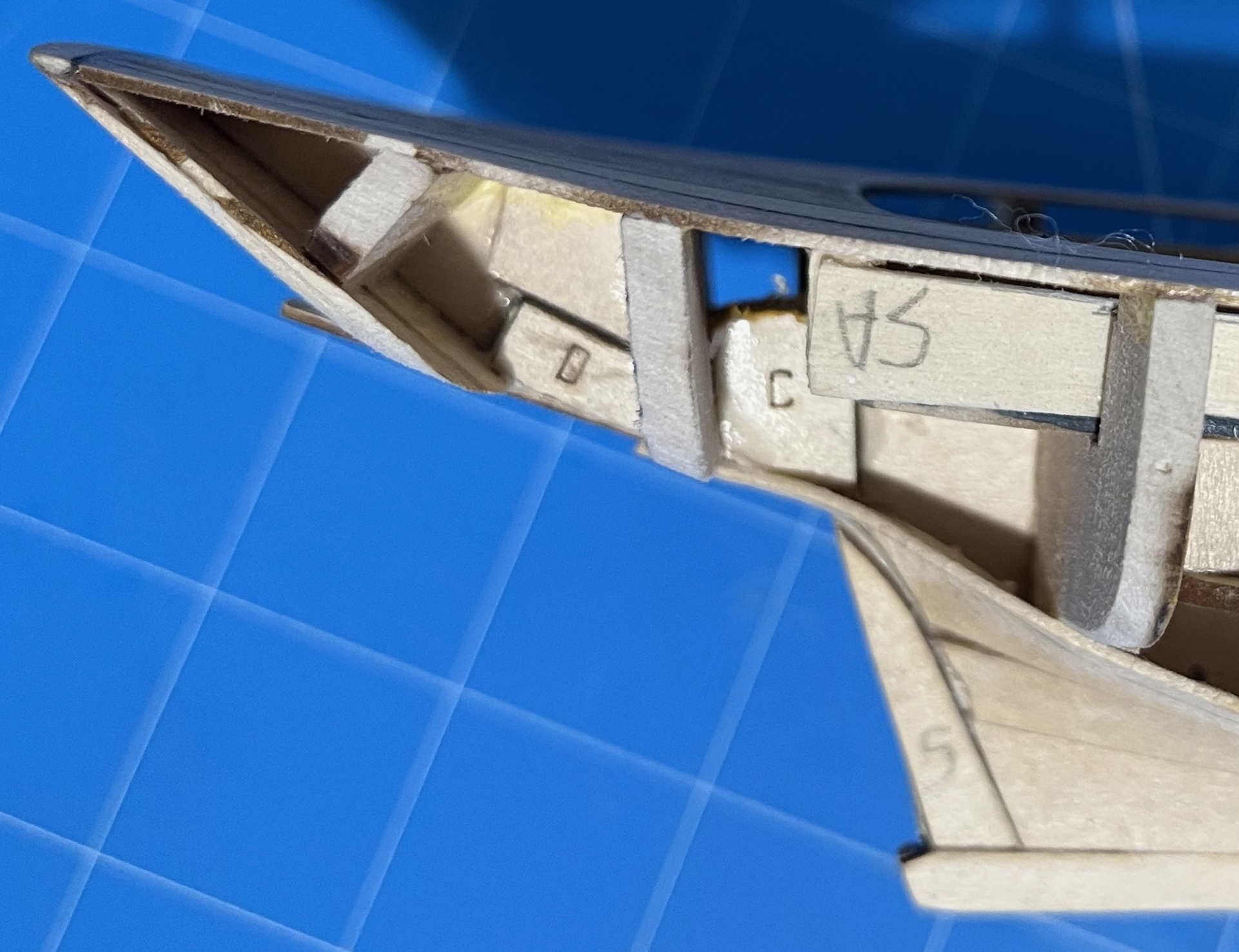
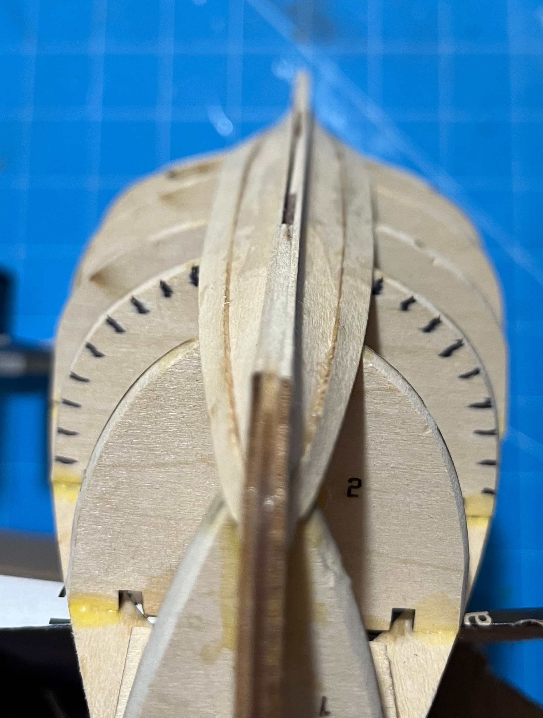
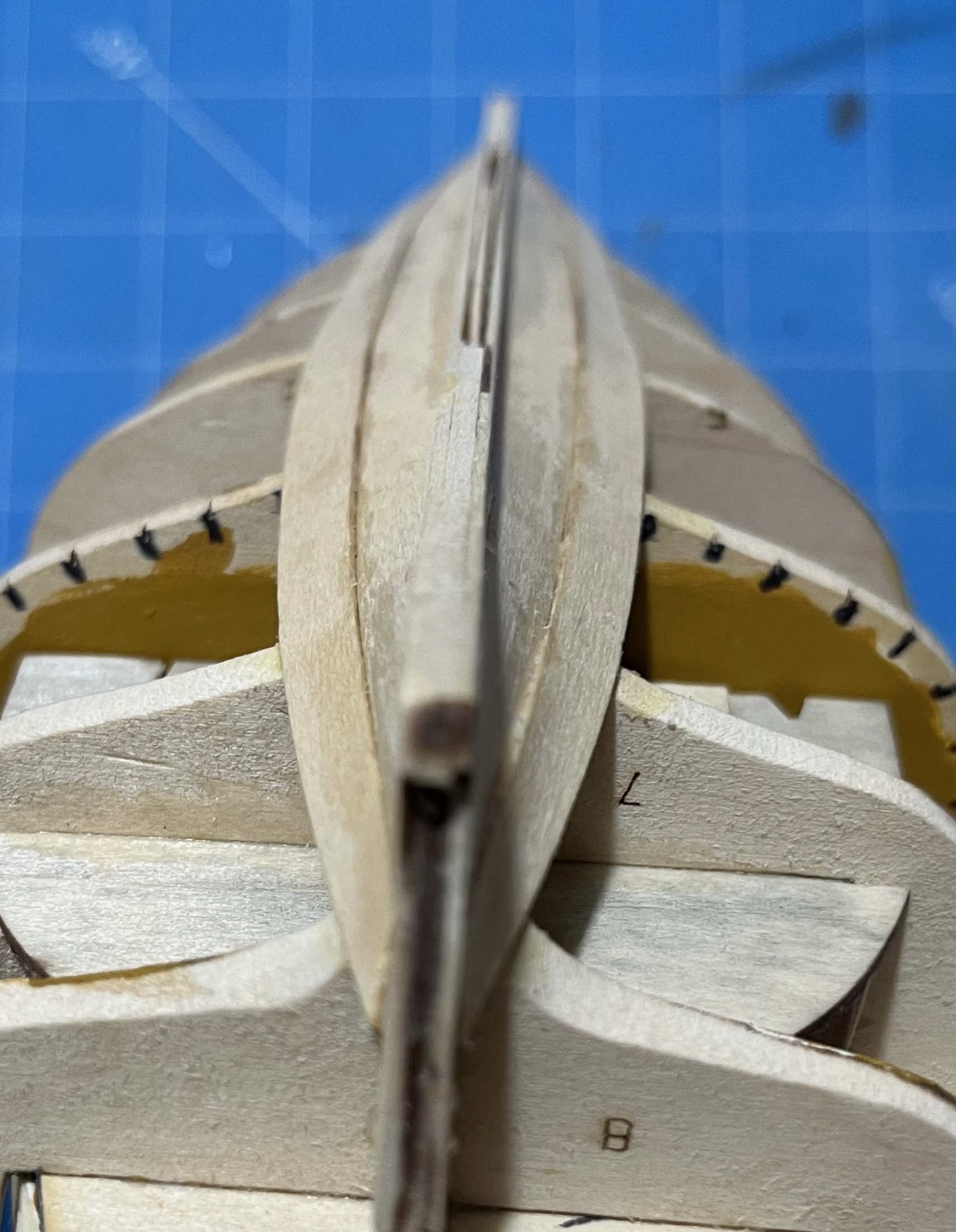
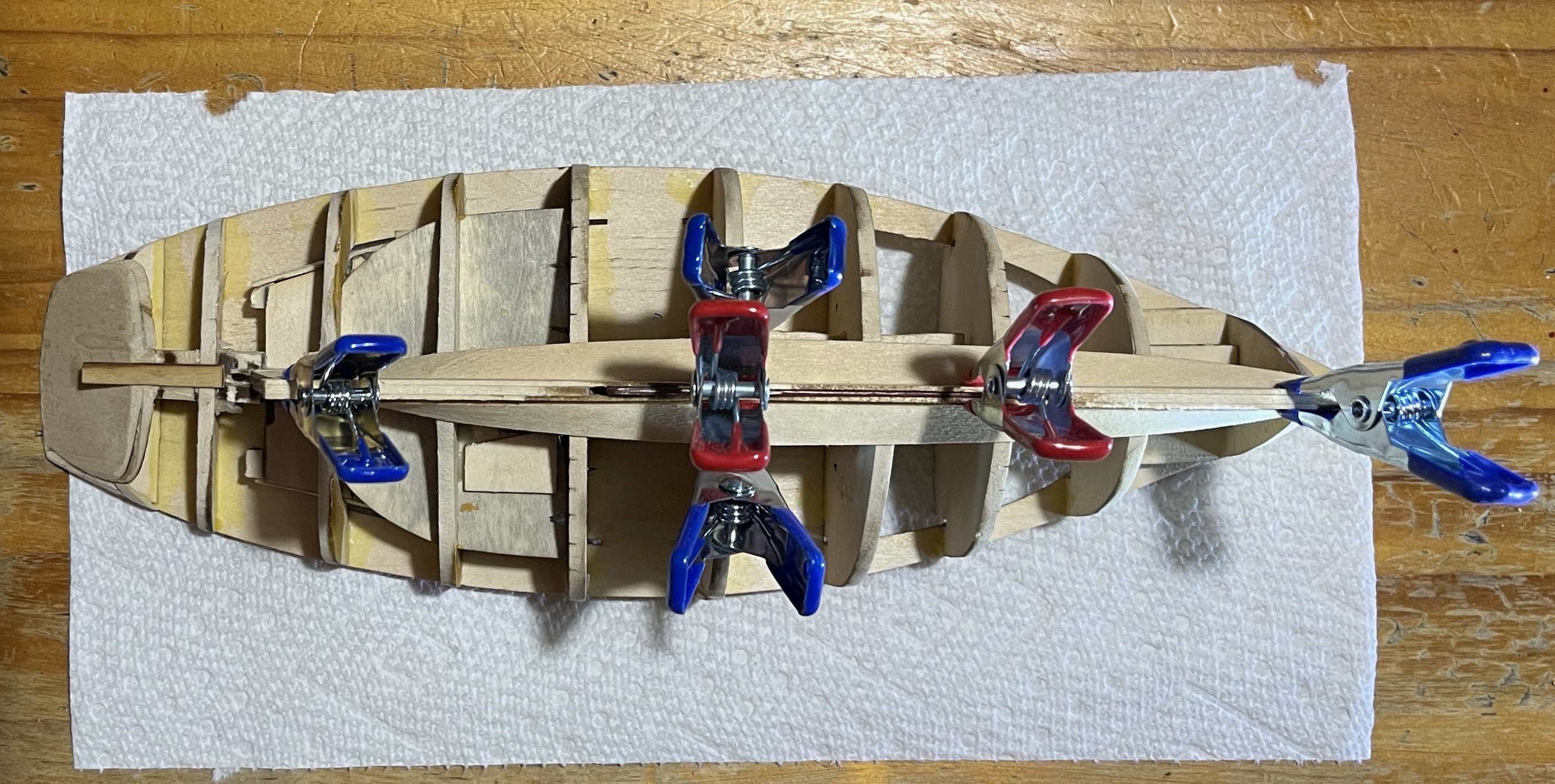
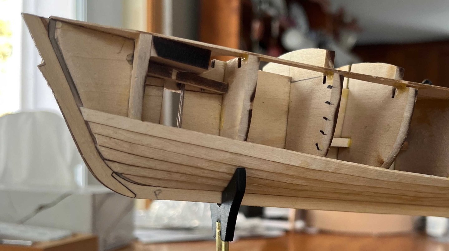
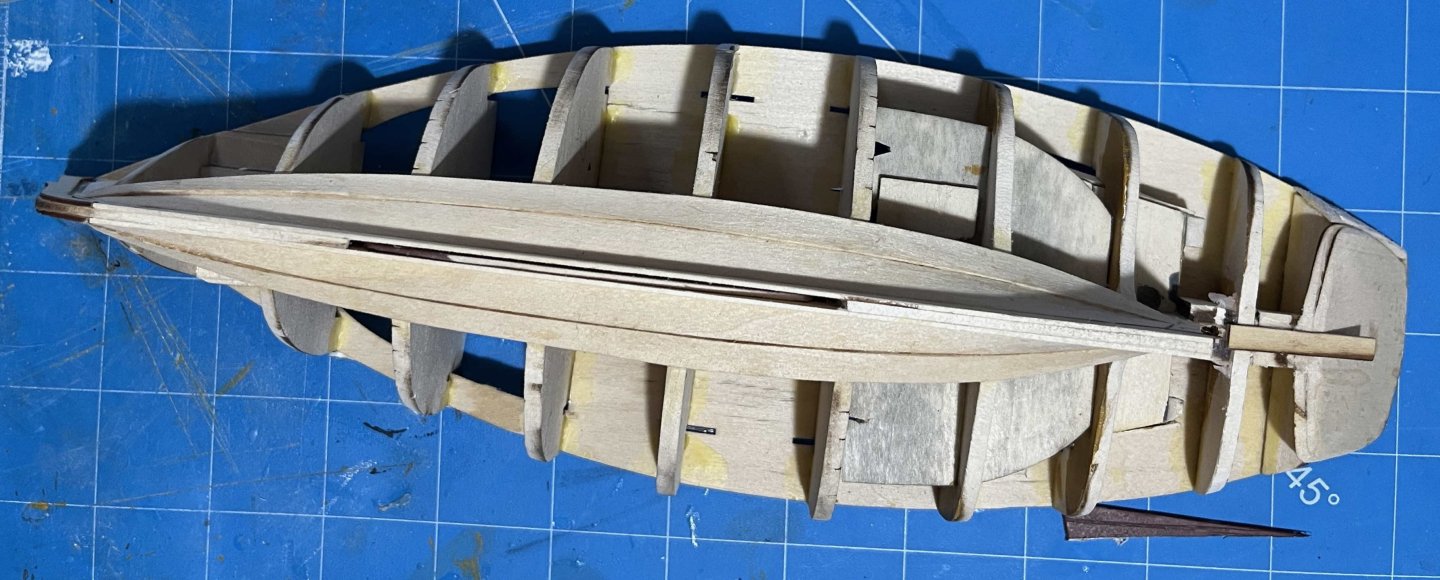
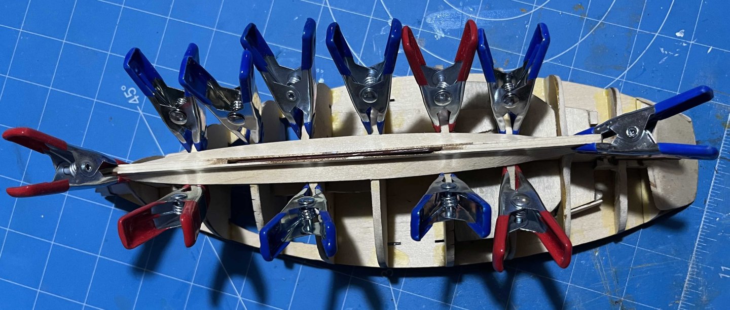
Steps 10 & 11 completed: Garboards in! The three-layered spine of the model has only its outer layers full-length, the central layer being broken for the centreboard and the rudder shaft. However, only the central layer reaches down to the bottom of the keel, forward to the cutwater and aft to the outer edge of the sternpost. The corresponding parts of the outer spine layers get added in Step 10 of the instructions, leaving a narrow gap which serves as the rabbets for the planks. Each of starboard and port, there are three pieces, forming the edges of stem, keel and post respectively. There is also a plank-thick spacer piece to help check that the rabbet is properly sized. All that went together very easily, except that dry-fitting the keel pieces showed that one bulkhead needed more fairing to create enough space for the garboards. While doing that, I thought of another check: I traced the edge of a bulkhead onto a piece of card held against the spine, cut around my pencil line, reversed the card and checked the other side of the bulkhead for symmetry. Several of the bulkheads are too encumbered with bits and pieces for that to work, while asymmetry amidships won't be very noticeable. But I did check Bulkheads 1, 2, 3 and 8, finding that they were all so close to symmetrical that I could not be sure to find the deviations. With that, it was time to get out and clean up the garboards, give each one 5 minutes in freshly boiled water and then shape it into place. I have noted before that this kit has the challenges of being of single-plank construction and having some complex curves. On the positive side, David Antscherl has done all of the laying out and splining for us, so the task should mostly be simple fitting of laser-cut pieces. The starboard garboard certainly went on very easily and smoothly, so I added the port one and allowed them to dry together: They have to take up a very pronounced twist in the run: but the wet basswood is forgiving and took the required shape without trouble. Both garboards then fell into place almost naturally, with glue to keep them there: The forward end of one garboard did rise a little in its rabbet but not enough to be worth ungluing. Also, one of the planks rose a bit free of one bulkhead and needed gluing back down, with a rubber band and Lego blocks to maintain pressure. Otherwise, all was well and the shape of the garboards is lovely -- a credit to David's planking skills more than to my fitting of the pieces. No photographs yet, but I have pressed ahead and have the next strake drying overnight, ready for proper fitting in the morning. Trevor Trevor
-
Hi Mark, It is good to hear that someone is finally working on a serious account of the ship, based on documentary sources. I look forward to seeing your book, once you have it ready, as the documents may be available to a keen student of the ship but not to one on the wrong side of the Atlantic! I will happily leave you to probe the details and present your conclusions. I have retained some doubt that the work undertaken in 1651–52 was entirely as recommended by the shipwrights, though that was what they were instructed (on 7 November '51) to do. You have now said that she was not docked that winter, which would have precluded most underwater repairs, but she was not ready for sea until July or August '52, which gave ample time (8 or 9 months) for the above-water modifications. Unless you have other documentation showing that that was not done, I don't think that the lack of a docking shows that major changes were not made. On the two rebuildings, we will have to agree to disagree until you have prepared and published your arguments. The principal dimensions (length on keel, breadth, depth in hold) were maintained, as multiple documents confirm, but the shape of the post-1660 hull was quite different to that of the ship launched in 1637 -- as is well shown by the artworks depicting each of them. The post-1685 ship retained the shape of her predecessor (aside perhaps from details of the stern) but, as you quoted above, had almost all new timber. Those were rebuildings, in the terminology of the time. I am interested in the quote you give of her number of guns and her ports being as in 1638. Yet both cannot be true as the old ship had an all-round (not broadside) armament, with multiple chase guns fore and aft. I do not doubt that the post-1685 ship carried 102 or 104 guns (whichever you prefer for the 1638 armament), as 100 was the normal number for a First Rate by the end of the century. But it would have needed another 9 on each broadside. Could the meaning of the document be that the number of ports on each of the three continuous decks was the same in the 1638 and 1685 configurations, while there were more ports on forecastle and aftercastle? Certainly, the types of guns were quite different. And, yes, I do know the derivation of "deadeyes", but that was clearly not what Boteler meant when describing "horses". Finally, Manwaring did indeed refer to the same "horses" as Boteler -- and he used that same term for them (as well as giving the latter's alternative meanings for the word). He even called the (presumed) bullseye at the end a "dead-man-eye". That similarity is hardly a surprise as the two authors used much the same wording in many places, though who copied from whom might be argued. Trevor
- 321 replies
-
- 2
-

-
- Sovereign of the Seas
- Airfix
- (and 1 more)
-
That is frequently claimed but I doubt it even so. The engraving was not mentioned in the first (September 1637) edition of Heywood's "A True Description of His Majesties Royall Ship" but was promoted by the second (late 1638) edition. While perhaps less than conclusive evidence, I think that points to Payne's work dating between the launch of the ship and the end of the following year. More to the point (like the Morgan drawing from which it was probably copied), the Payne shows the ship floating much deeper than her design draught (in contract to the Boston image, which appears to pre-date construction). There would be little reason to portray that design failure unless an artist had seen her float that deep -- which she would not have done until rigged, armed and stored for sea. As I have said elsewhere, I think the Morgan drawing was a sketch of the ship prepared to receive the King off Gravesend late in July 1638, in preparation for some monumental artwork that was never completed. If so, the Payne was prepared between then and the end of that year. I would be deeply sceptical of anything shown in the engraving that is not supported by other sources, but I doubt that its faults arose from too-early preparation. Trevor
- 321 replies
-
- 1
-
-
- Sovereign of the Seas
- Airfix
- (and 1 more)
-
Thanks for that, Mark. Certainly food for thought. Can you provide a link to any version of the 1643 inventory? I have tracked down much of the (very limited) information on Sovereign, in her 1638 form, but I seem to have missed that one. I agree that the seats of ease were likely in the head, where they were on later ships (though I know of no direct evidence that they were there on Sovereign), but that means close to the stem -- quite different from the outer end of a feature that was recommended to be shortened during the 1651--52 refit specifically to make it "fitted for the sea”. (I take that to mean that the limited experience of her 1638 cruise had shown a troublsome tendency to dip the figure of King Edgar! And I am mindful that the principal danger for men working on any bowsprit was (and still is) being washed off when their ship plunged into a sea. Climbing out along a steeply-steeping bowsprit reduced that risk.) When it comes to where men worked the headgear and where that was belayed, I don't think that we should forget the massive uncertainties. Maybe there was a pinrail in the beakhead but there is little direct evidence of it, so far as I am aware. The Payne engraving does show lines led down into the head and none going the the timber heads along the forward rail of the fo'c's'le but the Payne is a highly unreliable source and the absence of anything run to the fo'c's'le looks suspicious to me. As to horses: Boteler gave the term to four different things, none of them the footropes which bore that name in later centuries, let alone the manrope that Payne shows above Sovereign's bowsprit. Boteler's first definition concerned a rope bearing a "dead-man's-eye" (meaning a bullseye fairlead?) through which the spritsail sheet was rove, serving to keep the sheet clear of the anchors. Could that be the "Horse under the Bowsprit"? Trevor
- 321 replies
-
- 2
-
-
- Sovereign of the Seas
- Airfix
- (and 1 more)
-
Michael, Admiral Smyth, writing about the time of Flying Fish (though often with reference to much older sources) limited the meaning of "yard" to square, lateen and lug yards (each spreading the head of a sail, while crossing a mast), whereas he saw "booms" as extending outwards and spreading the feet of sails. I guess you could say that they are fixed at one end but there's a big difference between the boom of a gaff sail, pivoting at the mast end, and a jibboom or stuns'l boom, which can be slid in or out but (when in use) is fixed so as not to pivot. Then there were Bentick booms, which crossed a mast (like a yard) but spread the news of a squaresail. I'm sure that we could come up with many other kinds of booms too! Trevor
-
Perhaps assorted flying kites added later as the ships were put into trades where more and longer periods of light winds could be expected? Record speeds should come on days of strong, steady winds, though not in truly heavy-weather -- with the border between "strong" and "heavy" depending in the size and type of vessel. Skys'ls, t'gallant stunsl's and the like were more to maintain speed when the wind fell light than to push up the overall maximum, so likely not set when records were being broken. Trevor
-
Technically "yards", not "booms", though I would be hard pressed to define the difference. (Yards spread the heads of sails and booms the feet, maybe? There are probably multiple exceptions to any simple division like that.) But, yes, I am saying that the ship in the second image was rigged to carry skys'ls but the yards are not shown. When the wind was expected to be unsuitable for such light-weather canvas for an extended time, instead of the yard being left aloft, the robbands cut and the sail sent down to the deck, the sail was left furled on its yard and the whole thing sent down as one package. It could readily be send aloft again when needed. That was entirely normal in the clipper era (and for centuries before) but became impractical with the heavy, steel rigs of the late 19th Century. The ship in the background of each painting might be worth close study. There was a genre of ship portraits in which the same vessel was shown in 2 or 3 positions, often one sailing free and another close-hauled and/or in stern view. You may have four views of Flying Fish in two paintings. Trevor
-
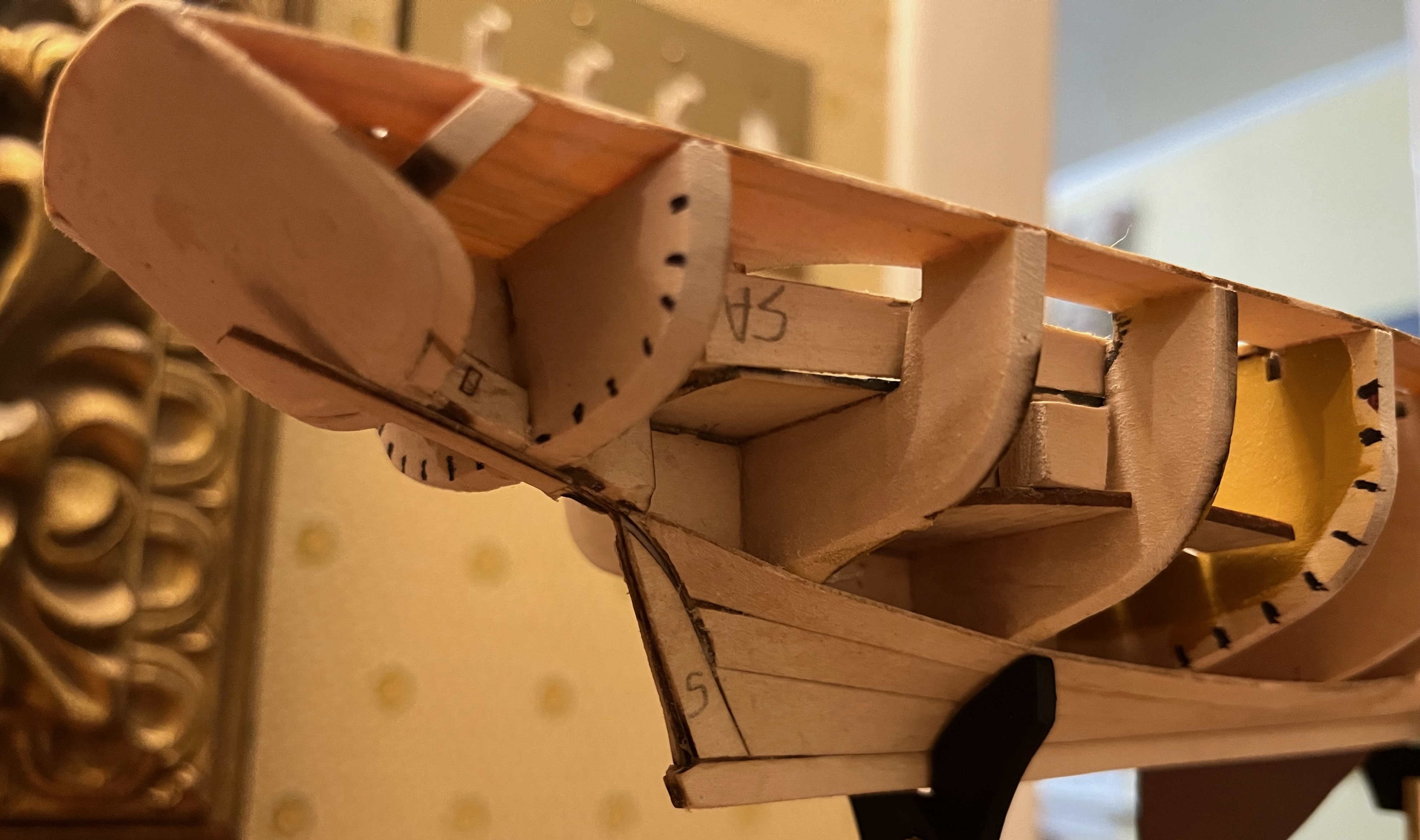
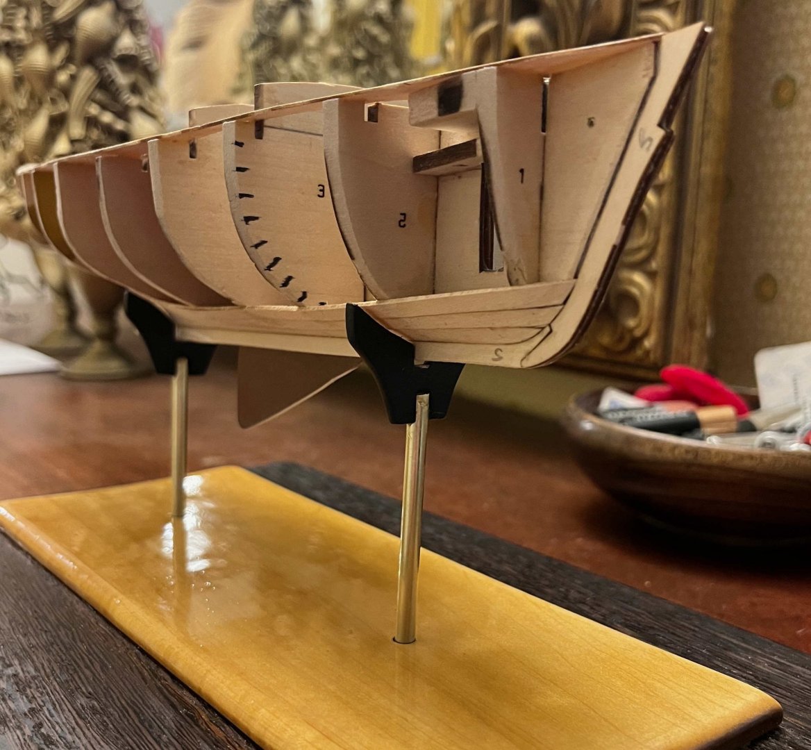
Step 9, Fairing, completed. It proved much easier than I feared -- though until I get to planking, I won't know how well I did at this stage. The upper tips of the bulkheads were easiest: Just sand each one flush with the deck edge. In the end, I only had to add two shims, one of them where I had to re-shape the stern. The bottom of the bulkheads were a little more tricky, though they only needed to reach a feather edge at the end of the outer layers of the central spine structure. Sanding the bulkheads between those limits lacked such easy guidance but the instructions recommendation of a sanding stick-cum-batten (120-grit paper glued to a length of 1/32 basswood) made the midships portion of the hull easy enough. I just sanded until no bulkhead had more than a fine line of char (if any), while the batten worked comfortably across adjacent bulkheads. I did check for port-starboard symmetry, but no issues amidships. The greatest challenge towards the bow was in cutting away the edges of the outer layers of the spine, to form a bearding for the planks. The instructions recommend a knife but I have more control when sanding, so just worked gradually to and fro until happy with the result. I did take extra care to get symmetry between the two sides of Bulkhead 1, as asymmetries there will be especially noticeable when the planking is viewed from ahead. All those issues were more complicated at the stern. One point that the instructions do not mention is that the centreline abaft the sternpost needs to be flat (transversely) and only slightly curved longitudinally, so that it can take a centre plank (in Step 10). That meant a lot of sanding but it is an easy shape to make and then provides a guide to the rest of the fairing in that area. For the hollow sections (mostly Bulkheads 7 & 8), the instructions recommend using sandpaper glued around a dowel. I used an old white-board marker pen (larger diameter) and a pencil (narrow), plus some narrow sanding strips. Getting the basic shape was then no harder than the bow but working for port-starboard symmetry was more demanding. Then came shaping the bearding along the edges of the outer spine pieces, followed by re-shaping everything else. A re-check of my notes then reminded me that previous builds have run into problems where the hollowed, "wineglass" portion of Bulkhead 8 (low down towards the keel) was too wide, making it hard to draw the lower planks to the sternpost. So I did a bit more sanding there. Another problem seems to be bulges in the planking over Bulkhead 7 (worsened by narrowing #8), so I went to some extra effort to get smoothly flowing curves across bulkheads 6 to 9. And then a repeat effort to ensure symmetry. Hopefully, all is done but I won't know until I get to planking, by which time it will be too late for changes! For now, it looks like:


-
The first two show her rigged for 5 squaresails on each mast: course (cro'jick on the mizzen), topsail, t'gans'l, royal and skys'l. The first has the skys'l yards crossed but the sails furled (as are the fore and mizzen royals). The second shows all royals, plus the fore and mizzen t'gans'ls furled, while the skysail yards have been sent down -- as would be expected if stronger winds are forecast to persist for more than several hours. In typical square rigs, any time there is a stay (leading forward) and shrouds, they mark the upper end of a "mast" (even if that is made of the same continuous pole as the mast below and the flagpole above), which is there to carry a yard and sail. The skys'l-mast stays and shrouds are clear in that painting, showing where the skys'l yards would go if they had not been sent down. I think you can be sure that, in terms of terminology of the time, she was a "three-skys'l yarder". Trevor
-
As for many people who follow through the ModelShipways "Apprentice" trio, this smack will be my first experience of a Plank-on-Bulkhead build. While properly stretching our capabilities, as part of the learning experience, David Antscherl has set us a couple of extra challenges. For one thing, the kit has single-layer planking: No rough initial layer, with much sanding and filling before neat, outer planking ones on. Secondly, the smack's hull has some very awkward curves where the run transitions into the counter. Meanwhile, the symmetry of the deck is emphasizing the slight irregularities in my placing of the bulkheads. I figured that I could be less careful that when planking the dory or pram, as any problems could be addressed while fairing. They can be and will be but I will need to shim Bulkheads 5, 8 and especially 10, all on the port side. Not a big deal but one more task. First, however, I extended the laser-burnt tick marks for the strakes, on Bulkheads 3, 6 and 9. A fine-point Sharpie made nice marks but I couldn't get those exactly perpendicular to the edge of each bulkhead, so they will be in the wrong places once those edges have been faired away. I think my marks will still be good enough as guides, which is all they can be anyway. But for anyone following this log in the future: Extend those tick marks before fitting the bulkheads to the spine. That way, you can use a ruler and square to get more accuracy. Starting fairing now ... Trevor
-
You are making good progress! I'll not say that these internal pieces are the hardest of the whole model but they certainly challenged me. Trevor
-
Tidied up the deficiencies in the deck today. The big one was right aft. I whittled a wedge of balsa to take future planking and inserted it where the skeleton of the hull was fell short of the deck: Then I shaped the forward edge of an extra, transverse "plank" for the stern, leaving lots of surplus. Glued in place, that looked a mess: But once sanded and trimmed, with a vertical edge at the extreme stern (as called for by the instructions), it looked quite nice: There is more shaping to do, below the deck's sheer line, but that will come with fairing, planking and the likely filling of hollows here and there. By the time that last image was taken, I had brushed on a first coat of Wipe-on-Poly -- brushed as I wanted to keep it clear of points where glue should go in future, though I didn't succeed as well as I should have. Still, while awaiting a second coat of Poly, I have: The extra piece added across the ends of the planks, at the forward end of the cockpit, is basswood scrap but dipped in golden-oak stain, mostly just for the effect of the visual contrast but also the suggestion of a hardwood edge protecting the exposed corner and the end grain. I doubt that that was normal on Muscongus Bay centreboarders but they certainly could have been built that way if anyone wanted to. Aside from a gentle sanding and a second coat of Poly later this evening, that brings the model to completion of Step 8 of the instructions. Next up: Fairing the hull. Trevor


-
Michael, You asked: Names of species, like names for boat types, get re-used for all sorts of things, often ones quite different to the original meaning. But all of the "true" trouts, salmon and chars are in the family Salmonidae -- which contains 240 species by one count. The chars are in the genus Salvelinus, the Pacific salmons (along with some species called "trout") are in Oncorhynchus, Atlantic salmon (the original and best!) plus a bunch of trout species are in Salmo. But don't get me started on biological names for weird fish species. I'm finally tidying up a list of 250 from deepwater surveys we ran nearly 20 years ago and some of those were seriously weird! And: Been there, too: The kind of weather when you run for shelter after the worst has passed, because you can't while it is blowing. In my case, we had Argentina as the nearest land upwind and Chile somewhere to leeward, with a whole lot of empty ocean between in both directions. But I've worked with commercial fishermen who had seen far worse in far smaller vessels. Then again, I've known people who never came home. Trevor