CDW
-
Posts
7,179 -
Joined
-
Last visited
Content Type
Profiles
Forums
Gallery
Events
Everything posted by CDW
-
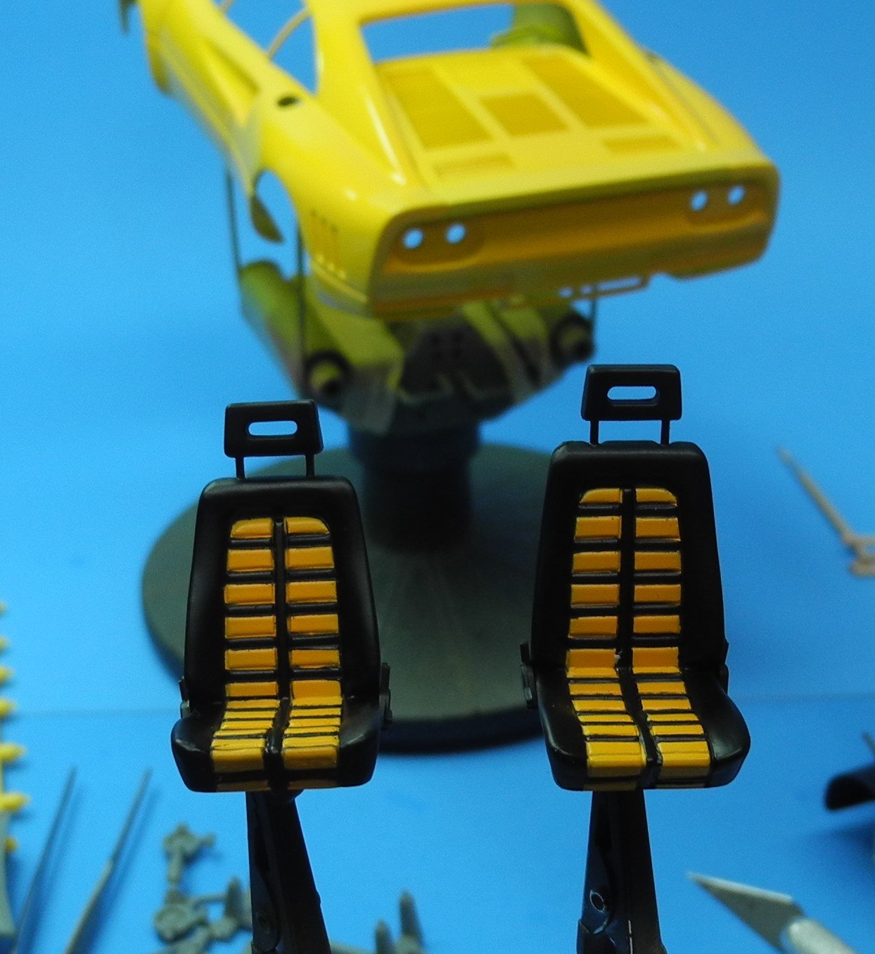
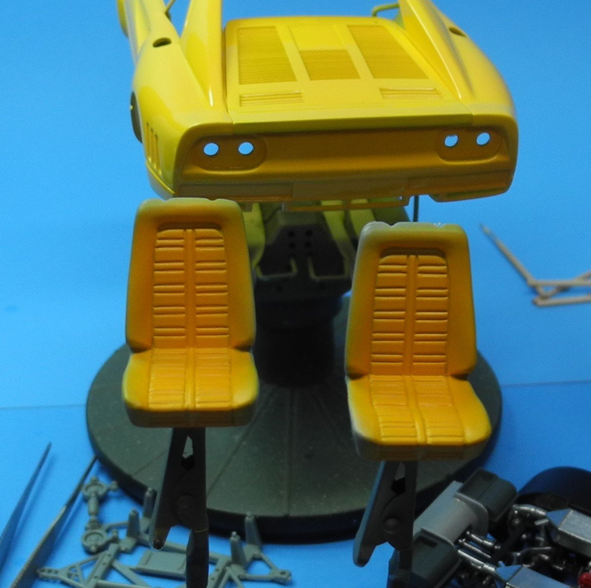
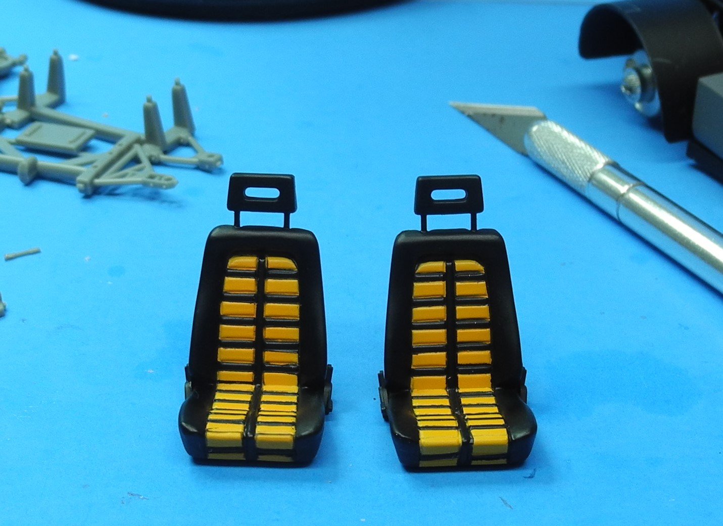
 Here's my interpretation of the seats for the Ferrari 288 GTO Yellow. Are they close to correct? I'm not sure, but they will have to do.
- 95 replies
-
- 13
-

-
I robbed the .50 caliber machine gun from my Walker Bulldog kit to use on another tank project. I ordered this little kit to replace the machine gun. It's a shame to pay 1/3 the cost of the entire kit for one itty bitty machine gun but I did. SSMODEL SS835866 1/35 Model Upgrade US Browning M2 HB 0.50 Machine Gun 1pc | eBay
-
Do you have "Ollie" stores in NY? They bring in cases of random model kits from time to time and sell at a deep discount. Typically, model car kits that normally sell for $30 and up are selling for $12.99, sometimes less. A couple of months ago, I bought a brand new 2 cycle string trimmer/edger for $69.99 at Ollies. That's less than half the cost of Home Depot or Lowes.
-
Thanks Phil
-
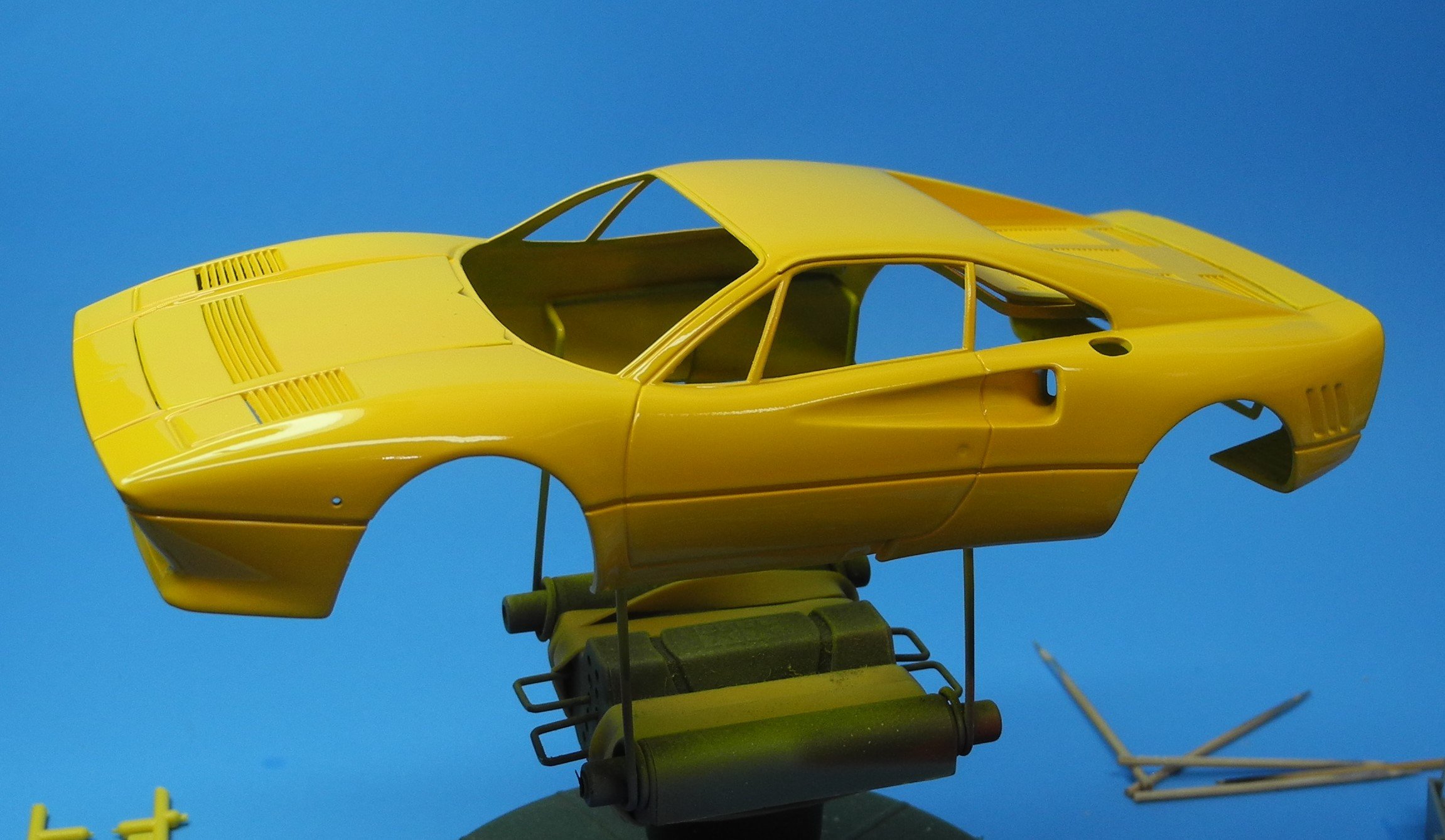
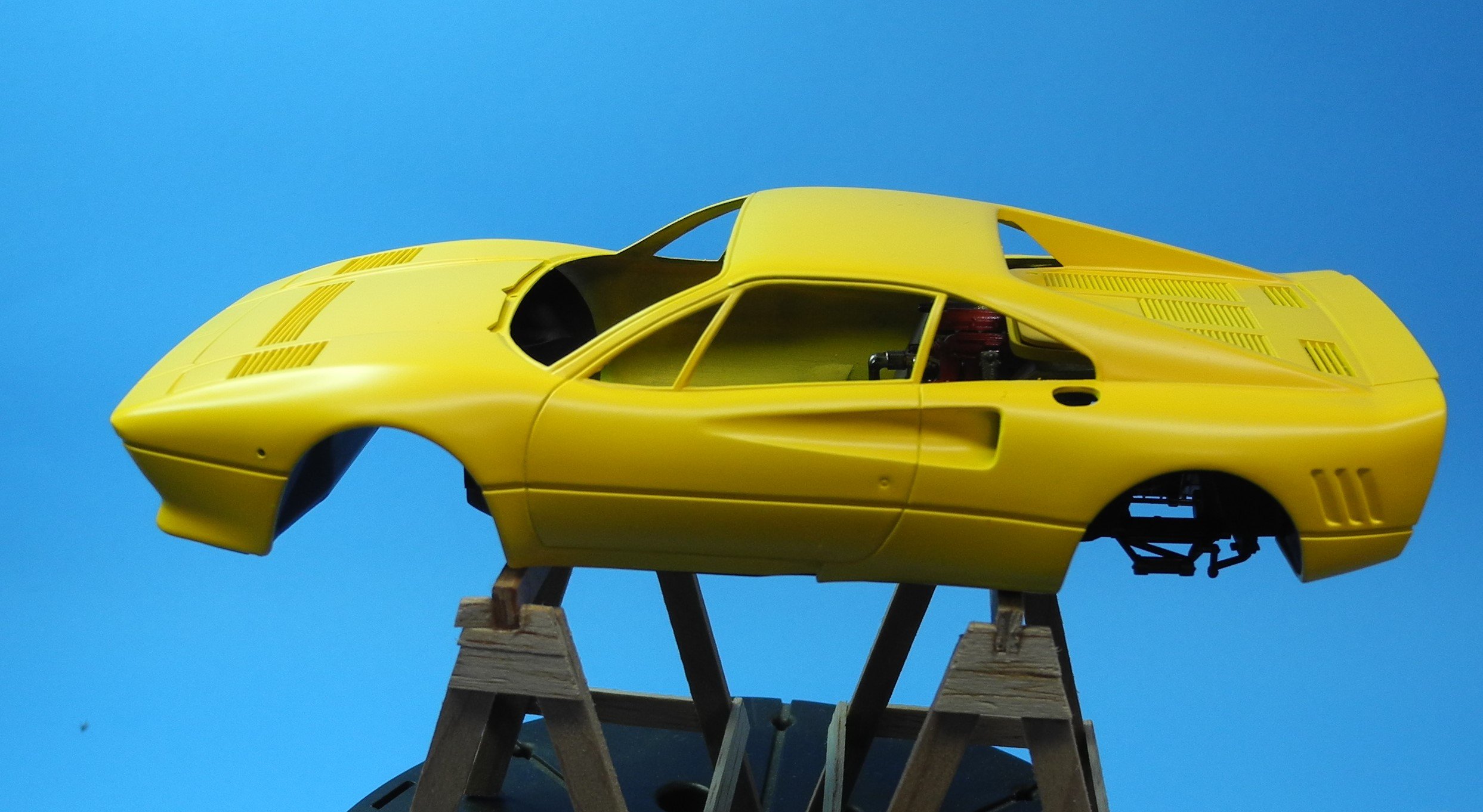
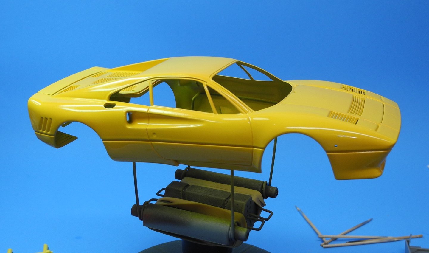
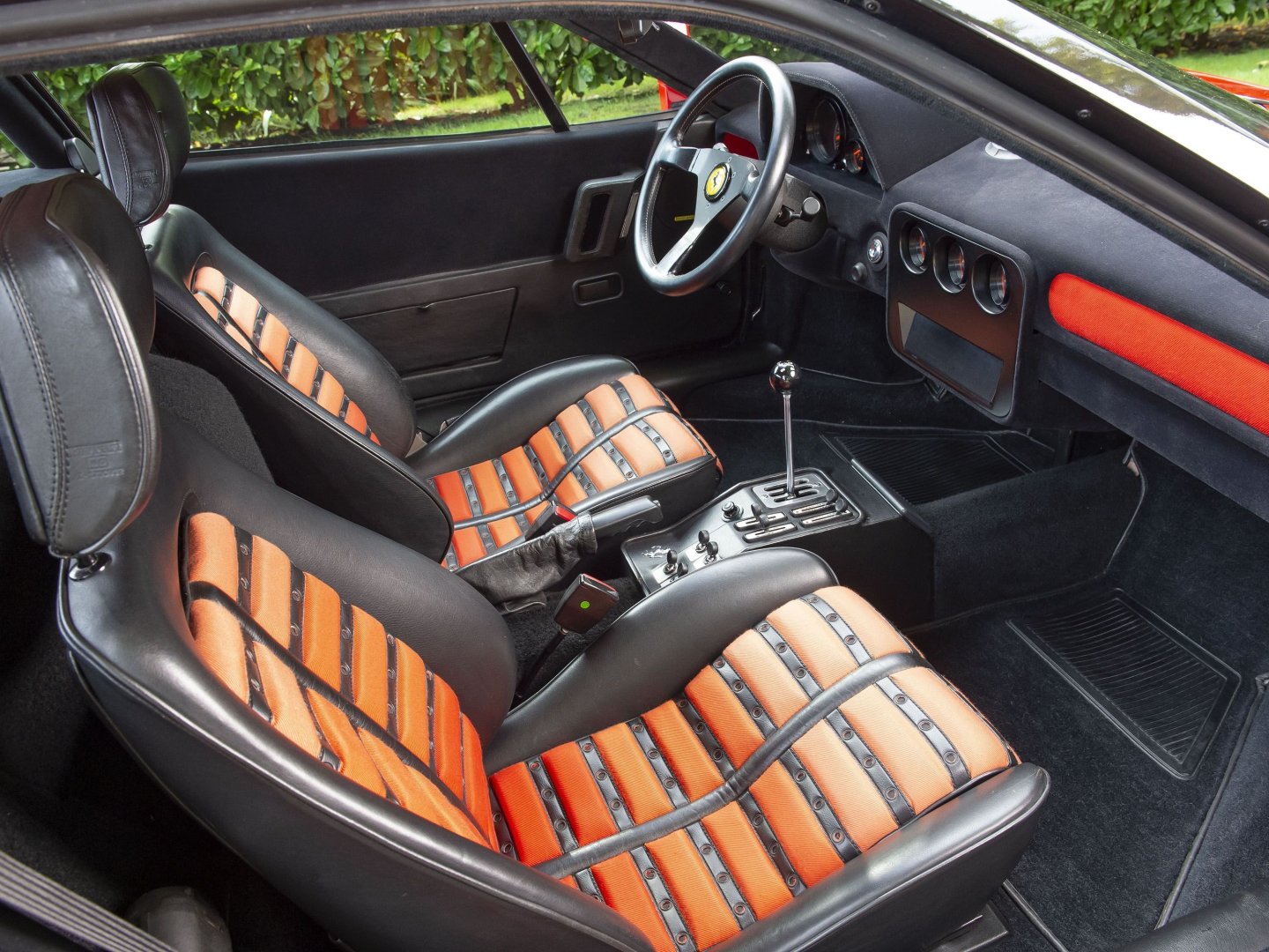
Today, I fashioned those "wings" next to the breather boxes I talked about yesterday. I painted the cover with wings, silver as can be seen in the stock photos. Here's how it looks on the model. Next, I consulted reference photos of the interior on the net. The kit instructions call for the seats to be painted in black with the center panels in red. This seems totally wrong to me with a yellow car. A yellow Ferrari with black and red seats is going to look ridiculous IMO. Unfortunately, I could not find reference photos of the interior in a red car, so I am going to guess they would be black with yellow center panels. My intention is to use liquid mask to cover each little panel in the center, then paint the seats black before removing the masking to show the yellow. Last, I gave the entire body a good wet sanding before laying down another good wet coat of yellow lacquer.


- 95 replies
-
- 17
-
-

-
Yes! Come over tonight and have a piece of cake and a cup of coffee. 🙂
-
Thank you very much. Talent is overrated. Good friends like all of you is priceless.
-
You’re too kind, Alan. Thanks! My cousin who is 95 told me, “getting old is not for the weak” I never had any bad days but now and then have a few sore ones. I’m having too much fun to accept reality at the moment. Or maybe it’s only as real as we believe it is.
-
You guys crack me up and thanks for the kind words. I guess we all are getting closer to “old”. I turned 70 today and don’t need to be reminded I am officially a senior citizen. Heck, even my fishing and hunting licenses are free now. The governor probably knows my eyesight and reflexes aren’t much a threat to wildlife anymore. 😀
-
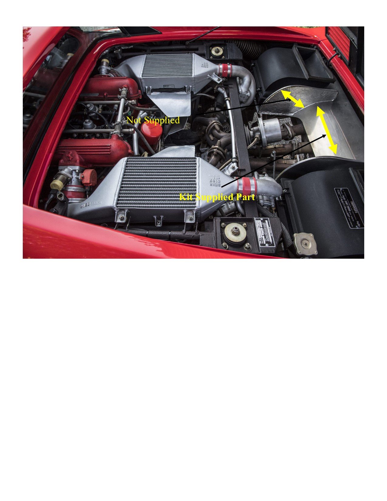
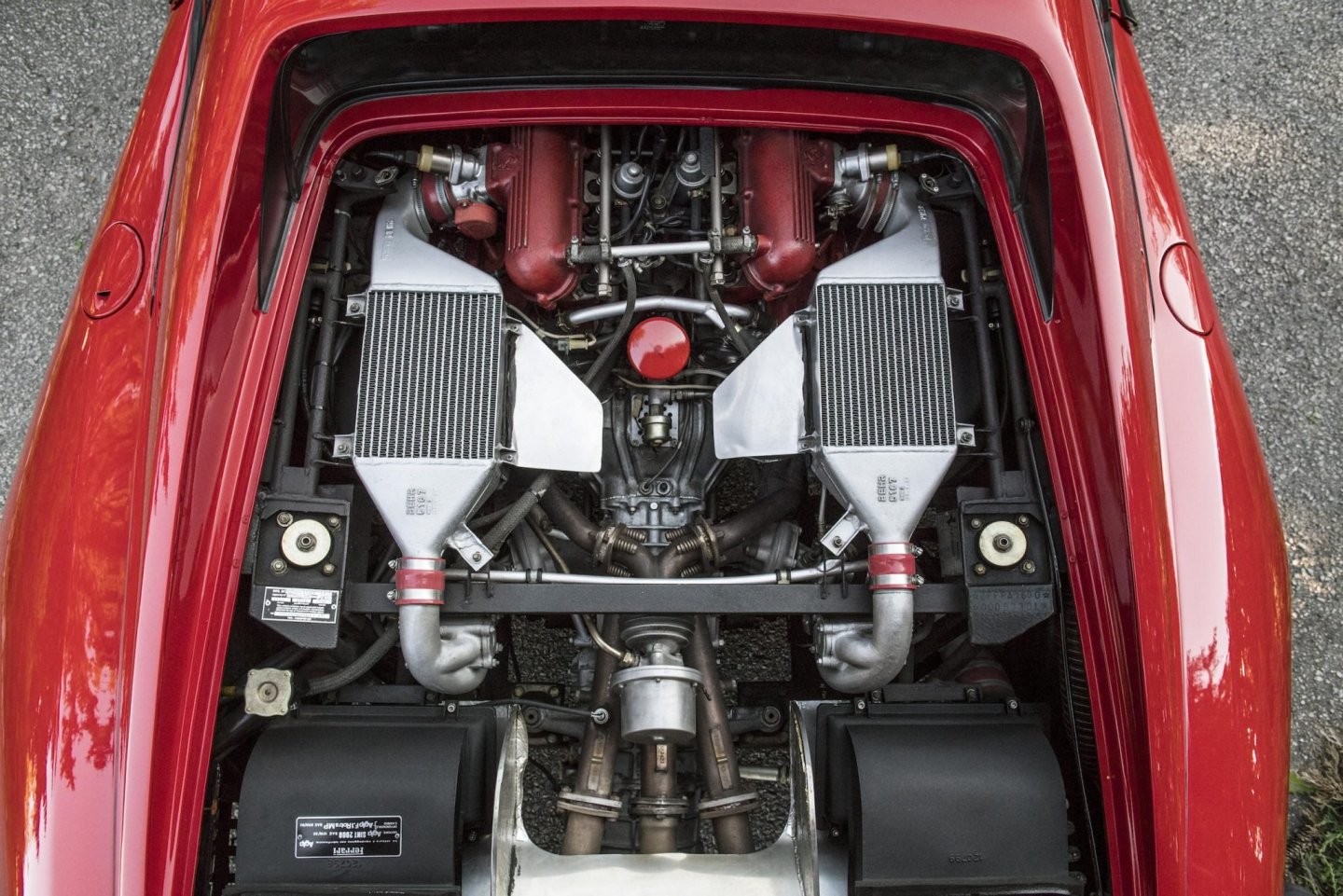
I hope you didn’t really think it was my model. Yes of course it’s a photo of the 1:1 car and annotated to show what details need to be scratch built for the model. It’s a red Ferrari. My model is yellow. You are kidding, right?
-
Outstanding work OC. It’s epic!
-
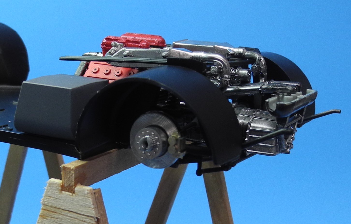
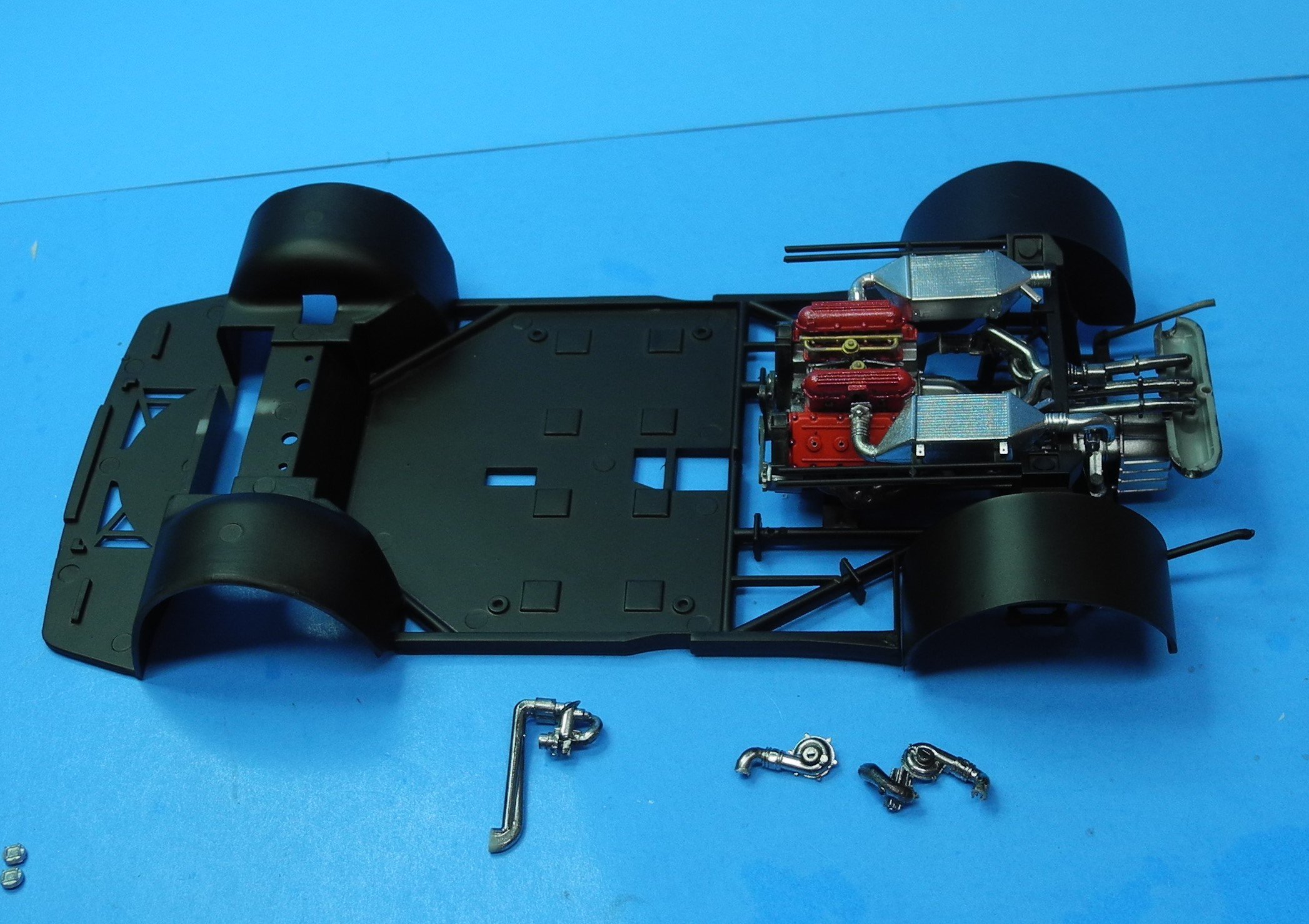
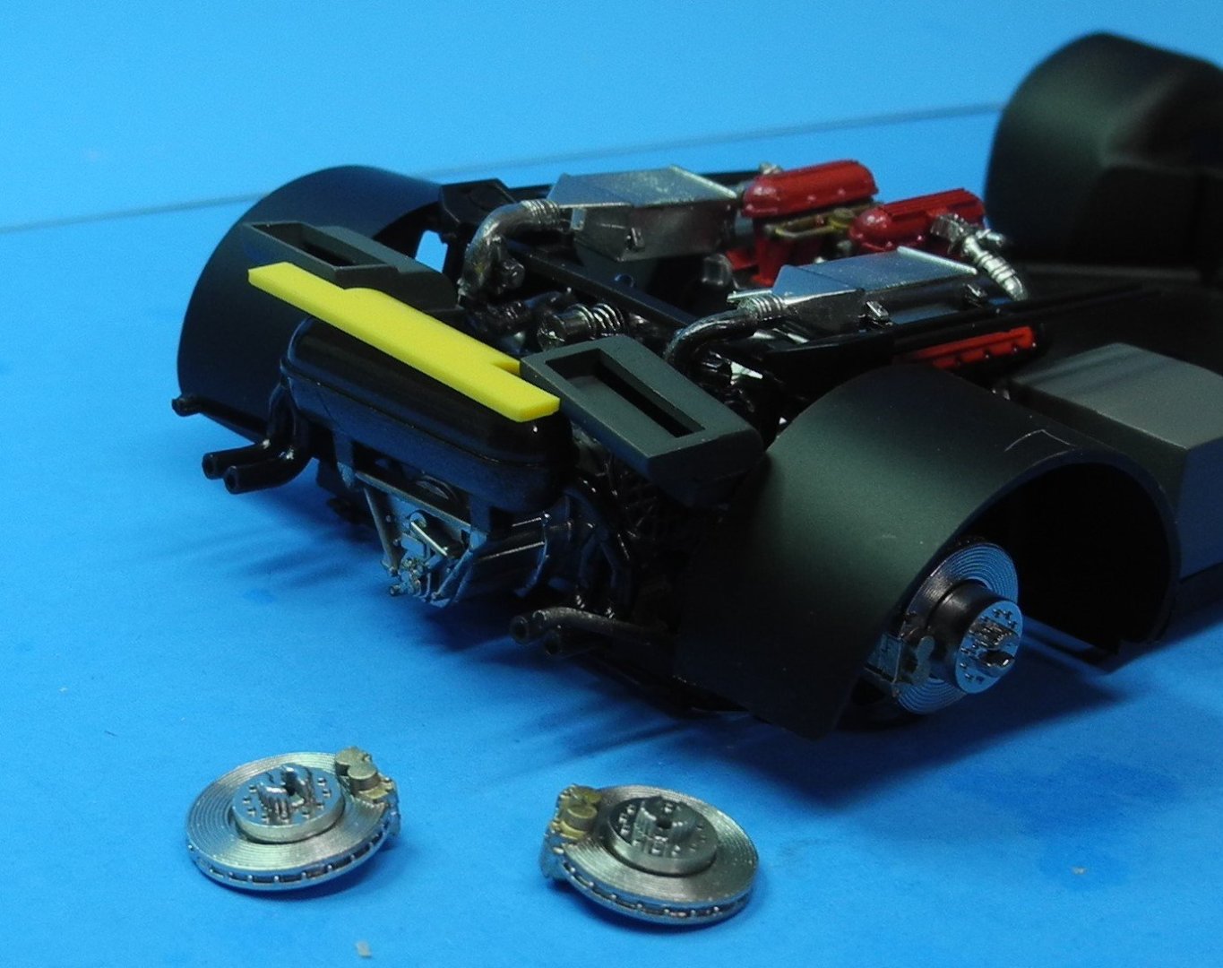
Alright OC...this is so you get your 'picture-fix' before going to bed tonight. The gray breather boxes sit dry-fitted, the yellow piece also dry-fitted needs to be painted aluminum and need the scratch-built vertical wings on each side before being cemented in place. The four exhaust pipes can be seen exiting from the rear awaiting their aluminum exhaust tips. Nighty-nite, sleep tite and talk at 'ya later.
- 95 replies
-
- 14
-
-
-
They are in the mail. You didn't receive yours yet? 😁
-
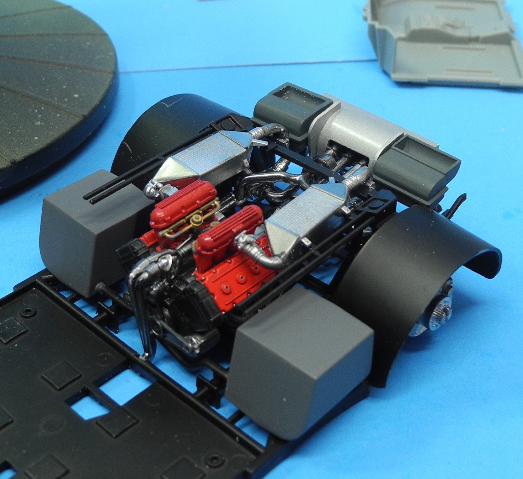
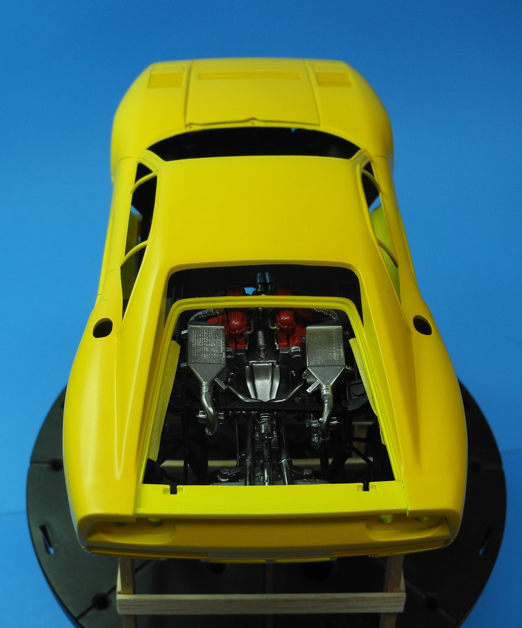
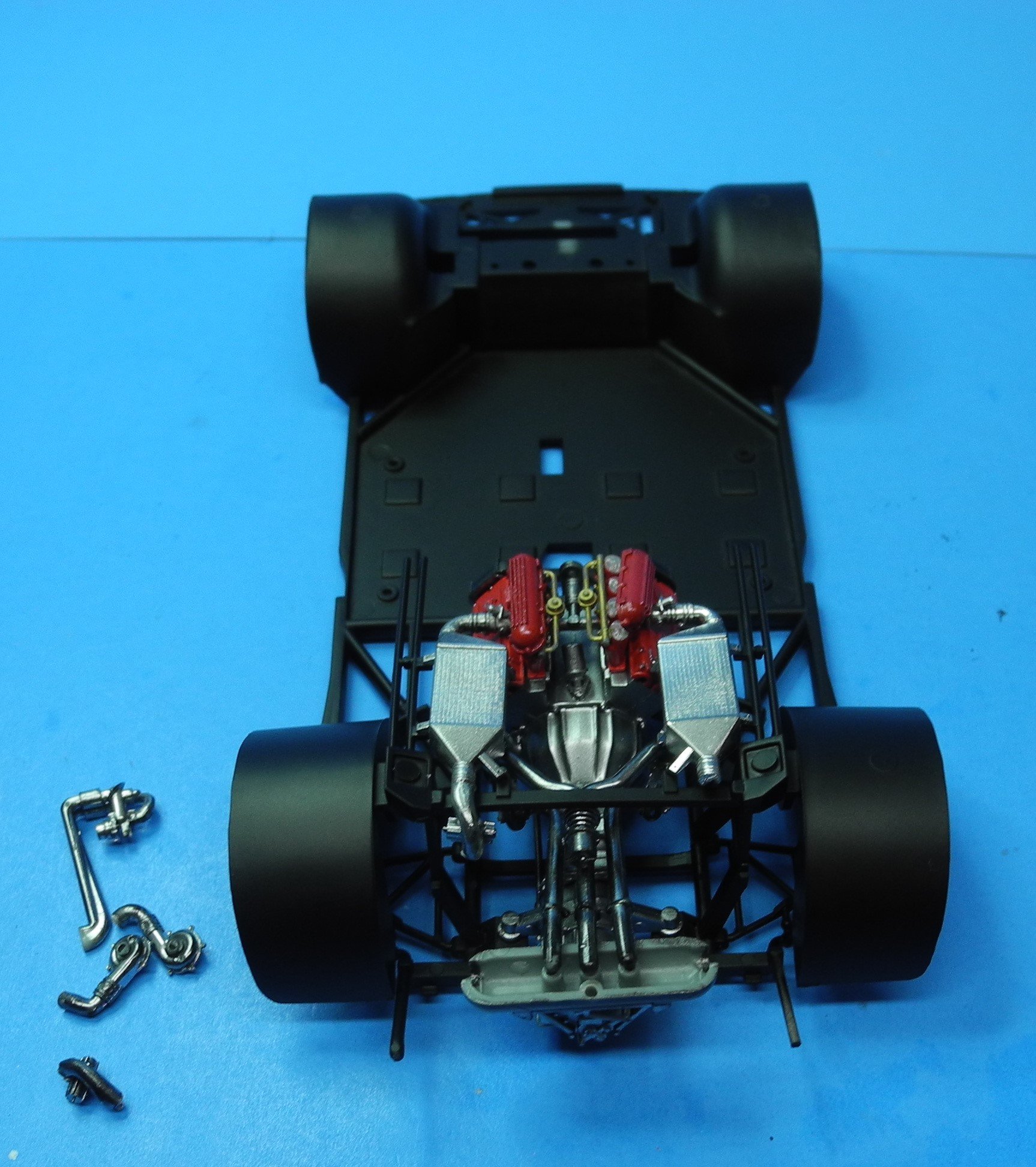
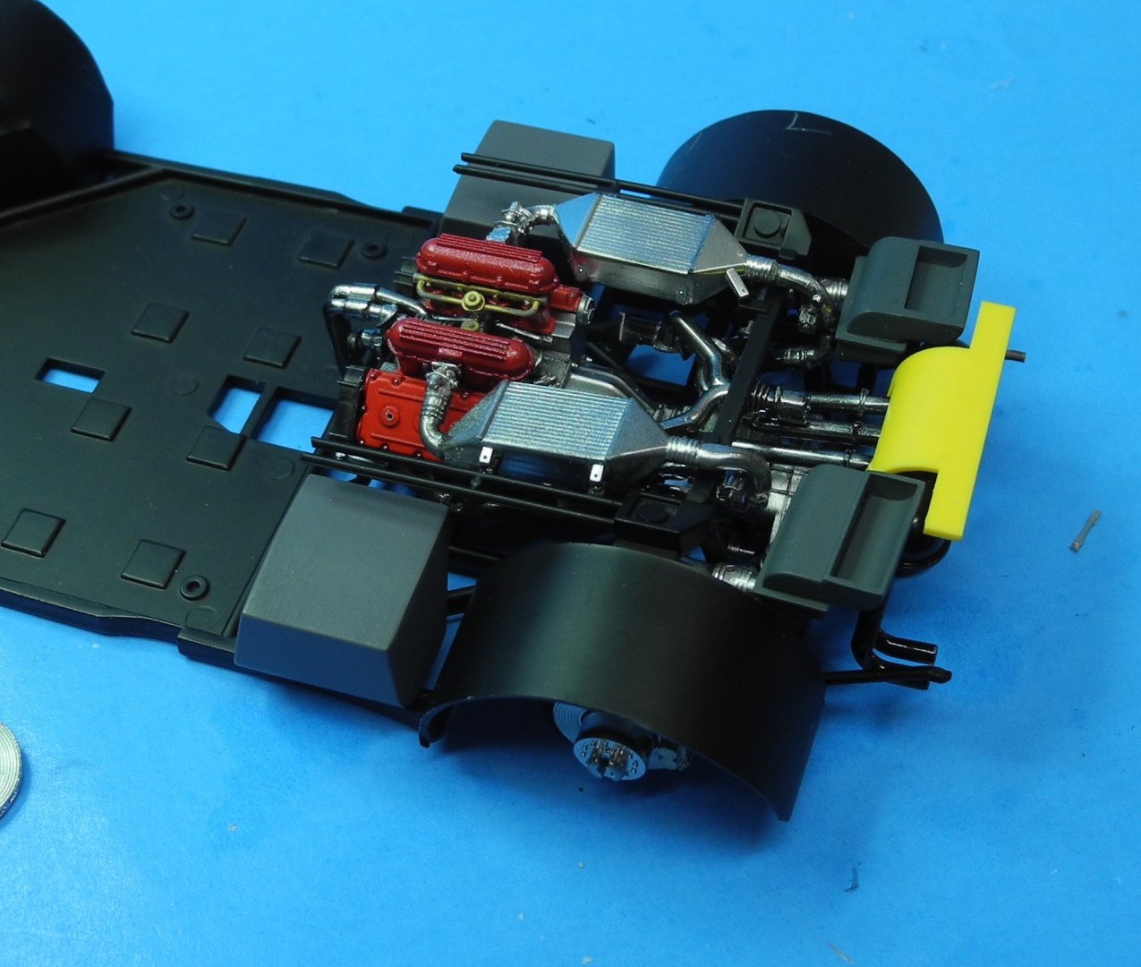
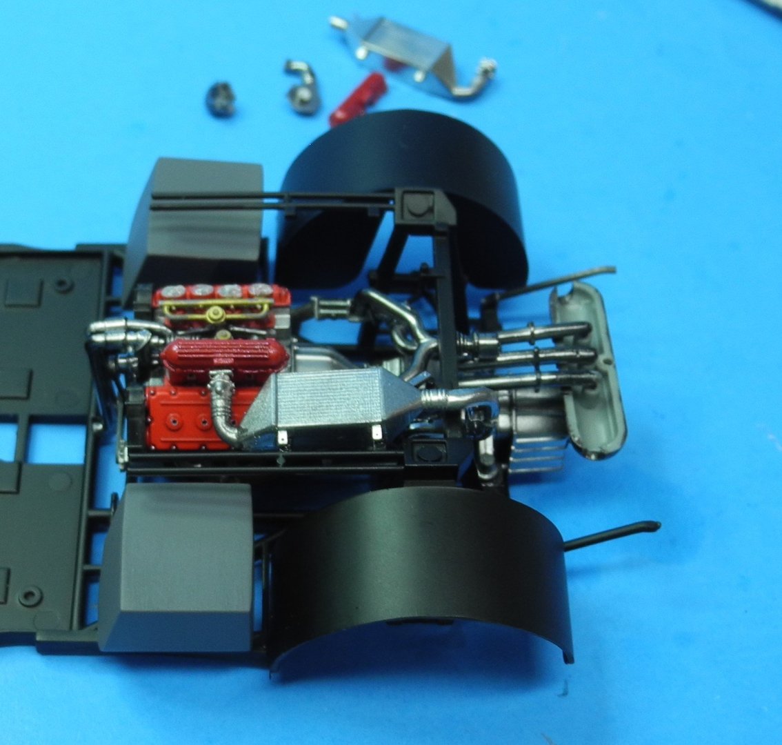
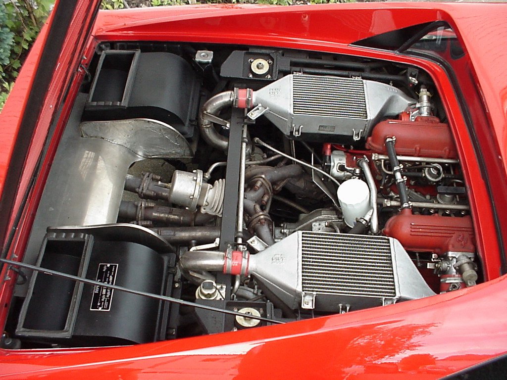
I'm building out the remainder of the engine compartment. The kit provides most of the detail seen in the photograph but not all. The two dark gray boxes at the rear of the compartment are breathers for the turbochargers. These are included. The aluminum plate notated in the photo is also included, but strangely, the two rounded vertical plates are not included and need to be scratch built. Not a big deal to make a couple but just a note for your future interest if you build the model yourself. Some of the smaller details seen in the photo but are not included in the kit, I'll need to decide whether I will or will not take time to add from scratch.

-
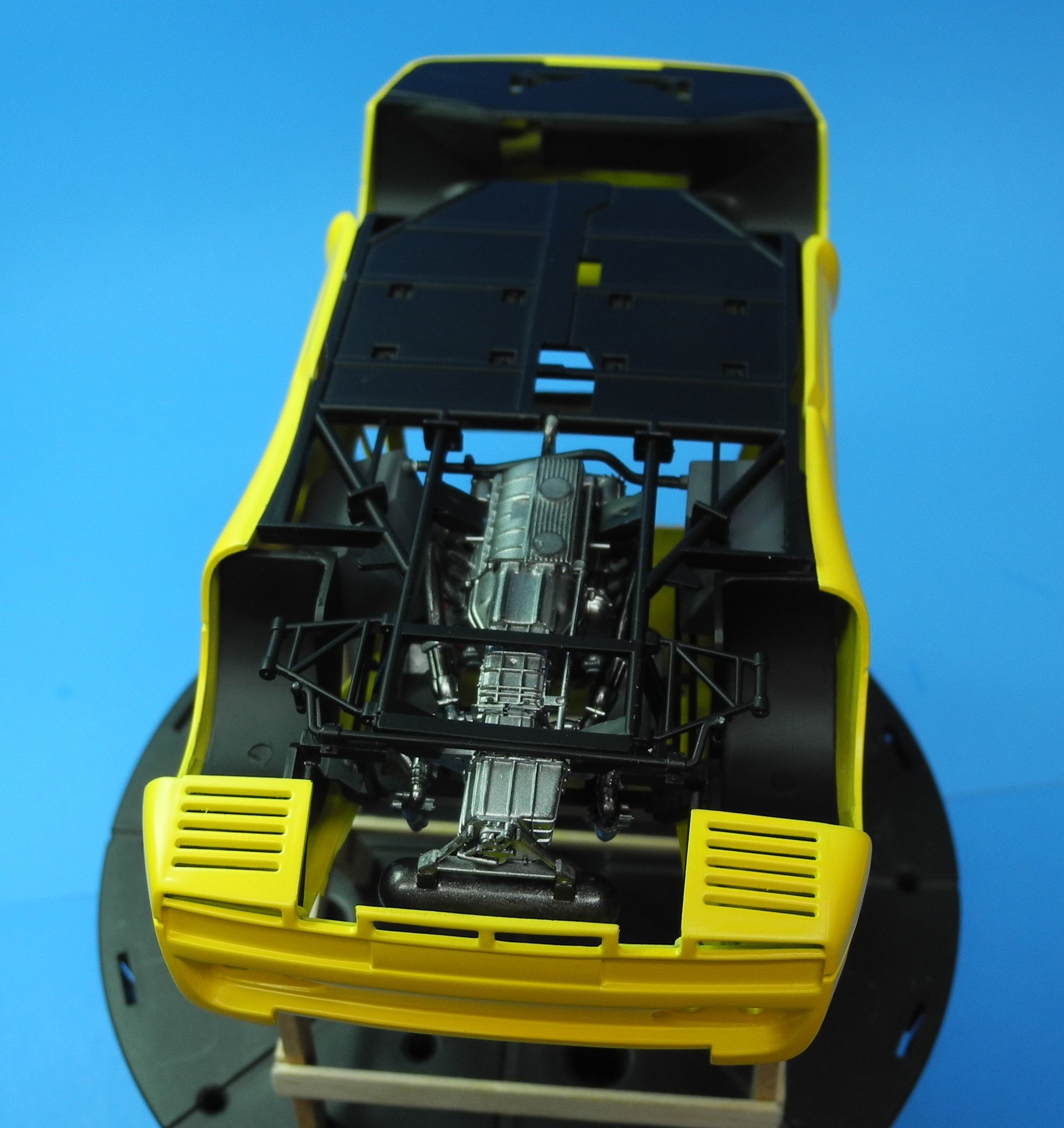
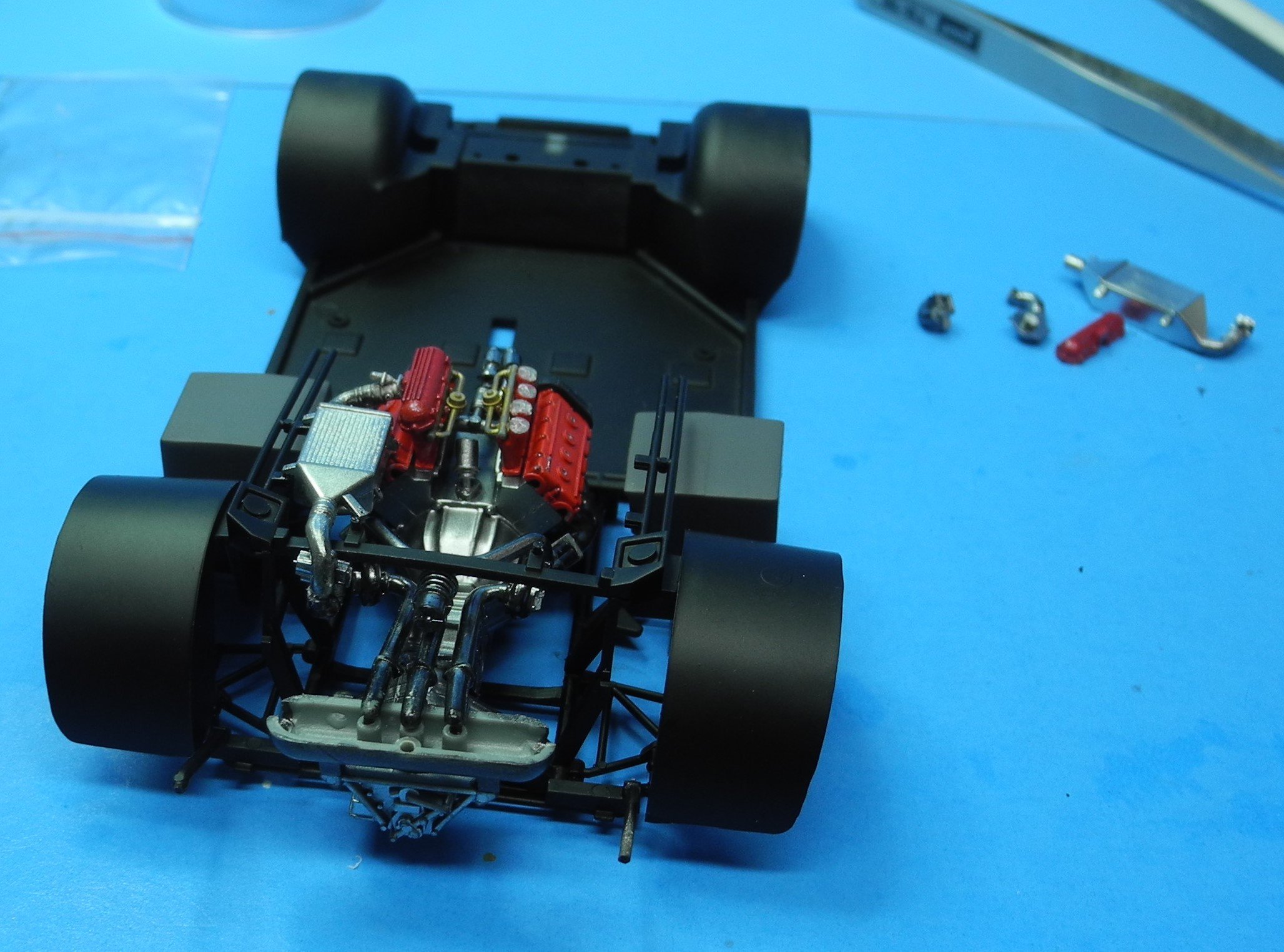
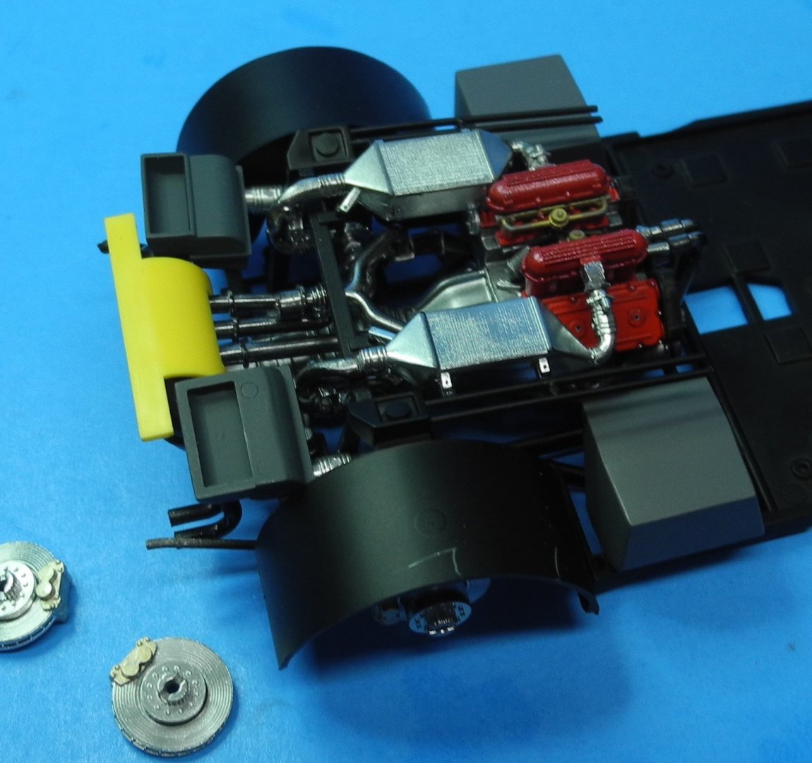
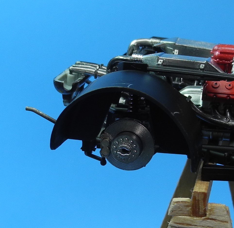
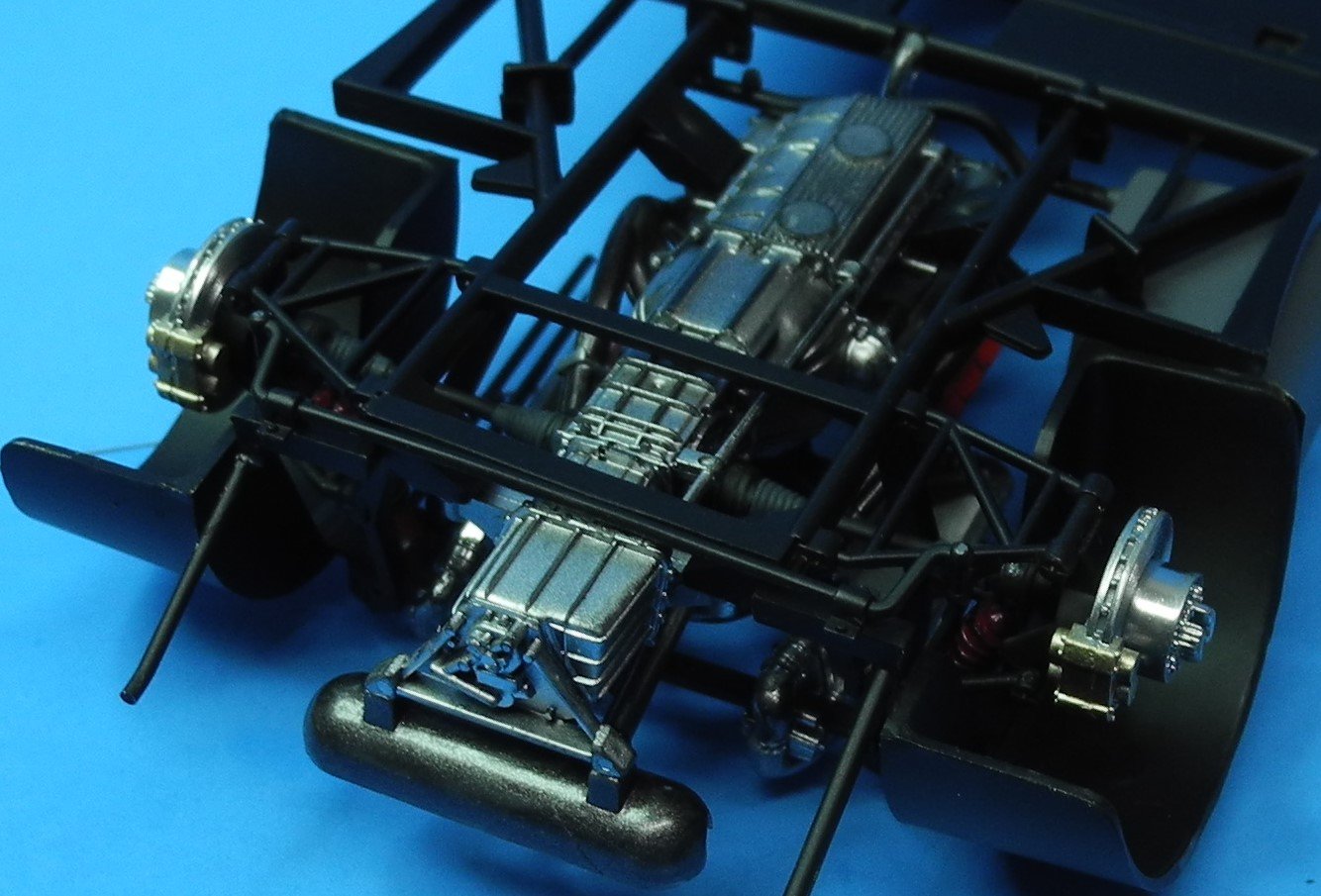
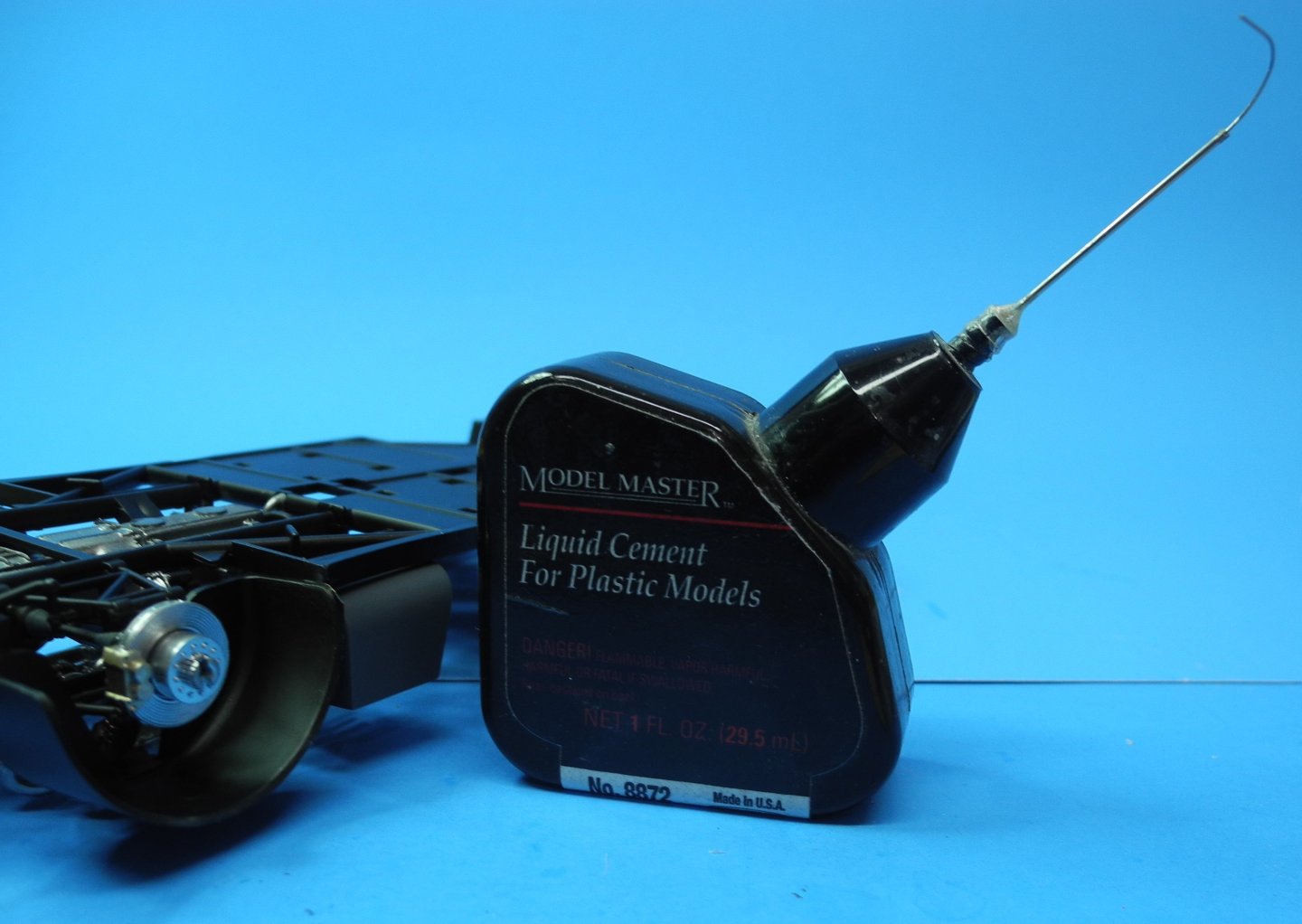
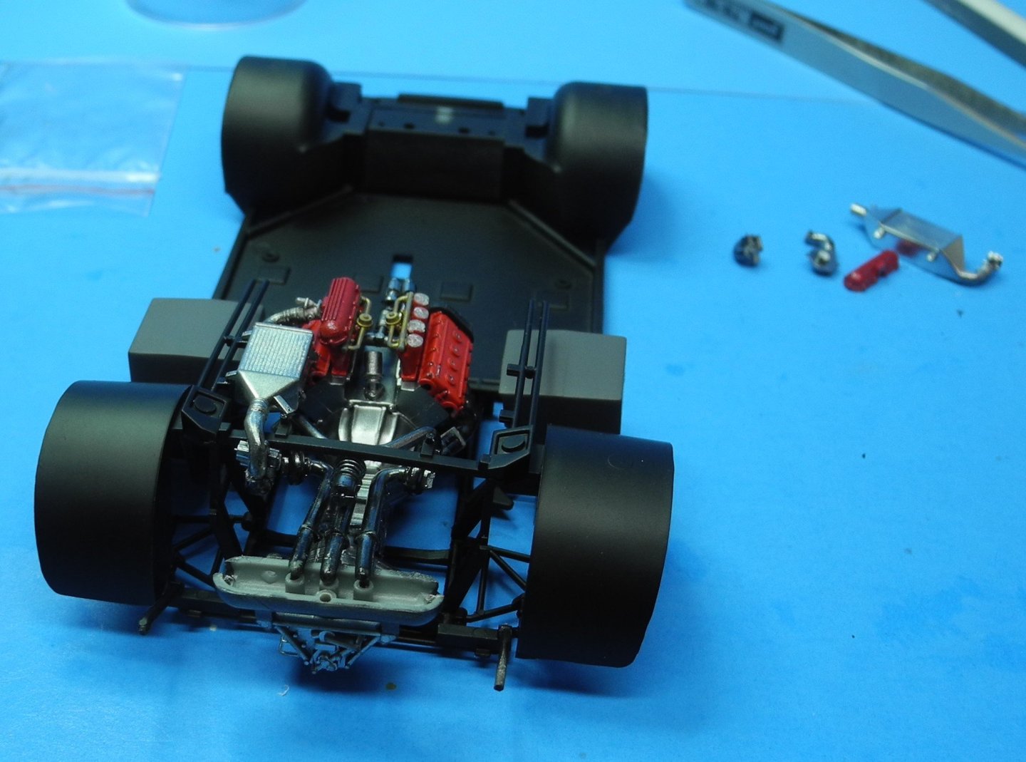
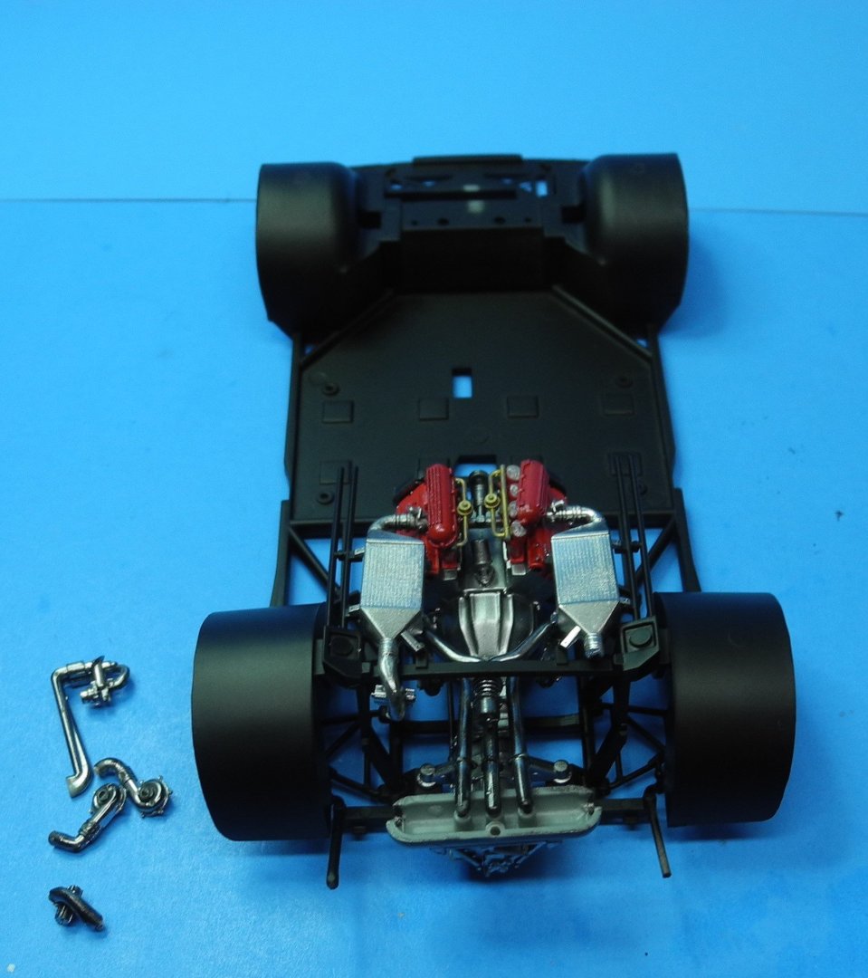
The rear suspension and disk brakes are another area where you will want to take your time, be patient, and work the fit to get it right. It's a little fiddly to get all the parts in place at the same time, but that's what you'll need to do to get a good fit at the glue joints. On assemblies like this, I use the Model Master cement shown in the photos as it has a slower setup time, a precise applicator tube and allows superior control of the amount of cement and location of the same. Unfortunately, this particular product is no longer in production, and I am working on my last bottle of it here. In the future, I will go back to my old standby cement, Faller Expert. It can be found on Amazon if you're interested. As an FYI, I painted the disk rotors and hubs with AK Super Chrome, the calipers with Tamiya titanium gold. The control arms, transaxles in satin black with rubber color boots. The shocks are red with black springs. One of the fuel cells became the first casualty of removing the chassis from the tight fit inside the body. I've made a decision to assemble the remainder of the parts with the chassis outside the body as there is so little space to work the parts into position once the chassis is mounted inside the body. The fuel cell has been repaired. 🙂

- 95 replies
-
- 13
-
-
@gsdpic Something I failed to mention: the instructions show an option to cut open the headlamp covers on the car body as the headlamps on this Ferrari are retractable. However, there are no further instructions to show the parts or part numbers for building out the headlamp buckets once the covers have been cut from the body. This presents no problem for me as I have no intention of building the model with the headlamps in the opened position as I prefer the clean lines of the closed position. There may or may not be parts on the parts trees for building out headlamp buckets, I am not certain. Just a heads-up so you won't get caught unaware.
-
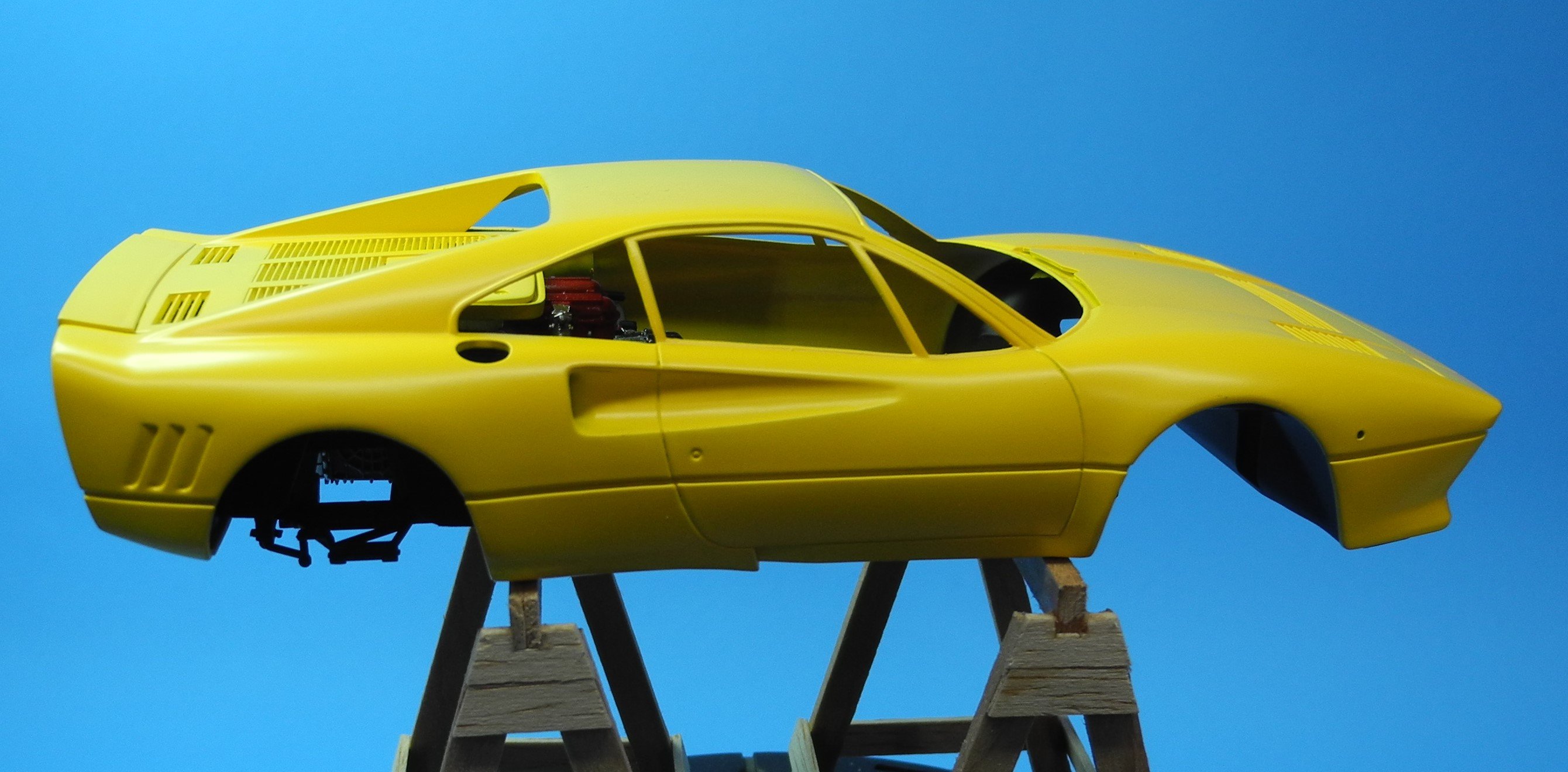
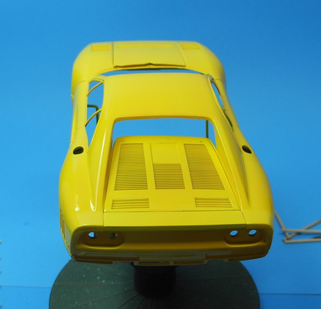
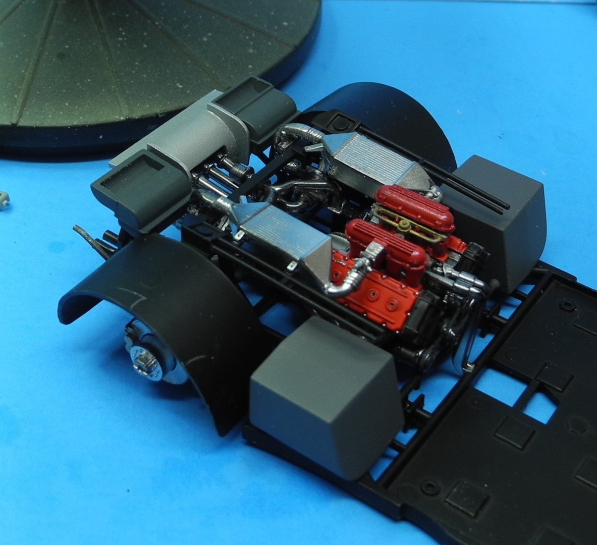
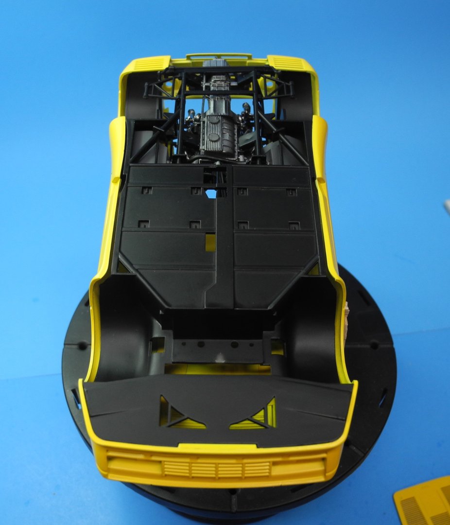
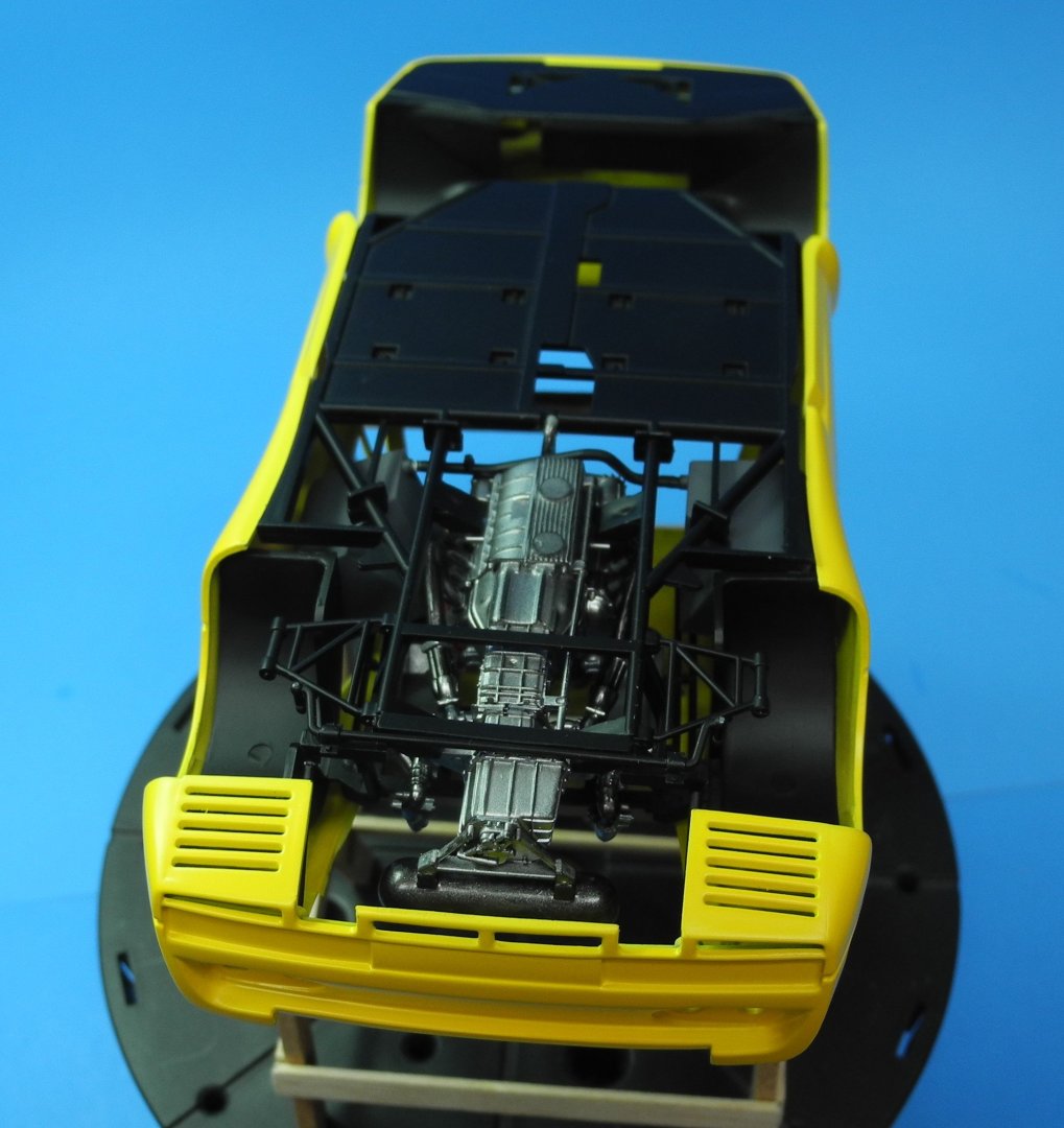
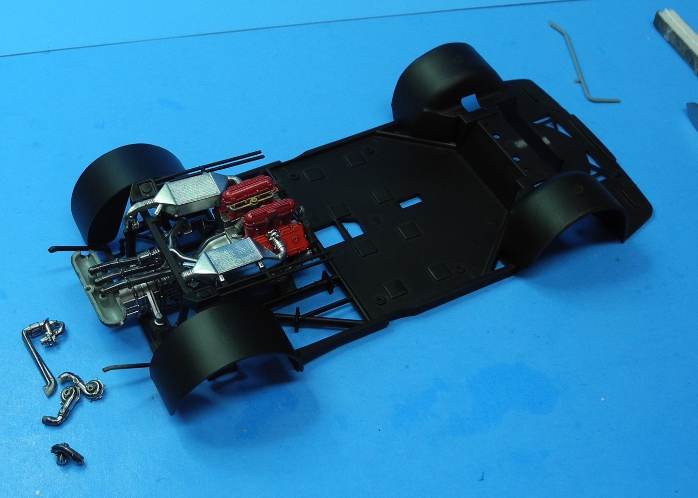
At this stage of the game, it's time to begin test-fitting major components such as the body to chassis fit with the engine and tranny in place. I don't want to get a surprise with fit issues after it's too far along to make adjustments if necessary. While it's a very tight fit, as it should be, it's a precise fit and one I'm happy with at this time. As you will see, it's going to be a very detail-rich model with all the features of the 1:1 car in clear view. That engine in its mid-ship configuration sees a lot of detail get buried, but the turbochargers and air breathers stand proud. That's one of the reasons I was being so careful trying to get those features lined up properly. There's a lot more detail to add and now is the time for me to figure out whether those details should be installed with the chassis in place, or installed with the chassis separate outside the body. The instruction sequence shows the latter, but I don't trust it. With the tight fit being what it is, I'm concerned some of these details to come might interfere with fitting the chassis to the body...it's that tight getting it into position.


- 95 replies
-
- 13
-
-
-
Wow, looks great, Gary. Well worth all the effort you've put into it. On a flying model, those ribs with the cap strips make for a remarkably light, strong, wing.
-
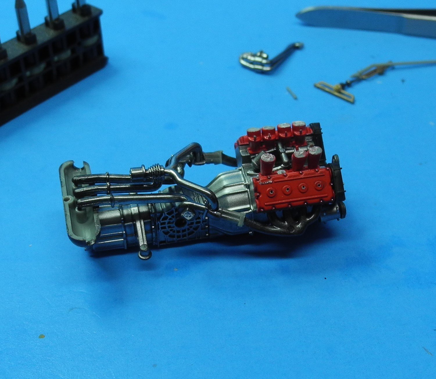
I have good news and bad news. The bad news; this model is one of the most challenging, difficult assemblies to get together I've ever tried to build. It's enough to make a preacher cuss, as my dear old dad used to say when he was working on our old farm equipment. So, hold tight and be patient when you go to build yours, Gary. The good news; I managed to get one side of the turbocharger assembly in place in a half-decent manner. Not perfect mind you, but decent. Without wasting too many words, I'll try to tell you what you need to expect when you get to this phase of construction. If you look closely at the 1:1 photos of the engine bay I posted in an earlier reply, you'll notice that the breathers and injectors are slightly offset when you compare one side with the other. One side sits slightly forward of the set on the other side. The model replicates that offset. However, the model does not make any allowance for this offset when it comes to the turbocharger piping, which has to meet the breathers. I needed to cut off a mm or two from the air breather box shown in my next progress photos to make the piping match up to the opening in the breather. It's clearly an engineering oversight when the model was developed, but it can be corrected with some "field engineering" as I did here. Additionally, at one point I need three hands to apply a dab of accelerator to a super glue joint on the turbocharger piping while I held it in place so that it wrapped around the chassis bracing and down to the other half of the turbocharger extending from the headers. My granddaughter politely and adeptly provided the third hand to apply the accelerator.

- 95 replies
-
- 13
-

-
-
Get a bottle of Mr. Metal Primer. It's clear, self-leveling, dries quickly and can be brushed on photo etch. A bottle of it will seem to last forever. I've used the same bottle for 10 years and it's still half full.
-
After many years messing around with photo etch parts, these two tools from Tamiya are by far the most often ones used from my tool chest to bend photo etch parts: Amazon.com: TAMIYA America, Inc Bending Pliers-Photo Etched Parts, TAM74067 : Arts, Crafts & Sewing Amazon.com: TAMIYA America, Inc Mini Bending Pliers for PE Part, TAM74084 : Arts, Crafts & Sewing The small set being the most frequently used and the large set second most. These particular tools might be found elsewhere for less cost, I just used these links with photos to show exactly the tools spoken of. When you have long photo etch pieces to bend, longer than the largest Tamiya set can handle, then I use a tool similar to the one you own, only it's larger/longer than yours. I've seen other modelers simply use a metal ruler and single edge razor blade to bend photo etch as well. That's the low-cost economy model right there. You are right, the prices on these items have gone up since I bought them last. 🙂 PS: If you can find a 12" x 12" or similar size piece of black acrylic sheet, it's perfectly flat and a huge help when cutting or bending photo etch. The black background makes it much easier to see what you're doing, particularly when cutting photo etch from the frets.
-
King Tiger Diorama by chadwijm6 - FINISHED - Airfix - 1/35
CDW replied to chadwijm6's topic in Non-ship/categorised builds
Don’t know if you are interest ex d, but there are some nice 1/16 scale figures on sale at Andy’s Hobby Headquarters on line. I was just looking at them on his sale page today. These are new ones that have recently been released. -
After looking over the photos of the 1:1 Ferrari engine bay, I will not go through the effort to install ignition wiring. All that detail will be buried and hidden from view, so in my opinion, it would be a long climb for a short slide. Just one more thing I realized after studying photos of the 1:1 engine; the instructions show parts E6 and E5 installed in the wrong locations. They need to be flipped. See the 1:1 photo and then look at the intsructions. You'll see what I'm talking about. In a way, it really won't matter too much if you get it wrong as it will be buried from view in either event. I only discovered the error as I was looking at 1:1 photos to create ignition wiring.
- 95 replies
-
- 10
-
-
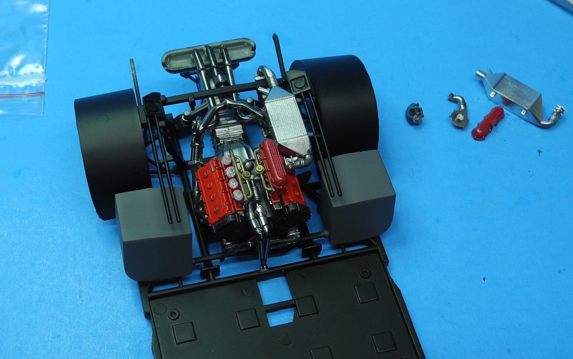
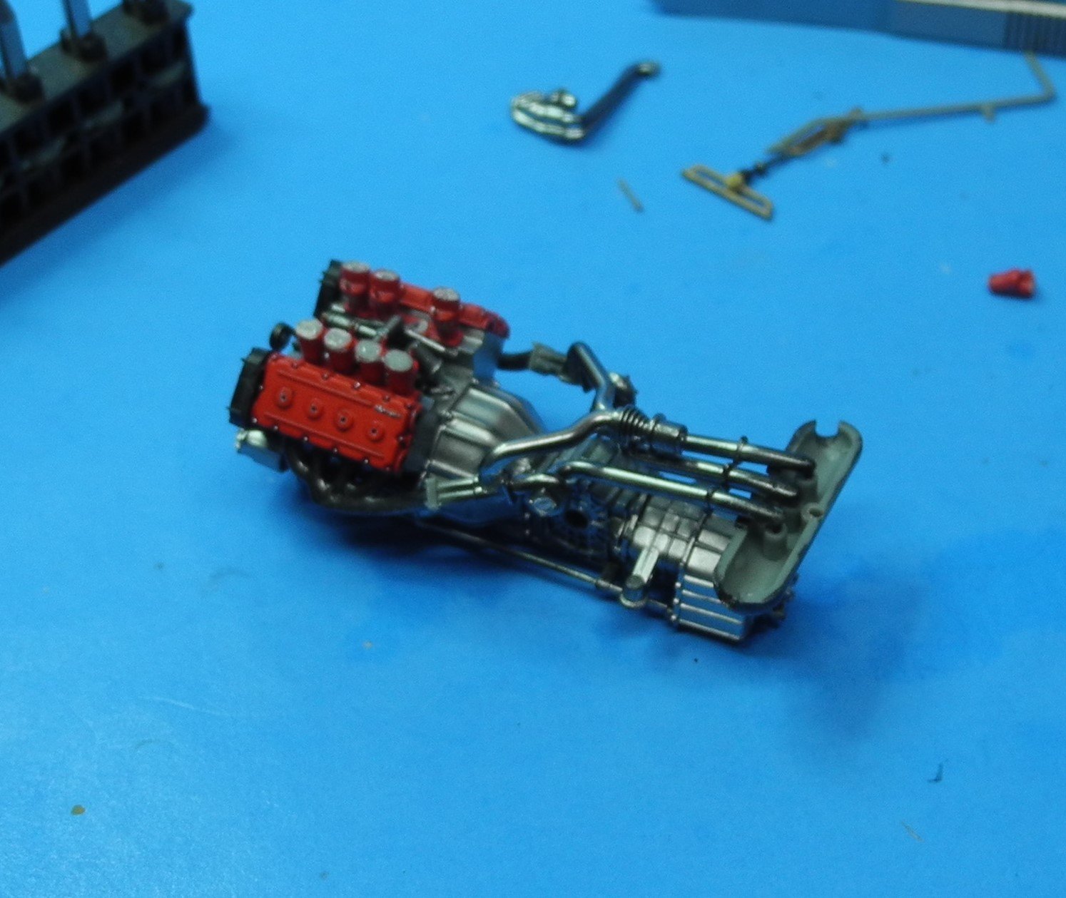
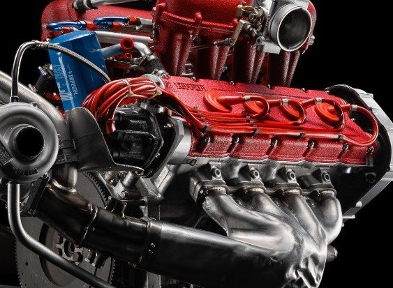
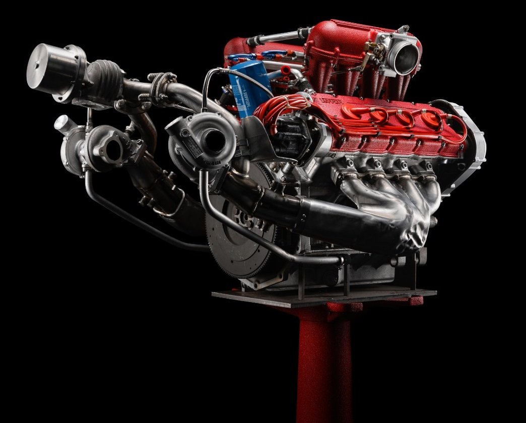
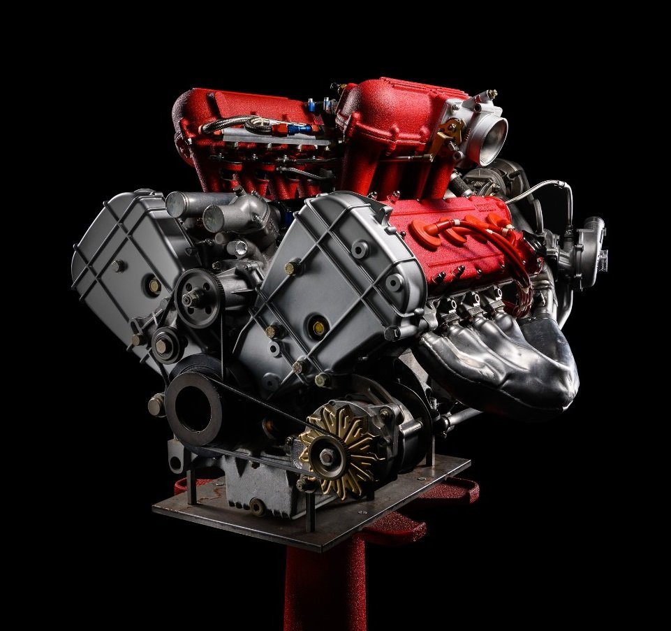
Mea Culpa: I erred when I followed the instructions sequentially rather than looking further ahead in the instructions first, then looking at photo references of the 1:1 car. The kit offers the option of displaying the engine separately on an engine stand. If I had intended to do that, following sequentially would not have been a problem, but that's not what I wanted. I wanted to display my engine inside the chassis, inside the car. Again, looking at photos of the 1:1 car is essential to getting this complicated turbocharger assembly right. The instructions do a poor job of pointing this out, but it may be a language barrier problem. I can't read Japanese so I have no idea what the instructions may or may not say about sequence, but the photos in the instructions certainly don't point it all out clearly. Here are 1:1 photos of how the complete engine and turbocharger assemblies would look. Here are photos of the 1:1 car/chassis with the engine and turbochargers inside the chassis/car. I found that I first needed to glue the headers to the parts labeled E36 and E37 in the instructions. Next I attached parts E53 and E57 to the turbochargers and then attached those to the collector box D7. Last, attach parts E29 and D36 to the turbocharger and header assemblies as seen here. The chassis and components shown here are assembled and painted before installing the engine assembly. The remainder of the turbocharger parts, the air breather boxes as well as the injector covers are only installed after the engine is in place inside the chassis. My engine and breather boxes are dry-fitted here in the chassis for purpose of explanations of the sequence to follow. Do not assemble all the turbocharger parts as one assembly. The only way that could possibly work out okay is if you intend to display the engine on a stand rather than inside the car.


- 95 replies
-
- 11
-
-