Walter Biles
-
Posts
356 -
Joined
-
Last visited
Content Type
Profiles
Forums
Gallery
Events
Everything posted by Walter Biles
-
 I am now up to 18 of 31 frames done. I had a few days when my CAD program wouldn't work. It got some sort of error in the program which I finally had to remove the program and then re-install. Now it is back up and the frames are getting better all the time, as I find things I did wrong. I had been finding frames that I had left out some things that needed to be there for the frame to come out right. They are getting better as I go.
 -
I had to do a lot of re-working the frames, to try to get the outside planking and the inside forward side of the frames delineated and get the basics of the keel marked in the same for all. I now have 16 frames done, and am into the middle frames where the fore and aft are pretty much the same. Now I can settle down to get the rest of the frames drawn out. Here are a few sample drawings of the first two another two.
-
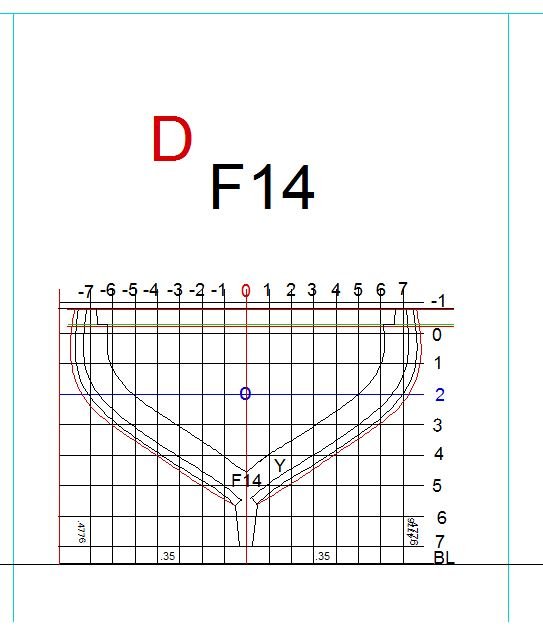
Here is the example of the F14 FRAME in it's final(I hope) format. The RED lines are on the AFT side of each frame. I have only included those lines to show the outerline differences so far. I believe the aft sides will be taken off to a separate layer once I get these done. Then I can turn off that side when needed for clarity. Trying to put too much on one layer can make things confusing. I have found a number of omissions to my previous frames in the process of doing this tutorial. I am going to have to go back through them and redo them to include the planking thickness adjustments and ensure that they will all have the rabbet and bearding and the deck levels all right. I am astounded that EdT can keep track of making everything so accurate. I have sure found that I haven't.
-
I now have 14 of my 31 frames drawn to scale. I am not saying that this is the only way to do these frames, because there are many ways to achieve the desired effect. I just want to provide others with whatever help they may derive from my work efforts. My hope is that once I have all my parts drawn in to a specific scale, with CAD, it is easy to print these plans and/or frames out to any scale with a minimum of effort for any particular scale you want to make a ship. Once I get all my frames done, then I will be using these drawings to make the 7 part built up frames for a model of as yet undetermined scale for Radio Control.
-
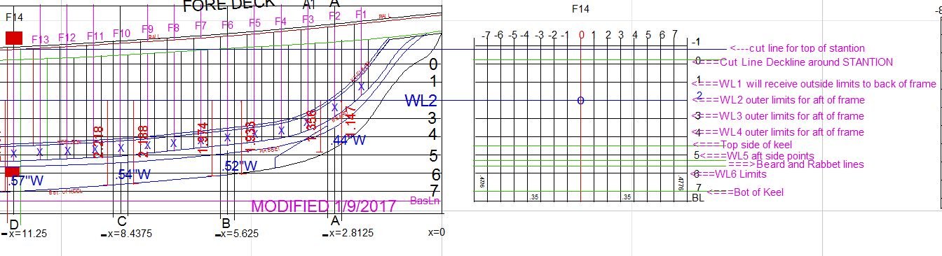
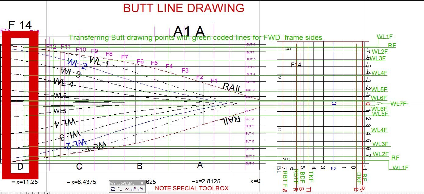
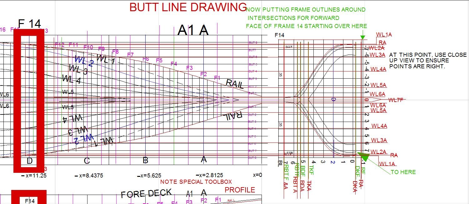
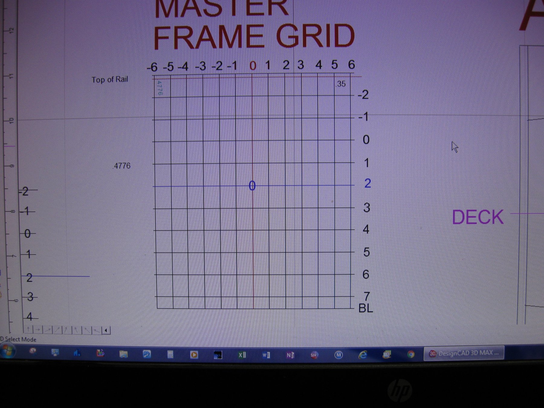
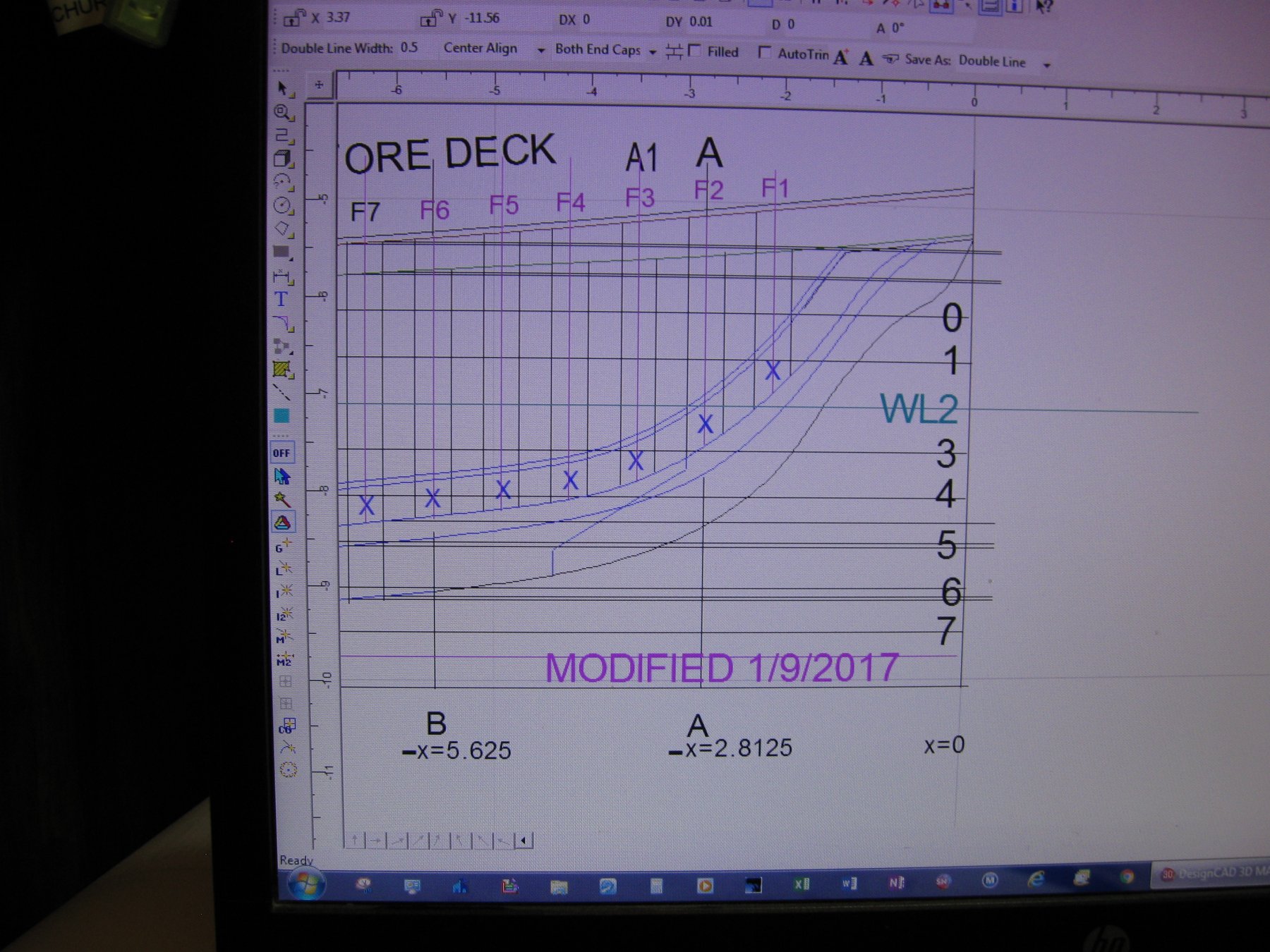
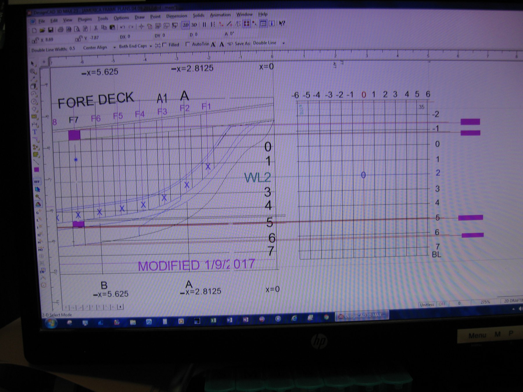
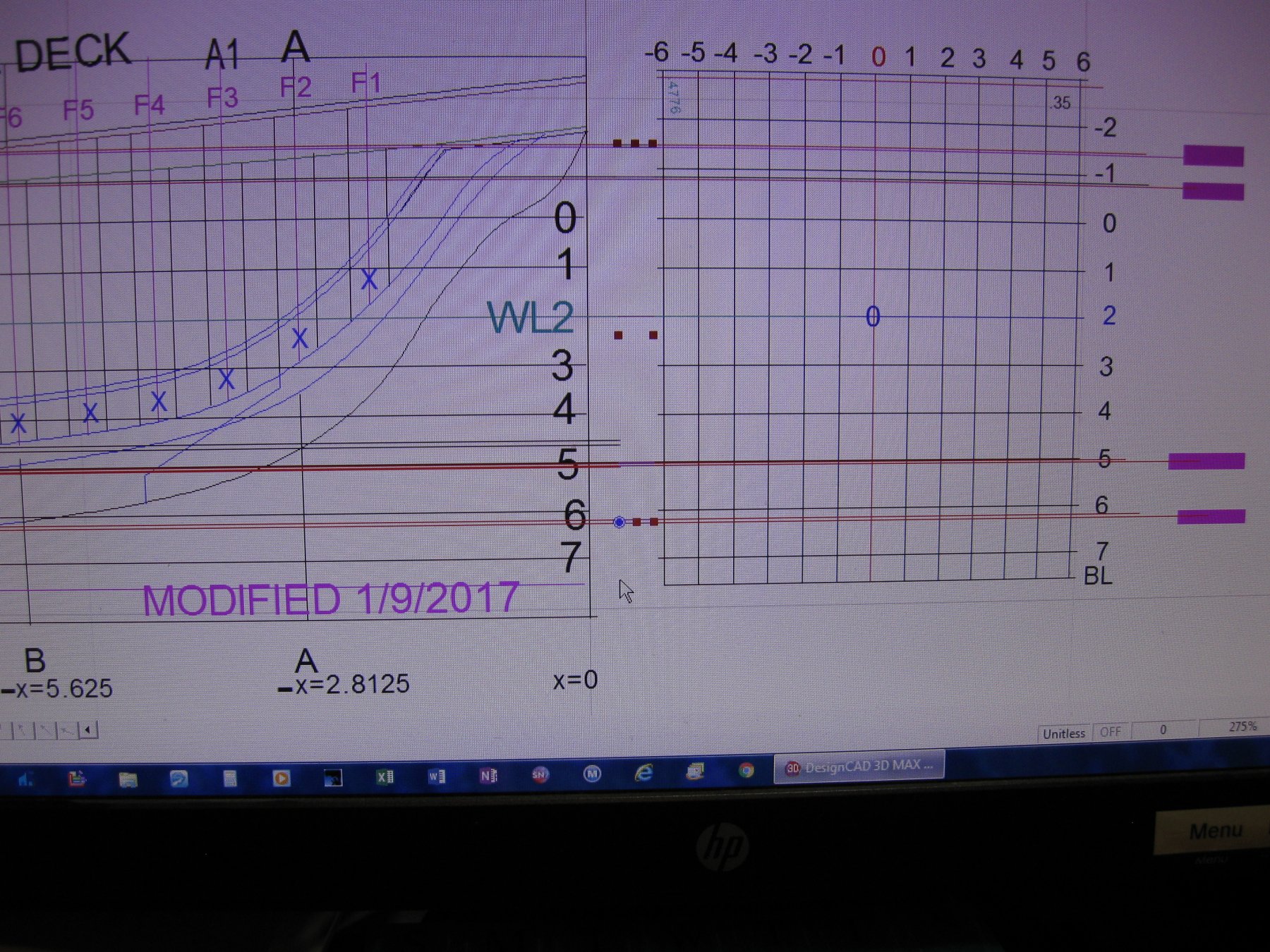
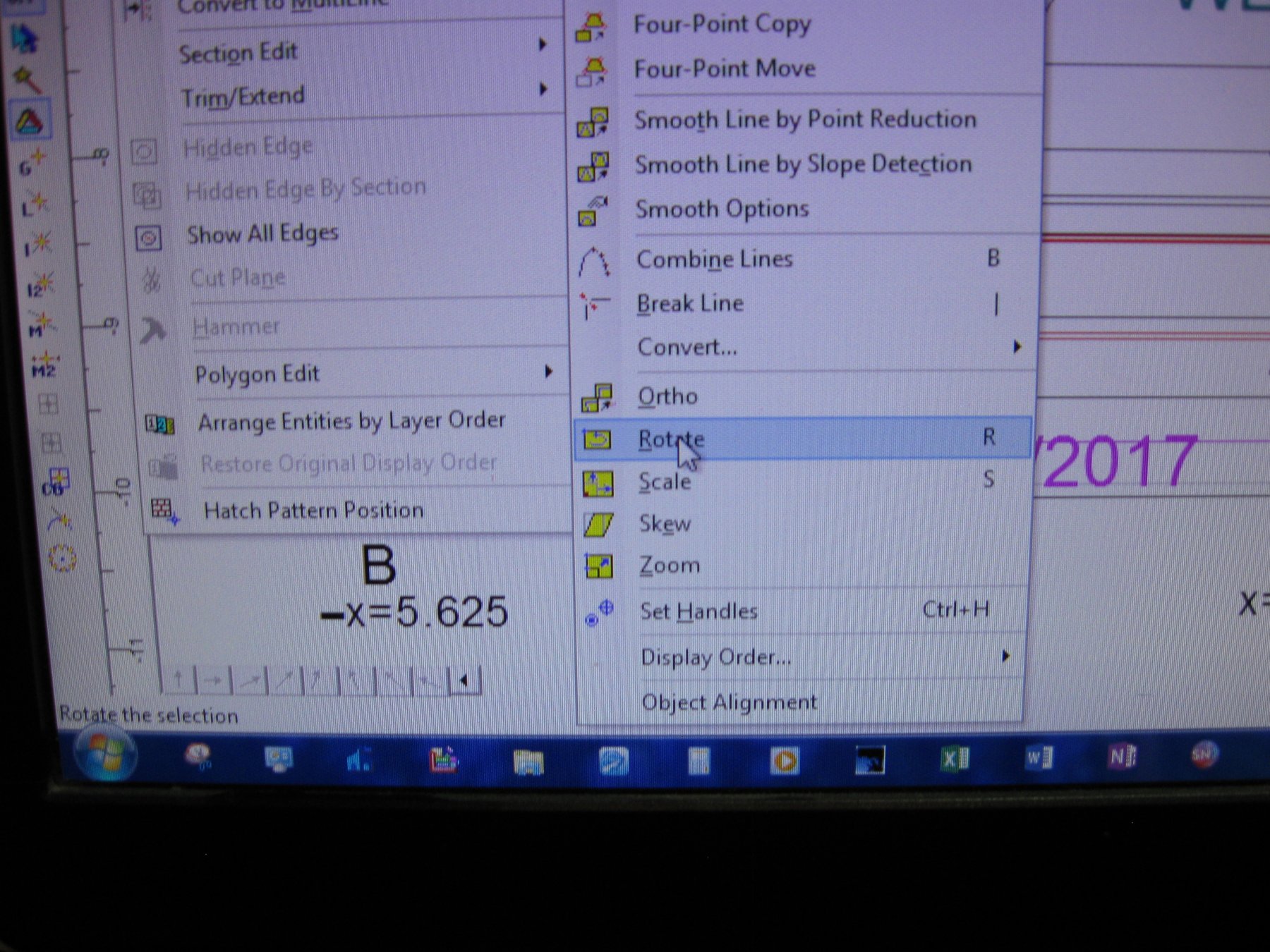
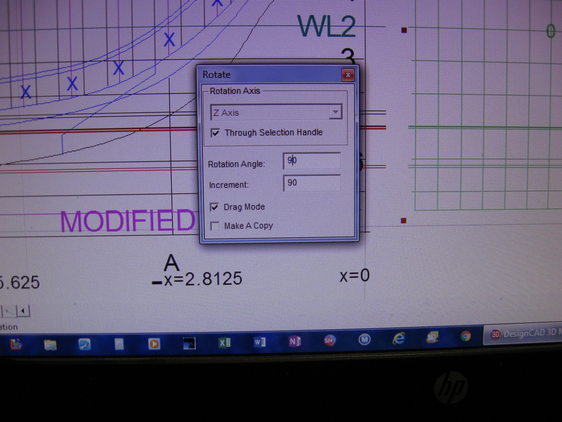
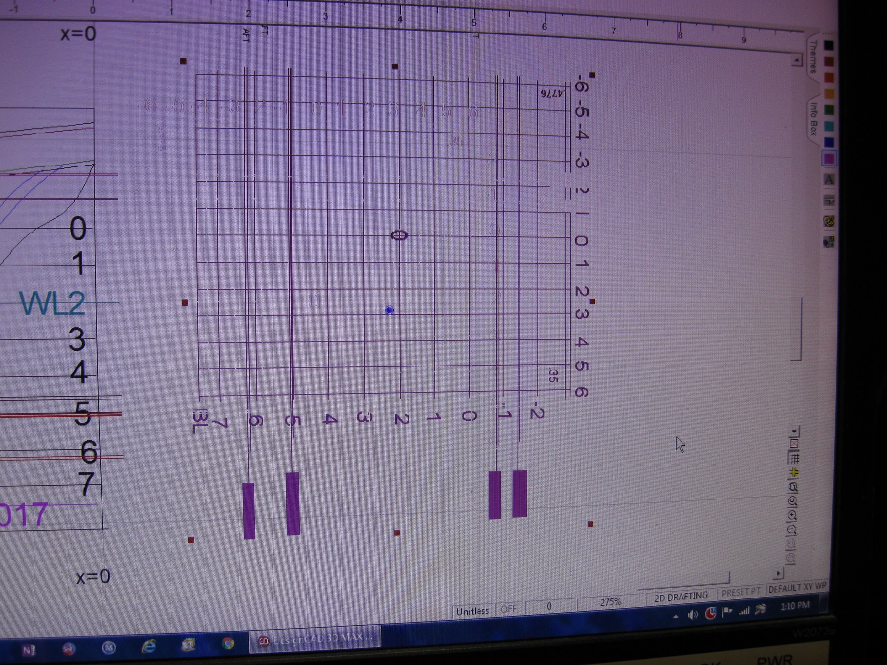
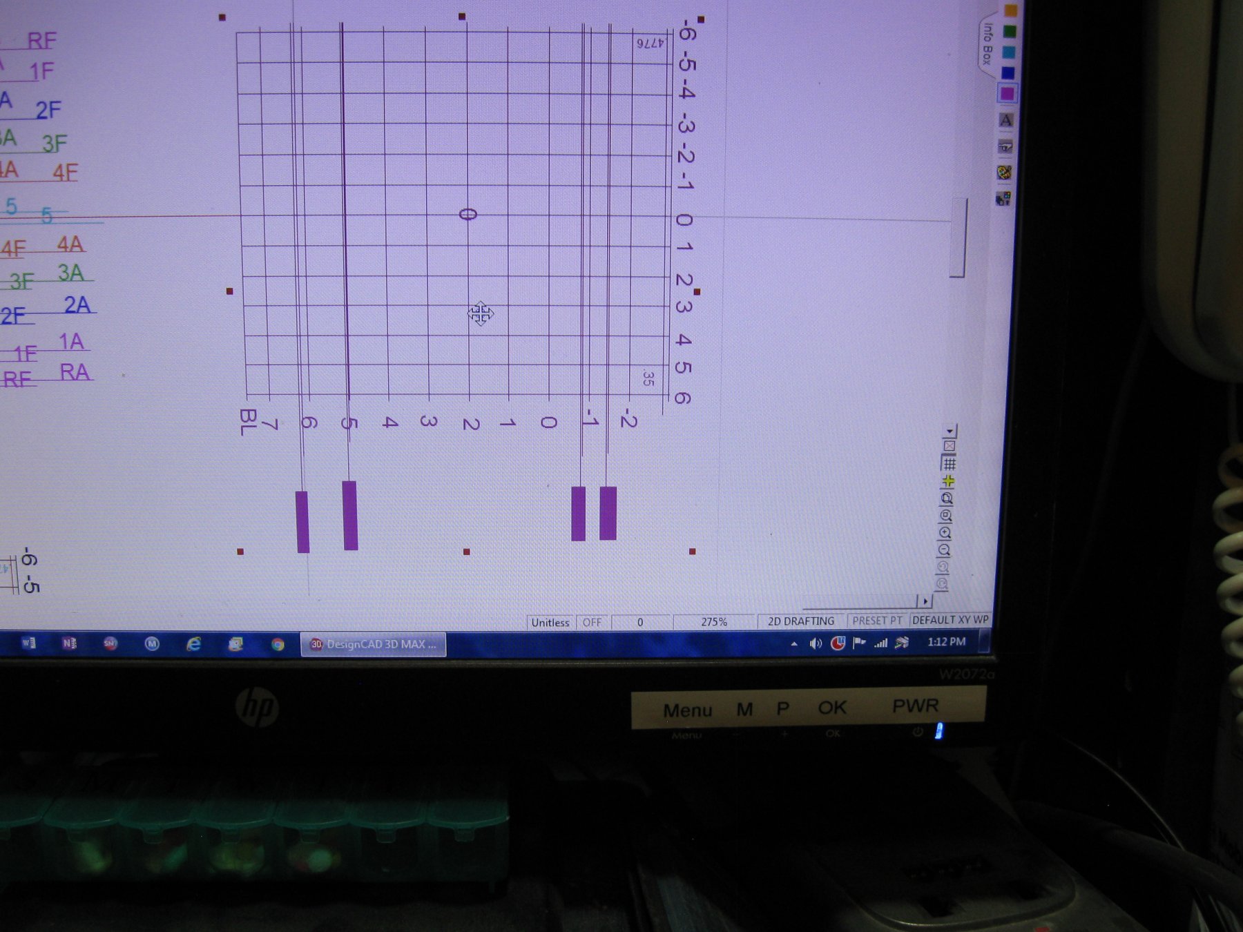
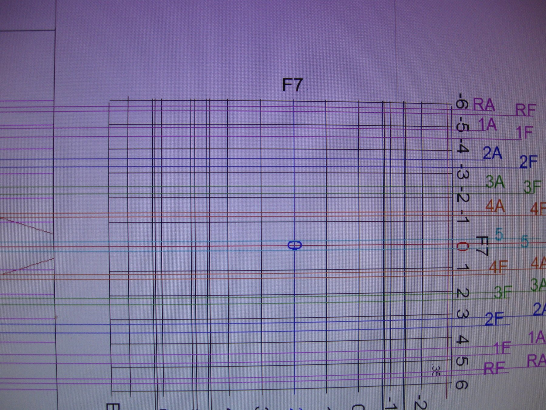
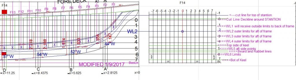
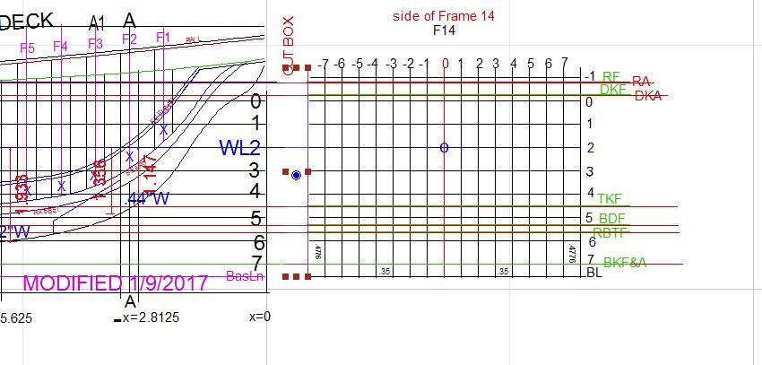
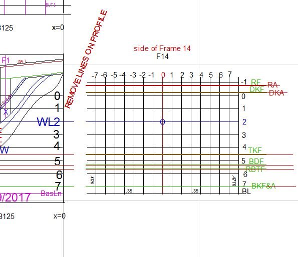
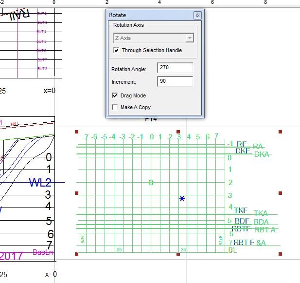
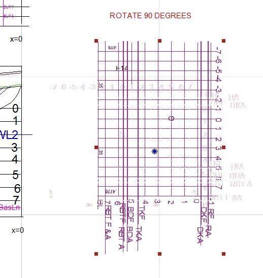
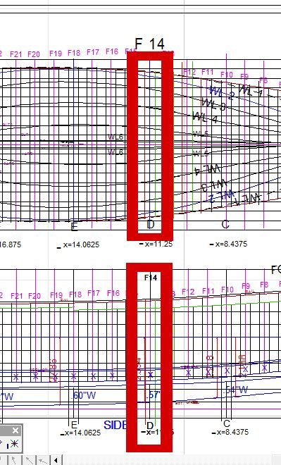
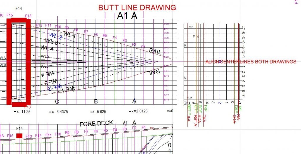
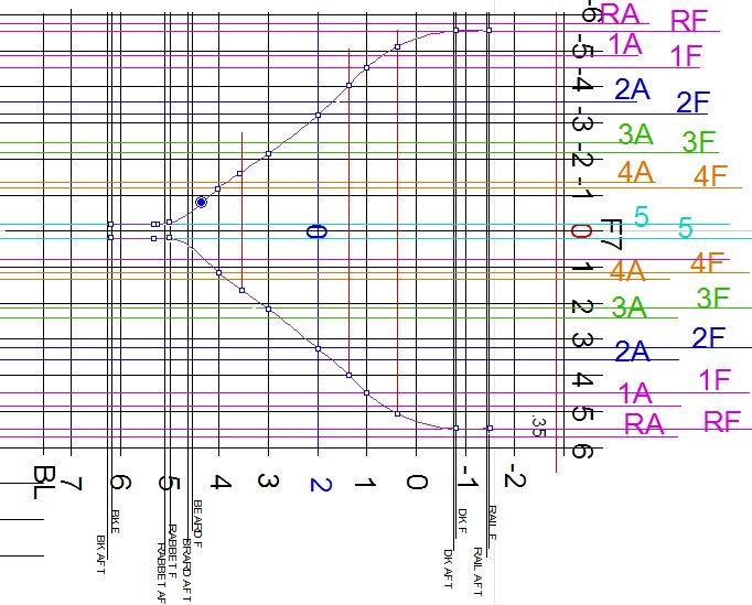
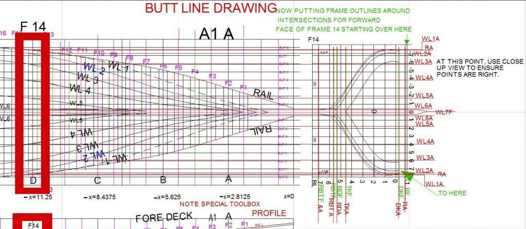
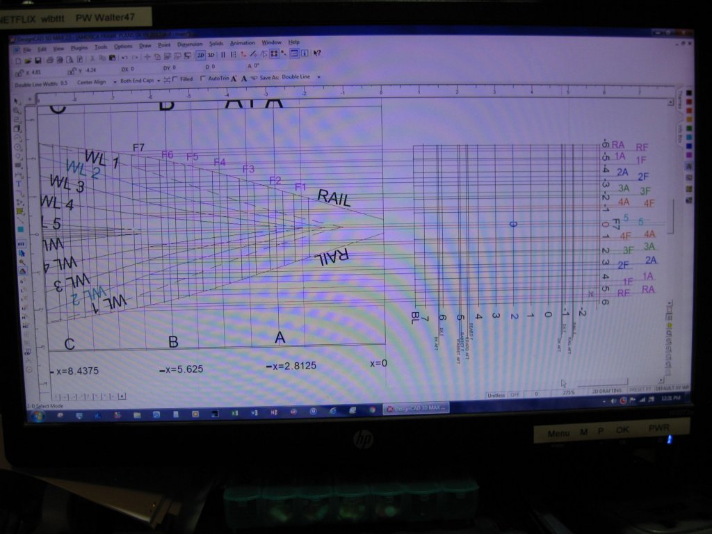
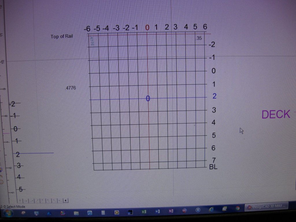
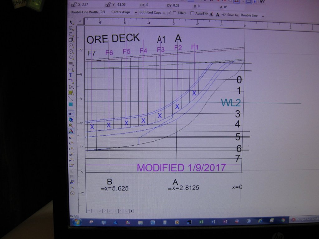
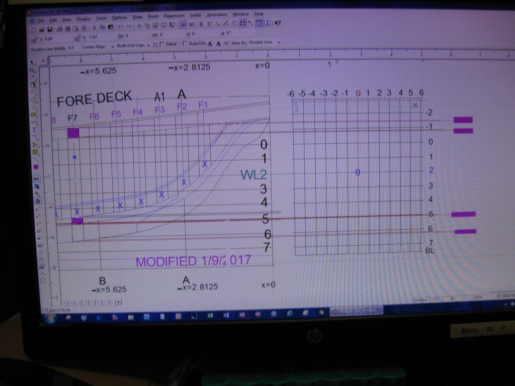
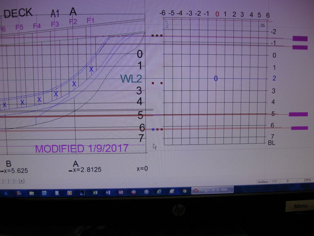
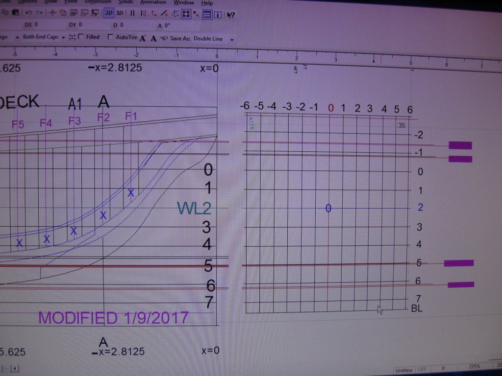
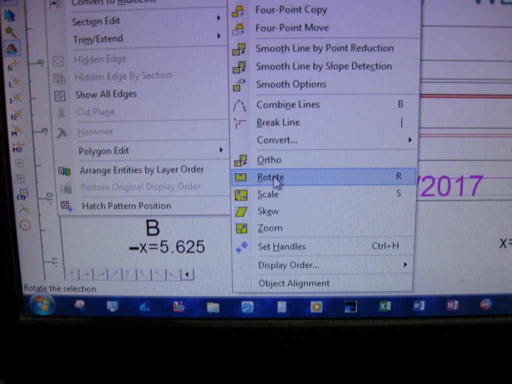
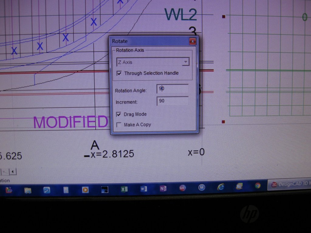
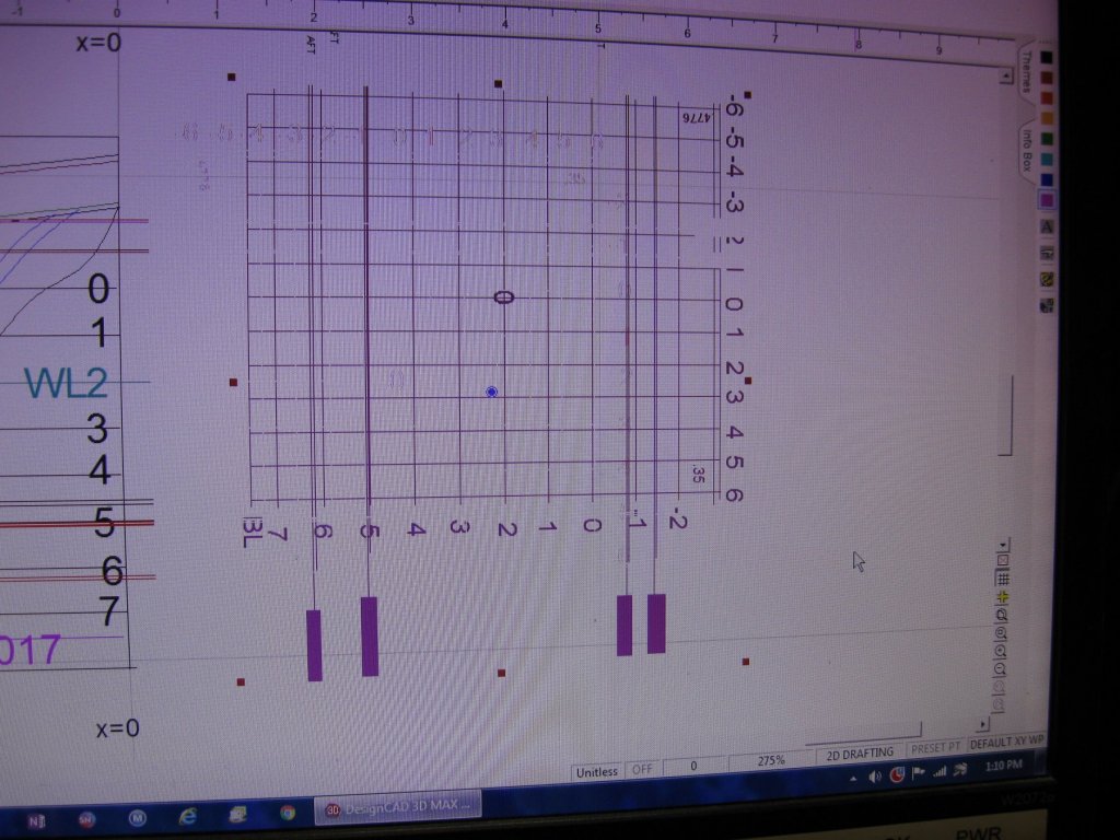
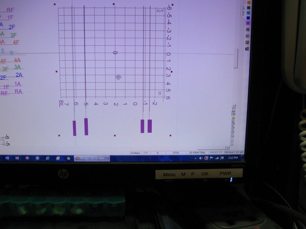
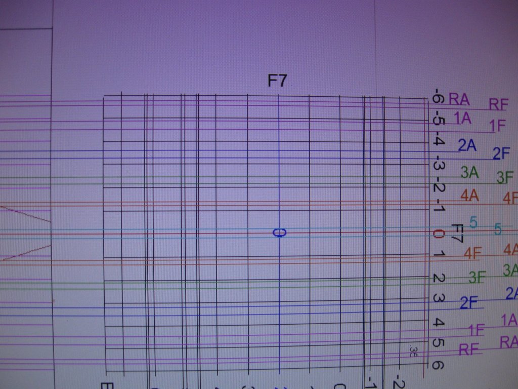
I have been busy creating Windows 7 clippings from my CAD program to explain my steps in producing each frame. I have made comments in TEXT BLOCKS to explain the different steps. I found these clippings to be more economical size-wise than the former pictures. These first few show the front of the side or profile view and a grid for the drawing of the frame I will be working on. I have made Red color fill blocks at the top and bottom of the frame I will be creating. The Profile view will have orthogonal lines made from intersect snap selections and will be pulled out across the F14 block to give the elevation on the grid for each of the pertinant information mentioned in the purple text to the right. I have the waterline for the F14 grid lined up exactly with the waterline of the profile view so that the snap to intersection point on the edge of the profile showing the frame edge will have the line across onto the F14 FRAME drawing. Later I can use snap to intersect at each elevation to prepare the drawing for more cross lines from the buttock line drawing, which will make intersections that I can snap to a curve line to make the shape of the former. The green side of the F14 side view will show on the grid, then I used a cut by block selection to leave the green lines which is the foreward face of F14. Then I removed the green lines from the profile drawing to eliminate the clutter of too many intersections for the after set of lines which will be red. Then after doing the AFT set of lines in red, and carefully labeling the type of intersections for both the foreward and aft sides of the frame, I have cut the lines between the views again and removed the red lines from the aft side of the frame in the profile drawing. Next I am ready to select the FRAME drawing and rotate it 90 degrees right so I can get ready to move it up to the Buttock Line drawing to continue with entering more lines from the other direction. These will provide the vertical intersections on the first set of lines. Here I wish to advise that since it is very easy to get off line of the frame you are trying to make, I recommend a marking of some type to keep you working on the correct one. I made two rectangles off the side of the drawing and filled between them to create a frame of color that I could use to position on the buttock drawing frame to keep me from getting information from the wrong frame. See the next illustration: Now you move the rotated Frame grid and align the centerline of that one to align exactly with the butt line drawing as in the next illustration. On this BUTT LINE drawing, you go to one face of the frame and snap select an orthoganal line from each butt line intersection over the Frame grid and mark each one with it's label. On this next illustration, you can finally see how all these intersections can come together for the Green FOREWARD face of the FRAME to create the frame outline. you can see how important it is to have each one of the intersections on the various lines can be to get the right shape. The lables at the bottom of the above drawing beside the frame WATERLINE NUMBERS, can help you tell where things like the Rail, Deck cutline, Beard, Rabbet, and BOTTOM of the Keel help you establish the limits of the elevations on the grid. Then you can do the Red After side of the frame creating the lines so you can get the amount of curve on the edge of each frame for a FAIR shape. I hope this may help others to be able to create CAD drawings from the relevant drawings of the plans. It took me quite a bit of effort to get all these steps developed and more importantly in order so you can follow the ideas through. Best of the day to you all!


-
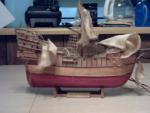
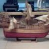
Well, I now have 12 of the 31 frames lofted so I can print them out. Each frame will be 3/8" thick with a like amount between each frame. I know about the percentages of difference, and have decided for this one, I'll do them this way. I am going to make the first batch of frames on plywood, then make them so I can have the Ply frames to check the fairness. Later I will make individual 7 part frame members to make them with wood. When I finish I will have a wood keel with the notches for each frame, and built up frames. I hope to get to see what it will be like to construct the boat as if it were a real one. I will be doing side trips for my own enjoyment of the adventure just to see what is possible. I think I may try my hand at making all my own hardware and deck furniture. Sounds like fun to me.
-
I have been burning a lot of midnight oil the last few days. I now have the F7 shaped and saved, and have been refining my routine. It is getting better all of the time. I have also moved some of the command Icons to where the ones I use are close together. That has helped quite a bit. I am going to try to do a few more before I try to chronicle and picture my steps. The first try was not up to what I wanted, so I am still learning.
-
The pictures are mostly in order, but I can't seem to do explanations except before the full block of pix. Anyway, I hope that you can follow along the progress.
-
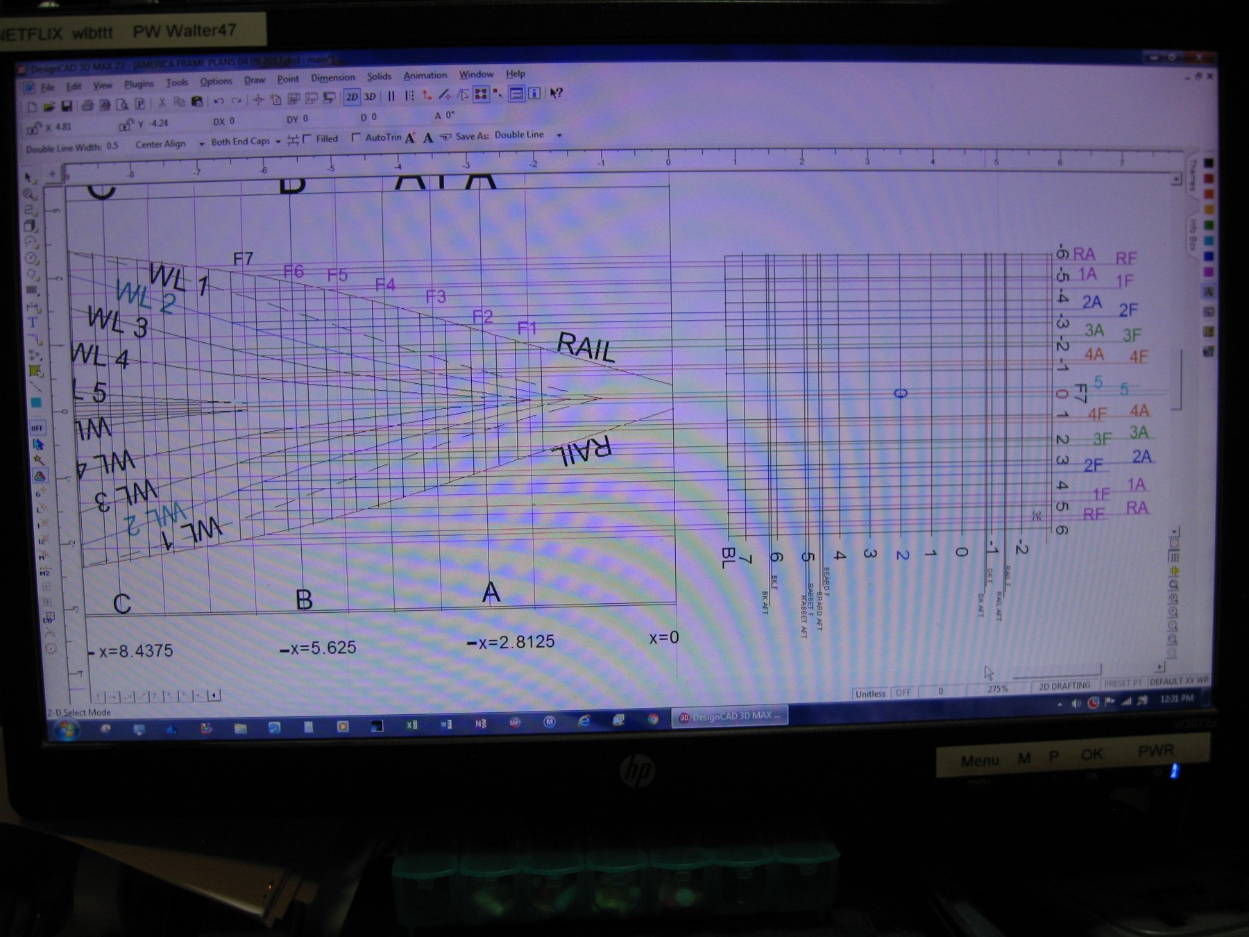
Since I can not break into using 3D on my CAD program, but I was fairly well versed in DesignCAD, I am planning on using the grid lines for WaterLines of the Profile or Side View, and the vertical grid lines and Water Lines on the Buttock Lines drawings, and the other Cross Body vertical and horizontal lines on the Body plan and the shapes described by the Waterlines on the Half Breadth Plan. I will be using ORTHOGANAL Lines and the Gravity, Intersect, or Snap to Line commands for almost everything to make the transfer of the points from one PLAN to another. By using the snap features, and pulling out orthogonal lines to my carefully aligned frame grids with the first half of the data put on them for the heights above the Baseline, I should be able to get a fairly true rendition of the needed parts. I now have almost 7 Frame Plans with the Forward facing lines, and the After frame face lines. I will be developing all the waterlines that create the shapes of the Waterlines to create the points for all the frames or Sections otherwise known as the bulkhead shapes at each frame station. I already tried using the Body Plan, but will be comparing them against what I get by lofting the frames off of a consistant set of elevations and half breadth plans. I had hoped to be able to learn the commands to do all these in 3 Dimension, but have not been able to even get close to repeatable success. Therefore I will be using all I learned about 2D, and thought to offer my methods for others who may be having similar problems. The first splice I make will be to put the grid which will eventually hold my frame shapes up to the Profile or side view drawings which all will use the Water Line of both parts to get all my deck line, Sheer Line, and all the angles of the keel facings against the frames. Once I get all of those points set I can part the grid and rotate it so it will line up the Waterline with the Centerline on the Buttocks Plan. The places where all those intersections occur will give me the shape of the bulkhead or Frames, Front and back sides of each frame. This Picture list of the initial CAD screen drawings I have made, will be a start to help others get some ideas to use 2D CAD. I just hope they will be clear enough. I hope to blow these plans up to a bigger scale for Radio Control eventually. You see, I love building things even at my age, but have enough boy in me that I still want to be able to play with the toys I build. #1601 Butt Line Plan. Including Rotated Grid 1602 Master Grid copied 1603 Master Grid Main ready to receive data points. 1604 Side Plan of Frame Positions on it’s grid. 1605 Master Grid aligned to Water line of Side Plan. 1606 Use Edit cut box to separate transfer lines and grid. 1607 Grid separated from Side Plan. 1608 Select grid and rotate it to align with But Plan carefully aligning the Water Line of grid with the Center Line on the Butt Plan. Either have the rail line or the Keel base line toward the end of the Butt Plan. On this page, the Rail Aft and Foreward for Former 7, have been fixed with pink Ortho lines which will be the top aft position for the fore and aft positions on the port rail. I marked ID labels at the far right and I will find the right side vertical lines for each set of lines, and use Intersect positioning to put them on the appropriate position. After that I just have 9 more positions to mark on the port side of the former grid, then 10 more for the Starboard side. Once that is done I can cut the lines between the two parts and use Click attach by intersection down along the side of the former for front and back sides, for port and starboard. It is quite cumbersome, but should give me accurate positions. Then I can rotate the Grid 270 degrees for an upright position, and I can go on to the next Frame 8.

-
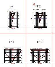
Well, I finally figured out where I was in the CAD work. I found a number of drawings that my computer saved elsewhere. I am using the plan drawings of the Buttock lines in stead of the section drawings which were on the plans. I think they must have been representative examples, because the bow frames I am getting by the buttock lines are quite a little different than the ones they show, and they make much better sense. A and A1 were side by side, A was concave curved from bottom to top and the next one was almost straight sided V. The ones I have gotten from the buttock lines have A with a outer upper curve with the concave below it. Then the A1 next to it is similar so they should transition into the outward curve on B section with the concave moving downward until it disappears. I have decided that that is what I will use for all the frame lines, and only have to use the lines at each waterline to develop the curves for each. I have the first two frames drawn out of 31 although I think I may create the front and back lines for each side, so I will have the taper for each frame. I am thinking on how EdT used marks on the frames for alignment of front and stern sides of the frames. Thanks Ed. I think my book on lofting has helped me quite a bit. Up until my study on that, I only had a so-so understanding of using the drawings. If I can, I will try to find a way to show how I am doing this for those others who can only do 2D, once I get the routine refined.
-
I tried to open my latest CAD files for America. I can't figure out what I was trying to accomplish. I need to get a printout of the latest Section drawings so I can begin to work again. DUH! Only problem is I stopped with something half done, and after months away, I can't figure out if any of the drawings are good or not. I am going to review my log, and try to pick up my memories of what I was doing at that time. How can I get so lost from what I was trying to do?
-
Thank you for your responses to this topic. I appreciate the variety of ideas shared here. That helps others to get some ideas of HOW TO do things in our hobby.
-
It isn't that she is really doing better, but since we are so far from any home health care, that she has been doing HOSPICE from my daughter's home. She hated being away from home so much that she was going to dump having dialysis and come home to live or die. I got the Doctor to agree to have her do dialysis just 2 days a week, which would let her have a weekend at home each week if she wanted. I really hope that will work for her, because if she stops dialysis, she gets too weak to even set up. She would not last long that way, and I cannot lift her with my torn arm.
-
Hello again, finally! I have been all over the state this past 5 months. After our son's death, my wife's condition went south. She has been doing dialysis in hospice at our daughter's since December. She just got cleared to go to twice a week which will allow her to come home at least some of the time. I'm getting the house all spruced up for her return this next weekend. I have actually been able to get some work done on the shop to get it towards functional for the first time since we moved here 21 years ago. I now hope to be mentally able to work on my new ship for a change. I am leaving Meridea for now until I can get some framing done on this America Schooner. I am fairing the stations to fit the 1/4" scale and then I will measure the points for a fair frame at each frame position using strips at each elevation line. That will give me an edge of frame line which I can use to develop each frame. I will use CAD to develop my frame patterns, but only in 2D, since I could not get my mind around using 3D. Thank you anyway, Ron, for trying to help me. I couldn't retain the "how-to" even though I managed to get the stations positioned fairly close in a straight time run. Once I got that far, when I tried to go back to it, I could not even remember how I got it to where it was. I guess I'm stuck with using 2D.
-
Thank you Mark. I know you have also had a lot of similar concerns in your life. My past experience in the Naval Yard shop only goes so far, because we seldom did new structures of boats. Usually we spliced in broken framework, and I understood how to do that. I have done pretty well with that, but if possible it would be nice to be able to take the tables to loft the frames. This is one area that would make it easier in the future to find out how to derive the shapes and dimensions using them. Since I mostly do my own plans, It would help to know what the expected parts do and how they are shaped. Previously, I worked only with how a patch must overlap, and how to maintain the strength of the frame being repaired. That way I will understand better how the CAD helps to show what should be there. I hope that I can learn it. Practicing the learning helps me renew the mental links that have been damaged.
- 208 replies
-
- 4
-

-
- meridea
- repair ship
- (and 1 more)
-
Thanks for all the likes, Mark and others. I have been reading through the lofting book, and putting some cross referencing on some things to learn more about. It has some terms for parts like HOG, for a part of the keel relating to the rabbet that I had never heard before except in referencing the distortion of the keel and hull. It relates to a special board to make it so the planking along the keel has twice it's thickness to seat up against. That would be a good thing to have for stronger and more water-tightness in the attachment of the planking. It only seems relative in smaller craft with not large keels, although I will have to follow up to learn more. The amount of work to get the table data is one of the things that my CAD program has been helpful with, however I can see that it would be very helpful to know how to use the table data when things just don't quite fit, although most of my scratch building did not have lofted drawings of any quality. I certainly feel that knowing how to do lofting could help me in the future.
- 208 replies
-
- 2
-
-
- meridea
- repair ship
- (and 1 more)
-
Thanks, Bob & Popeye I have been too disturbed and upset to concentrate most of this year. Now they are starting to find things they can do to help her, I hope to be better able to concentrate on something for a while at a time.
- 208 replies
-
- 4
-
-
- meridea
- repair ship
- (and 1 more)
-
This past half year has been tough. My son died in July, and since then, my wife has been in bad shape. Everywhere from 75-180 miles away. She is now on dialysis. I have put over 4000 miles on my vehicle trying to keep up with her. She could not even get to my daughter's for Christmas, because of weakness. Finally I am back home and the dialysis is helping her strength return a bit. She is still in nursing care. I am hoping she can come home sometime soon on home dialysis. Meanwhile I am "Home Alone". Maybe Now I can concentrate enough to get some work done on my model.
- 208 replies
-
- 2
-
-
- meridea
- repair ship
- (and 1 more)
-
I'm trying to get back into building. I got "Boatbuilding" by H. Chapelle, and "Lofting a Boat" by Roger Kopanycia. I hope to be able to learn more about what I may be doing wrong, or right in Lofting and building a boat. I have the second book already, and should have the first within a few weeks.
- 208 replies
-
- 3
-
-
- meridea
- repair ship
- (and 1 more)
-
Happy Birthday Mark. I hope you and Janet are having a nice holiday, and birthday. You are both in my prayers. We'll be sticking to the home front this holiday. There are a lot of people on the road this holiday, and I hate driving in heavy traffic. My best to you both.
-
Yes, Bob, that's the plan. I still have not figured out how I malformed that keel frame. Grabbing a line at the bottom and unintentionally moving the bottom closer to the top sounds to me what might have occurred, which was the inverse of what I thought had happened to the longer frames. Finding where the misallignment was has proved to me that I am still not good enough with even 2D CAD, and I will need to be very careful when drawing. Using the mockups was my old school acid test to see if I had screwed up, but now I know, and at least where I messed up even if it is still a mystery to me exactly How I did so.
-
Mark, I think I may just have enough for the new sections, I will have to use cardboard for the rest, but that works too. I can use the same keel (the newest one) I think I will use cardboard for the rest. If they come out okay, This build is ready.
-
Well, I finished doing all the dimensions so I can locate how far out the waterline to mark the curve on the frames at each level. I think I already did the butt line dimensions on my set of plans. If not then I will have to do those, if there are any points where they could add to the definition of the hull. I believe I should have enough. I am going to have to rest a bit while I think over where I would want to go now with the build. I am contemplating another mockup with these latest lines and figures to make sure I have them okay all over this time. It would sure save me some wasted wood if something still is not right, and I have already had 2 strikes in the department of planning and I can get cardboard from pallets and boxes from the local grocery store. I can just dream of cutting those frames and assembling them as if it was a real boat. However all that basswood came to way more money than I can afford to waste. I'm sorry guys, I use my site to put down the thoughts before I do them, I use it more as a tool to help me muddle things through. So If you read this and have a thought let me know. It wouldn't be the first time nor probably the last that somebody came up with a relevant idea in my build. I am not just building a boat, I am working on brain process repair in the effort. For awhile, I couldn't even do anything constructive with my mind back not so many years ago. I am also working on piecing my thought processes back in order. It has not been unusual for me to skip over an important process in analyzing a problem or process that I used to be able to do as a matter of course, before they finally found out that I had severe apnea and started my treatment. The doctors, with all their training, could not even tell me if I would be able to do any better than I could at that time. I have found that if I can re-establish a link with an old set of memories, that often they will break through and become useable. However, It is not without some effort and I often have gaps that need worked through. I have relearned an awful lot, but I realize I have a long way to go. I often remember how easy it seemed to come to me to do a task or build something, and I can still remember NOT being able to do so more recently. I do love building models of things, though. I wish you all the very best.
-
I have been hard at work on the America Plans. I went back and am verifying every waterline at each station off the original plan, and making myself a table of the data. I have the spacing and size of material for each frame established for my boat. As soon as I can finish dimensioning my plan completely, so I know it should match the plan drawings, I should be able to formulate the shapes of all the frames in between, including the angles of taper for each one, so I won't have to oversize too much and waste a lot of material. Once I can get the plan I have made In CAD verified to dimensions, then I can get to work lofting the frames in between. Then, and only then, will I be able to get to work on the actual frames. Right now I really don't have anything I can show except the mockup with the stations and keel. I have finally drawn in the STERN parts although I still have to determine their material thickness. I am going to do a box around the rudder for the brass sheath to fit in so the rudder can have resistance to water entering the frame around it. I figure to put a small "O" ring at top and bottom of the rudder with a washer over each end, so I can pack the shaft with vasoline for lube and water protection. The box will become a part of the horn timber and form the bridge around the shaft to the keel framing. I wish I had done that on my Meridea. It wouldn't be an off center hole mousing up the alignment of things. This old codger learns another thing the hard way!
-
Mark, nice try. It was still cool in effect, even though it didn't quite meet your fit standards. The redo is bound to please.