Walter Biles
-
Posts
356 -
Joined
-
Last visited
Content Type
Profiles
Forums
Gallery
Events
Everything posted by Walter Biles
-
 Beautiful job Bob. Wonderful detail. Keep up the good work.
- 348 replies
-
- 3
-

-
- pequot
- cable ship
- (and 1 more)
-
Well, I am backing up again. I found another error in my plan. I lost some height in some of the waterlines on the keel plan. That was why I was having to cut down some height off the frames. I am glad I found that. I thought I had some of the frames in the midsection stretched in height somehow. I am getting ready to cut a whole new set of keel and stations. I just got myself a new 1" x 30" upright belt sander with a 5" disk sander attached. I spent the day setting everything up on it, and found a problem with keeping the table angle from changing. I cut myself a brace to hold it from moving when I am working on square sanding. I think I might make a better table angle mechanism. I like the layout of the thing, but I will have a few concessions to make. It should still help me work truer. I am backing up to my earlier station CAD drawings since They were closer than I thought. I just had about 3/8" error in height on the keel and uprights. It is sure amazing what you can find out about a drawing plan by doing periodic mock up models to test out it's accuracy. You can see how I had trimmed height off of D through G stations in the lower post #47. It was near the bottom of the frames were where the lines were closer, and I hadn't caught it before. I don't know how I did that one. At least I have it corrected now.
-
Thank you Mark. I have been doing a lot of work on the plans. Since my plan is to blow up the plans to get a near scale to my Meridea which is about 1:13 if I was guessing correctly at it being nearly 38'. However, since it was between 1/3 to 1/2 the length of America just beyond where she was tied up, she may be closer to 50' and if that is the case (my memory is no longer clear on the comparison) I might just double America's size to 50" so she won't be too big to handle. My Meridea is 34" She would still be bigger than scale with America. But they should be so pretty together on the water! I just hope that I can get the RC to work right. That is something I have never tried before in this application of boats. Thank all of you for your likes. I am beginning to get back into the spirit of building again.
-
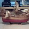
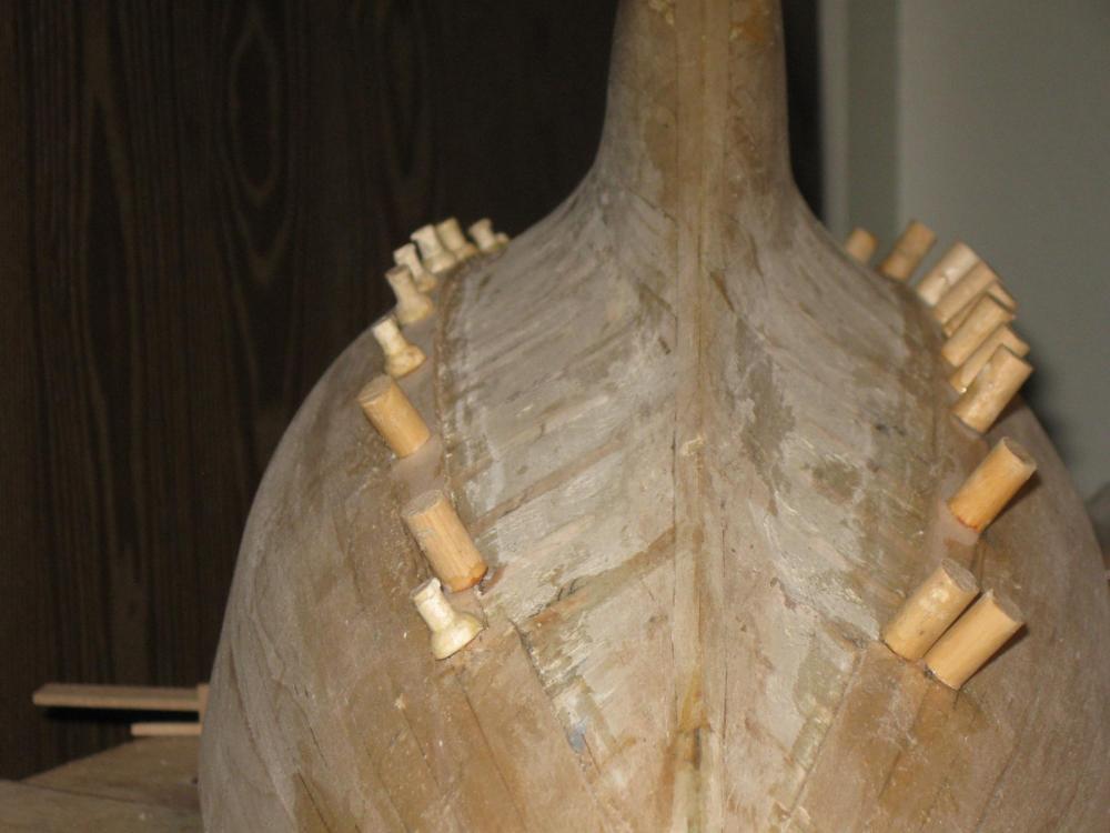
Here are the last two planks I added to the Meridea. I now have a different camera which takes much more detail, once I finish learning how to work with it.

- 208 replies
-
- 4
-
-
- meridea
- repair ship
- (and 1 more)
-
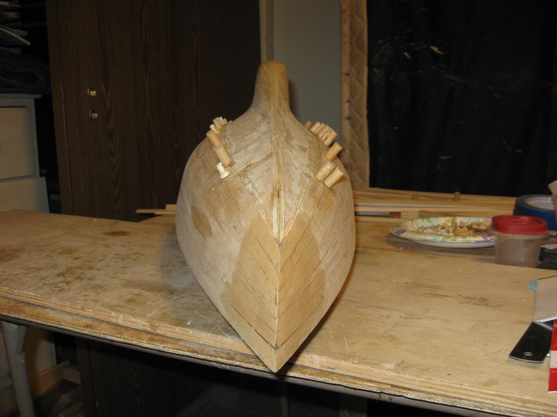
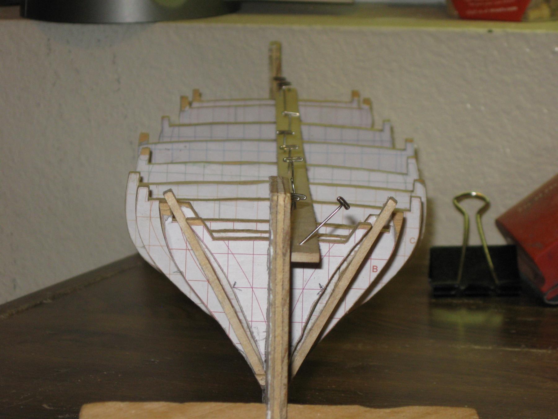
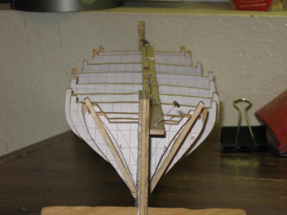
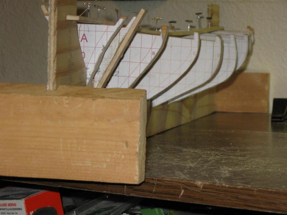
Here are the more recent pix of my preliminary trial fittings of patterns to a plywood keel to test the fit and alignment of the Stations I generated by DesignCAD V23 which is my most recent version. I need these patterns to fit correctly so I will be adjusting the lines on the stations until I get a good representation of their shapes. Then I will fair these and start adding thin pattern stock at Frames 1-31 around them and then when those are fair, I will replace all the stations with frames, and create a new keel and start putting frames together. The model which I will be building will be based on the Blue Jacket 1/4" scale POF America plans. I hope I have caught all the corrections to the shapes to fit the keel drawing I made from their plans. I found that the Station drawings needed adjustments just to line up fair, and I am not sure if it was their drawings, or the drawings I made from them. I used their plan measurements from main reference lines for all the stations fore and aft of the plans to do all my CAD input. I had to fair them quite a bit, and decided to do this pattern check trial to see how close they come to lining up. I will Invert my frame holders and take a few more of the inverted hold to post later.
-
I have finally made the adjustments to the offending stations. Things seem to be lining up pretty well now. All the water lines fall in line, and the bottom ends at the proper line for the planking. I keep trying to learn the terms for those planking lines, but they keep escaping my memory. Dang leaky short term memory! At least I can work on models again.
-
Bob, I do believe that they were. They had responsibility for national shoreline defense. They probably also were assigned a certain amount of soldiers to help with things in case it became a shooting war at the home front until the regular forces could be adjusted to cover in that instance. I believe they also had responsibility for mine laying for defense of the home front as well as patrolling the shorelines. I am pretty sure I read something about some of their actions in the Atlantic earlier in the war. After all the Germans were patrolling right off our shores at the time. They sank shipping right outside our shoreline, some even in sight of the land.
- 348 replies
-
- 2
-
-
- pequot
- cable ship
- (and 1 more)
-
Try as I might, I have not been able to break through into repeatable and more importantly accurate use of 3D CAD. I am going to take my 2D drawings, and try to build an inexpensive keel of plywood, and install plywood stations with the water lines marked on all of them, and build a mock up of the frame. Then I will install some material of as yet undetermined material for using strips on the waterlines to determine the locations and dimensions needed to create each frame between the stations which I found had a uniform spacing, and make the frames to fit in a uniform spacing between them. In stead of 32 frames, I will be using 31 so that I can get them uniformly spaced. I doubt that it will make any difference in any great way. I will just have to make adjustments for the differences if the plans call for bitts or any other deck feature on a specific distance from the bow. I figure if I can work the boat this way, it will still be a worthwhile project. I have been at this CAD 3D long enough. I will find a way around it.
-
The steel does not have to be hard to begin with. With a good torch, I did two chizels out of 3/8" iron square stock, then once I had worked them on an anvil after each heating to a good bright red, and got them shaped the way I wanted, one straight with a straight curved tip which I could curve up out of a cut, one of the millwrights taught me about taking a good can of oil and with heating and quenching about 10 times and then using an oil stone to smooth them out, I had smoothed them out on both sides where they were a good polish. Then I did another couple of heat and quench on each of them Then I used a leather strop just like the barbers used and stropped them until I could shave with them. By the way, most leather has a rougher but softer side that is good for the initial work before finishing up with the outer smoother side. The process is called case hardening. The oil quenching makes Carbon and Hydrogen go into the iron, making it very hard so it will hold an edge for a long time. After I had the edges shaped and before the final hardening, I ground the handle area to fit into a couple of wooden handles for files. I still have them, after 40 years. I need to reheat and requench them a few times now to make up for what I have ground off at the edges with the oilstone and stropping so my case hardening goes back in from the faces like it was from the first finish. Even those nails can be case hardened that way. I used vice grips to clamp the work so I could avoid getting burned, even through the leather palm gloves I used. Also leather apron, and a safety shield to help keep any slag sparks from getting where you definitely don't want them to go.
-
Popeye, No pix as yet. I have not had time to take them. Yes I had the CD for the download program, but the old computer no longer has the drivers it needs, nor can I get them anymore, and since the newer computers won't accept that program for downloading, I will have to use the SD card for transferring the poor pix it can take. I am getting my new computer up to run the newest version of Designcad 23 that I have, so I can get some frames designed for my America ship model. I did get the glue for planking finally last month, but it still waits. The plans from Blue Jacket that I got quite some time ago, have never gotten onto a computer that stayed up long enough to do anything with them yet. I like this new DELL with W7 on it. It seems more robust and stays out of trouble much better. I had one setback with it, and had to backtrack to an earlier restore, but never got my CAD back on it until this week. I lost the files from mixing the thumb drive I had them on with my backup file from the HP, and have to redo what I had up to that point. Anyway, I am working on some plans again, and hope to get the slip mate to Meridea started again. That HP fiasco with W8.1 just about put me against the wall for awhile. That computer now has W10 on it, with not much else left. I did get it up with my financial program where I can use it for a backup for that, but was too discouraged to trust it even for that. It mostly takes up desk space, although I sometimes watch movies on it. It seems fairly good at that. I do have most of my tools returned to my work room, now. I am hoping to find a better digital camera system so I can take clearer pix of the models. That old 2MP camera didn't have much facility for close up pix. I am looking to see if I can find one that I can control Depth of Field and aperature (spelling?) and still have crisp looking pix. I have been looking at what is available, but might have to go with a used one, slightly older. Before, when I had a good 35mm film camera I had started getting fairly good with stuff like that on it, but I need something digital so I don't have to pay processing all the time. In fact I can't remember the last time I had film developed on that old one. I lost track of it using the little digital one for taking pictures of the grandchildren. In fact I think it might have been disposed of when I moved to this house. At that time I was unable to think clearly, and may have given it away as something I would never use again. I lost so many tools that way. Anyway, I am doing some model work. Just nothing so far that I can share much about.
- 208 replies
-
- 4
-
-
- meridea
- repair ship
- (and 1 more)
-
I found out that my camera download program has lost support, I can no longer download the usual way from the camera to the computer. However, after much searching and with the help of the neighbor, I found that I can pull the mini SD card out of the camera, and with an adapter, I can read the menu of files to move them to my Pictures files. Yay! I won't have to buy a new camera just for that. Now I can get back to trying to get a little something done.
- 208 replies
-
- 3
-
-
- meridea
- repair ship
- (and 1 more)
-
I did need to get some new TightBond 3. I now have 1 more plank and a 1:2 start on the next level on each side. I am still having to try to find things I need for the job.
- 208 replies
-
- 3
-
-
- meridea
- repair ship
- (and 1 more)
-
Thanks Popeye, I got the work table cleared off, and now have to find where I was using the rest of my tools for some other task, so I can start getting set up to begin work again. I suppose I should start with some current status pictures, as a beginning point, if I can find my camera. Ah! Found it. Now just to find the rest of my hand tools, and those riffle files and dremel tools. I hope my glues have not all dried up. I may have to do some shopping for fresh adhesives. At least my planks are all cut to rough size.
- 208 replies
-
- 4
-
-
- meridea
- repair ship
- (and 1 more)
-
Thank you Michael, Your comment about just getting something started sounded quite true. It helped me get started again. A step at a time. I am slowly building my enthusiasm again. The more sorting things out of the mess, the closer it looks to do-able.
- 208 replies
-
- 4
-
-
- meridea
- repair ship
- (and 1 more)
-
Thank you all, I did go in to the hobby room and make a start. I had to put some things back together on the desk, and that makes some room on top for some sorting and storing. I still have a card table stacked high with I am not sure what, but it is a start. If I can get the boat moved over to there, so I can start locating my tools again, and find out what I still need to clear off so I can get back onto my work table, then I may be able to start, if I haven't moved too many of my tools back out to the shop that I might need. It is looking a bit more hopeful. My memory is still poor, and I only finished half of the shop bench repairs in the garage, so there is still much to finish before out there is usable, but I am going to work inside when the heat of Arizona is heavy on the land. Once it gets hot out there it will be just as unusable as when it was freezing the last few months. The shop is not heat nor cooling friendly. If I can get some sheets of insulation to install in the walls and ceiling of the garage, it might become some better. I don't have anything big enough to cool it or heat it enough to make it comfortable to work out there unless the outside weather is about right, which is hard to catch just that way. I used to have a wood stove in my other shop at my former house, and the two story house shaded the garage starting a few hours after noon. I used to be able to work in there 8-10 hours a day, but this one faces the sun all day and won't cool, and there is no insulation to keep in any heat during the cold part of the year. I have been watching the community bulletin board for an AC unit I could install in the back wall, but have not found one since I started watching for it. I did get some 2" foam sheets put in the metal panels of the roll down door a couple of years back, that does help the afternoon sun from radiating in through into the garage so bad. Well I am getting ready to get back to work on the Meridea, at least until I can seal it up to float. I still have some rigging to do down in it's innards to make the sails work. I am glad I left it where I can get most of the cabin roof open for working in it. Once I get a chance to learn what will work for sails control, I may just build me another one without so many mistakes in it. It has definitely been a work in progress, and a sort of trial and error sort of thing for me. If I can ever get it working nicely, I would like to offer the corrected plans up to anyone who would like to do it. It could be a very nice looking boat if someone can build the railings like they originally were. I have learned quite a bit about it's structure since I started on it. Although it was originally a fiberglass hull, I had to convert it to a wood frame, and ran into several complications with that, which left some work-around errors in mine. I also did not have the actual waterlines right, and had to build out and downward to get the proper waterline back up out of the water when I tank tested it. It would have been too low in the water, and probably unstable where the first set of lines were. I like that I have the cabin so strong, but fully capable of being opened up. I am thinking I would like to remake the masts so the sails could be raised through the masts right from the controls. I feel that was the intention of the original build. I think it was designed to be operational by one or two persons at most. A test-bed to sail long trips, with a minimal crew. I would like the model to be similar to that. Then I would have accomplished what I first wanted when I took her lines that day in the basin.
- 208 replies
-
- 5
-
-
- meridea
- repair ship
- (and 1 more)
-
A brief update to my life for my friends here. I check in from time to time. Family events of the holiday caused total chaos to my build setup. I haven't gotten it straightened out yet. I still have 4 or so planks left on each side to finish the planking. Since Linda's health has stabilized last August, I have been taking time for my health getting reviewed Since September. . I have been getting my diabetes under control, and I just went through nasal surgery in Feb. Oh! how nice to be able to breathe through my nose again. That is a lot better. My time has been overloaded lately, trying to get my health back in hand. Although I have thought about working on something, When I find the pile of disorganized stuff in my workroom, it gets put off. It just seems too much to think about to have to reorganize everything, and try to do anything. Maybe one day...
- 208 replies
-
- 3
-
-
- meridea
- repair ship
- (and 1 more)
-
Hi, Bob! It is looking pretty good. Keep up the good work. Walt
- 348 replies
-
- 3
-
-
- pequot
- cable ship
- (and 1 more)
-
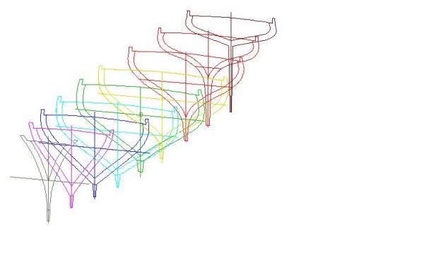
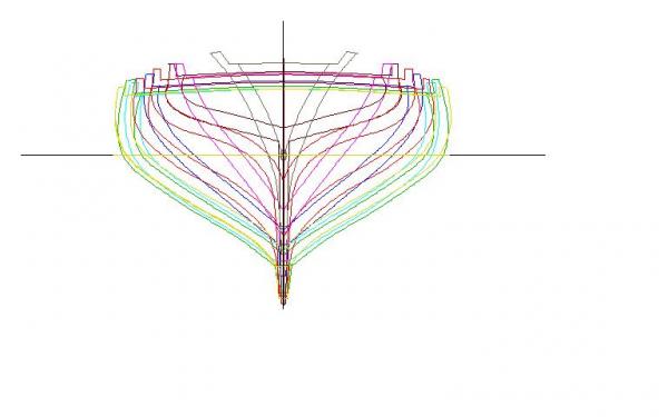
Thank you all for the likes, and especially Ron for his input. I admit I have retarded capabilities on DesignCAD. With Ron's help I have gotten further into 3D on my ship than I have ever gotten. I am now printing this section of pages so I can have a reference to work from. I am hoping I can follow his instructions through getting all my waterline grids onto my frames in 3D so I can begin to create the individual frames, fore and aft. I have a lot of studying to work through. If this works out, this will be a great HOW TO REFERENCE work on using DesignCAD 2D/3D to do framing. I have to admit that Ron deserves all the credit, due to his knowledge of this program, which I am trying to understand how to use even though I have had version 13, 14, and most recently 23 and have always had problems breaking through into using the 3D aspects of it. If he can coach me through to the ultimate printing out of my full frame set, He will definItely have proven his skill at teaching the program, as well as using it. THANK YOU RON!!!
-
Hi Ron, Thanks for all your help on the how-to-do of making the transition from 2D to 3D. Do you think it was a good idea to include the inside and outside of the frames as well as the waterline and centerline. I made each frame inside and outside then colored the whole frame with it's individual reference lines. Once I got all the frames done, I separated them by their color and then re-assigned all the layers into a different set of numbers, then I re-assigned them in sequence back down to the places where I wanted them to be in the Layer #s and named them all. Once I got all the different frames where I could turn off all other frames, I used xyz placement box to get them at the right position along the frame, then I went back to front view much expanded and positioned them over the 0 Layer so the individual frame and grid changed color when it lined up correctly on the vertical and horizontal Waterline. Once I got it where I could see XY in line then I went to make sure it looked right in the other 3D views. Then I turned that frame layer off and went on to the next Finally learning to use SAVE TO instead of just saving. Now I have all of them showing about in the right place when they are all turned on. Next I need to make all the other waterlines appear on the 0 layer, so I can start on putting in all the individual frames between that first set of Stations. I am going to have to have those waterlines to determine the size and shape of my individual frames showing fore and aft lines for each. If you have any pointers on how to get those waterlines to attach to the outside of each of the stations, That is where I think I would be going next. Does this sound about right? I probably need to learn something more about how to place points on each of the Stations at each waterline, so I can create the waterlines so they will show at each elevation from above, and from the side. It still seems a bit daunting to me. A lot of my time has been going to working on the church sign lettering. I had to get a plan for a router copier machine or jig, so I could put the old lettering over onto the new boards. It is over 90F+ in my shop in the daytime, so I have mostly been doing the noisy work in the cool of the morning, and working on the sanding and other quieter stuff most of the night. Plus I now have the engine out of my old pickup waiting on the engine stand all covered up. I think I'll let that happen in the later fall, when I can stand it out there. It sure is nice to have a working shop again. I have re-conditioned tools as I needed them, replacing all the frayed cords, broken ground plugs, and cleaning the insides of each electric tool, and re-lubing it to keep it from wearing itself out. I have re-ground my chizels and block planes to sharp and usable condition again, and I have room to move around in there which I never thought I'd see again.
-
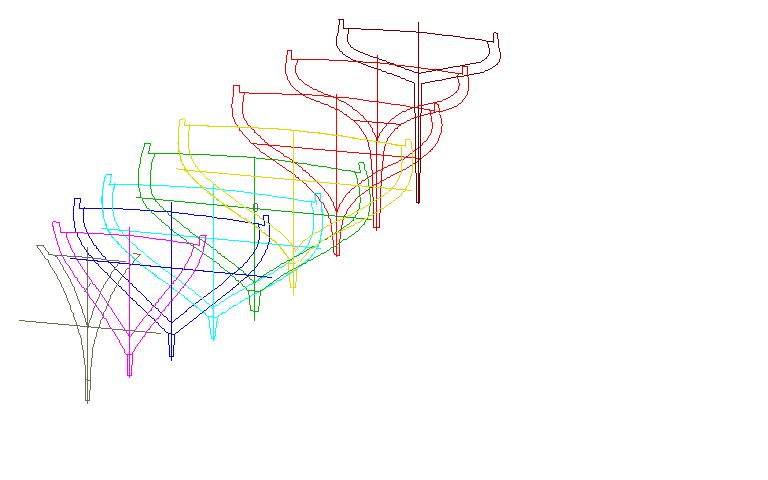
Ron, Here are the front, and the main views of my 3D frames How did you do those screen captures. I had to copy/paste to Paint, then save as JPG.
-
Thanks Ron, That gives me quite a bit to work on. It looks like you have done a pretty thorough job of it. Now I can study and cogitate for awhile, and see if I can follow everything okay. I have printed this log page 2 to here, and added the blown up pictures right behind each page with the text for clearer sight. I will see what I can come up with. Thank you so much.
-
Thanks Ron. I just don't understand how you are rotating each frame. There are oodles of commands I had never figured out before. Now I am having trouble on how to do things. If I can reach a break through and practice it enough I feel sure I can learn to do this. Once I get the stations in 3d, then I will have to create each frame position and shape. That will make another 32 times of practice. 42 times in all. Thank you so much for offering me your help. I didn't know when I got DesignCAD 3D Max, that it would be so seldom used between so many users of CAD. Luckily I do have version 23 to practice with. I hate having that computer so messed up that the only time I can use it is if it is off-line. I tried today to go on Utube to be able to hear the instructions for a certain tool construction, and I had HP, MS and my computer all screaming at me that my computer was putting my security at risk, so I had to log back off. The sound card has been blown on my old one for years. At least it's troubles are more passive.
-
Ron, QUOTE: After generating the hull lines, I go to 3D mode, draw out the base line, waterline, whatever you are using to determine the fore aft positions of the hull lines in the X direction. Then I rotated the hull lines 90 deg. so they run in the XZ rather than XY direction. Each "frame' is then positioned at its repective place on the reference line. you now have the 3D model of your hull. END QUOTE You say you draw the hull lines, and I assume the station positions along it You rotated the hull so the lines display in the XZ rather than the XY direction. I am having trouble figuring out what steps to do to do what you said. Could you walk me through the steps in the program?