Jackson7
-
Posts
189 -
Joined
-
Last visited
Recent Profile Visitors
1,623 profile views


-
 pankmeier reacted to a post in a topic:
HMS GREYHOUND by Jackson7 - Corel - Collaboration With My Past Self
pankmeier reacted to a post in a topic:
HMS GREYHOUND by Jackson7 - Corel - Collaboration With My Past Self
-
pankmeier reacted to a post in a topic:
HMS GREYHOUND by Jackson7 - Corel - Collaboration With My Past Self
-
pankmeier reacted to a post in a topic:
HMS GREYHOUND by Jackson7 - Corel - Collaboration With My Past Self
-
pankmeier reacted to a post in a topic:
HMS GREYHOUND by Jackson7 - Corel - Collaboration With My Past Self
-
GrandpaPhil reacted to a post in a topic:
HMS GREYHOUND by Jackson7 - Corel - Collaboration With My Past Self
-
Nirvana reacted to a post in a topic:
HMS GREYHOUND by Jackson7 - Corel - Collaboration With My Past Self
-
pankmeier reacted to a post in a topic:
HMS GREYHOUND by Jackson7 - Corel - Collaboration With My Past Self
-
pankmeier reacted to a post in a topic:
HMS GREYHOUND by Jackson7 - Corel - Collaboration With My Past Self
-
pankmeier reacted to a post in a topic:
HMS GREYHOUND by Jackson7 - Corel - Collaboration With My Past Self
-
pankmeier reacted to a post in a topic:
HMS GREYHOUND by Jackson7 - Corel - Collaboration With My Past Self
-
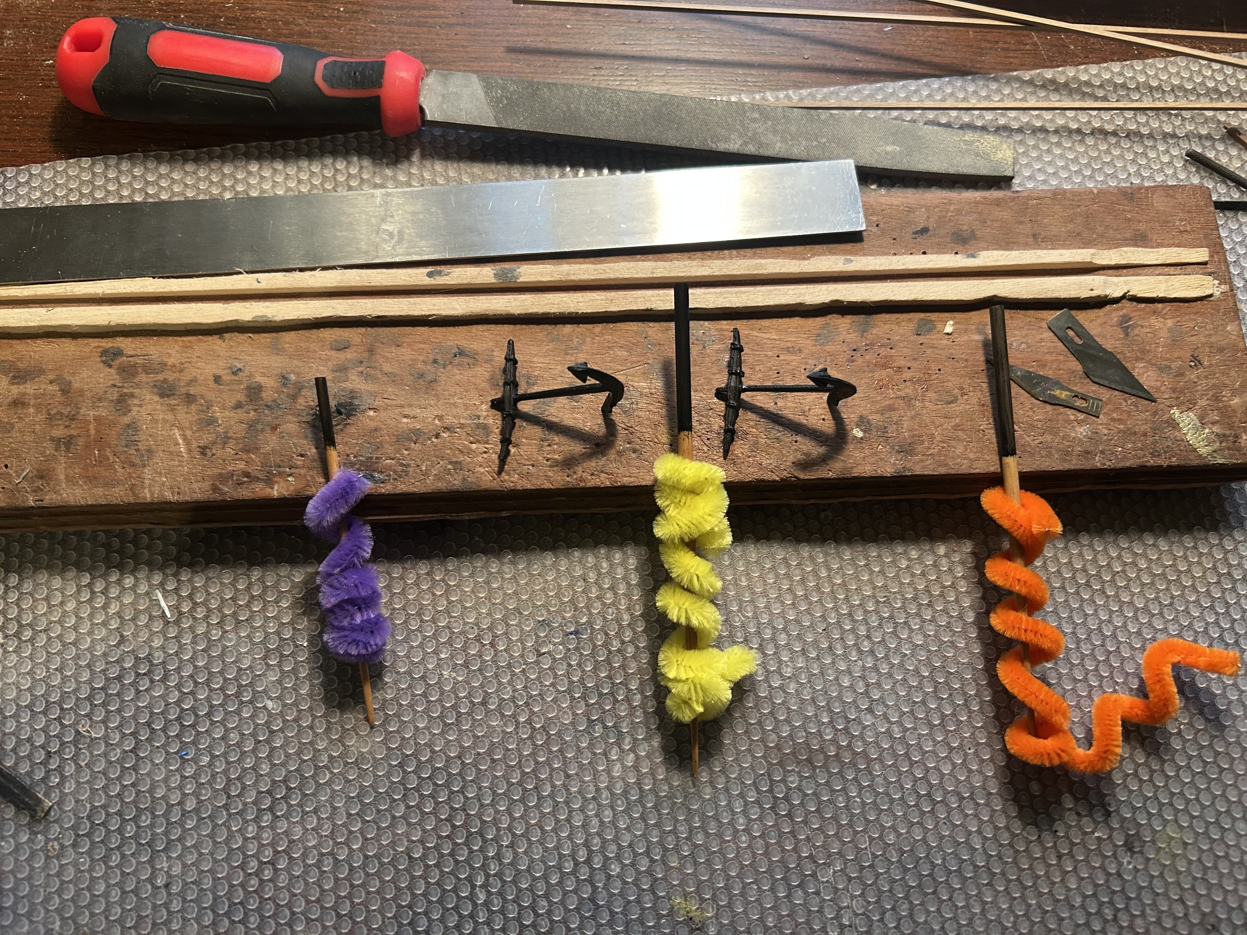
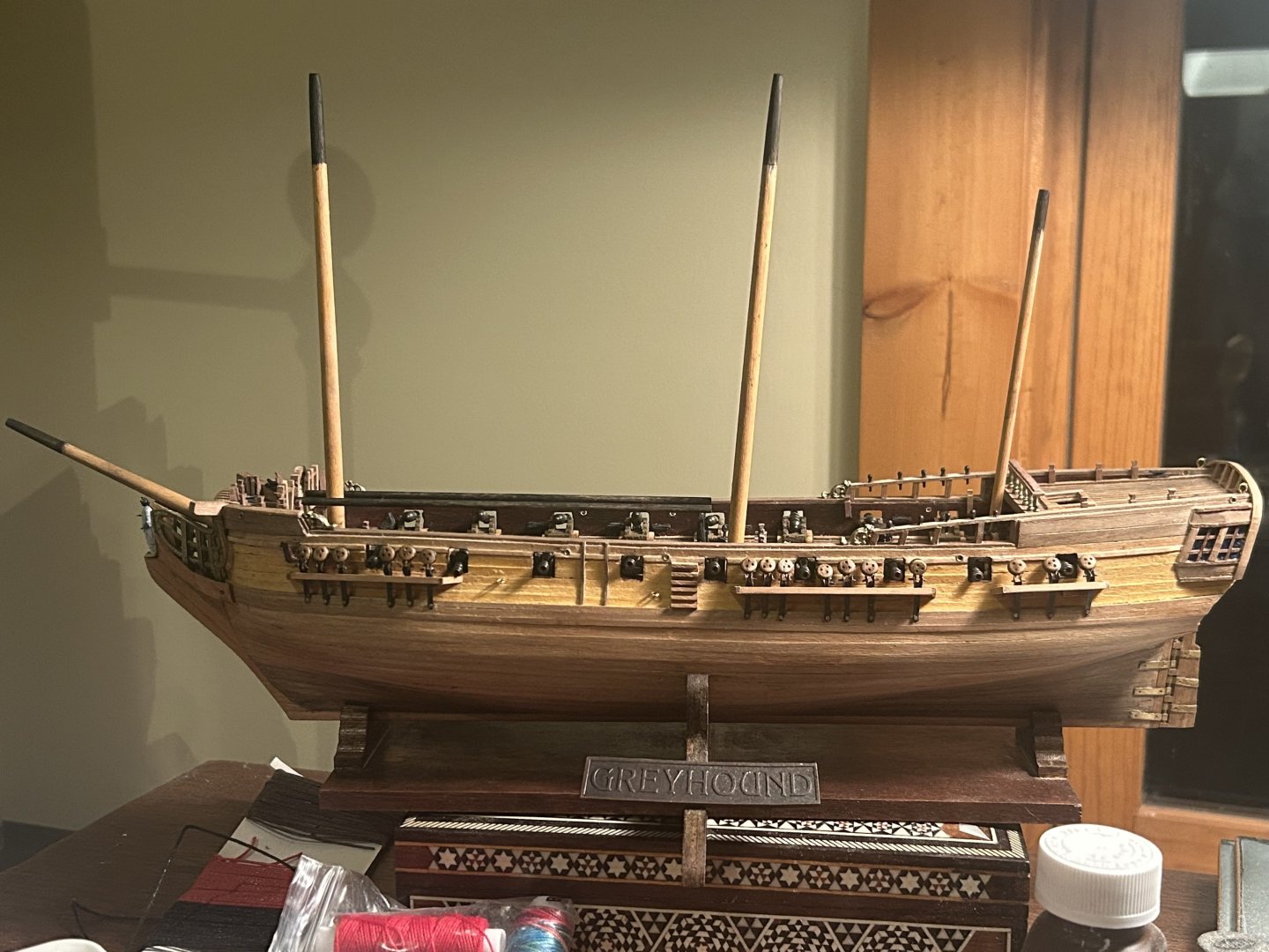
I've made some decisions. Here's the plan. I'm buying black line to do the shrouds from Amazon, along with some little brass hooks that will work to hold the anchor and other things of that sort. After I do the shrouds and other rigging, I'm going to do the spars. On the spars, I will put furled sails. I'll have to think about whether I need to actually sew sails and put them in place, or just make it look right. Once those things are together, I'll finish the kit. The final detail will be buying flags and buying a little wooden lifeboat kit of appropriate size. The metal boat from the kit isn't quite nice enough after all the effort I've put into this ship.
-
I'm done with the tung oil. One coat feels like enough. The bad news is it seems like the next few steps are trouble. I'd like black line for the shrouds. The kit doesn't offer any. So I either have to buy more line or dye the line I have. Also, I don't seem to have the hooks that hold the anchor. This kit continues to surprise. I'll take some time to buy materials, then get ready for the next step.
-
I'm on my second coat of tung oil for the bottom of the hull. I think it's enough. The next step is waiting until it dries, setting the ship in its stand again, and working on oiling the rest.

-
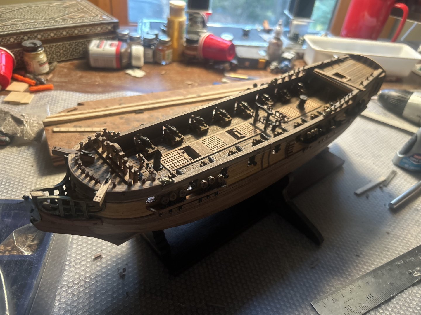
Finished at last. Every bit of wood and metal that needs to be glued to the ship is now glued. The masts are done. I will give the ship a nice coating of tung oil. Then it will be time to start the shrouds and rigging. I'll need to do a lot of research to get the rigging right. But one rope at a time...

-
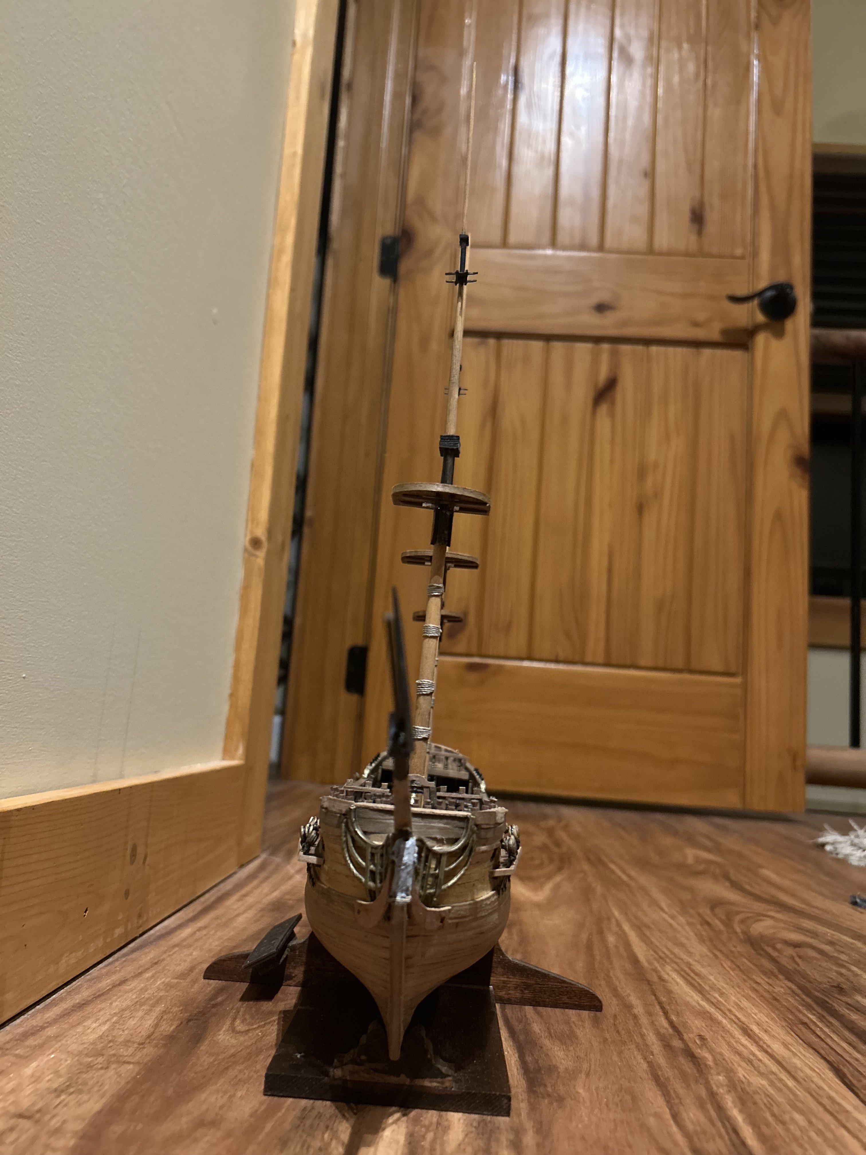
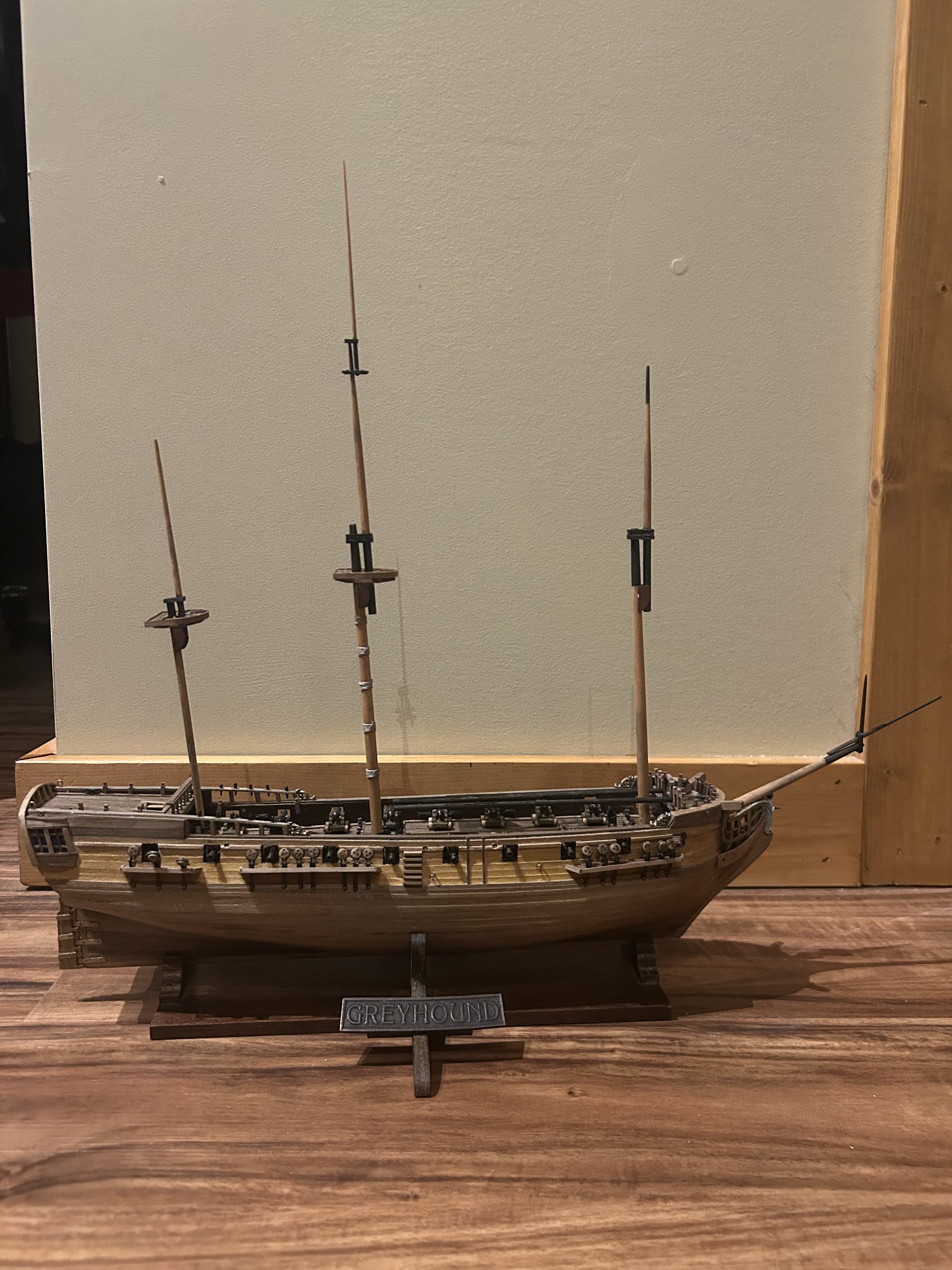
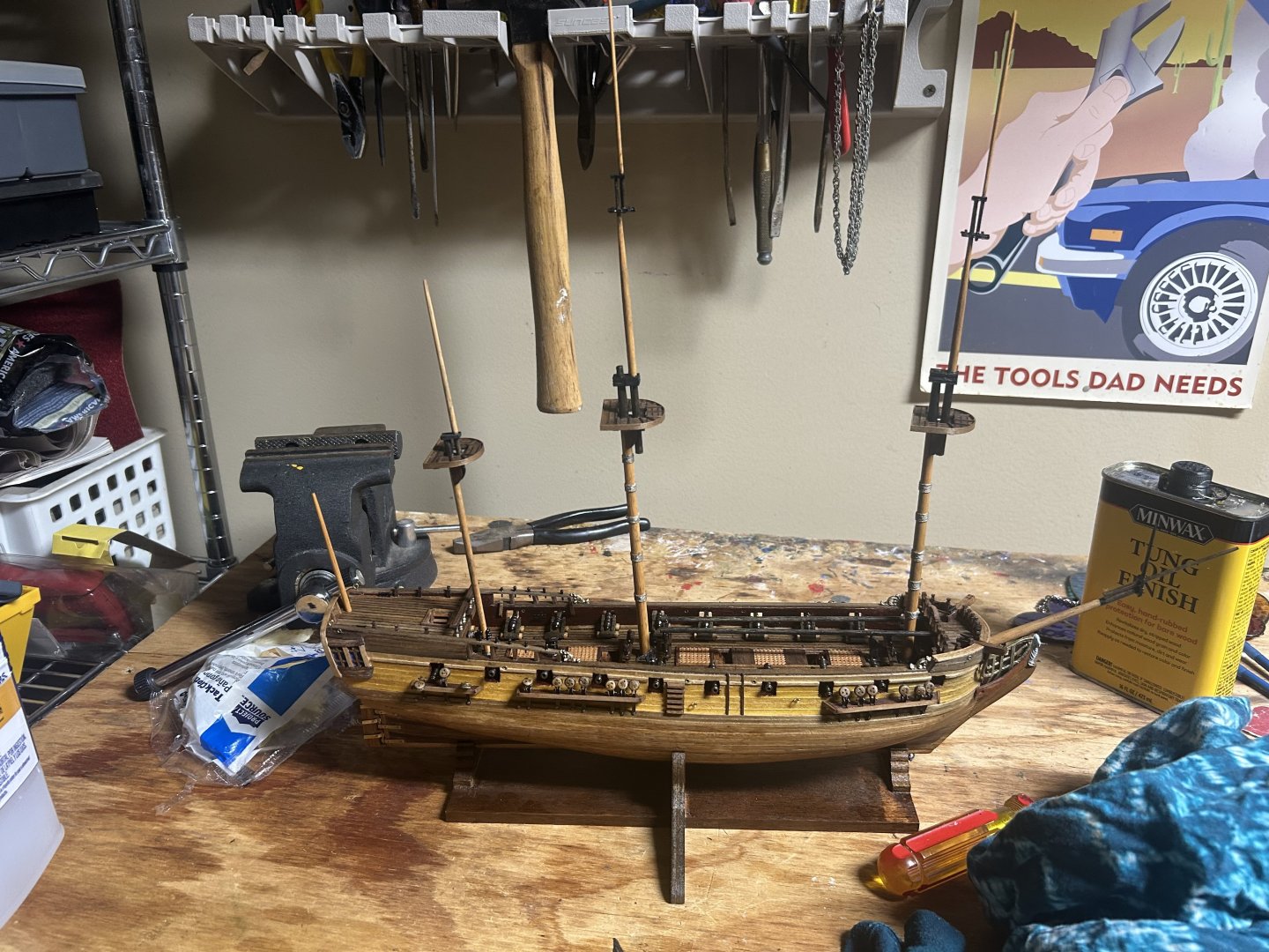
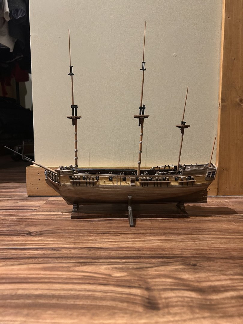
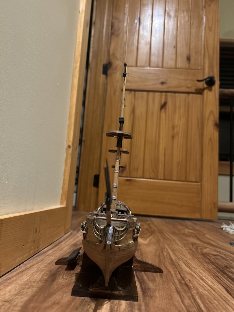
Merry Christmas and happy New Year to you all. The joys of the season have held me from my workbench. But I have made progress day by day. To cover the tops of the masts, I've been using the remainder of the deck planks, as well as 1mm by 1mm pieces. I put them on in much the same way as the deck. The final pieces that wrap around the top come from the same deck planking, and have been applied with my customary boil and bend technique. I've finished the bowsprit, the mizzen mast and the mainmast. I am now working on the foremast. I'd advise anyone working on the Greyhound to try and dry fit the tops before trying to glue them. I found the masts were slightly wider than the wood that fits around them. I had to sand the 3x2mm pieces and cut out a small curve to rest against the map. I have a picture below that shows what I mean. The end result is magnificent. It's also much taller proportionately than my intuitions would suggest. But this makes sense. There are very few ships in the world today built to carry three yards of sail on a single mast. It must have been a truly enormous task building them in real life. It must have been the project of years planning, building and outfitting a frigate.

-
Merry Christmas and Happy New Year to you all! I've decided on my next course of action. I will finish building the masts and bowsprit. Then, I'll put a layer of tung oil over all wooden parts. Then, I'll do the ropes. Everything feels easier with that plan in mind.
-
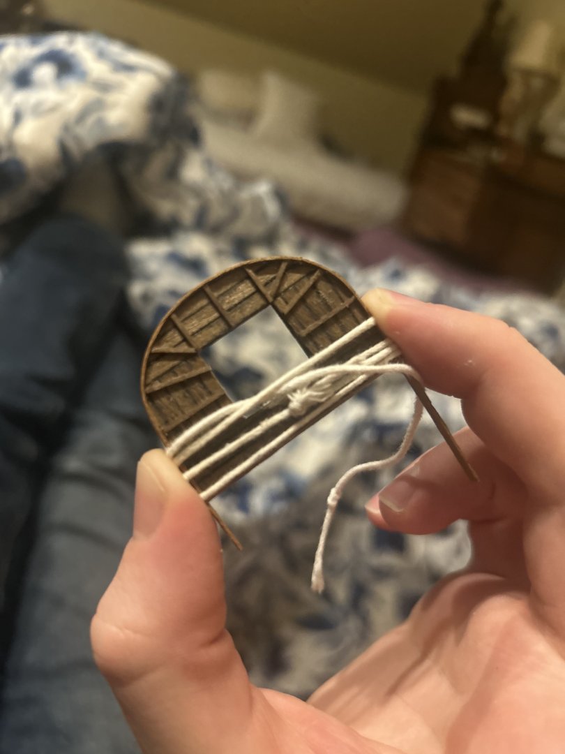
I'm back! I've been using black stain for the parts of the masts where pieces connect as well as for the spars. The rest is a pine-colored wood stain. Things have been going great. I glued in the mizzenmast and the bowsprit. The foremast and mainmast are waiting to be wrapped in twine before they're glued down. For those making the Greyhound in the future, I strongly advise that you cut or sand out the hole before you put the bowsprit decorations on. It was frightening to attempt to create a serviceable hole without breaking the stuff already in place, and I did have to use superglue to fix a couple of breaks. In just a little while, I'll be gluing on the mastheads. They're awaiting their final portion of black stain. I'd be grateful for any advice on how to attach the ratlines and other ropes. I want to do my research in advance so I can understand where and how to put these on. I'm going to look over this site for advice on what knots to use, where things attach and more before embarking on that particular adventure.


-
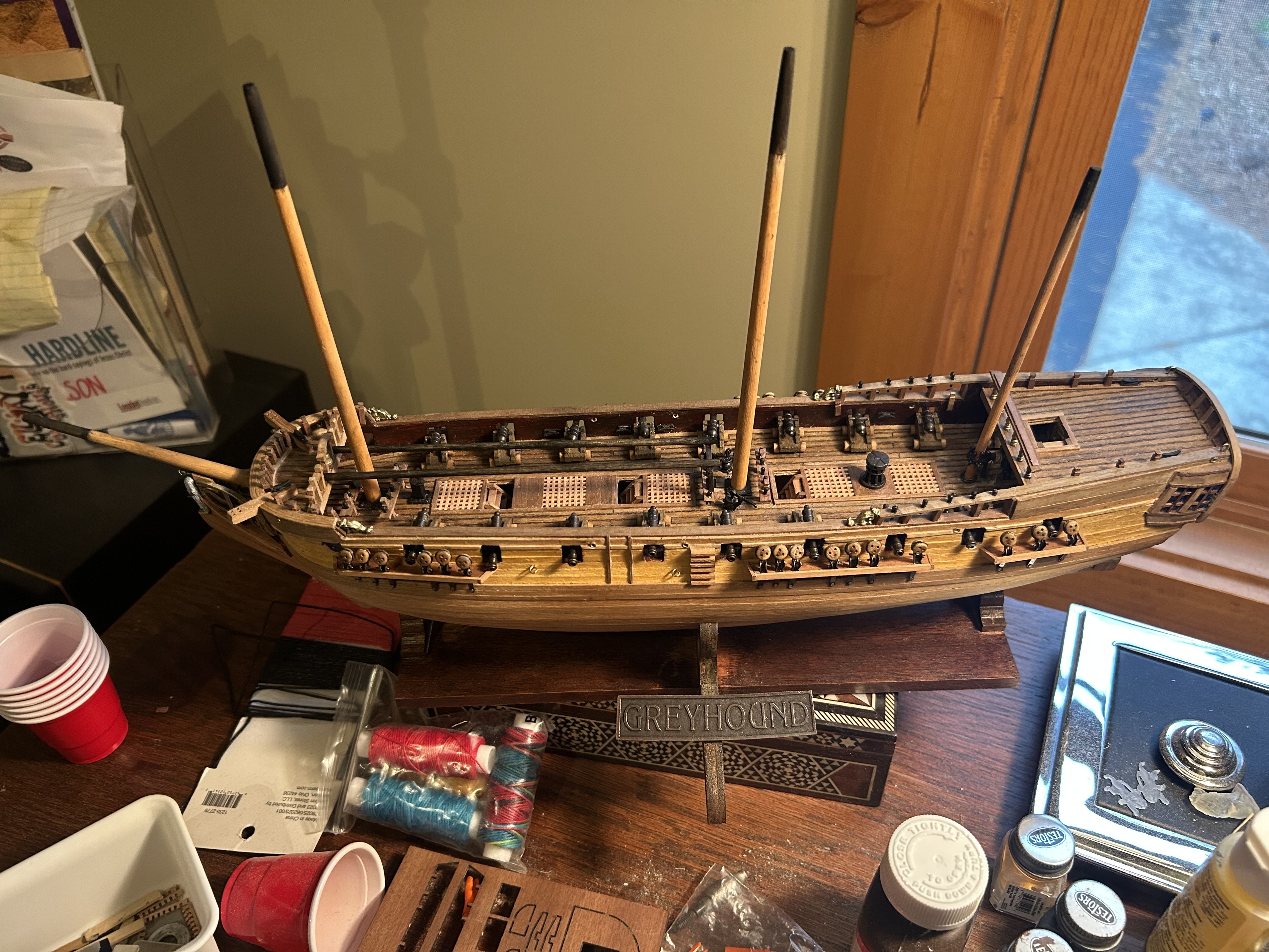
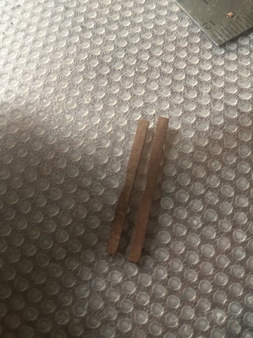
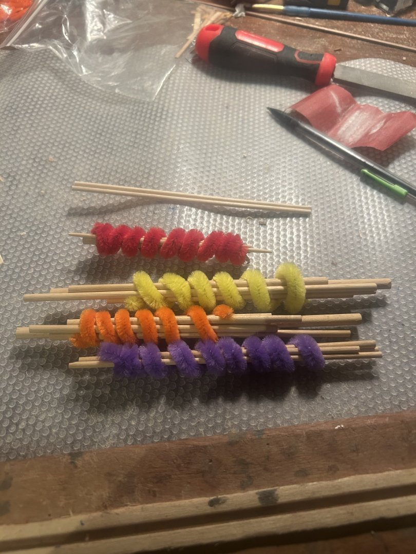
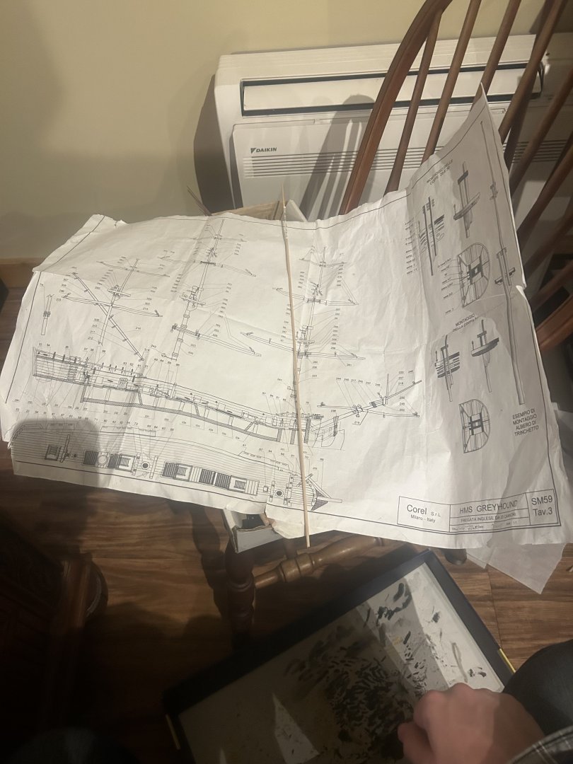
I was busier than I thought last weekend. Furthermore, I discovered the kit didn't have enough wood for the two 2.5 mm poles that hold the ship's boat. But today, I finally bought the drill bit and the wood for the poles. In the meantime, I cut the wood for the masts. For future Greyhound builders, the masts get virtually no instructions or measurements in the packet. That's why you should go to the large diagram labelled SM59 Tav. 3. This exact-sized diagram should allow you to figure out the lengths of all the pieces for this step. It looks like this: The kit also won't mention that every mast and spar is designed to taper gently from bottom to top. This tapering allows the mast pieces to actually fit together, and the yards to look prettier. So far, I've tapered everything on the bowsprit. The next step is to taper the other masts. When the sanding to shape is done, I'll use wood stain to give the masts an appropriate color. This step will take a long time and it won't provide many good pictures, so I won't be updating for a while.
-
Jackson7 reacted to a post in a topic:
HMS GREYHOUND by Jackson7 - Corel - Collaboration With My Past Self
-
Progress proceeds once more, but with a setback that will delay much further operation until Sunday. I've attached the quarterdeck rail. This step looks particularly elegant. At the same time, it's puzzling to see how two pieces of wood can be made to fit together so precisely. As usual, the answer is that these things are simpler than they appear. I made the rail by using a template made of some of my scrap wood. It was a simple matter of drilling holes in the template two mm from its edge, then putting it on top of both pieces to guide the drill. After that and a few gentle nudges, the metal pillars perfectly connected the two wood pieces. All that was left was to put a little slice of veneer scrapwood over the top to hide the holes. I was working on the six brass pieces to the side of the ship. I'm not sure what they're called because Corel's instructions don't mention them. As they are too weak to be pushed into the side like a nail, I was drilling holes for them, and my smallest drill bit broke with four more to go. I'll be buying a new one Sunday at my local hobby store.

-
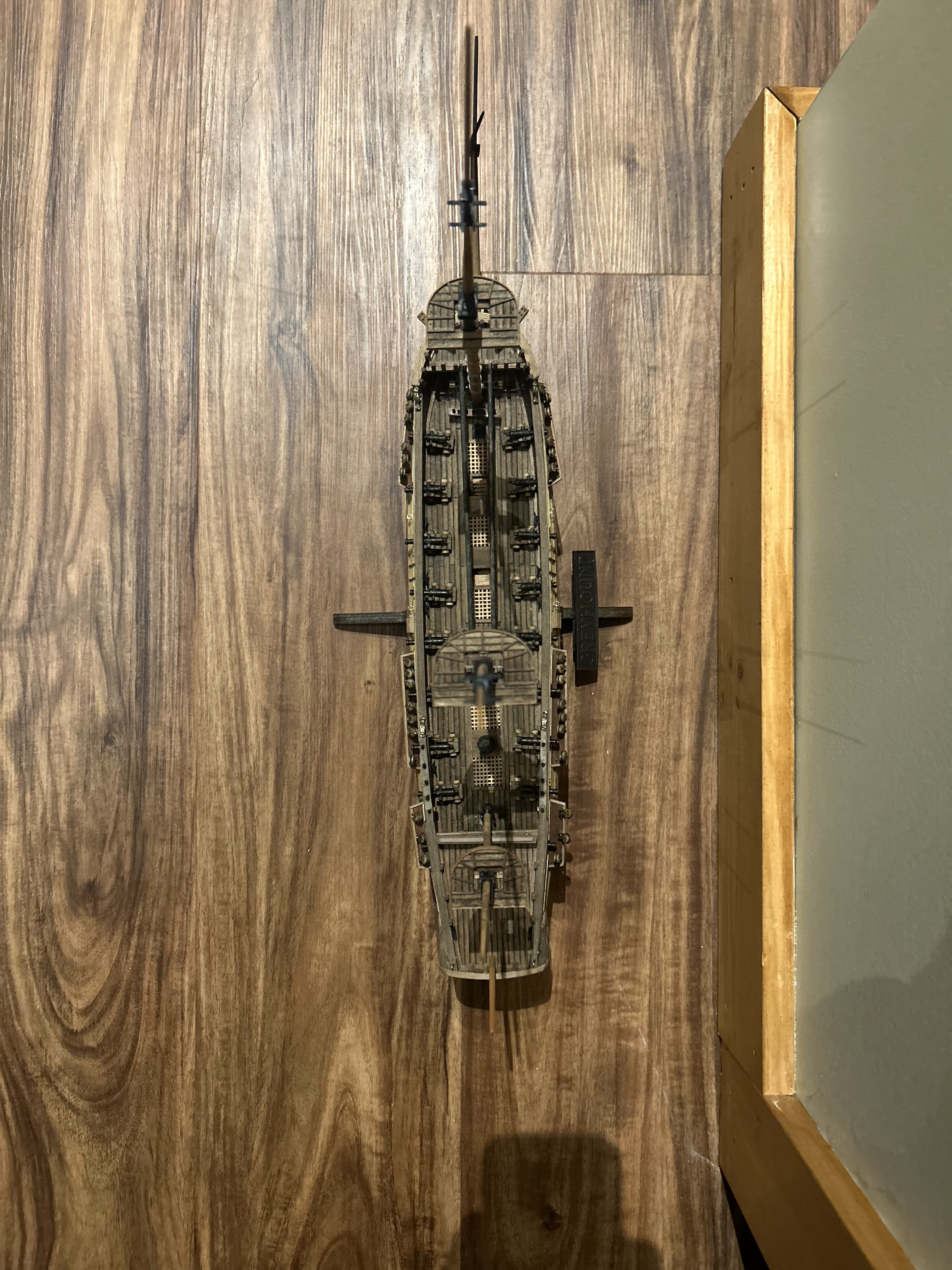
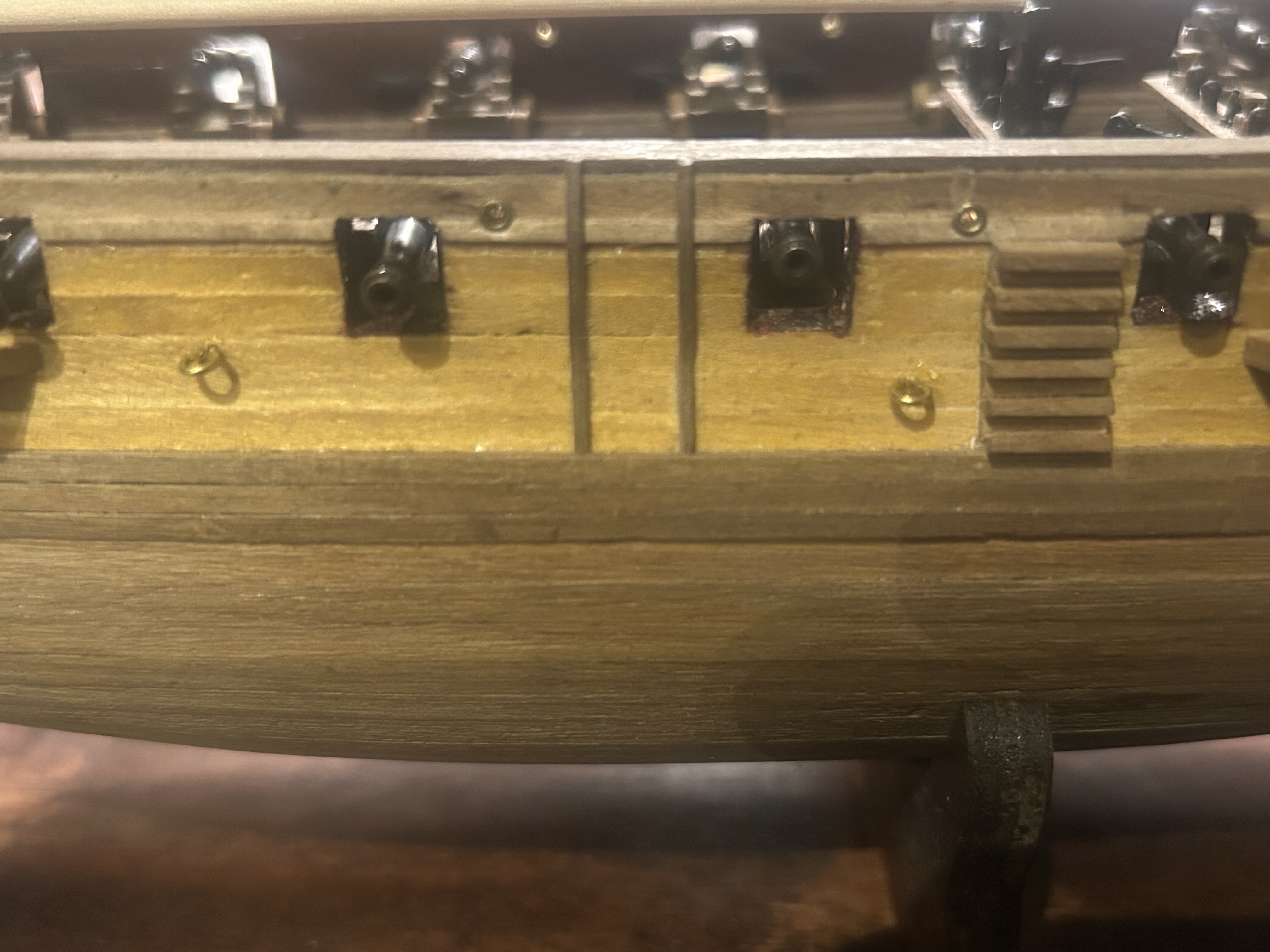
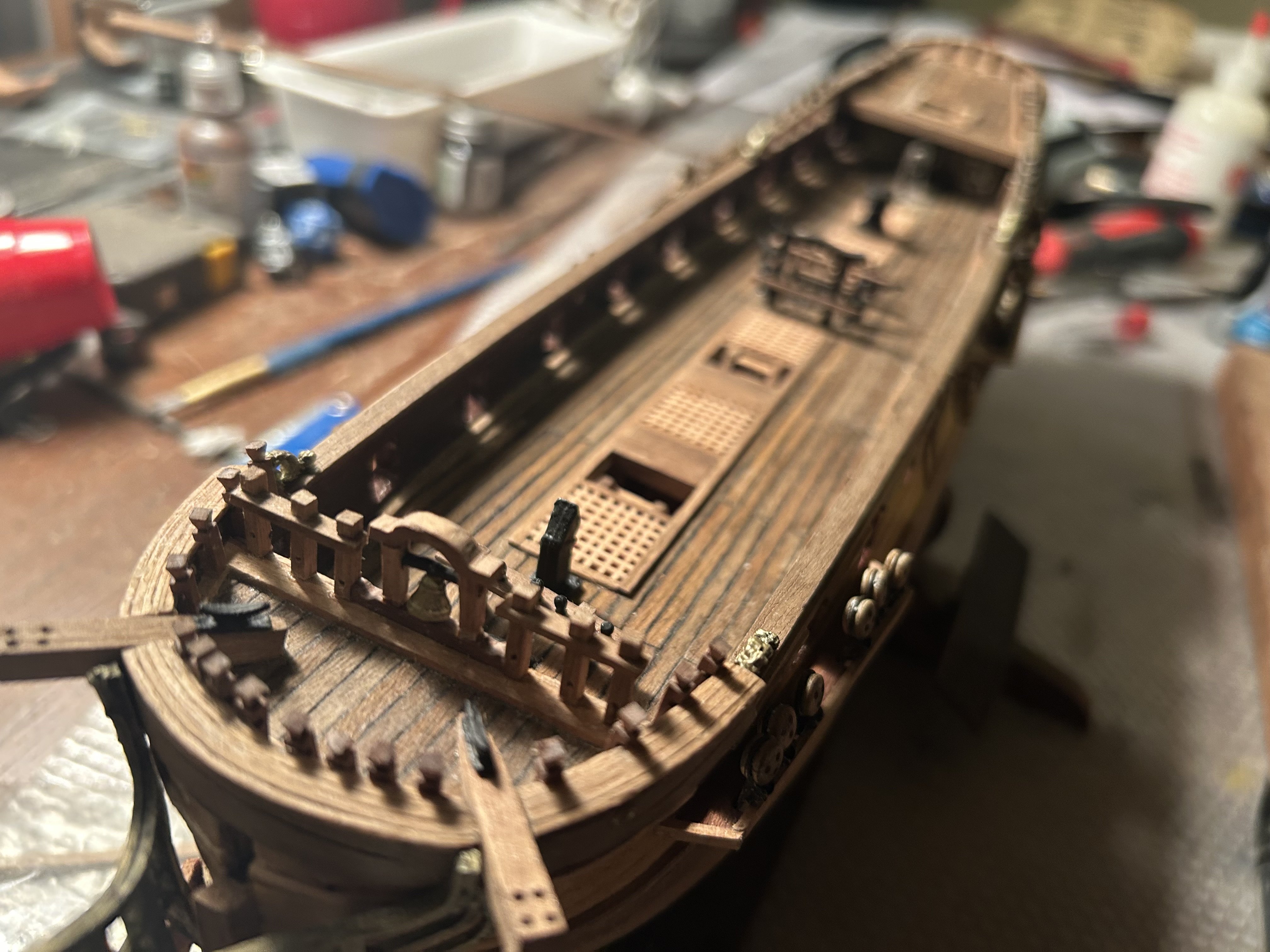
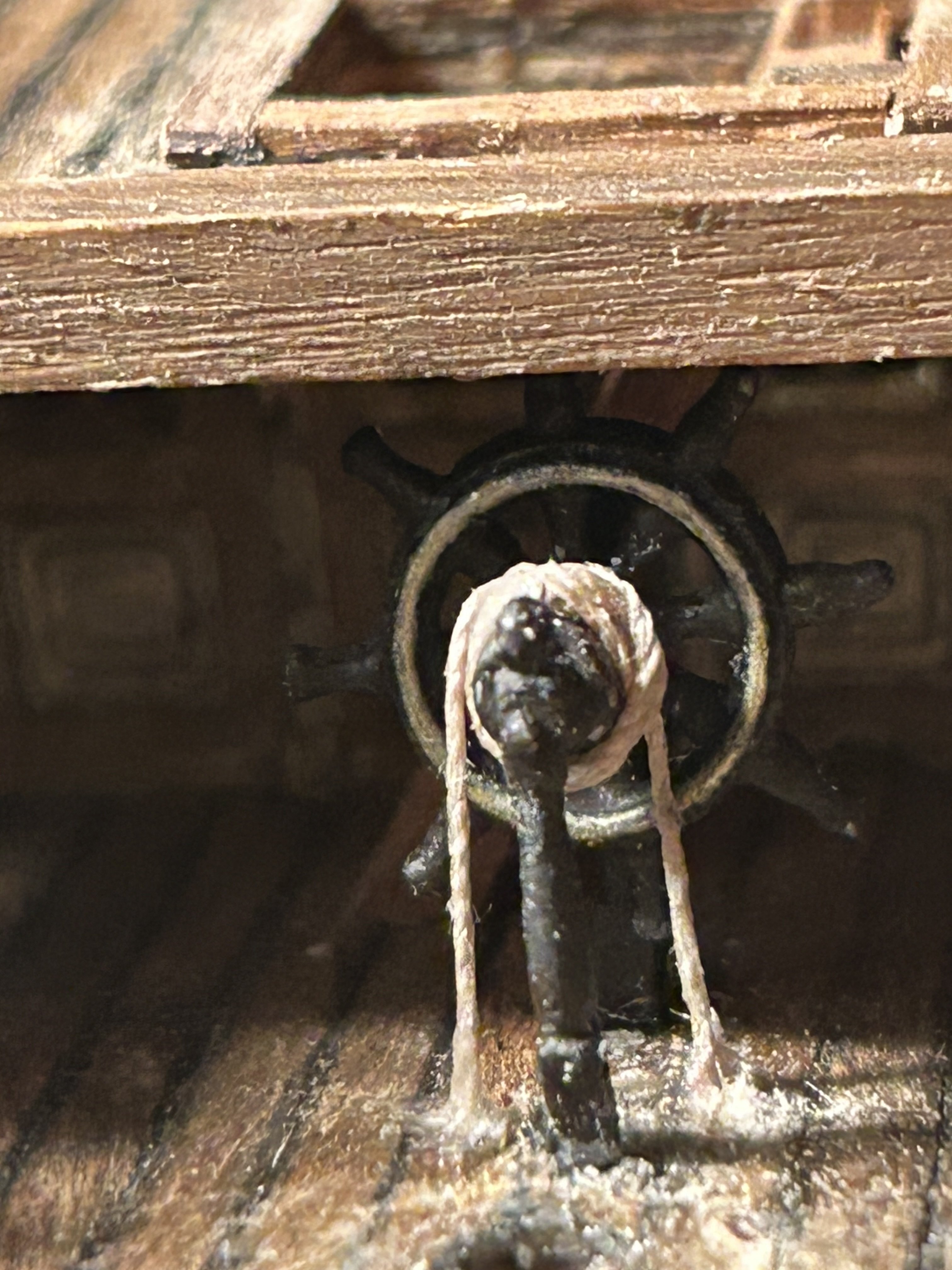
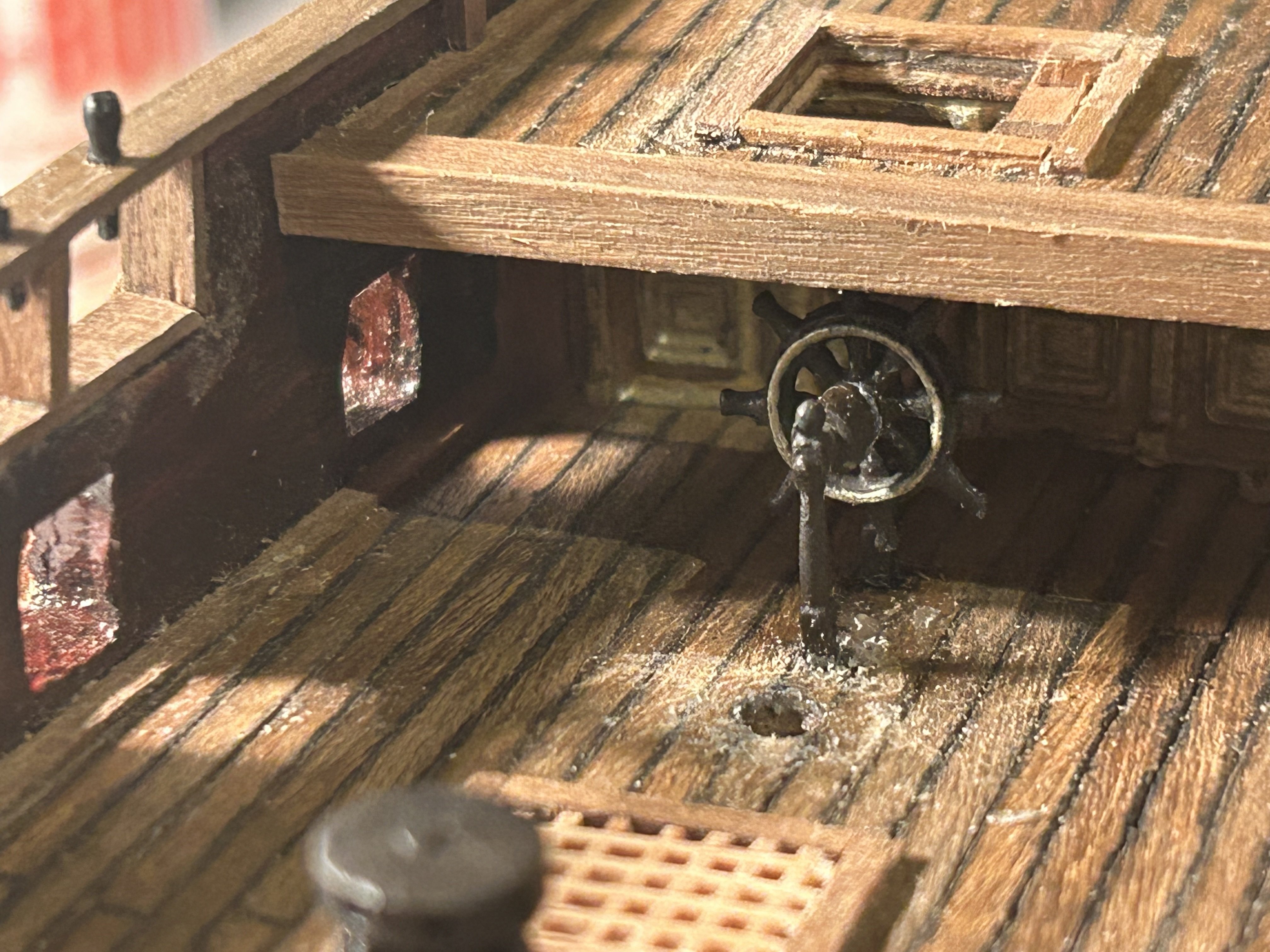
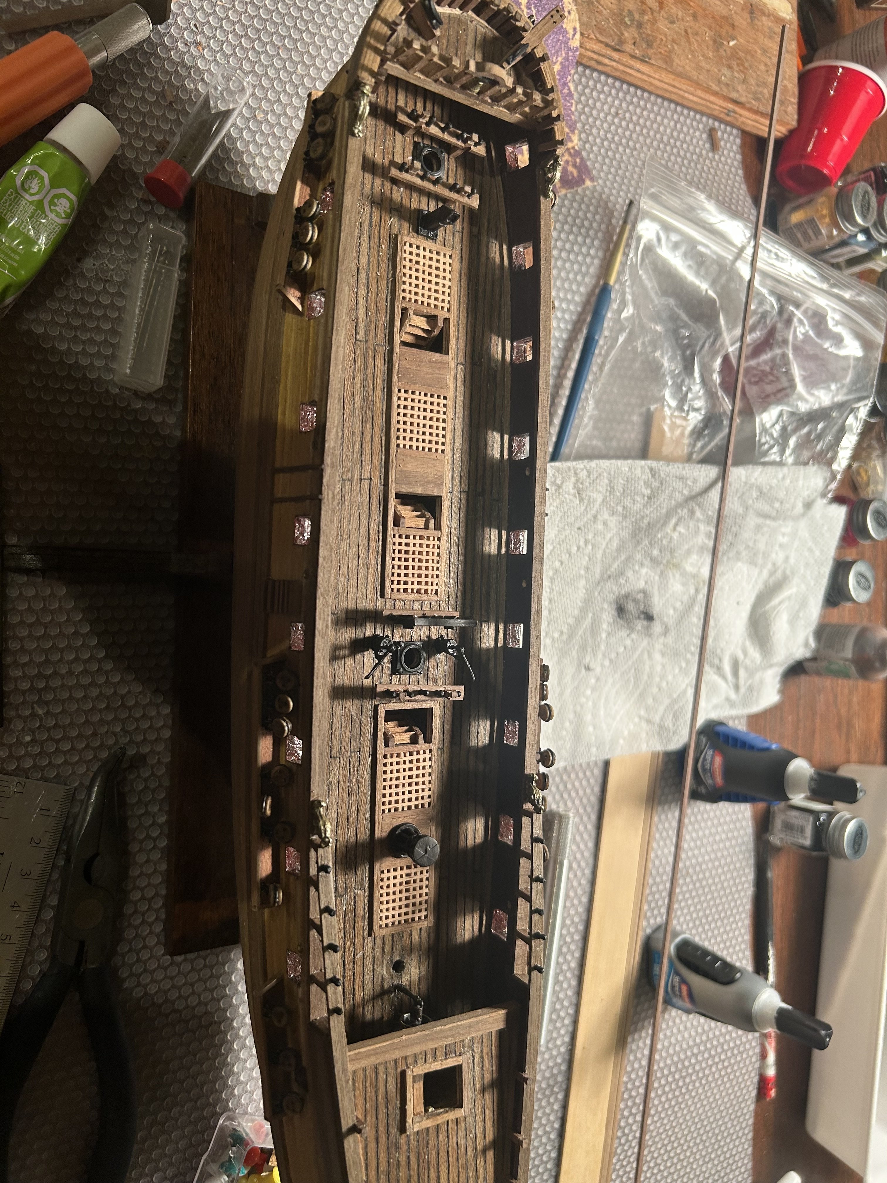
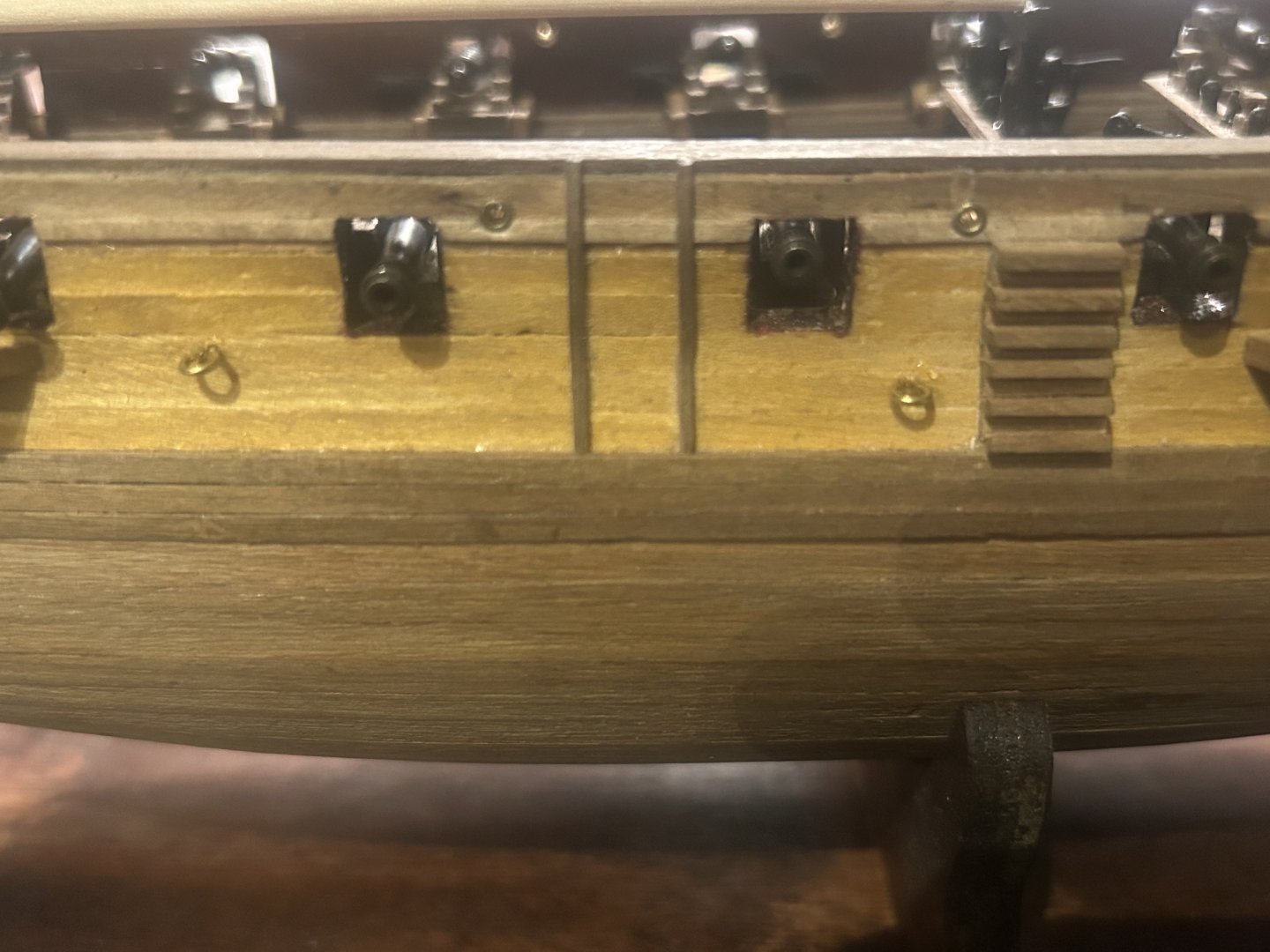
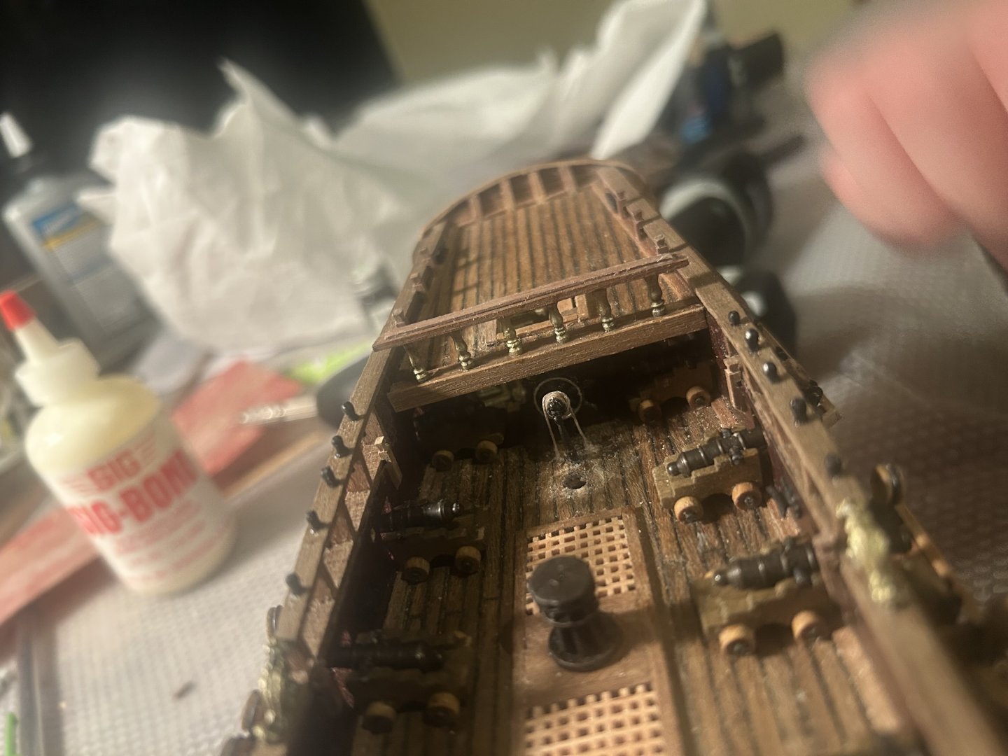
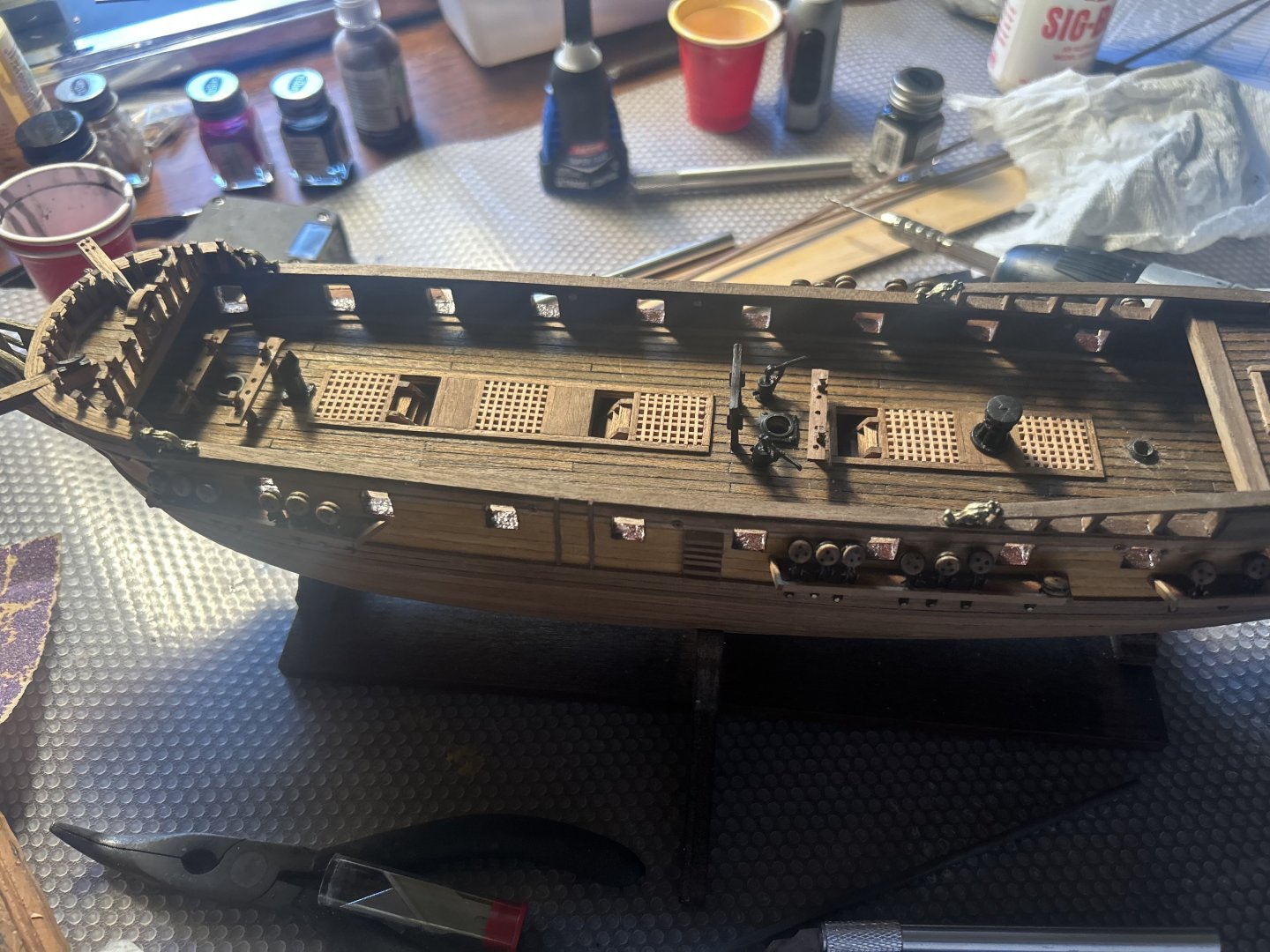
It's intriguing how many different skills building a ship involves. Putting deck furnishings on is radically different from assembling planking. Both require precision, but the precision of sanding a plank to fit bears little resemblance to placing a knighthead or drilling a hole. So far, the deck is far less trouble. At this point, I've glued on the cannons, wrapped the wheel in rope, and thanks to @harlequin's advice, I've been able to put all the cleat hitches in place. The kit's drawings require 14 cleat hitches, and the kit only provides 12. I dread to consider how I will do the masts and yards from drawings that just don't work. They are fast approaching. While gluing the cannons on, I discovered they often aren't quite even. I fixed the problem by running them over light sandpaper until the wheels were all level. It's hardly noticeable, and having four glued points of contact on the deck is a great benefit to their long-term stability. I assumed Corel's instructions were right, so my forward deck knightheads were slightly too wide to fit the foremost two guns. Don't believe the manufacturer on this model. Instead, carefully evaluate everything they show in pictures of the ship and reason out how it all ought to fit together. Measure distances yourself. The last thing to do is the rail on the quarterdeck. I've measured everything, and I'm going to start drilling holes to slot the pillars into soon. It will be finnicky to slot six different apertures together into two seperate pieces of wood, but I think I've got it. A note to other beginners: The best way to do deck furnishings is to start at the lowest area. Finish it, move higher, and don't touch the places you've already completed. Also, build the complex stuff first. You're more likely to accidentally break an easy deck fixture while working on a difficult one than to do it the other way around. I found myself wishing there had been some way to complete the main deck before putting on the quarterdeck. It was endless trouble to drill and stab holes for the ship's wheel underneath a roof.


-
Also, I found a picture of a model of the Greyhound made at the time of its actual existence. While it looks somewhat like the Corel kit, there are several big differences. For a start, the foremost aperture in the hull doesn't have a cannon in it, and it has an additional stern gunport with a cannon extremely near the cabin window. You can clearly see the oar ports above the gunwale. There aren't any roped-off walkways on deck. I'm sure you guys can spot more. https://live.staticflickr.com/65535/50950227046_c02a816bd9_b.jpg
-
I ran into a bit of trouble. The good news is I was able to put the wheel on and add in all the belaying pins. I accidentally broke off the mast base near the wheel, and it's such a bother than I plan to put it onwhile it's around the mast. I'd recommend doing this step (or at least drilling the holes for it) before putting the quarter deck on. I had to use a thumb tack to press holes in the hull where a drill couldn't reach. The bad news is that I kinda damaged my work on the top deck trying to put in railings. And then I discovered that there's no way they are comfortably at 1/100 scale. I've calculated that they would be nearly 5 feet high. Rope railings at neck level are uncomfortable at best. At worst, they're a way to combine strangulation with falling down the stairs. Given that I doubt my ability to drill holes to contain them and that they are too big, I'm just going to eschew railings. Safety regulations were probably not high on the priority list in 1720 anyway.


-
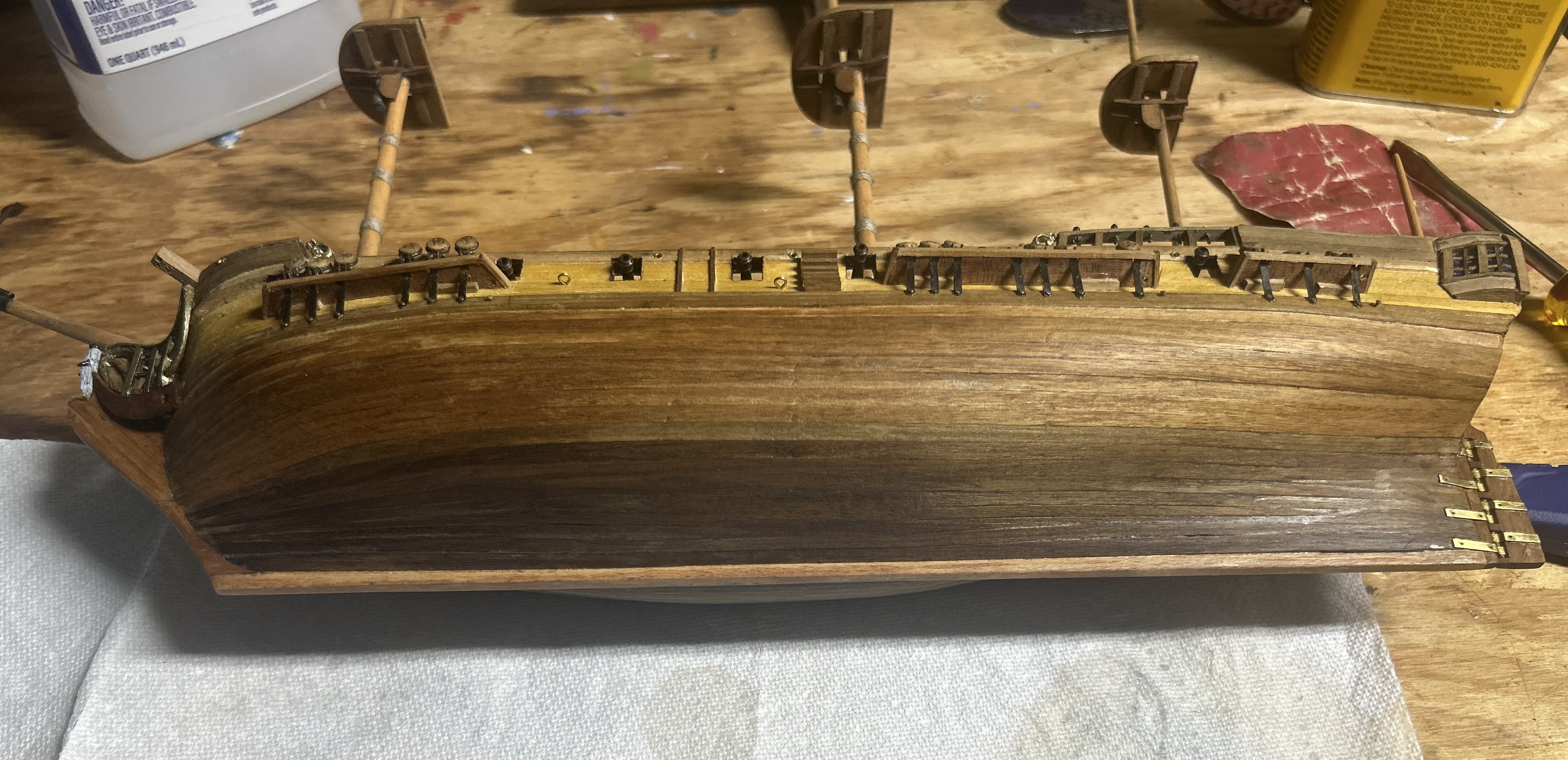
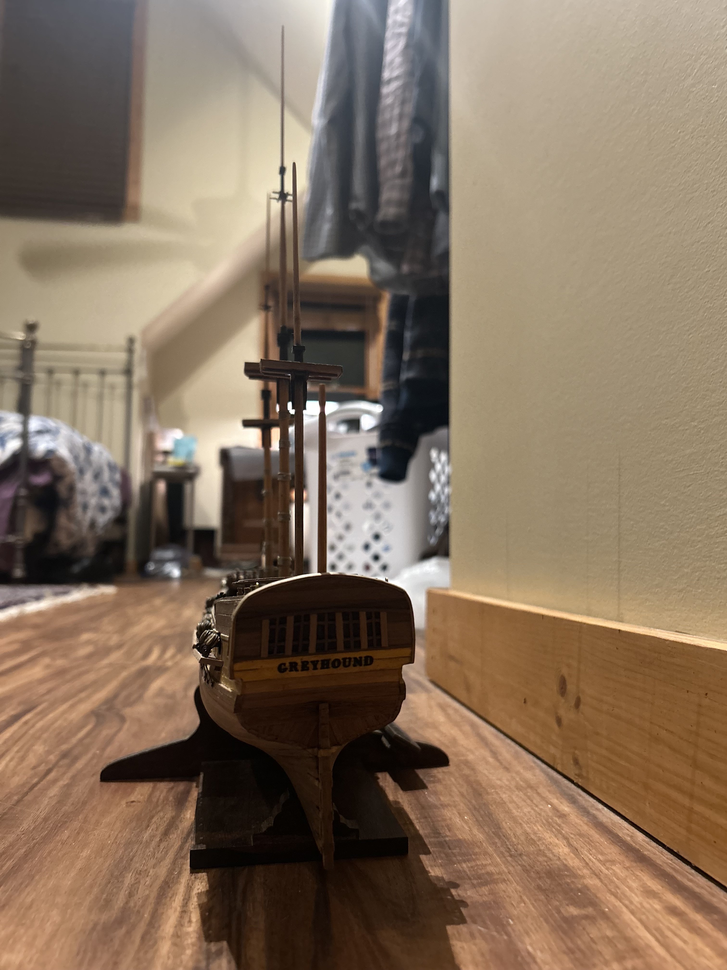
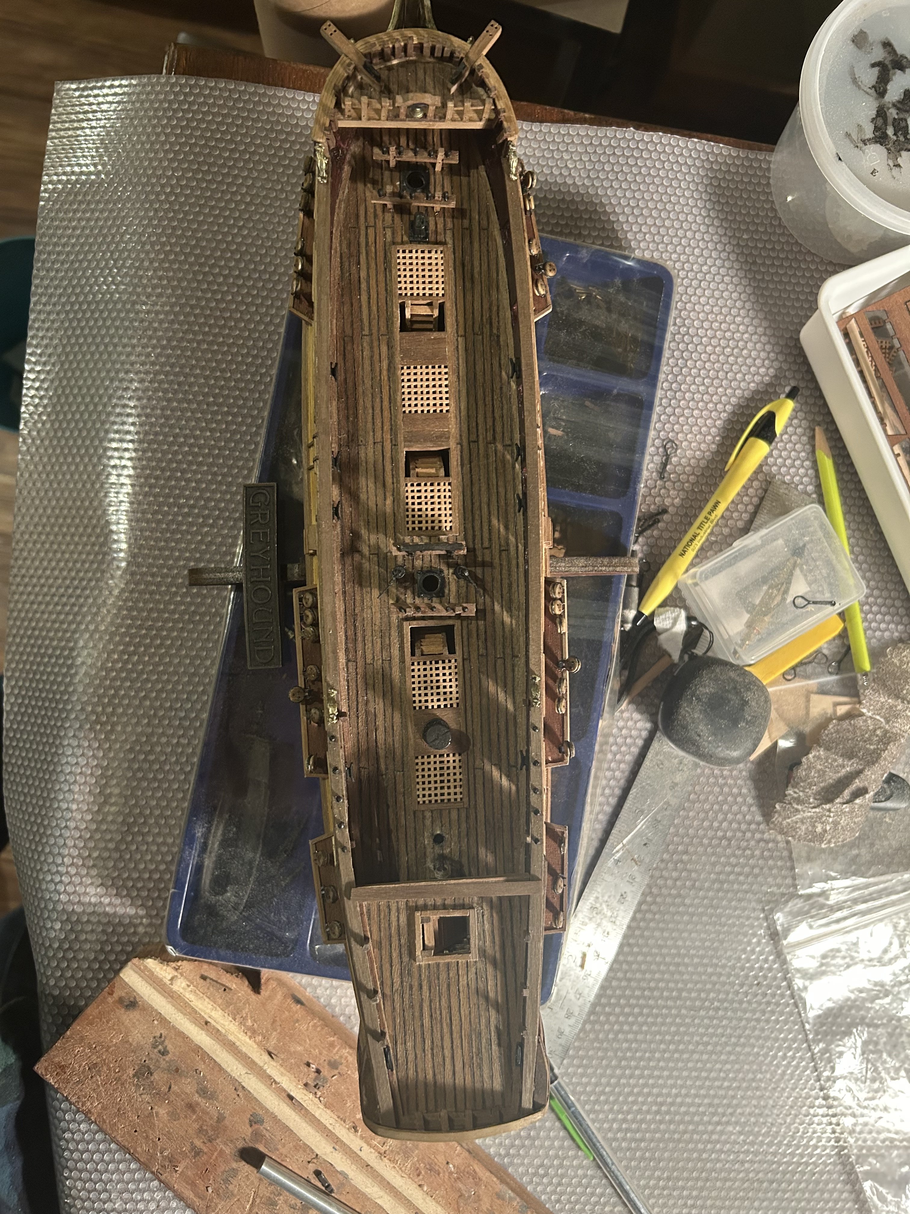
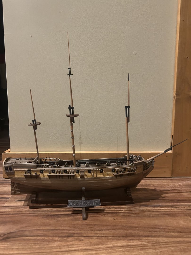
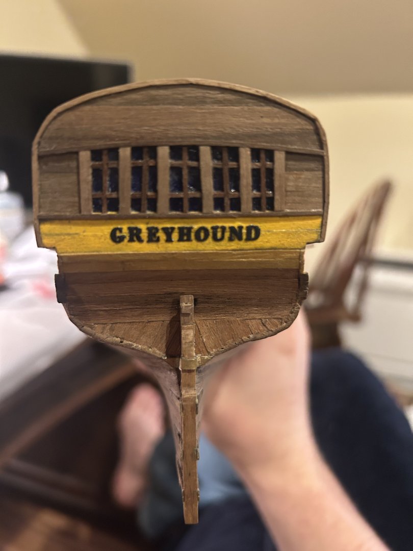
Sometimes it's the little things that make a ship come together. I bought some 3 mm high letters from Walmart to put the name on the stern. After some cleaning, sanding and painting, they were ready to place on. They give the stern that last little spark of color it needs to work. I've discovered that the bow might be too crowded to fit the front two guns. I might be able to work around it, but it's likely I'm making an 18-gun ship. No big deal though.
-
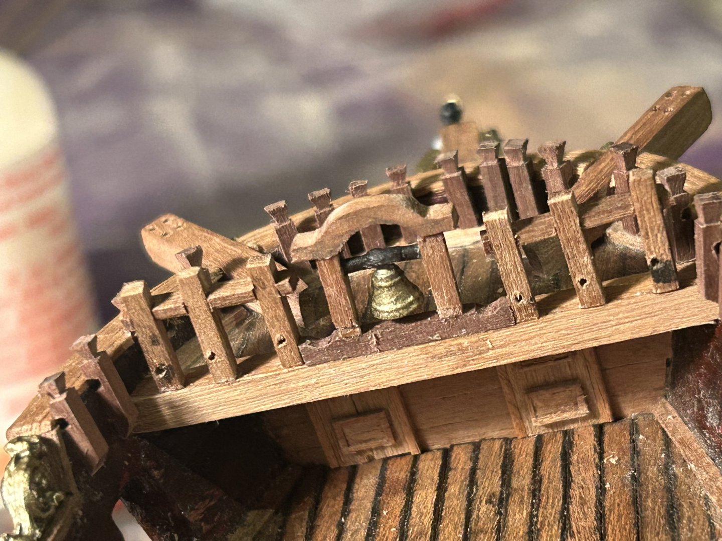
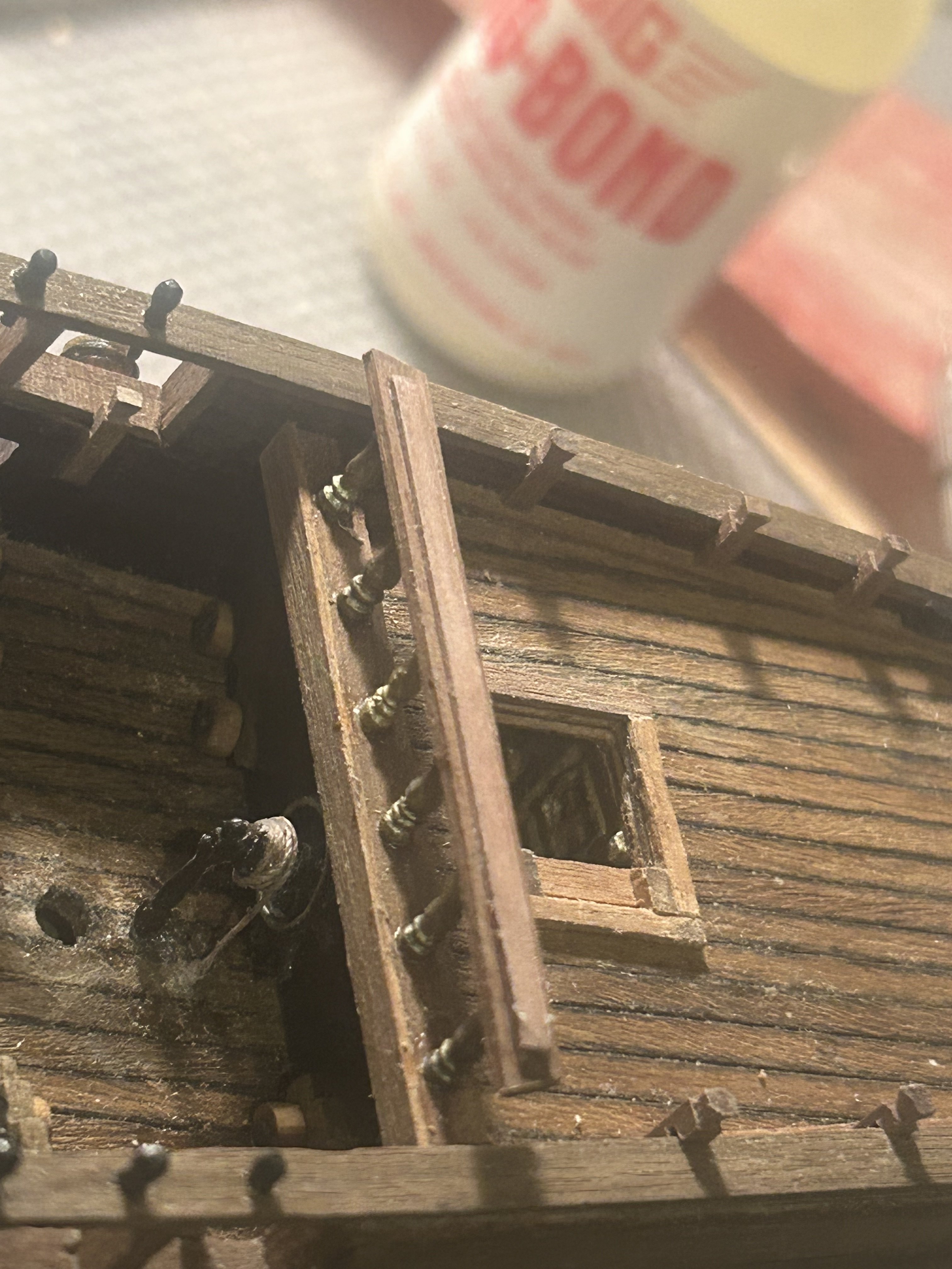
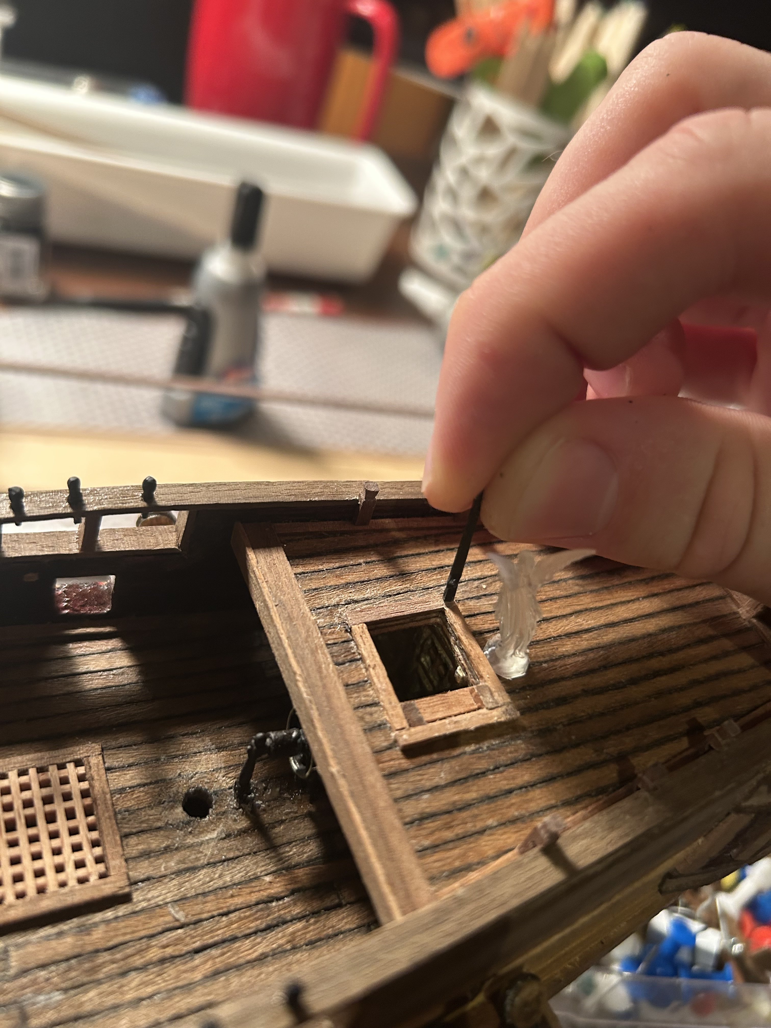
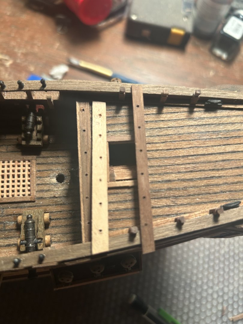
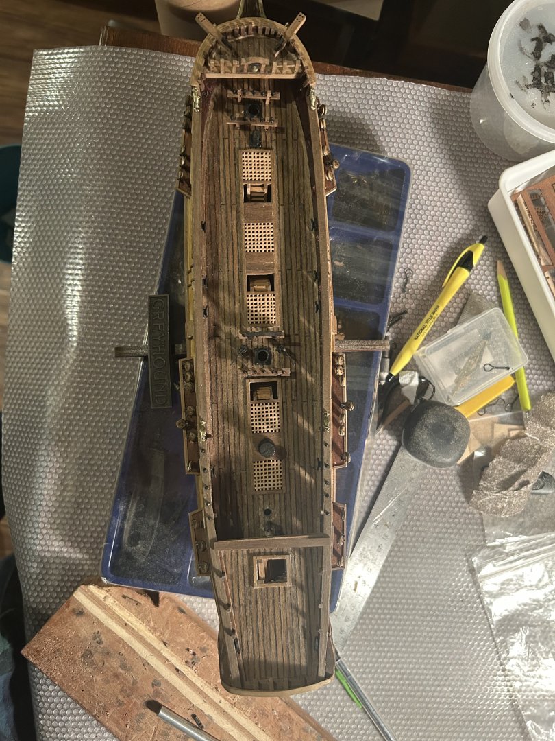
Why work from a kit when you can take four times as long doing it yourself? Slowly, carefully, I have carved wooden deck pieces for every parrt I've felt capable of carving. It's worked great. They look way better. Putting into the deck was frightening. I drilled hoes in the deck where they attached, then carved the ends of the square pegs into circular shapes. They went into the holes fairly easily. It was much better than trying to carve square holes to put them into. Now, I have just the back rail and the little railings for the stairs.
-
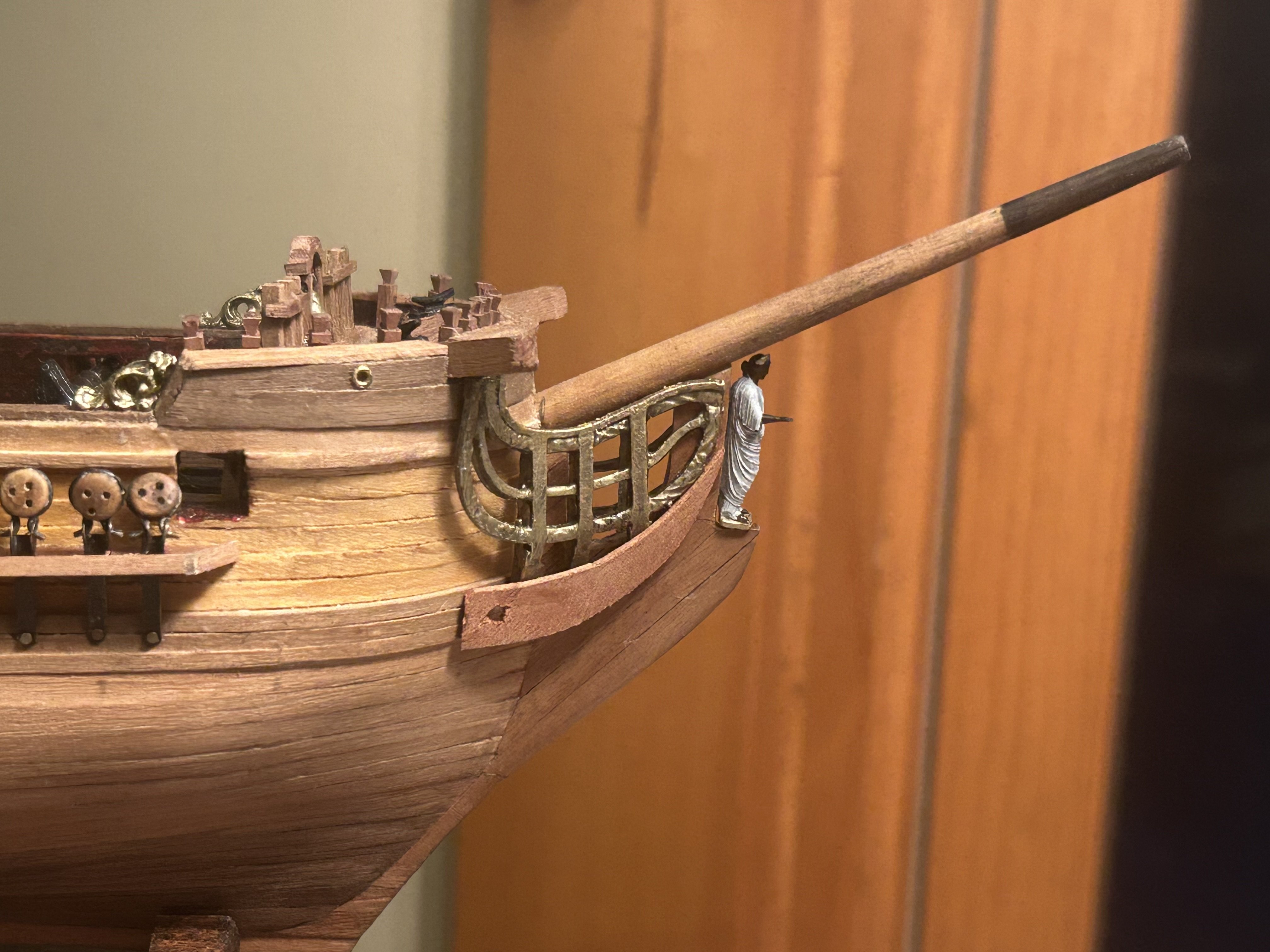
When the metal bannister provided by the kit didn't fit, I built my own. It may be the best bit of carving I've done yet on this insane project. It looks far more natural than the original. Now, I just have the other railing and all the wood knighthead things in the center. We'll see just how they go.