


Tecko
-
Posts
336 -
Joined
-
Last visited
Recent Profile Visitors


-
 Very nice work. Looking forward to seeing the rest of the build, if that is possible. Hoping the new year 2026 will bring you much joy in your creativity.
 -
 Tecko reacted to a post in a topic:
HMS Endurance by GiddyGibberish - OcCre - 1:70
Tecko reacted to a post in a topic:
HMS Endurance by GiddyGibberish - OcCre - 1:70
-
Tecko reacted to a post in a topic:
HMS Endurance by GiddyGibberish - OcCre - 1:70
-
Tecko reacted to a post in a topic:
HMS Endurance by GiddyGibberish - OcCre - 1:70
-
Tecko reacted to a post in a topic:
HMS Endurance by GiddyGibberish - OcCre - 1:70
-
Tecko reacted to a post in a topic:
HMS Endurance by GiddyGibberish - OcCre - 1:70
-
Tecko reacted to a post in a topic:
HMS Endurance by GiddyGibberish - OcCre - 1:70
-
Tecko reacted to a post in a topic:
HMS Beagle by usedtosail - OcCre - 1:60
-
Tecko reacted to a post in a topic:
HMS Beagle by usedtosail - OcCre - 1:60
-
Tecko reacted to a post in a topic:
HMS Beagle by usedtosail - OcCre - 1:60
-
JerryTodd reacted to a post in a topic:
Copper plate overlapping (< > 1794) - lower overlaps upper or vice versa?
-
Keith Black reacted to a post in a topic:
Newbie wannabe!
-
Tecko reacted to a post in a topic:
Newbie wannabe!
-
Admiral Rick reacted to a post in a topic:
Newbie wannabe!
-
Paul White reacted to a post in a topic:
Newbie wannabe!
-
Welcome @Paul White. I am a beginner myself. However, I do have a few transferable skills, like everybody else, which make this hobby quite manageable. Those transferable skills play a significant role in terms of the required tools to do the job. You may find that you do not need many tools at all. In my opinion, the main transferable skill is self-confidence. With it, any obstacle can be overcome. Anyone who thinks they would like to give this hobby a go already has the needed self-confidence to master it. So settle in, and have fun mastering what you already know you can master.
-
DonSangria reacted to a post in a topic:
HMS Beagle by Tecko - OcCre - 1:60
-
vvvjames reacted to a post in a topic:
HMS Beagle by Tecko - OcCre - 1:60
-
vvvjames reacted to a post in a topic:
HMS Beagle by Tecko - OcCre - 1:60
-
The Gimps Chimp reacted to a post in a topic:
HMS Beagle by Tecko - OcCre - 1:60
-
The Gimps Chimp reacted to a post in a topic:
HMS Beagle by Tecko - OcCre - 1:60
-
The Gimps Chimp reacted to a post in a topic:
HMS Beagle by Tecko - OcCre - 1:60
-
HMS Beagle by Tecko - OcCre - 1:60
Tecko replied to Tecko's topic in - Kit build logs for subjects built from 1801 - 1850
The upper deck has not yet been attached. The 3mm LED is not ON; it's just the external light diffusing through the clear LED housing. This LED is actually a red LED for night vision.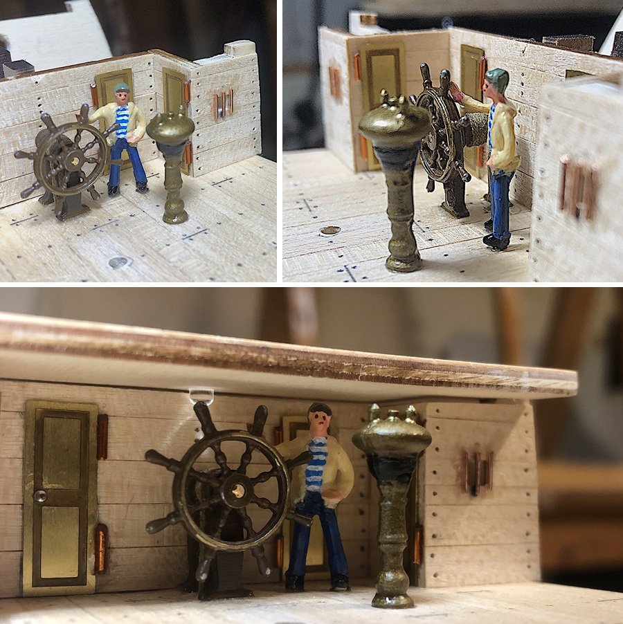
-
HMS Beagle by Tecko - OcCre - 1:60
Tecko replied to Tecko's topic in - Kit build logs for subjects built from 1801 - 1850
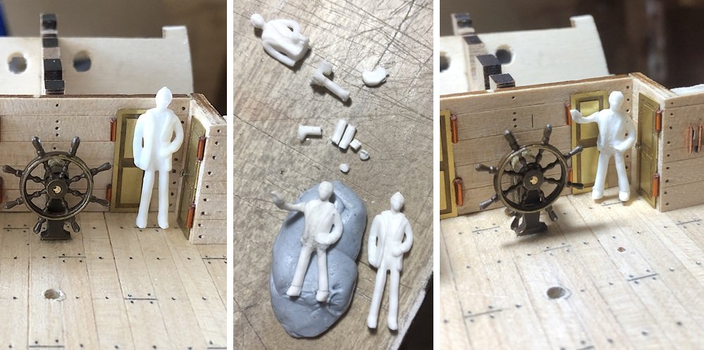
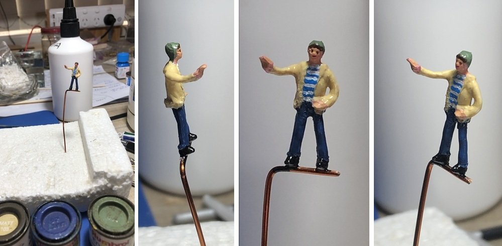
The helm's wheel was attached to the deck. The steering rope was fed through the deck and glued to the framework to show tension in the rope. I was not too happy about the cutdown version of the helmsman, so I operated on him again. This time, instead of just cutting his legs, I cut a piece out of his midsection and some of his lower legs. This made him more proportional in appearance. I found that Blu Tack works well to keep loose parts in place while gluing with Supa glue. Then I stuck the figure on some copper wire, as a stand, to paint it.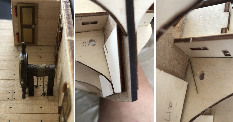
-
HMS Beagle by Tecko - OcCre - 1:60
Tecko replied to Tecko's topic in - Kit build logs for subjects built from 1801 - 1850
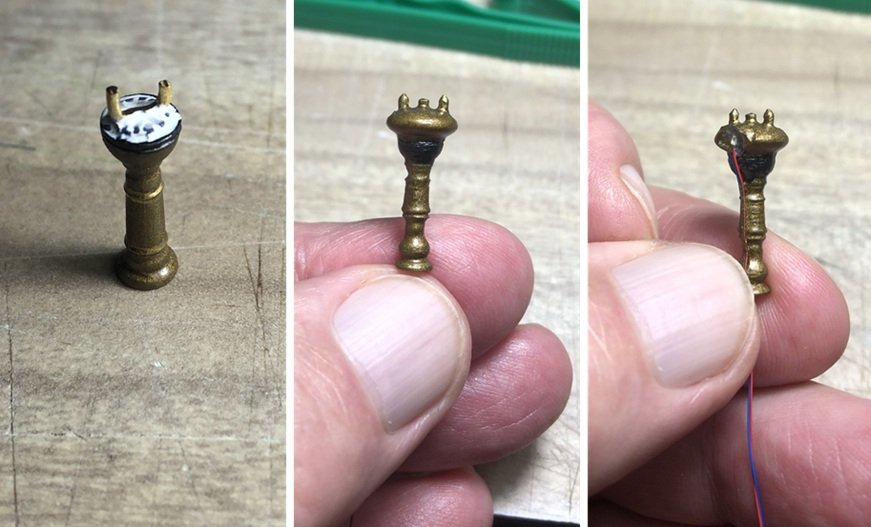
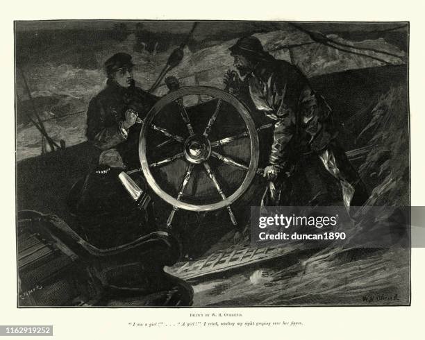
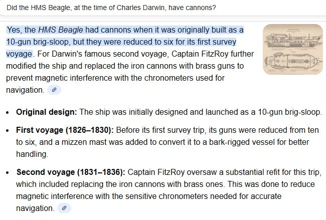
Throughout the festive season, I fell (caught two bouts of cold in the middle of summer!). Being 70+ y.o. is vastly different from being 60+. Anyway, I did get to do a bit here and there towards the build. I hesitated attaching the upper aft deck due to needing to put the helm section underneath it, as well as a night (red) light. I decided it was best to put those bits in first. Since the sailors of the period were short in stature, even 1:72 scale figures were too tall for a 1:60 scale ship. I had to cut the poor helmsman down to size. I also amputated his arm to relocate it to handle the helm's wheel. I think the helsman will look better after I paint him. At first, I really botched up both the Marine and Binnacle compasses. They are bloody small! And my peepers are not exactly on the ball. I tried to drill out the Binnacle compass window, but that did not work out too well. However, to some degree, I was able to recess the red micro LED into it. My goal is to have some sort of light reflection onto the helmsman. Something like in the following image...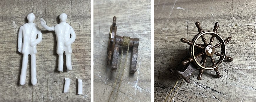
-
HMS Beagle by Tecko - OcCre - 1:60
Tecko replied to Tecko's topic in - Kit build logs for subjects built from 1801 - 1850
If it is accurate, then the cannon balls need to be brass as well. 😉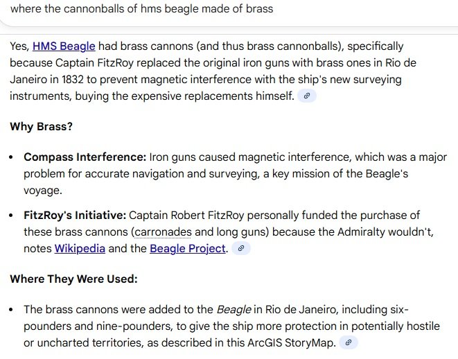
-
HMS Beagle by Tecko - OcCre - 1:60
Tecko replied to Tecko's topic in - Kit build logs for subjects built from 1801 - 1850
Hi Brant. Thanks for the compliment. Yes, I am still making a display case, but a different base design since I am no longer making a diorama. I have never made a display case before, and I am not a carpenter either, but I have confidence that it will turn out okay. My main concern is the weight of it all if I am using 3mm glass sheets. I don't like plexiglass/Perspex. Additionally, at this moment, I am unsure exactly how I will terminate the wiring. I am going to use ordinary PVC electrical tubing as hollow stands between the hull and the display base. The wires will be channeled through them. Because I plan to have some control over the lighting (switching and dimming), there will be a lot of wires exiting through the stands. Once the wiring harness is sorted, I can then start planking the hull, which I am looking forward to having a go at. -
HMS Beagle by Tecko - OcCre - 1:60
Tecko replied to Tecko's topic in - Kit build logs for subjects built from 1801 - 1850
-
HMS Beagle by Tecko - OcCre - 1:60
Tecko replied to Tecko's topic in - Kit build logs for subjects built from 1801 - 1850
While waiting for the glue to dry on the planking of the fore and aft upper decks, I painted the cannons with metallic brass paint. The cannons, even after two coats, have a tarnished look about them, which I like. In case you were wondering why I chose to brass the cannons...
-
HMS Beagle by Tecko - OcCre - 1:60
Tecko replied to Tecko's topic in - Kit build logs for subjects built from 1801 - 1850
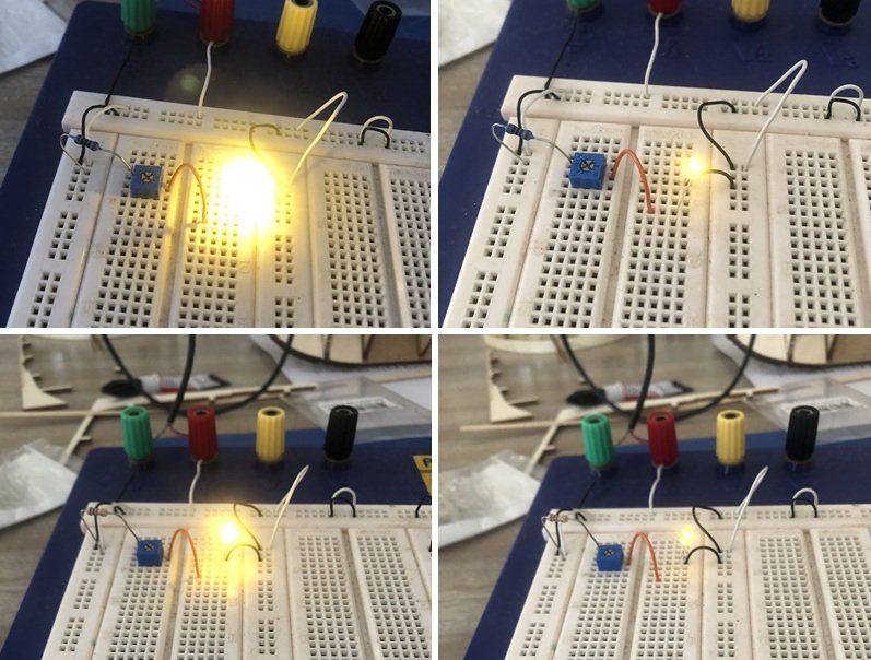
I tested both the red and warm white-colored micro LEDs and chose a different value for R (see above, post #101). The value for RV is 10k ohms. Here, R = 150 ohms. It's the right degree of maximum brightness from my point of view. Red LED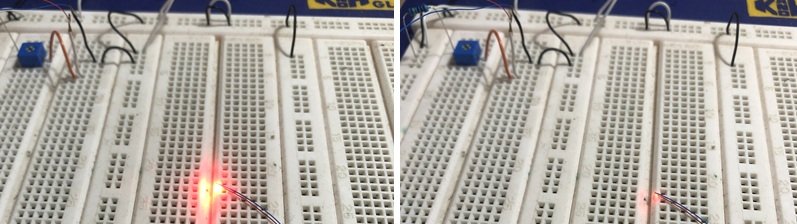
-
HMS Beagle by Tecko - OcCre - 1:60
Tecko replied to Tecko's topic in - Kit build logs for subjects built from 1801 - 1850
No, not at all. The LED only draws 0.02 amperes, at the most, at 3V. When the LED is brightest. V x I = Watts. 3V x 0.02A = 0.06W The resistor is rated at 0.5W -
HMS Beagle by Tecko - OcCre - 1:60
Tecko replied to Tecko's topic in - Kit build logs for subjects built from 1801 - 1850
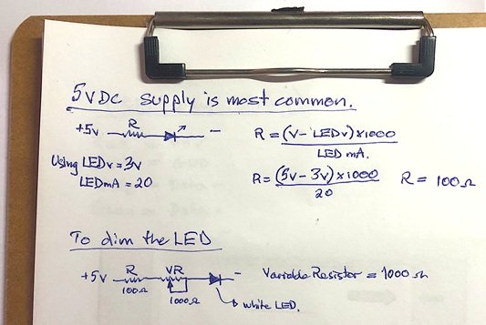
To light my model, I decided to use LEDs and a common DC voltage source (5Volts) from a USB charging socket. I stripped a USB cable to find and check which coloured wire carried the 5V. It's the red wire. The LEDs I am using have a 3V drop and use 20 milliamps (mA). The following formula calculates the load resistor value to use to drop the 5v to the required 3V at 20mA. It turns out to be 100 ohms. To dim the LED I decided to use a variable resistor up to 10x the load resistor (i.e., 1k ohms), which worked well in my past 'aged' projects. To my surprise, I discovered that LEDs are much brighter these days! I needed to increase the resistor values by 10 times to get a reasonable dimming effect. Now the R=1k ohms and VR=10k ohms.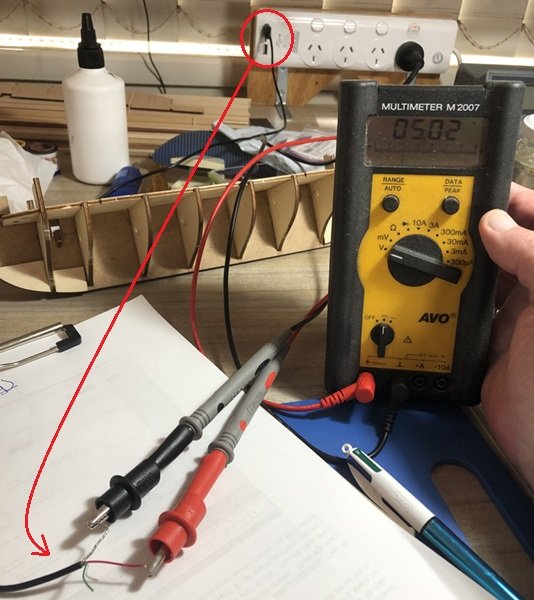
-
@theoracle09 What an awesome build. I forgot to put 'likes' throughout your thread. Sorry. I got all caught up looking and learning from this build. I am currently building the HMS Beagle, and your build of the Endurance has inspired me to finish my current build and possibly, for my second build, do the Endurance. Thank you, and all other contributors, for sharing.
-
HMS Beagle by Tecko - OcCre - 1:60
Tecko replied to Tecko's topic in - Kit build logs for subjects built from 1801 - 1850
The weather here in Australia has been too hot for me to work on my model without sweating all over it. From the beginning of this build, I had a few alternative ideas I wanted to implement. One was to remake the stern quarter galley windows to have windows. But I discovered that in reality, the galley windows were fake, built simply as an ornament. To model them to have windows would have been a bigger fake. I learnt that quite often, while looking at windows, what one sees is a greyish background. So I decided to apply a few coats of clear ultra-gloss varnish to the windows. This produced a glare effect. The photo below shows the glare as white (it's the best my iPhone can reproduce).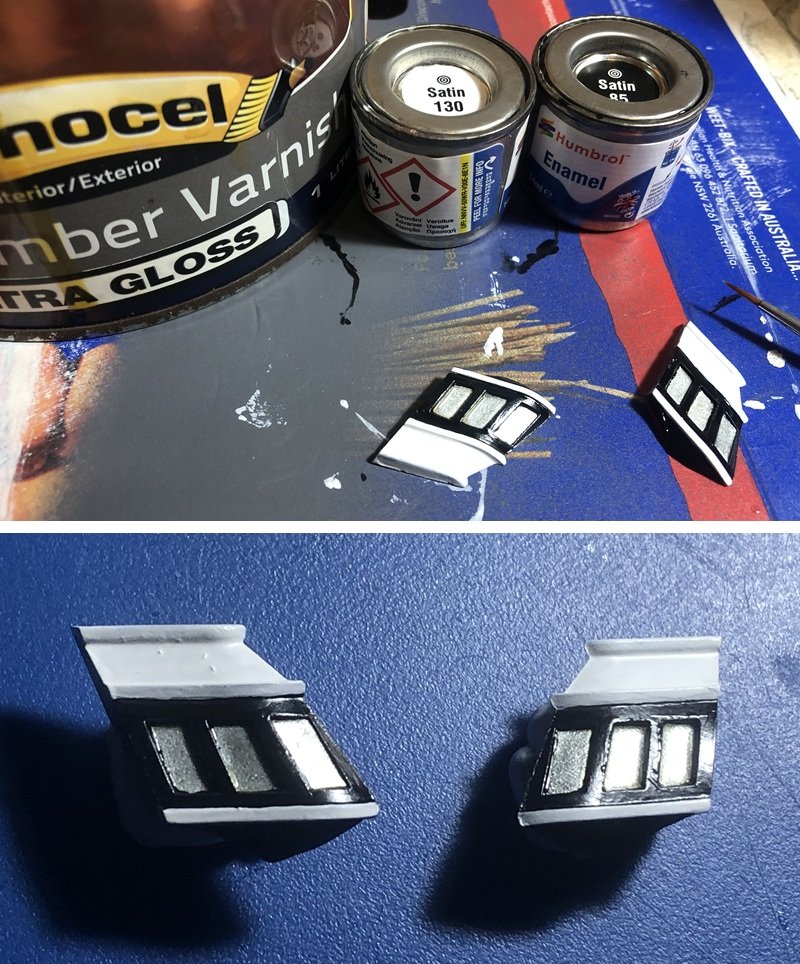
-
HMS Beagle by Tecko - OcCre - 1:60
Tecko replied to Tecko's topic in - Kit build logs for subjects built from 1801 - 1850
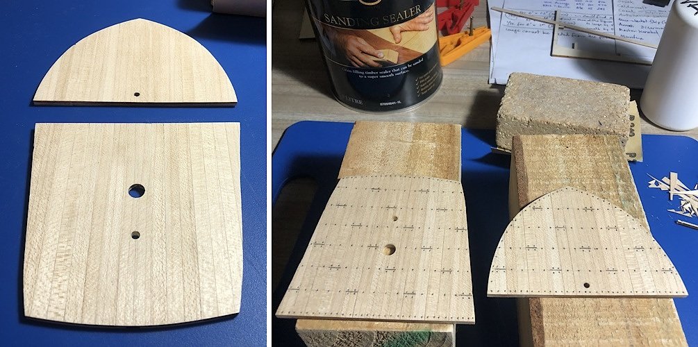
The doors are etched from brass, and they are supplied, in the kit, by OcOrer. So, I did not manage the doors at all, except the door knobs (pin heads).

