drobinson02199
-
Posts
1,021 -
Joined
-
Last visited
Content Type
Profiles
Forums
Gallery
Events
Everything posted by drobinson02199
-
 Ken -- For all I know, what you see IS the pop valve. None of the parts are given names, so one has to assume. I assumed whistle, but could be a pop valve. Regards, David
 -
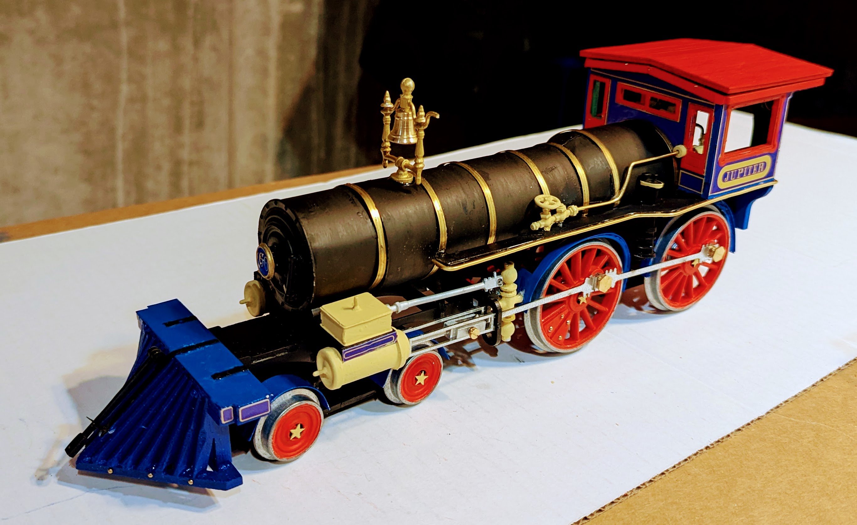
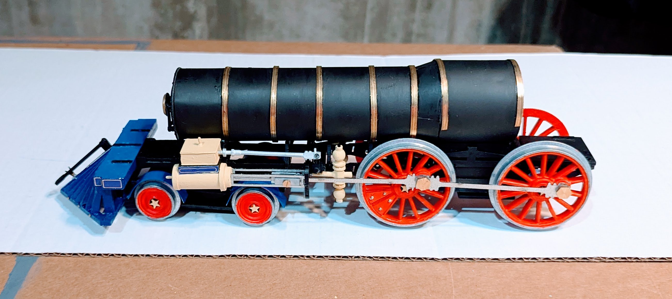
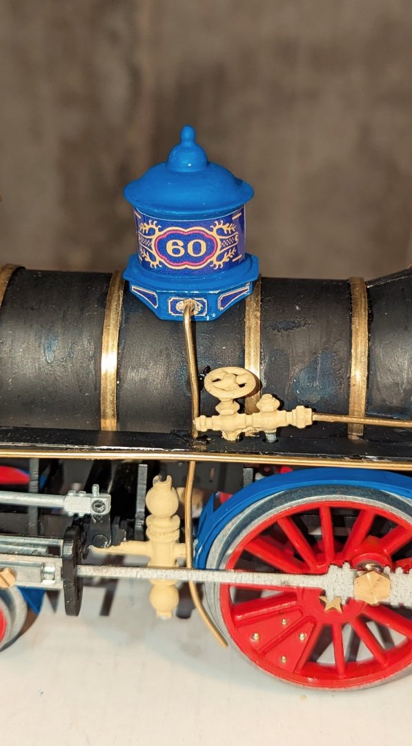
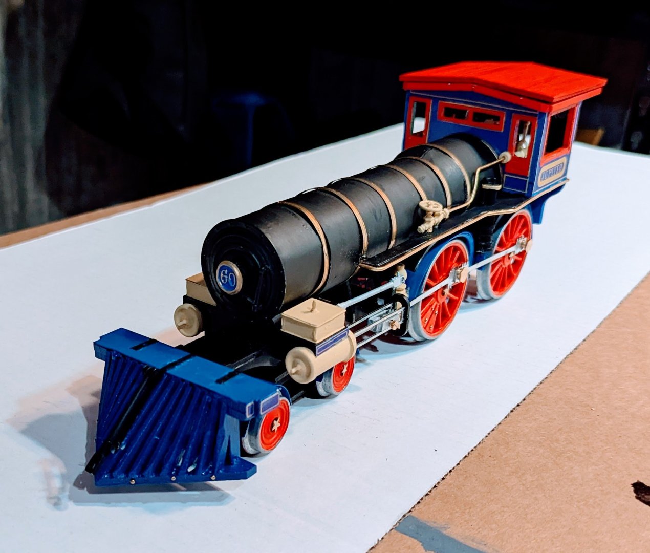
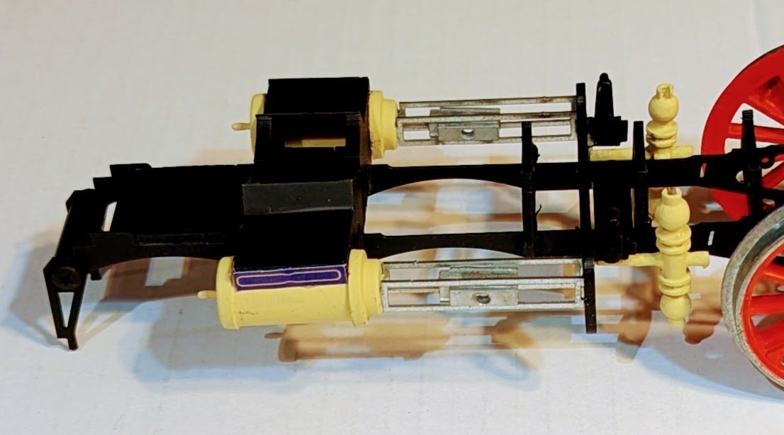
This next item includes the whistle at the top, but I'm at a loss regarding what the large cylinder is for. Perhaps our locomotive expert Andy can illuminate? BTW, the light colored areas on the black rods are not a sloppy paint job -- it's light reflection. [WHOOPS -- just looked again. They are areas where the paint came up as I pressed down. Will touch up.] 😋 Regards, David


-
Thanks, Andy!!
-
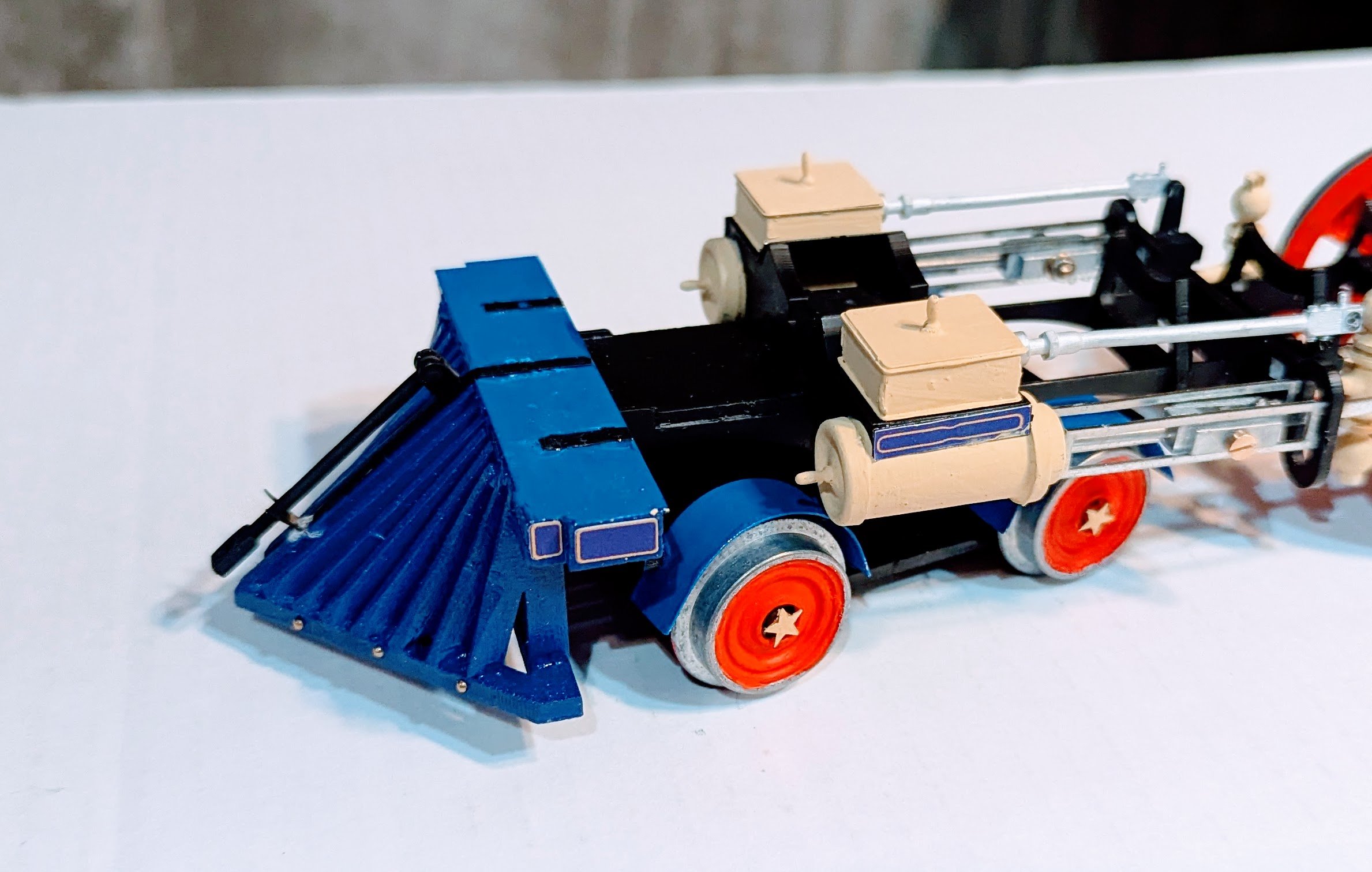
I'm not enough of a railroad expert to know for sure what this newly mounted item is -- the instructions, such as they are, don't give parts any real life names. But looking at it, I surmise that it was some sort of hot water blowoff device, and the routing of the exit tubes to the drive wheels makes me think it was for creating traction in snow and ice. Regards, David

-
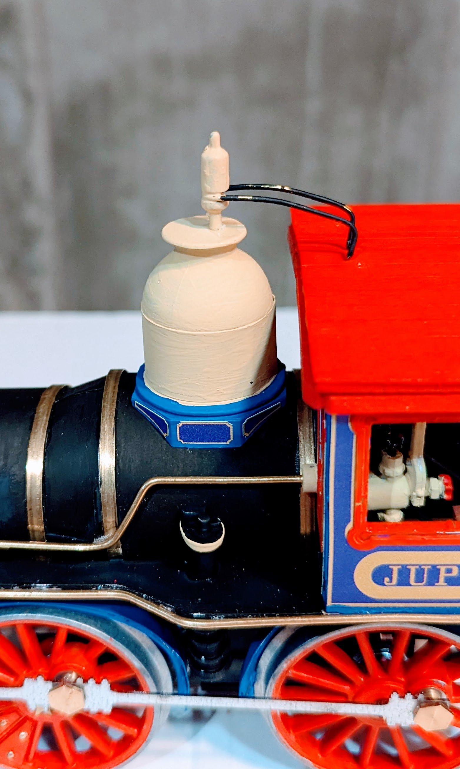
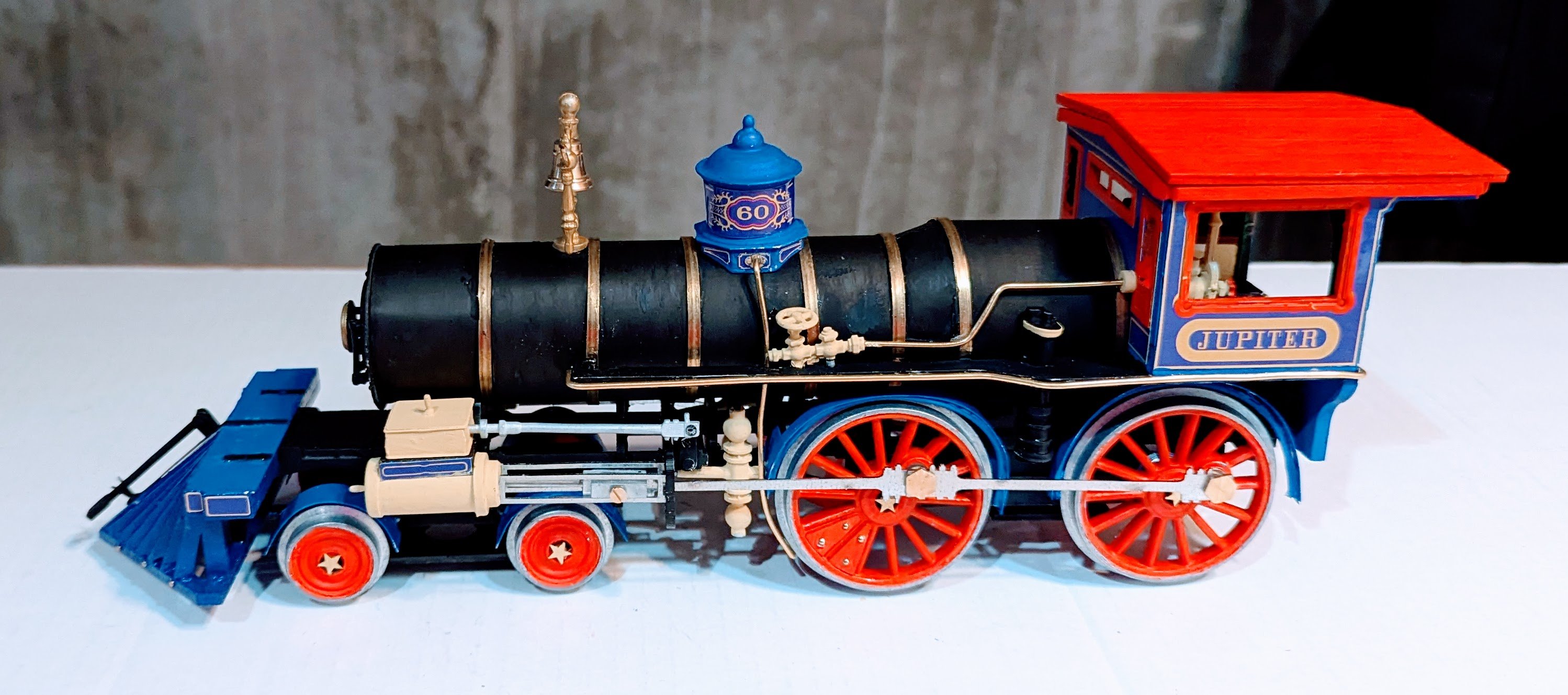
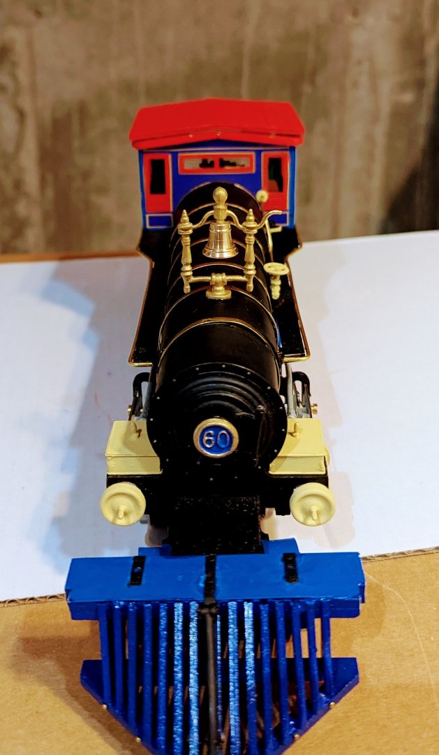
Bell and bell housing mounted. The color guidance in the manuals would have the bell housing the same beige color as the pistons, but I wanted to match the nice brass bell and brass axle, so I painted the housing gold and it all came out looking as good as I'd hoped. Regards, David

- 60 replies
-
- 11
-

-

-
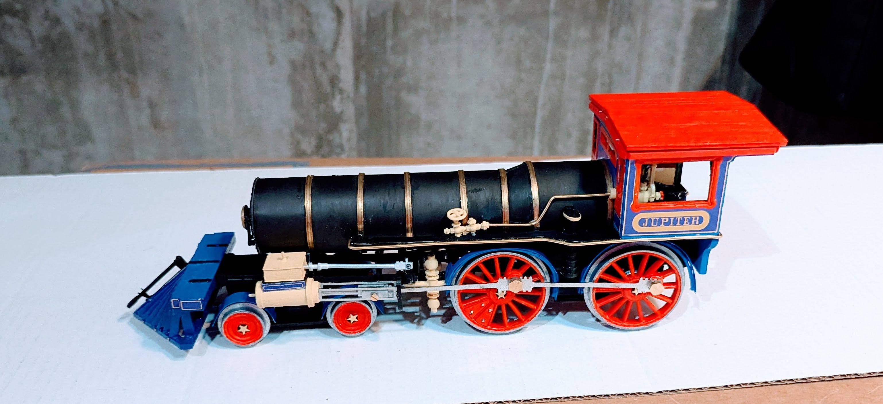
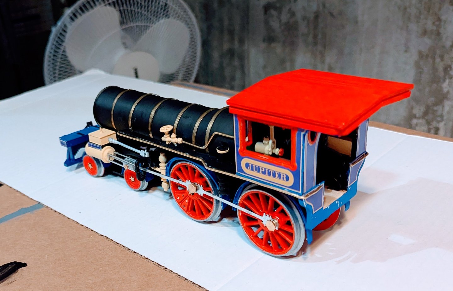
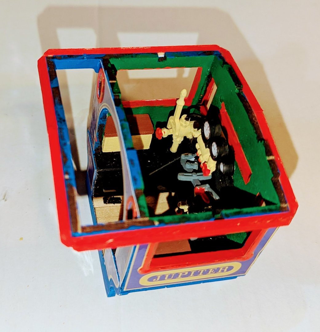
More work on the boiler; fenders added on main drive wheels, and boiler permanently mounted to the chassis. The instructions suggest that the roof be left removable to see the mechanics inside, but I'm going to eventually glue it down. You can see the mechanics through the window well enough, and later on there's a fitting from the boiler to the roof that looks like it would end up being loose and clumsy if fitted in such a way as to make the roof removable. So I'll glue it. The color pictures that are the guide to painting also suggest that the pipes be painted the same beige as the fittings, but I like the look of brass and it works well here. Regards, David
- 60 replies
-
- 11
-
-
-
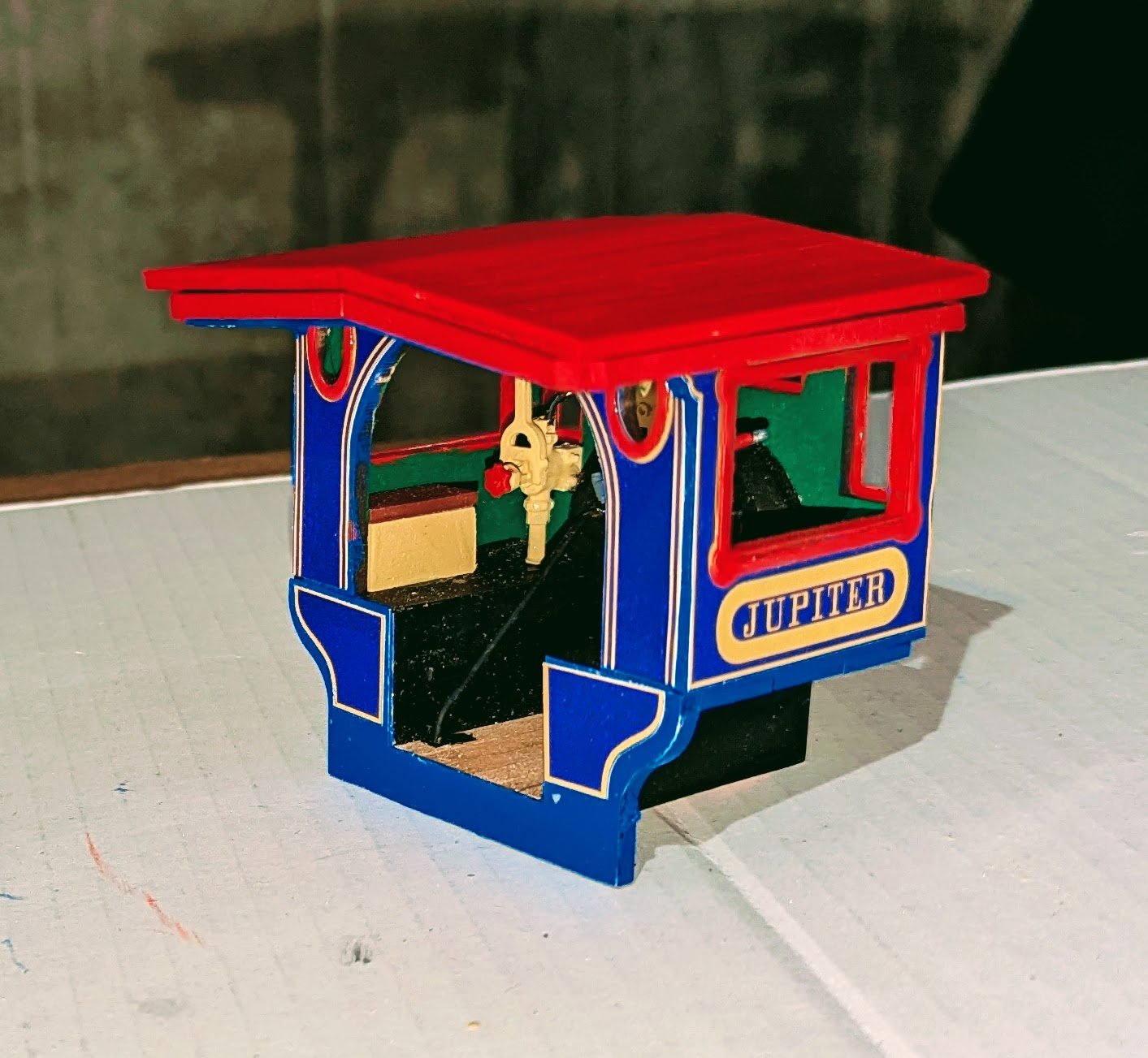
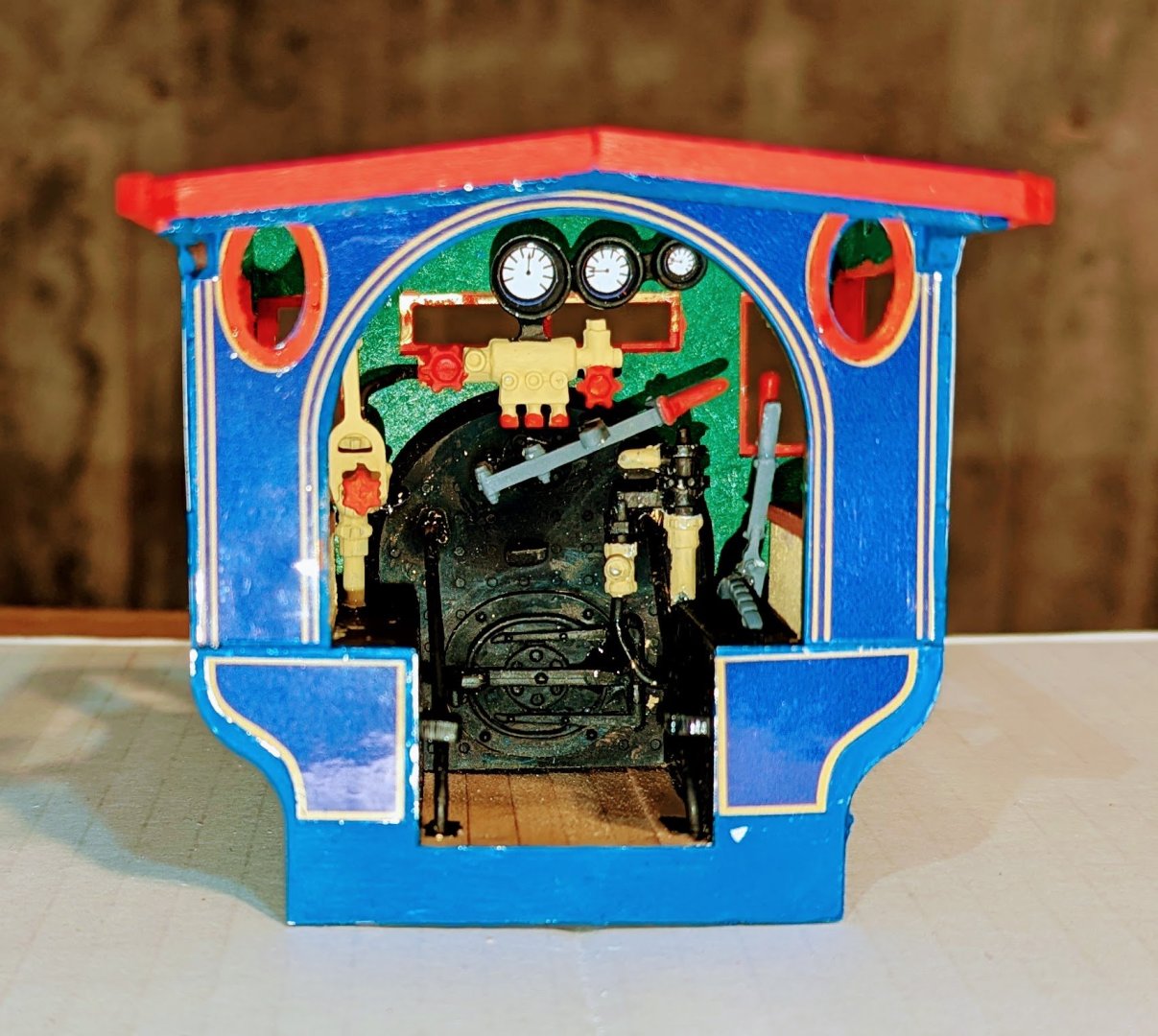
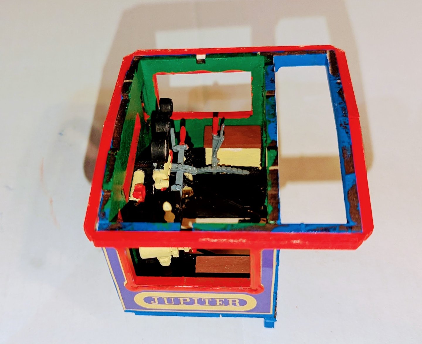
Engineer's cab with removable roof. Regards, David

-
Nice boiler and engine control detail on the inside of the cab. The perspective for one of the parts is off in the drawings, so you have to hand fit some things. Regards, David
- 60 replies
-
- 12
-
-
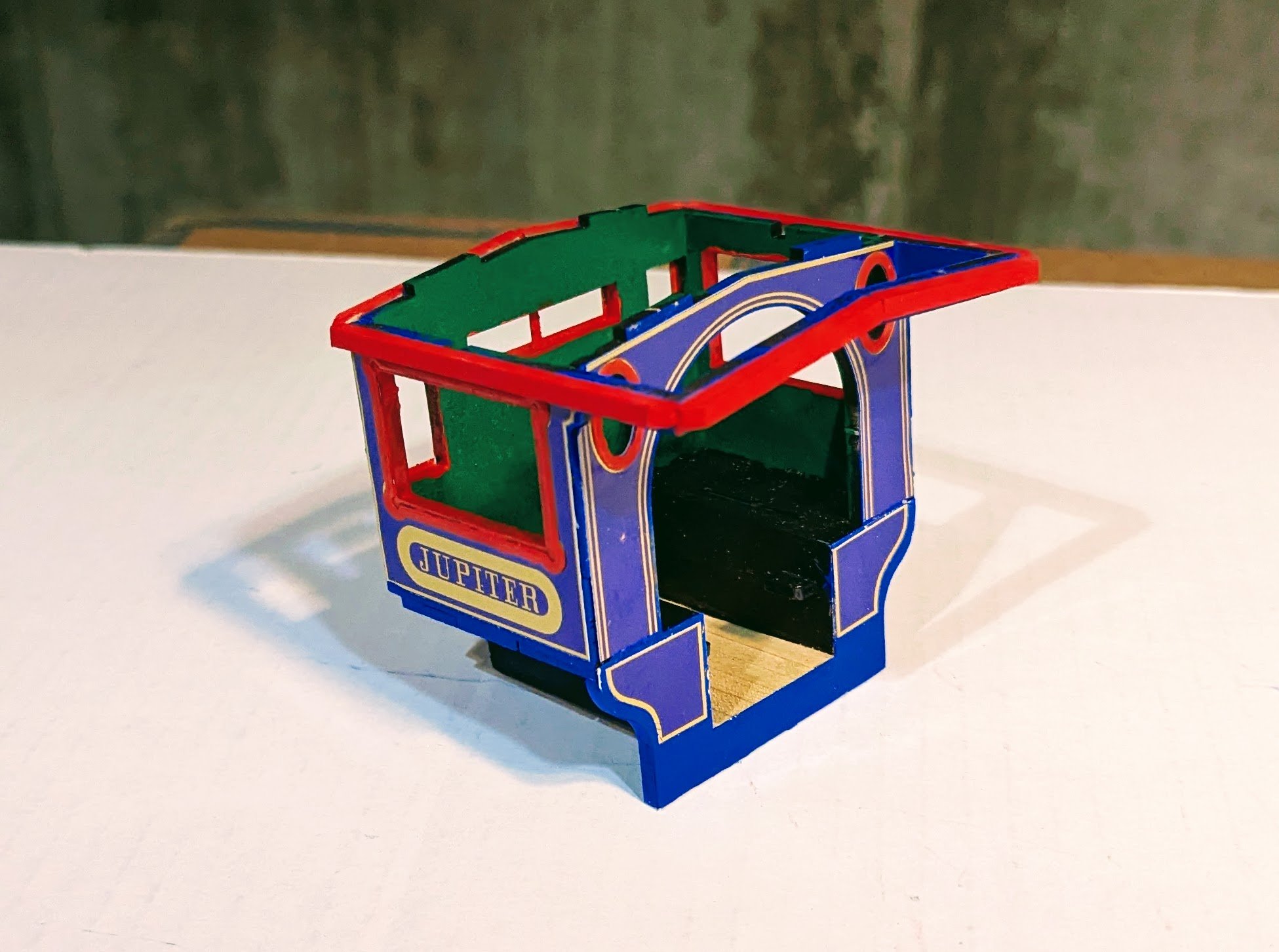
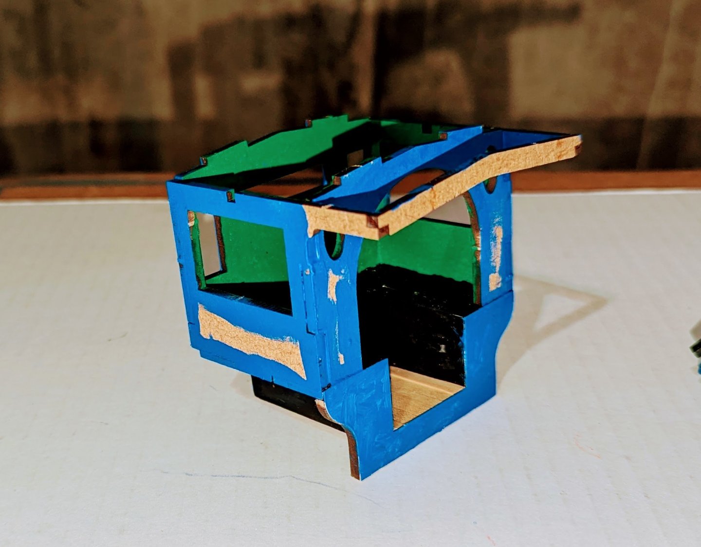
Working on the engineer's cab: The decals don't overlap precisely, so I painted all the edges of the cab with blue, where they don't overlap or where they come up to window openings. The pics show the cab after the blue paint but before decals, windows and trim, and then after all that. There is an anomaly in the instructions. The diagrams call for planking the sides of the cab with the same planking you see on the floor, then painting that and then applying decals. But the decals referenced in the build diagrams cover much less than the ones in the kit, and the color pictures show the larger decals applied to the walls without planking. So I skipped the wall planking. Regards, David

- 60 replies
-
- 10
-
-
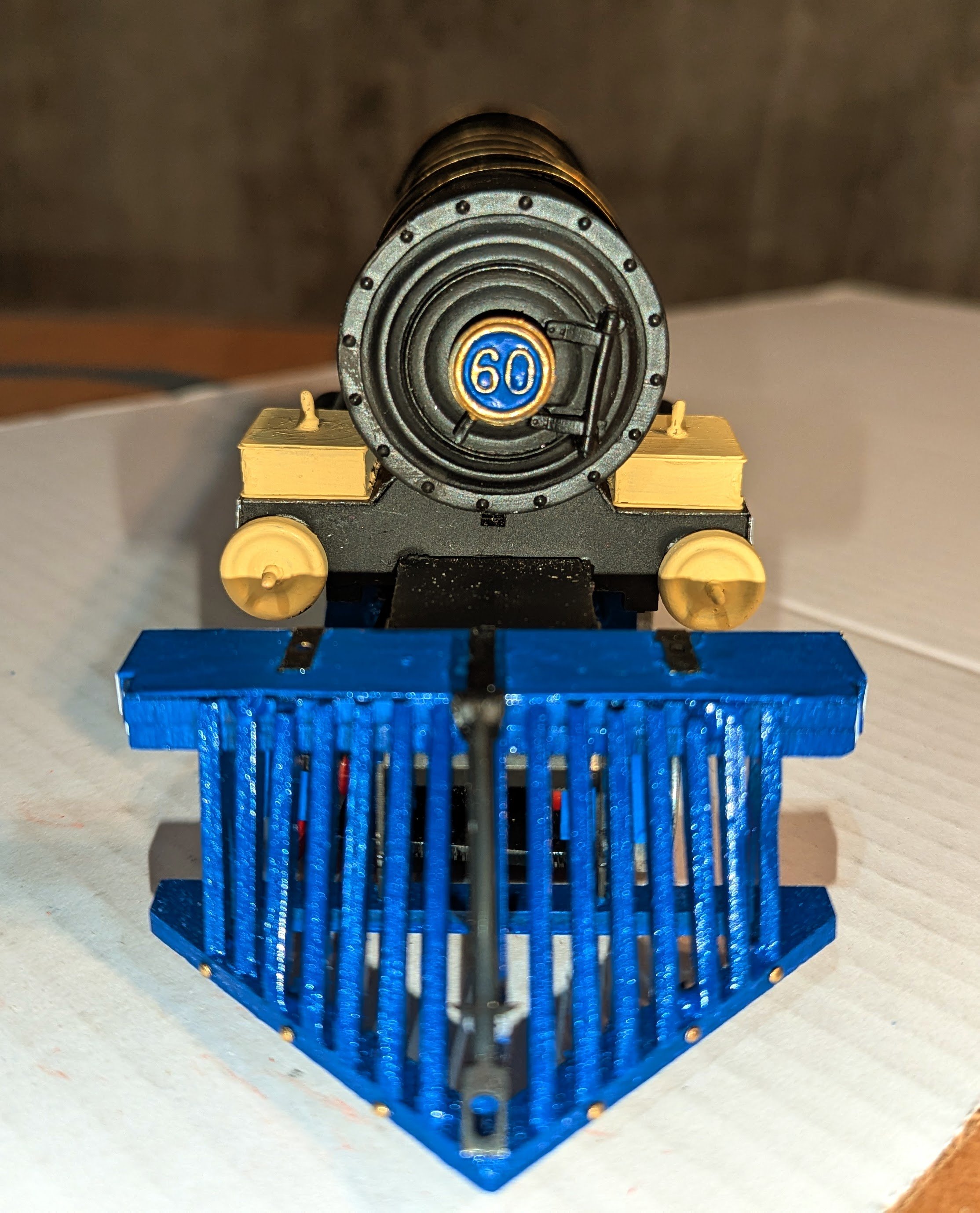
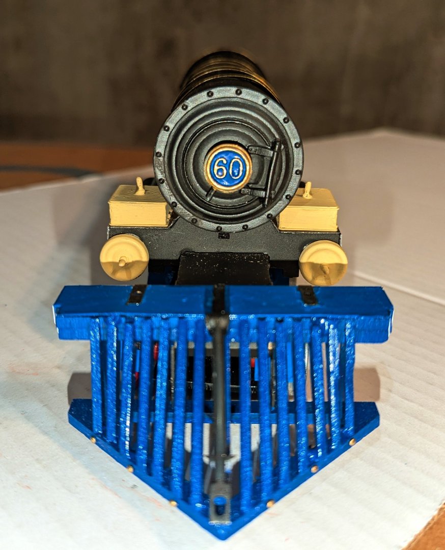
Canute: I think it's just lighting. I used flash on the front view. All of the boiler paint is just flat black. Regards, David
-
The boiler is assembled, painted and dry-fitted to the chassis (it's permanently installed later on). Here's what I learned the hard way with the boiler. I assembled it and spray painted it black. But when I went to install the brass bands, I found that it was almost impossible to avoid messing up the paintwork. So what you see is spray painted, bands installed, and then the entire thing hand-painted. I think that's the only way to do it. I found that I had to really twist the brass bands tight and take ALL of the spring out of them relative to the boiler circumference. If there is any spring, it will pull off the spray painted layer. Then you have to go in with a file, rough up that part of the metal shell, and re-glue. Even with the later bands with all of the spring removed, the gluing process still leads to marring of the boiler finish. I still recommend spray apinting the boiler first, as it creates an adhesion surface and leads to a nice hand-painted job. Regards, David

- 60 replies
-
- 14
-
-
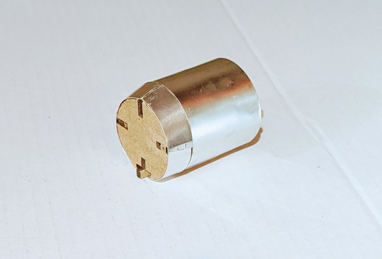
I've put the metal sheeting on the rear boiler section. I wasn't getting any adhesion with super glue at first, even with the laser burns sanded down, but then I took my rotary tool and sanding drum and roughed up the inside surface of the metal, and that did the trick. Adheres quickly. Regards, David
-
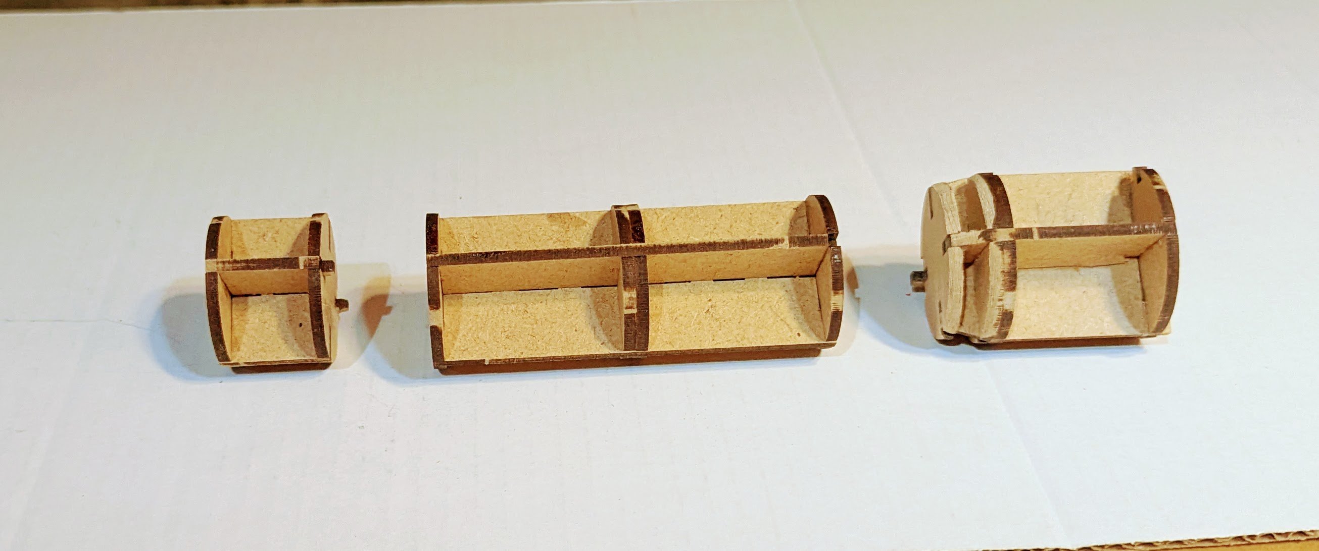
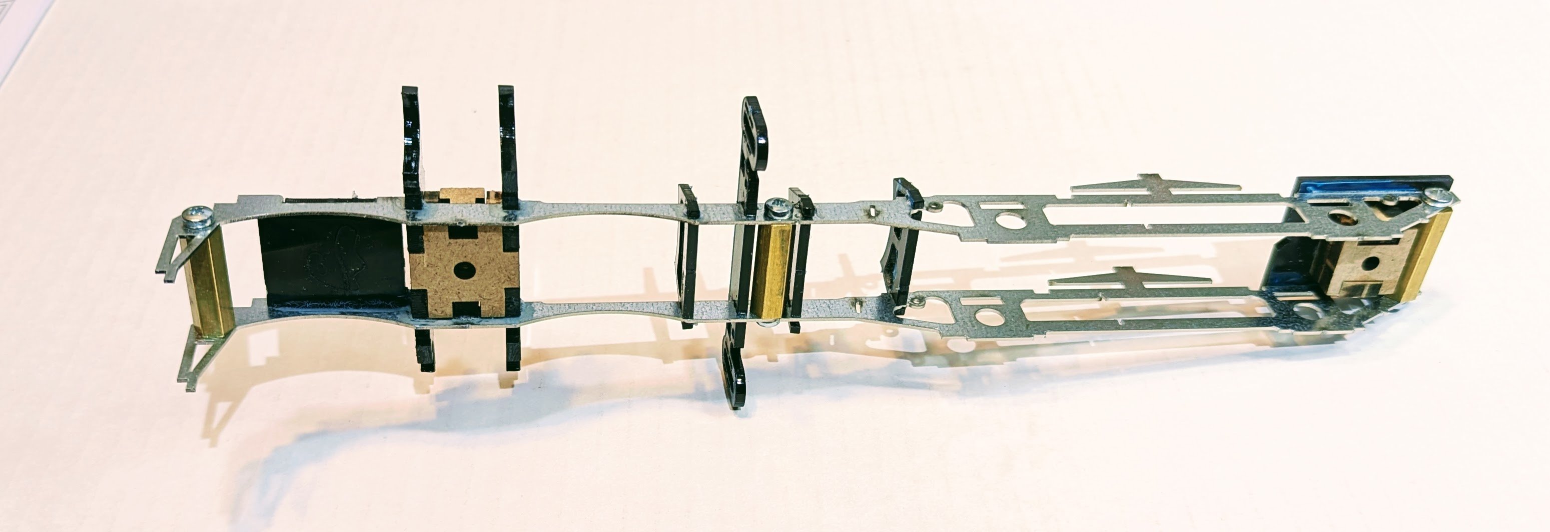
Here are the frames for the boiler assembly. I messed up the one on the right -- dry-fitted everything and then when I took it apart and went to glue it got careless and swapped some piece positions. Fortunately, the damage is recoverable -- I just lose some alignment tabs which I don't absolutely need. But bonehead move. Regards, David
-
The front trucks are assembled and mounted to the main chassis. And they swivel! Regards, David

- 60 replies
-
- 11
-
-
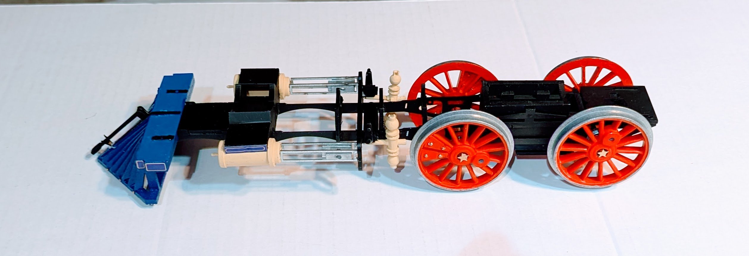
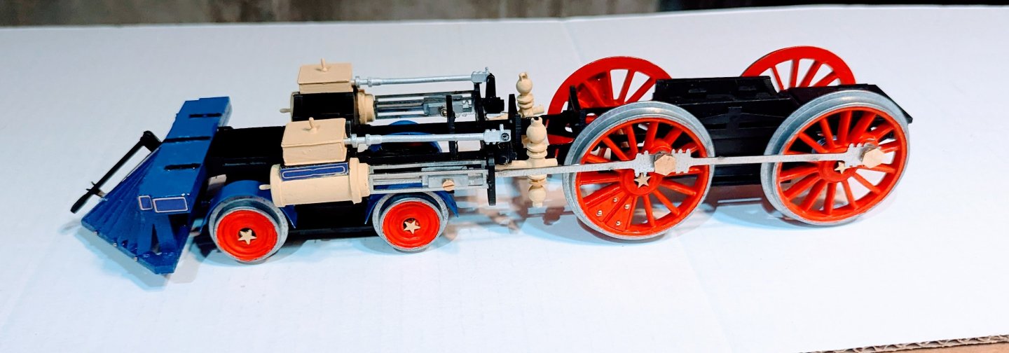
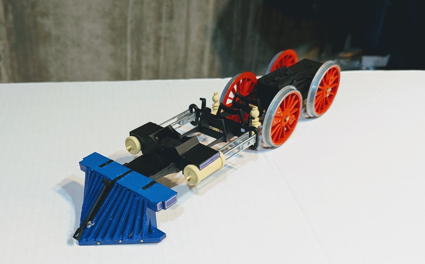
Built and mounted the cowcatcher; stars on the wheel hubs. You may see that the top frame of the cowcatcher is a lighter blue than the rest. That's because I used a spray, but needed to touch up the top surface and my brush blue is a bit lighter. It's a bit more noticeable in person. I've decided that it's actually OK, because there will be blue items on the engine that I will brush paint, so this provides a transition to those. Regards, David

- 60 replies
-
- 10
-
-
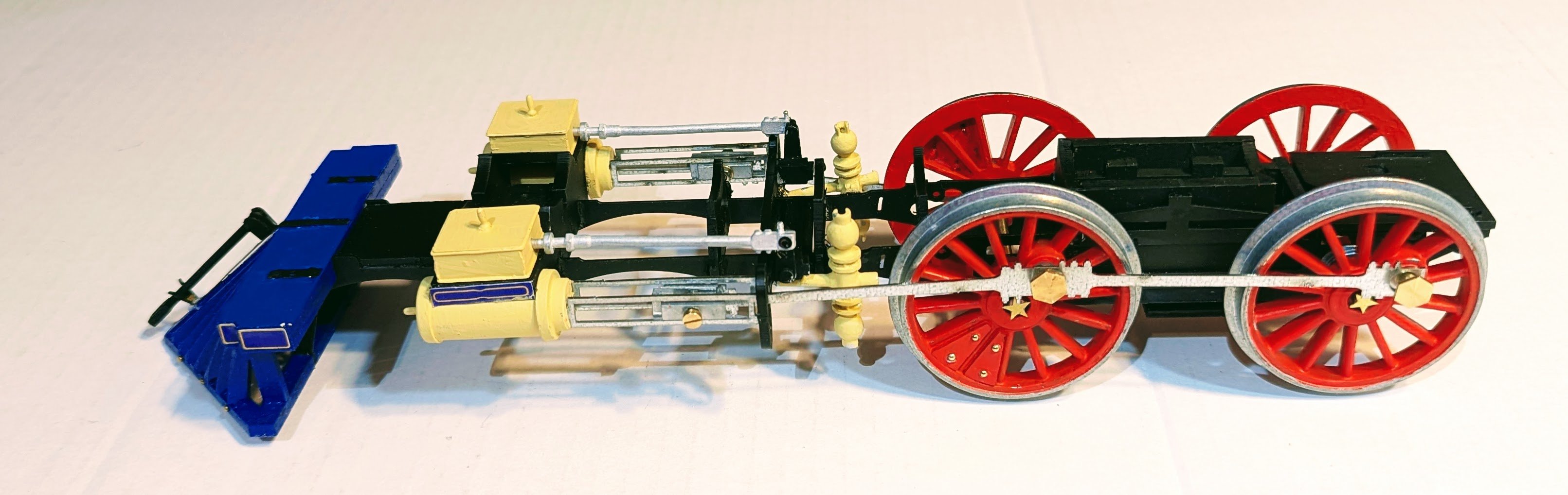
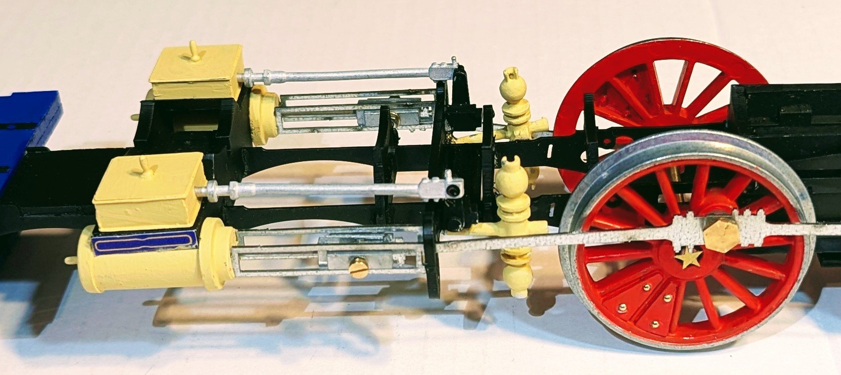
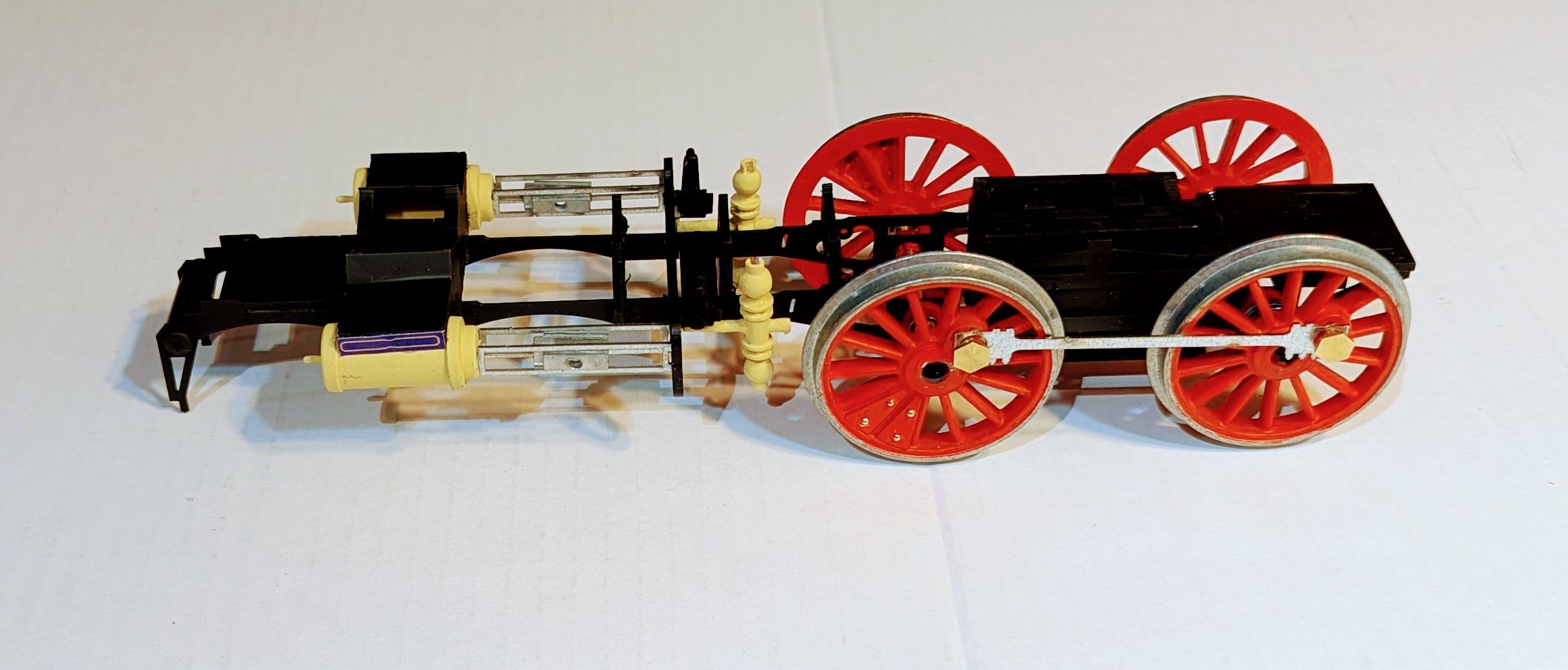
Pistons and some other fittings assembled and installed. Regards, David

-
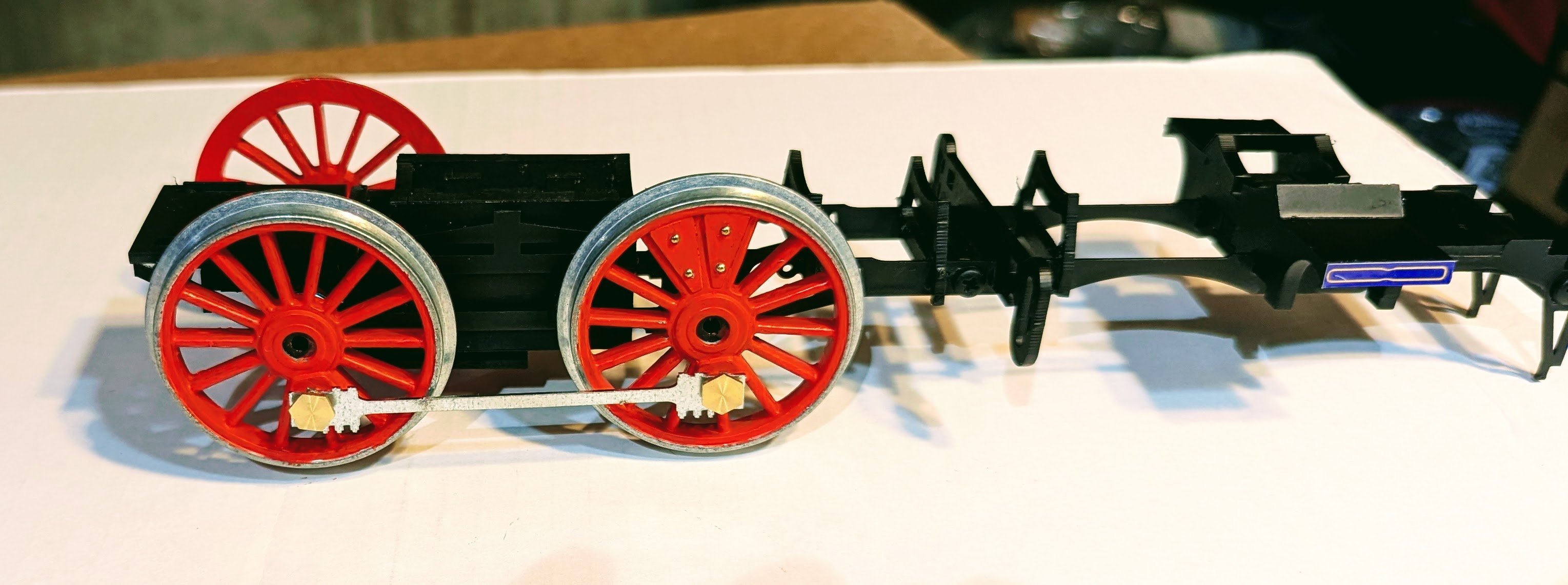
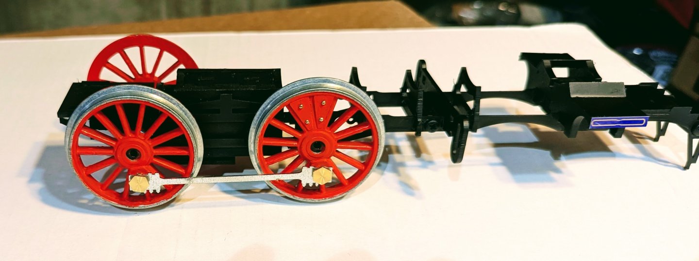
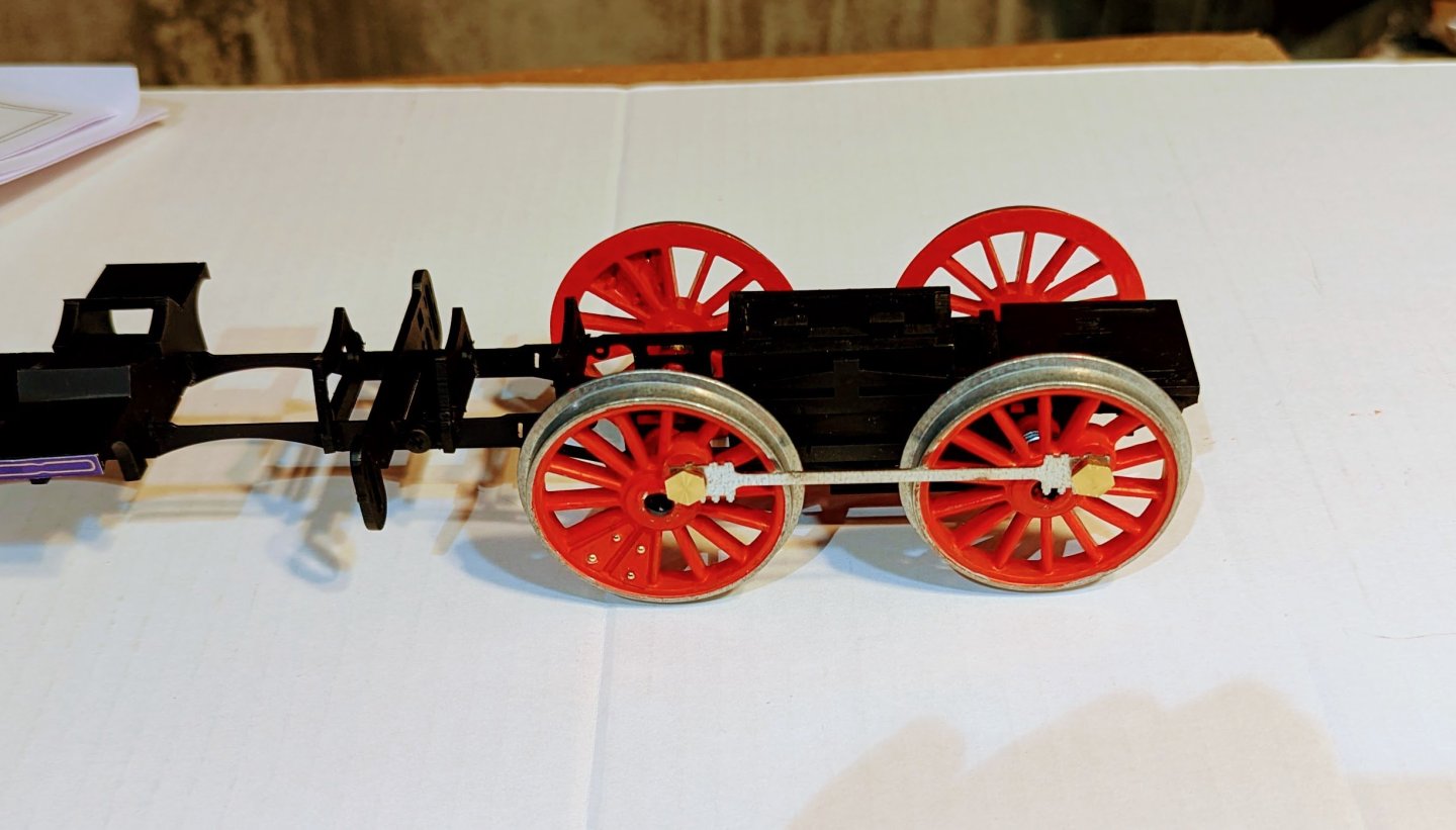
Mounting the main driver wheels: the front and rear wheels on each side have to be aligned in terms of rotation, and the wheels on the opposite side are offset 90 degrees. So even though it's not called for yet, I used the linking rods temporarily to align one side, then attach the third wheel offset 90 degrees, and then the fourth aligned with it. It all works when you rotate the wheels, although the last thing I'll want this model to do is roll freely once it's finished. Regards, David
- 60 replies
-
- 11
-
-
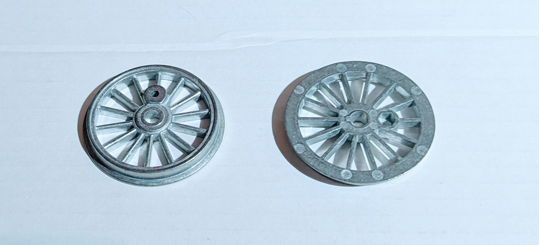
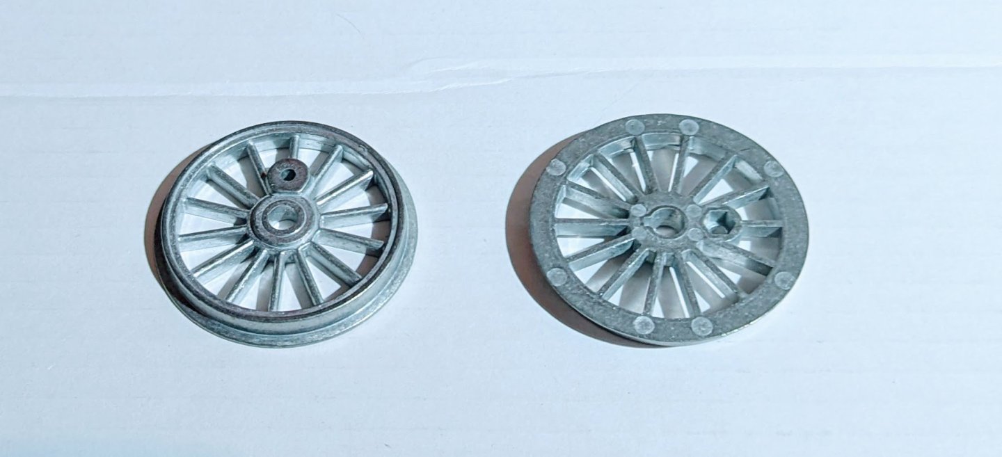
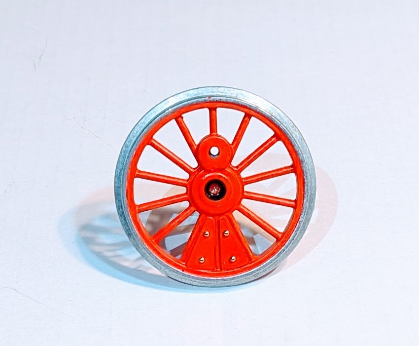
Started on the main driver wheels. These are cast metal, and need to be hand-painted. Here's a before and after. Regards, David
- 60 replies
-
- 11
-
-
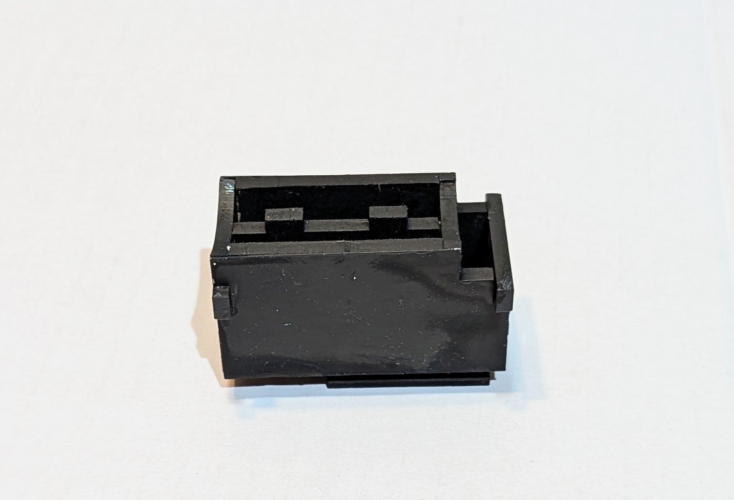
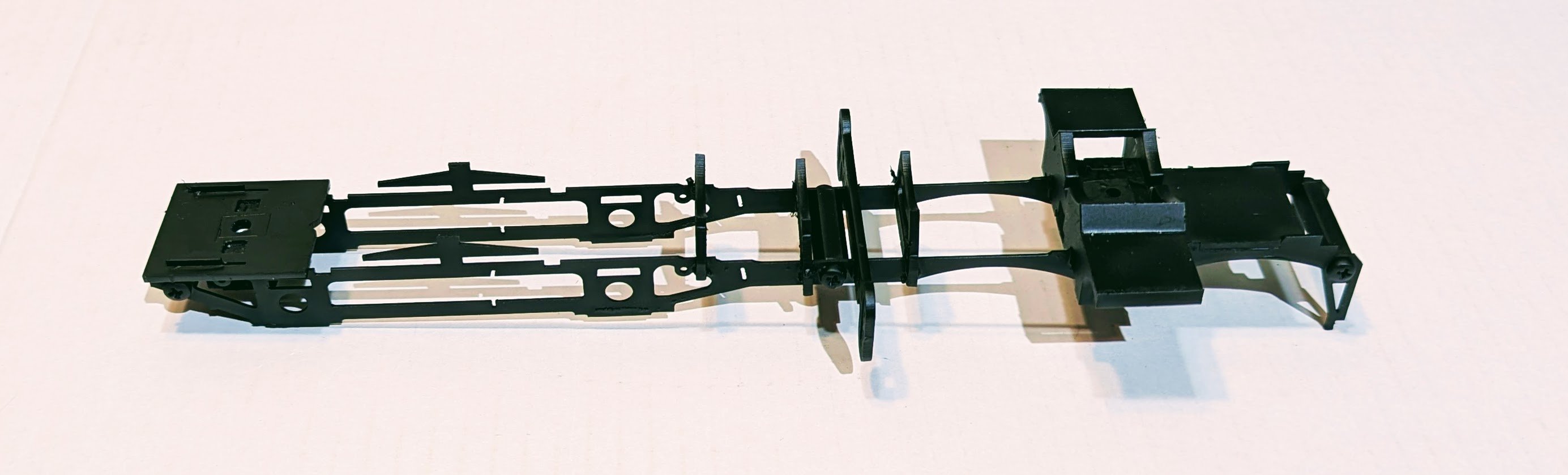
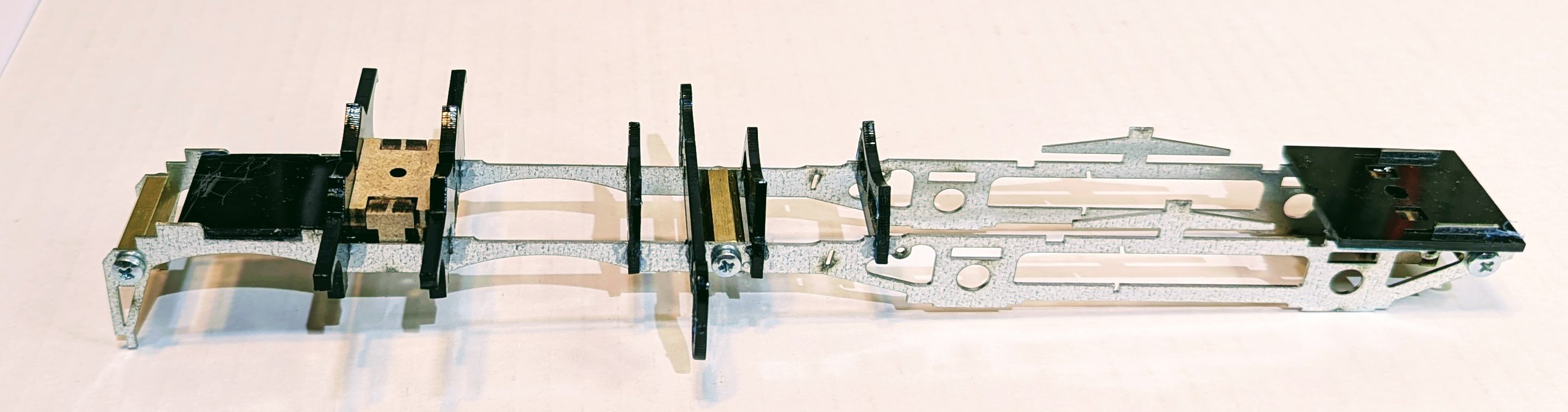
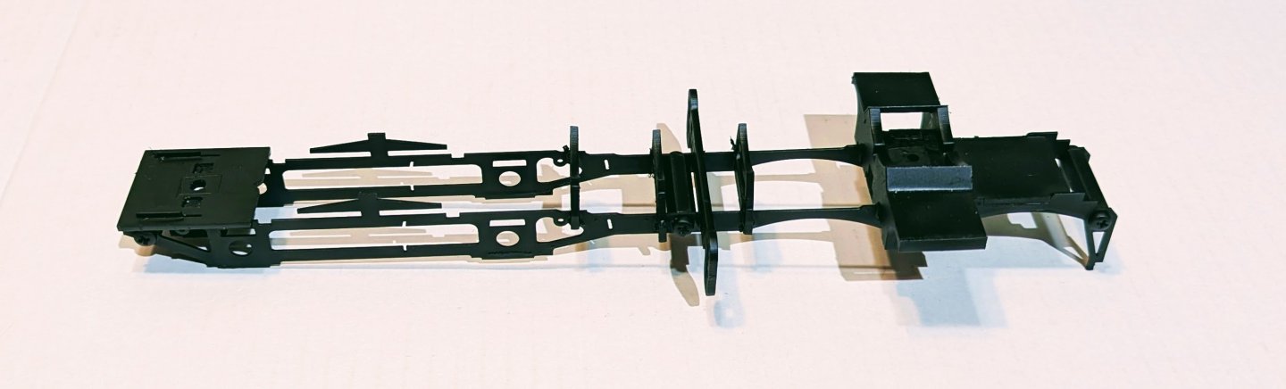
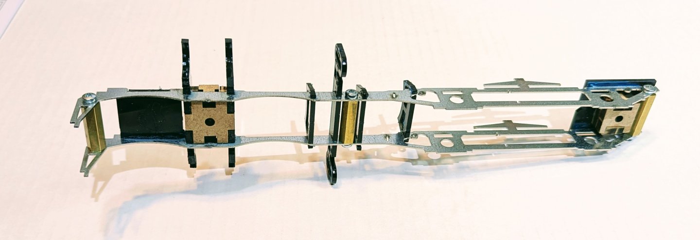
Here's a small assembly finished, and mounted in the chassis. Regards, David


-
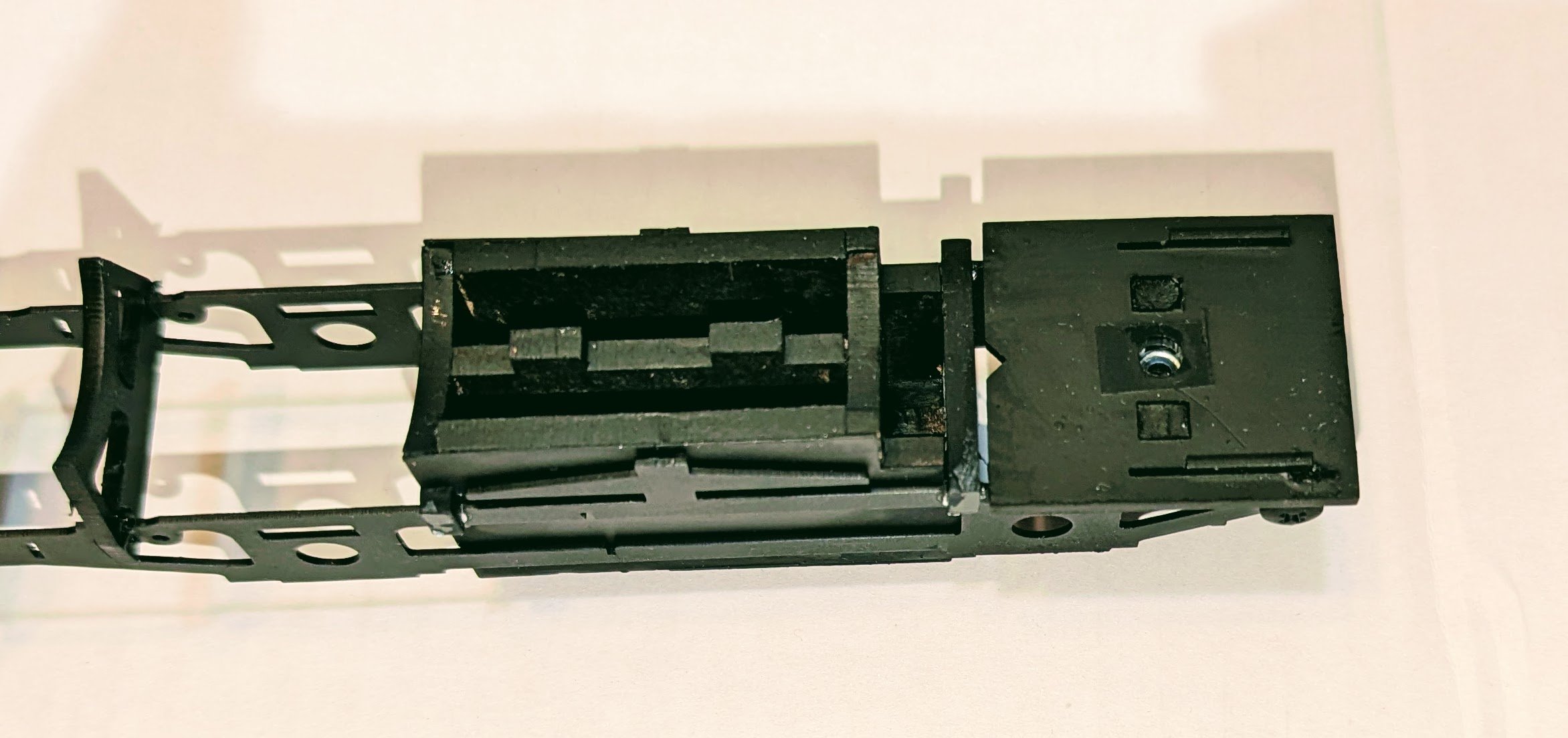
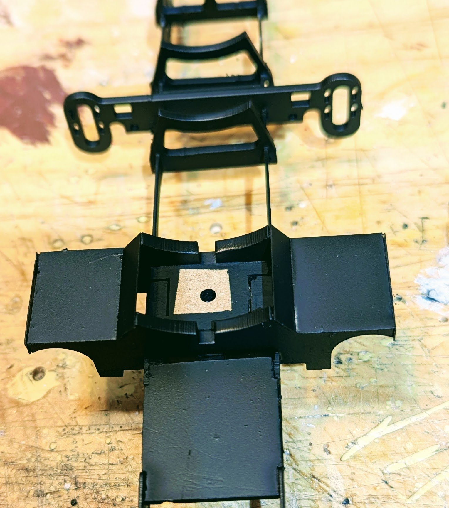
Greetings from the learning curve. After I posted the above pic as "completed assembly", I looked again at the instructions, correlated two different sheets together, brushed up on my sign language, and realized that I was missing a few final parts, but more significantly, needed to paint the whole thing black. I think I have maybe finally decoded the instructions logic and symbology. Fortunately, before doing that I realized that there are two bolts imbedded in the assembly that needed to be taped over so they wouldn't get clogged. Nothing in the instructions about that. You can see that in the first picture after I removed the tape. I then hand-retouched those areas plus some others the spray missed. Painted assembly also included below. Regards, David

- 60 replies
-
- 11
-
-
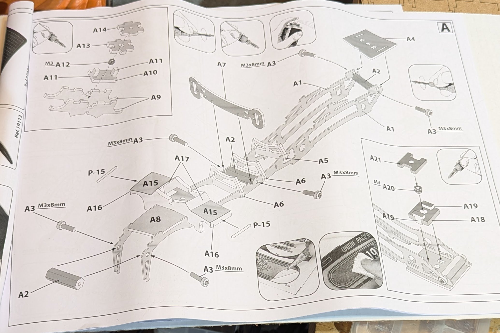
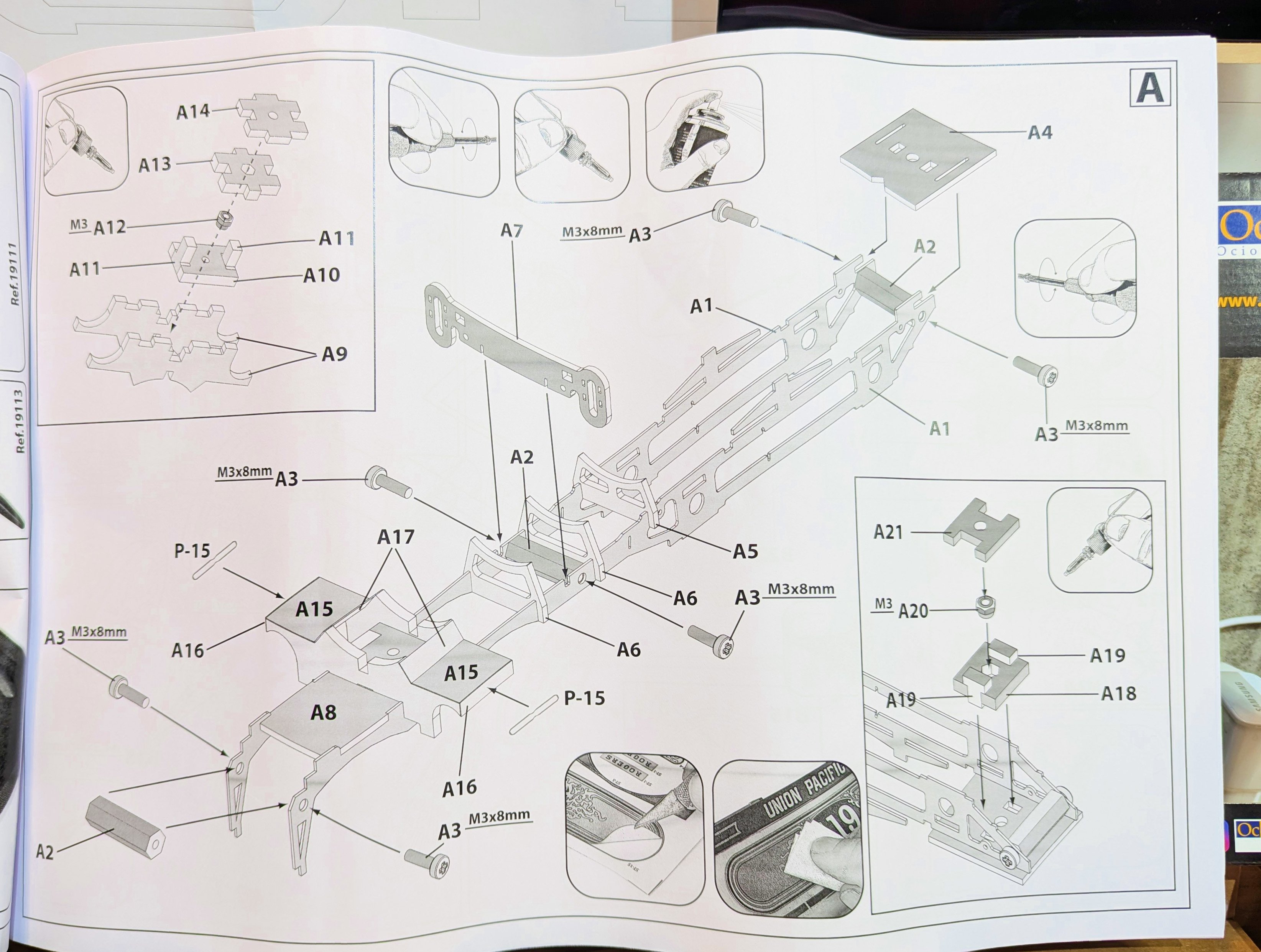
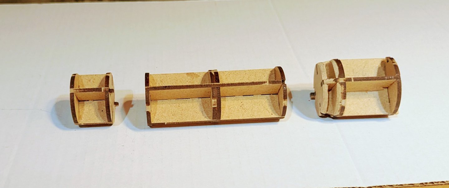
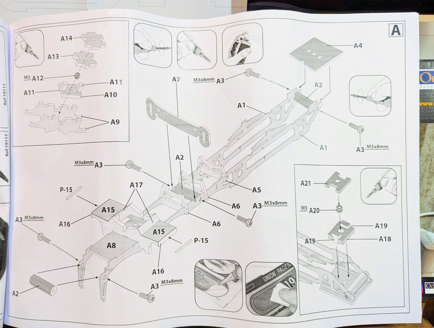
Here's the first assembly done. I've included a picture of the instructions page that covers this assembly, plus a couple of views of the finished product. It uses metal, a thick black plastic, and wood. All of the parts are extremely sturdy and heavyweight. Thanks, David


- 60 replies
-
- 13
-
-
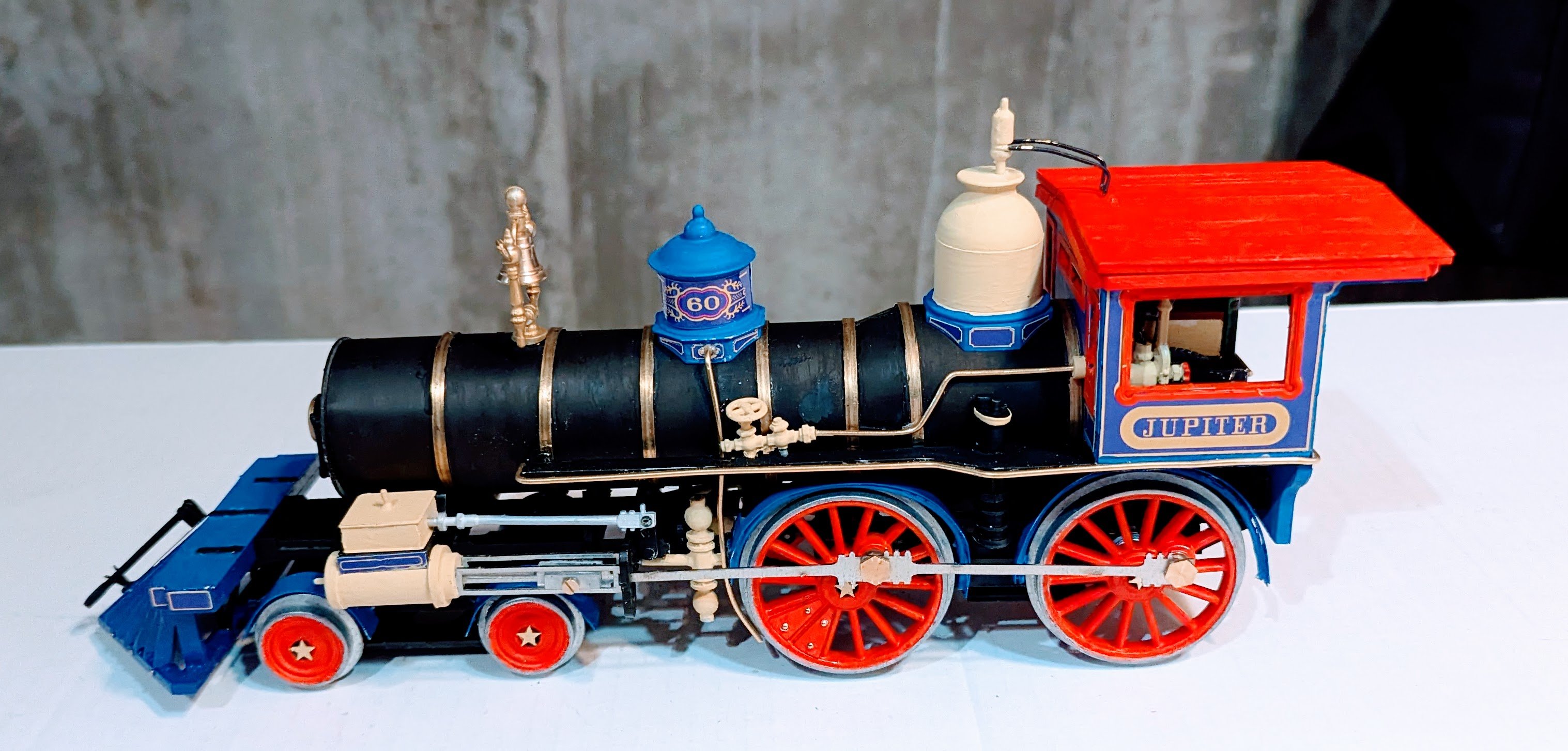
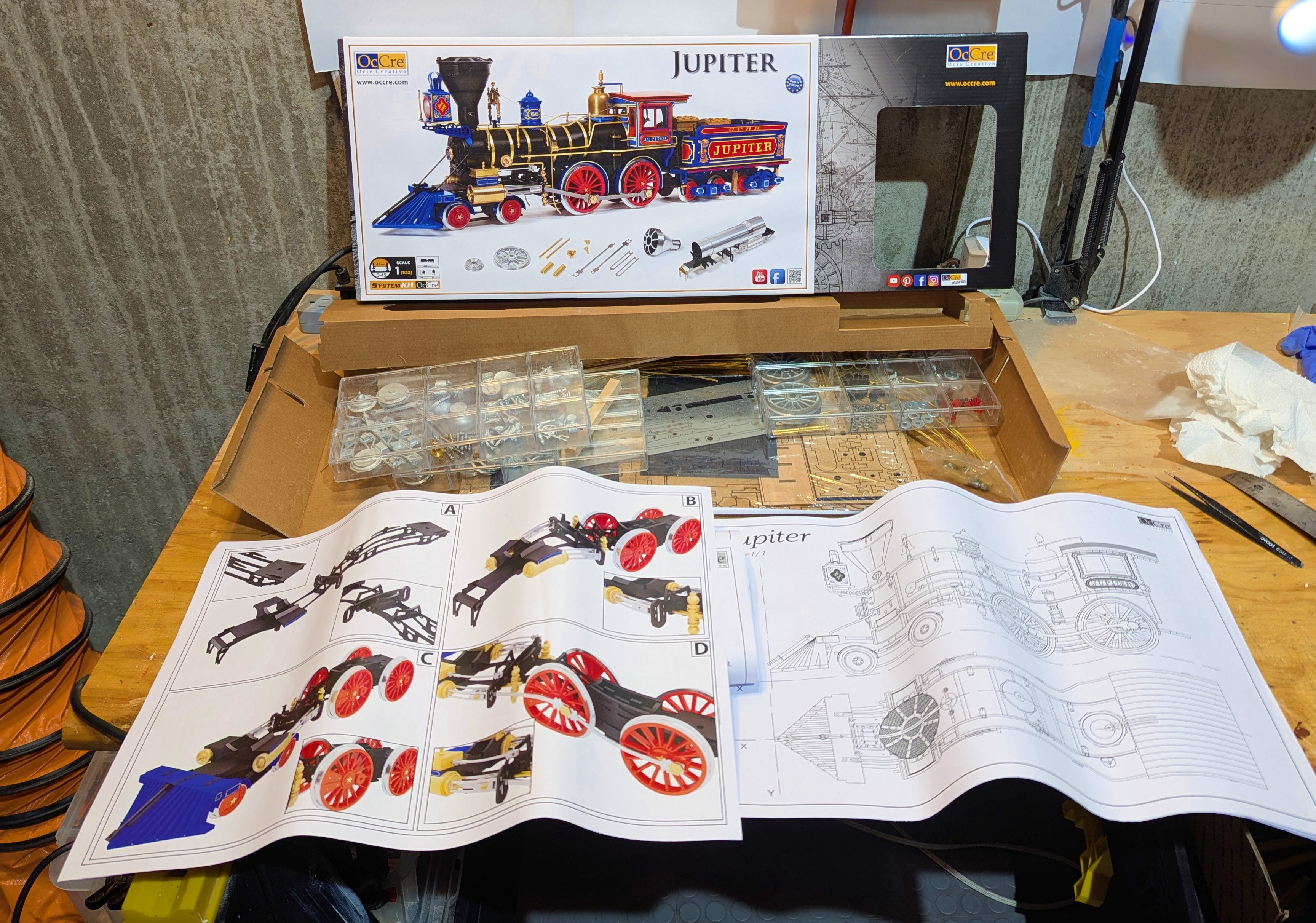
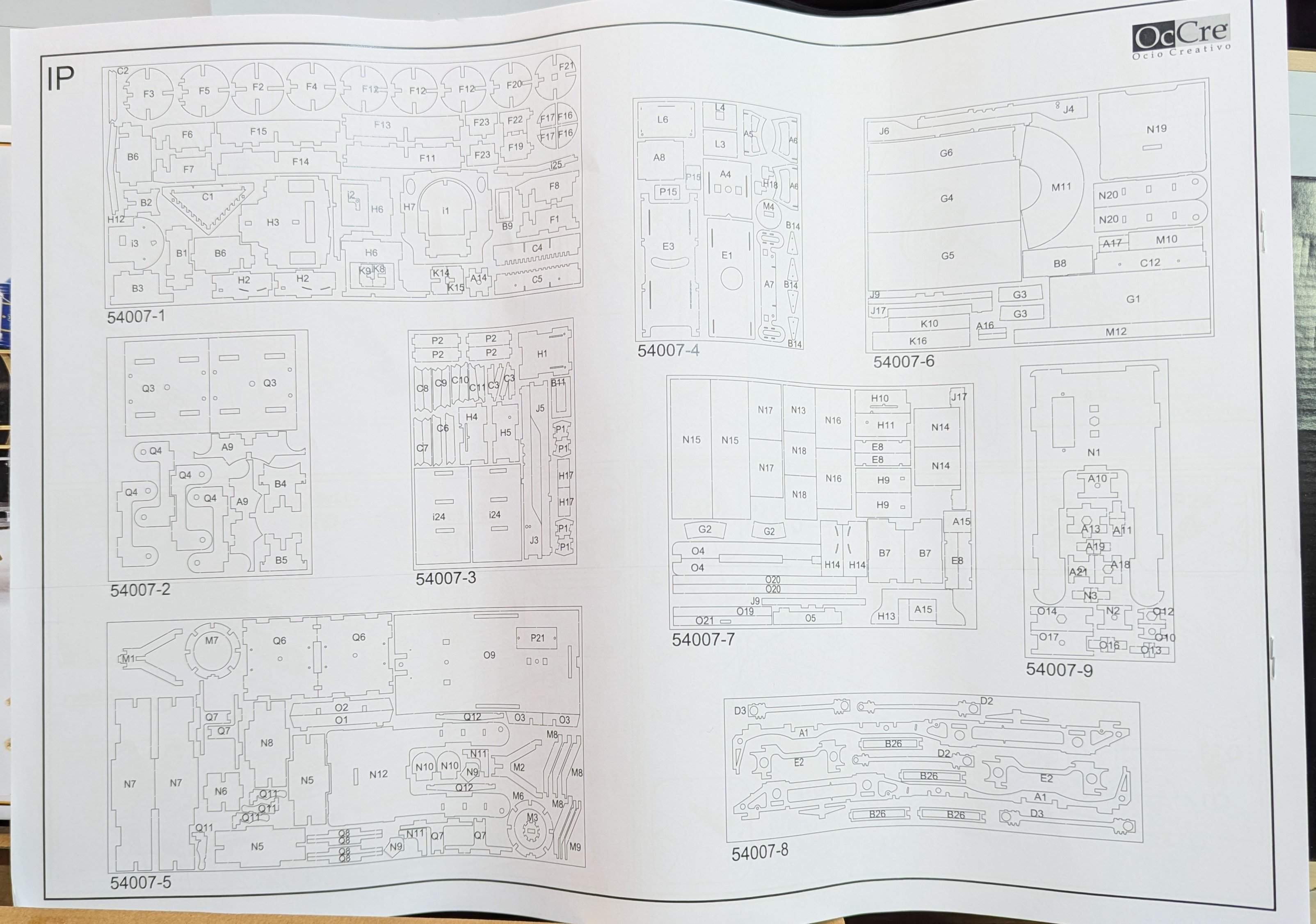
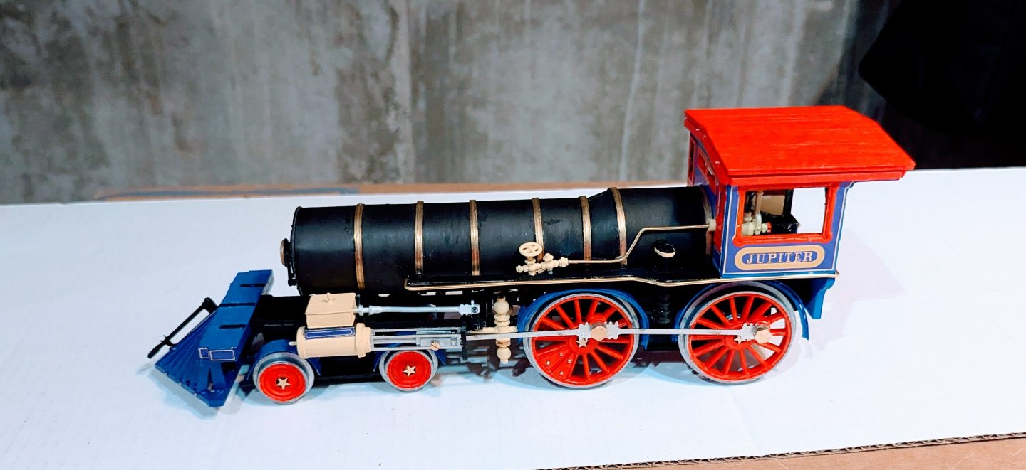
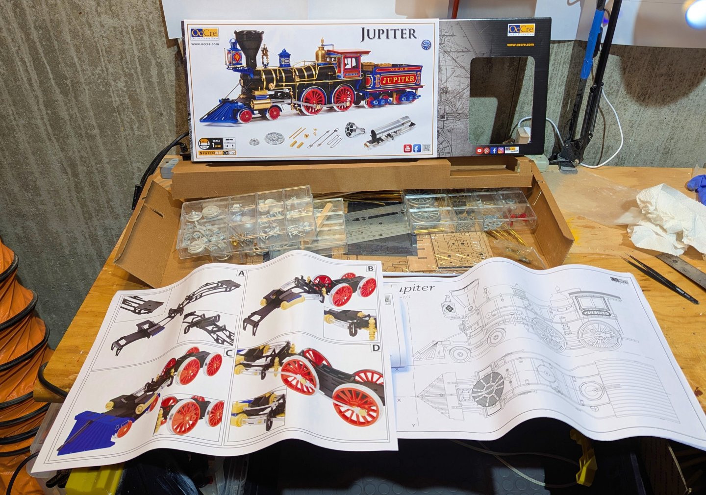
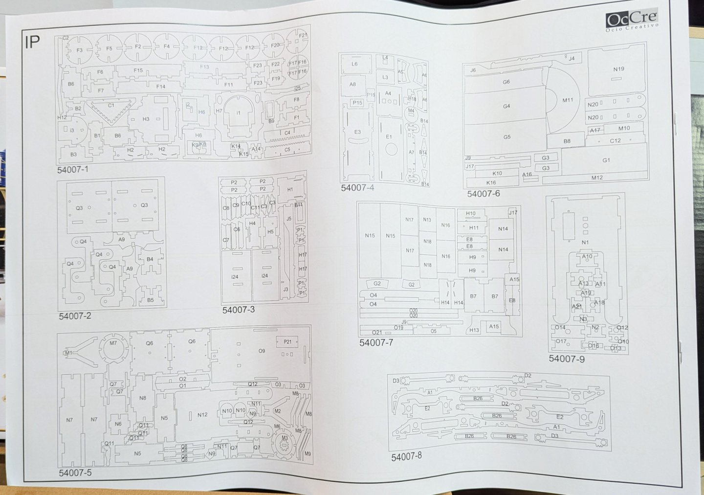
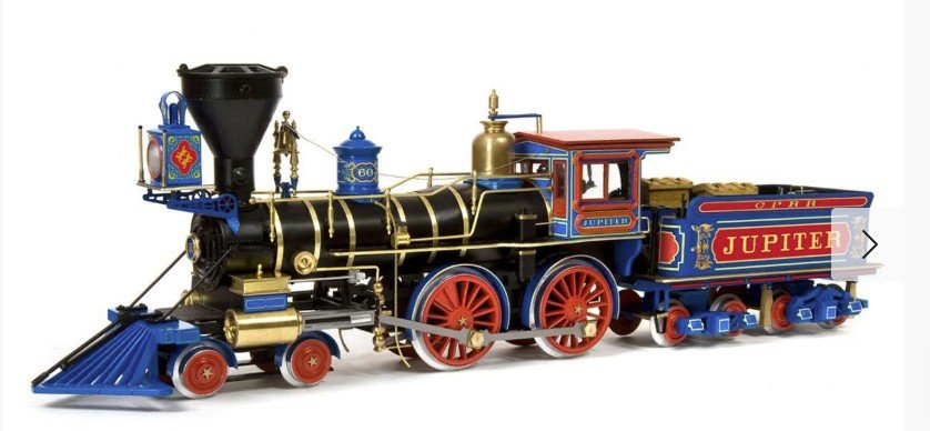
Taking a break from ships to build this striking locomotive model from Occre. The Jupiter represented the Central Pacific Railroad at the "Golden Spike" ceremony at Promontory Summit when the two parts of the US Transcontinental Railroad were linked in 1869. Here's my "what's in the box" post, starting with an overview of box contents: laser cut wood sheets, photo etched sheets, and metal parts. I have also added two pictures that show the instructions logic. Other than a page of overview comments on building approaches, there aren't any step-by-step written instructions. Instead, there's a page that shows how to label the laser cut parts, and then a set of pages that show assembly in pictoral form. So this isn't a kit for beginners. I'll label all the parts on a sheet the first time I need to access that sheet. Regards, David
- 60 replies
-
- 12
-
-
I decided for variety that I'd build one of the beautiful wood model locomotives that Occre supplies. Since I can't post a build log for that here, I have created a group Facebook site for it under the title "Occre Jupiter DGR". It's public, so if you are interested you can go to Facebook, search that title, and see what I post. If you join the group, you'll get new posts on your own Facebook page. There's not a lot there right now as I just wanted to create the site as a reference to post here. Here's a picture of the Jupiter, which was one of the locomotives present at the driving of the "golden spike" that completed the US Transcontinental Railroad in 1869. Regards, David
-
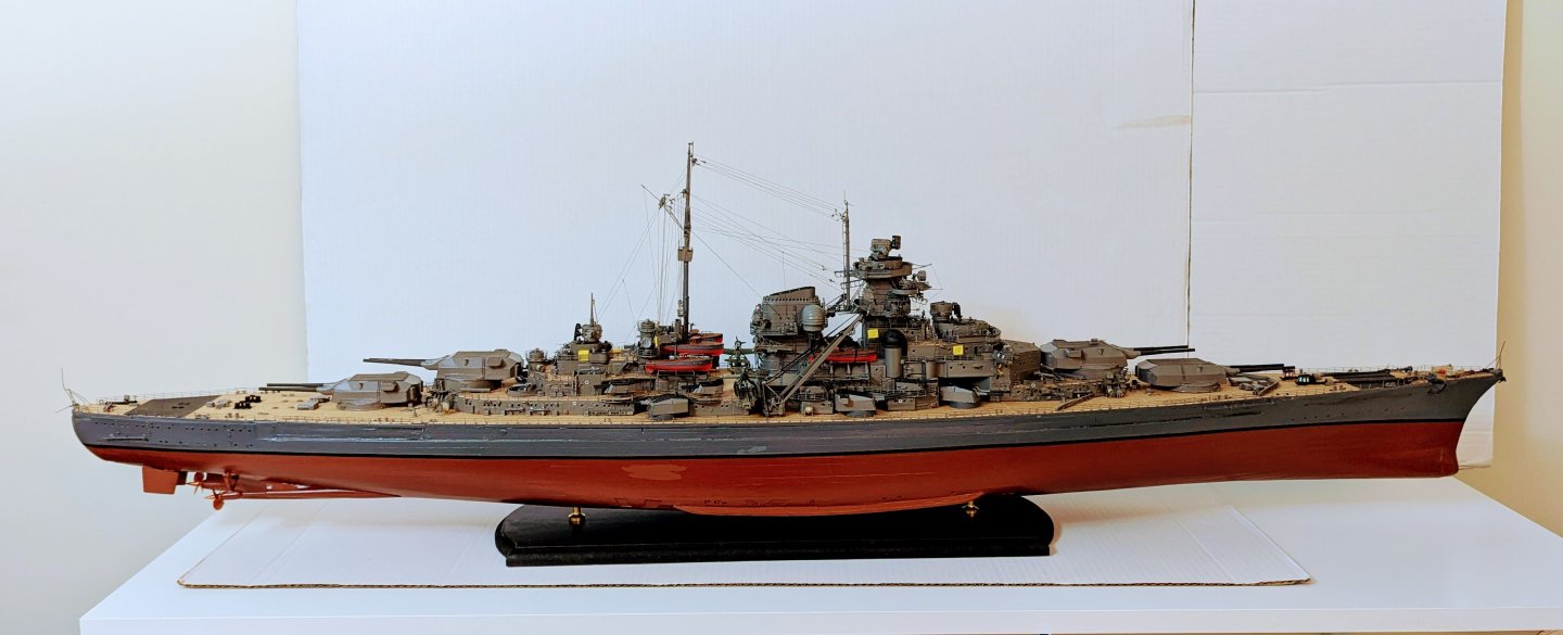
Bismarck is FINISHED! Elapsed time for this one was one year three months. I've posted one full picture of the model here, but I have also posted an album of completion pics in the Gallery. [See post that follows if you want to follow my next build, which isn't a ship, and which therefore has to be done on another site.] Regards, David