HOLIDAY DONATION DRIVE - SUPPORT MSW - DO YOUR PART TO KEEP THIS GREAT FORUM GOING! (Only 36 donations so far out of 49,000 members - C'mon guys!)
×


Gregor
-
Posts
225 -
Joined
-
Last visited
Content Type
Profiles
Forums
Gallery
Events
Everything posted by Gregor
-
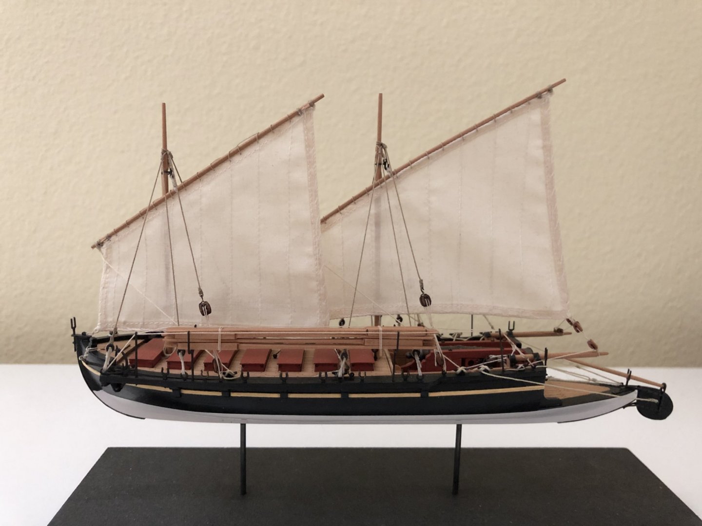
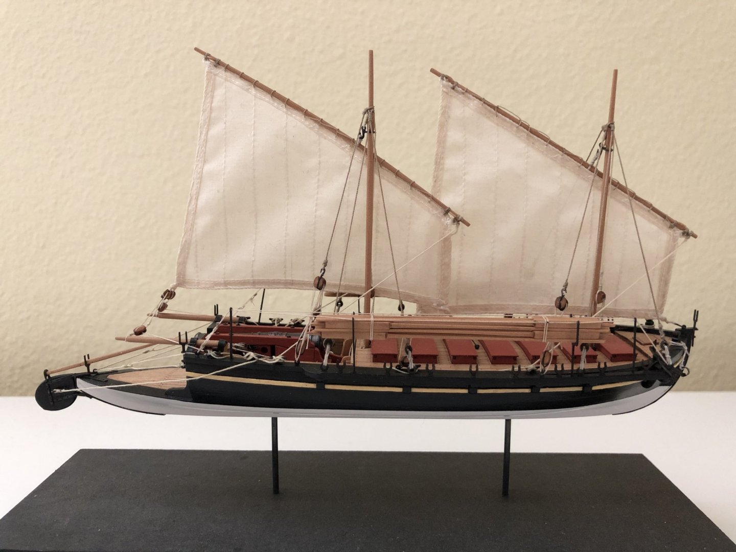
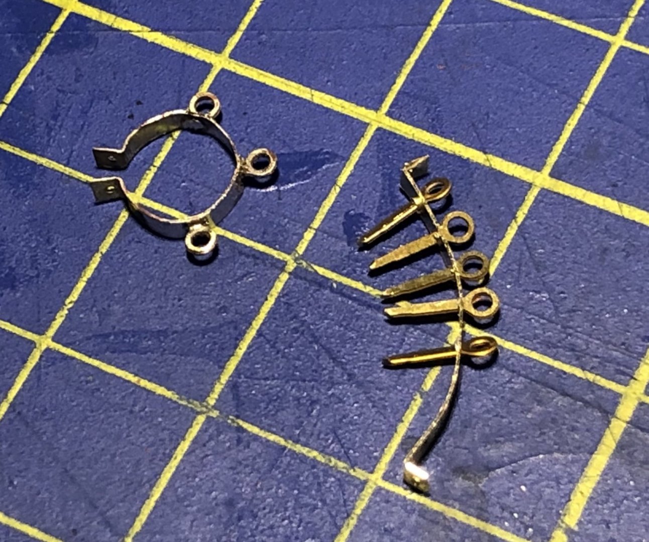
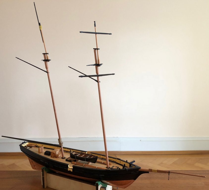
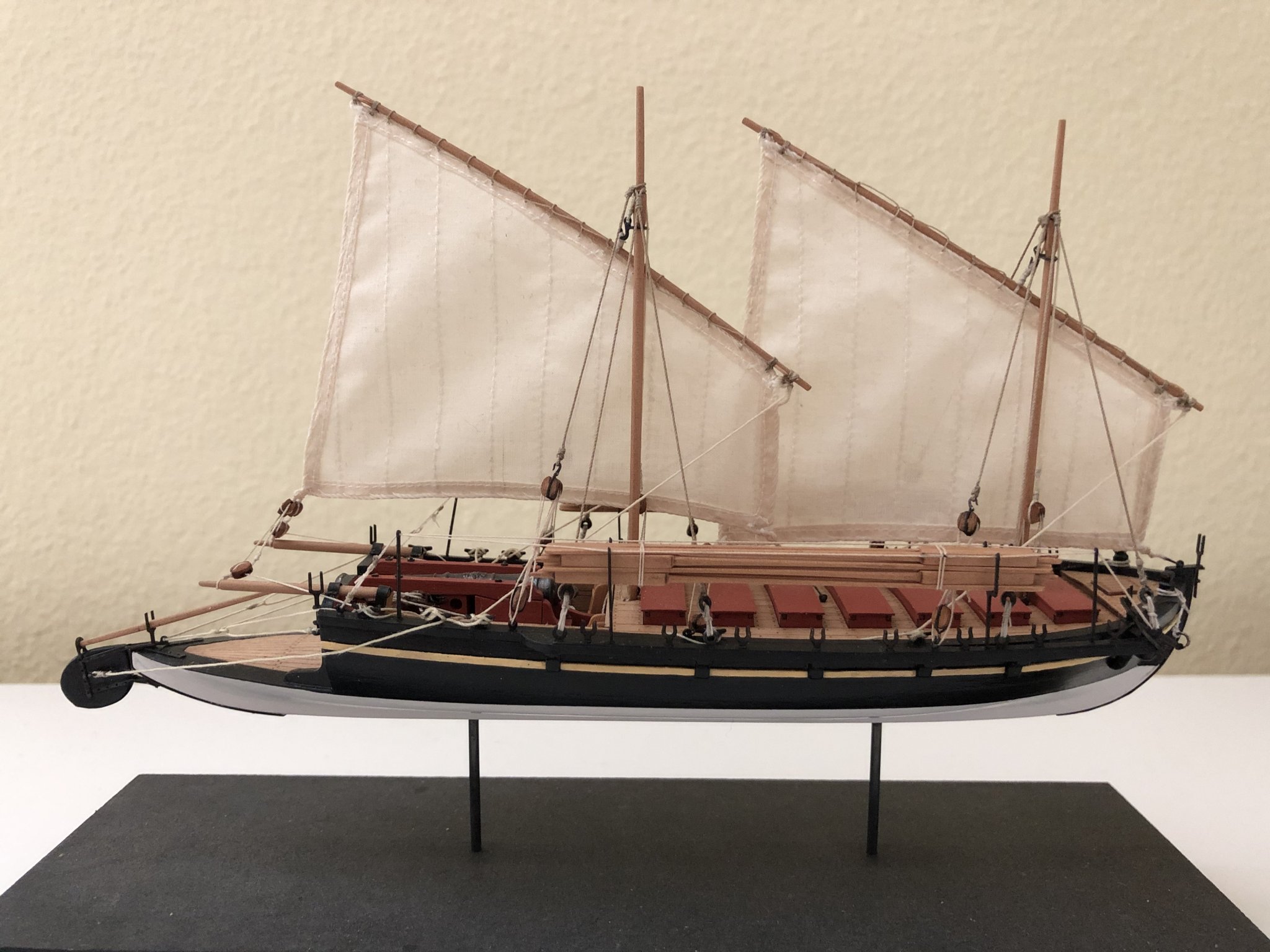
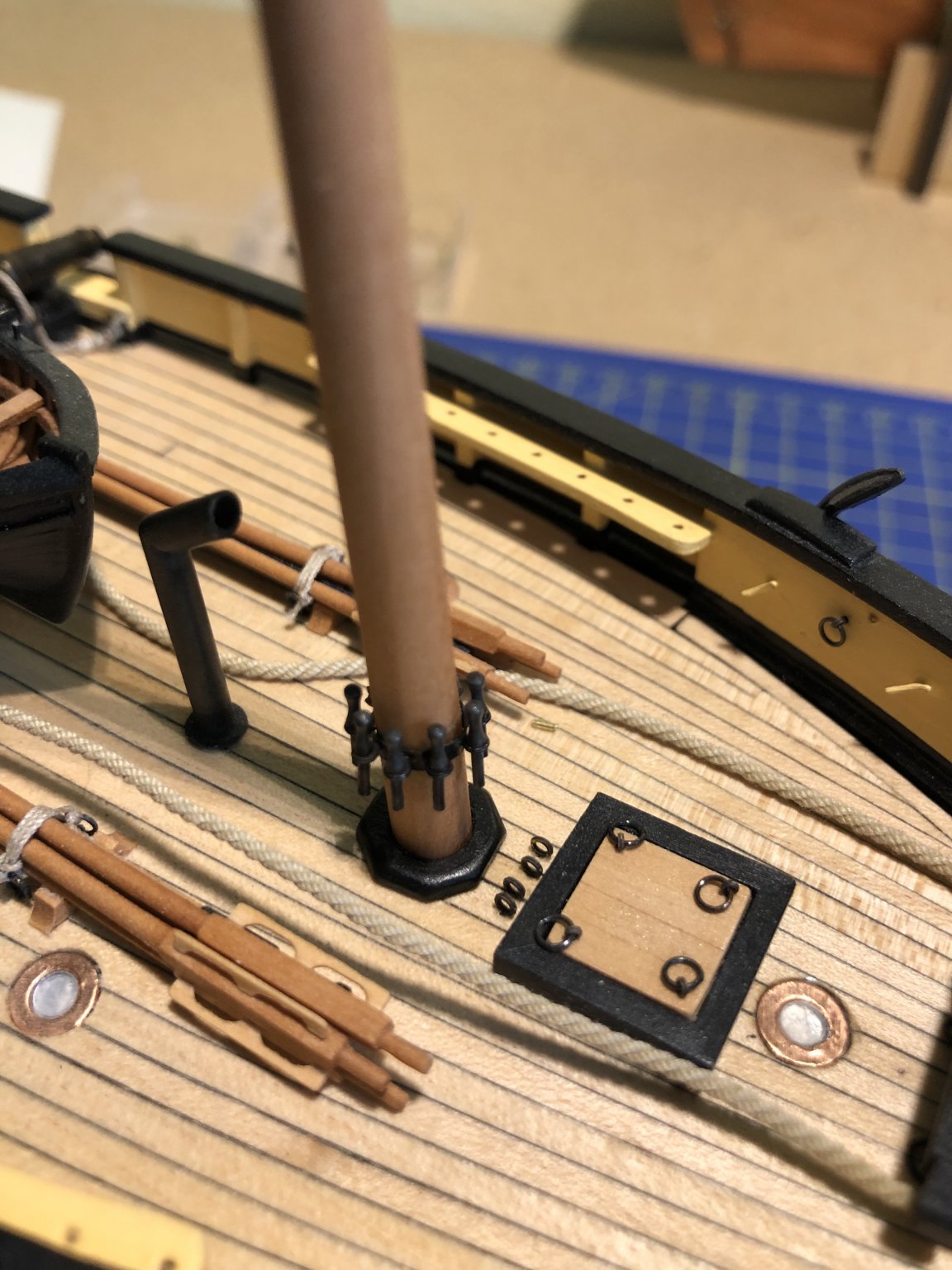
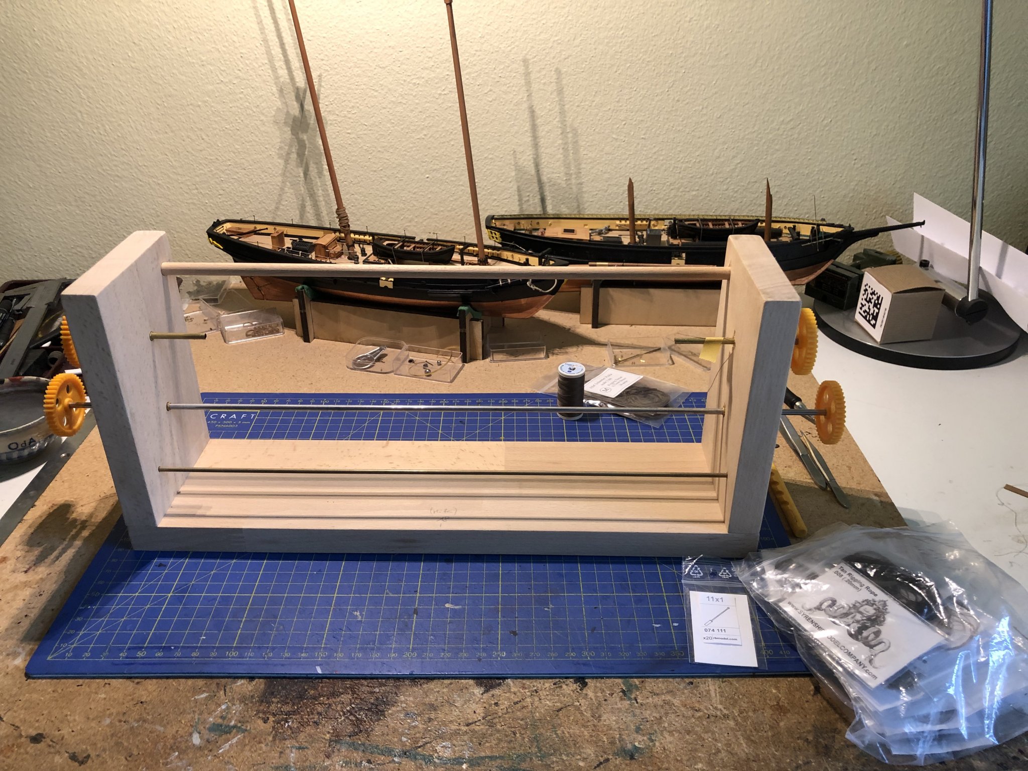
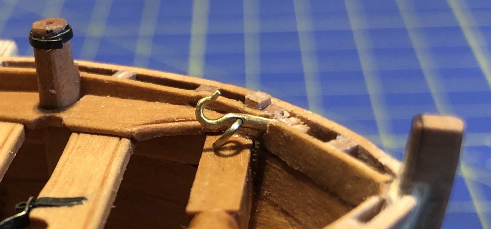
In the last few months my home office has taken up more space. During this time, I pursued another small project: A gunboat from 1801, a Swedish-Russian design (A.F. Chapman), a kit from Master Korabel in 1/72nd scale. But finally, I will begin the rigging of La Topaze. Some details were still missing: The rings for the belaying pins around the masts (they measure 6 mm in dameter), and the railing supports. Now I’m out of excuses. My old serving machine was dusted and is ready… Cheers Gregor


- 121 replies
-
- 10
-

-
- la jacinthe
- schooner
- (and 2 more)
-
kit review Kit Review - HMS ENTERPRIZE (1774) by CAF MODELS
Gregor replied to kljang's topic in REVIEWS: Model kits
Hi Jeff In 1:48 the hull's length should be 54 cm, in 1:36 then 72 cm (according to Ancre's website: https://ancre.fr/en/monograph/30-monographie-de-la-belle-barque-1680.html#/langue-anglais). I very much hope, Tom, there will be a kit in 1:48. It would be a unique opportunity to build a fully framed model of a small ship in a relatively small scale. I'm hoping and looking very much forward to this kit. Cheers, Gregor -
kit review Kit Review - HMS ENTERPRIZE (1774) by CAF MODELS
Gregor replied to kljang's topic in REVIEWS: Model kits
Thanks for this review - I'm eagerly waiting for the reappearance of the La Belle kit, as I just bought Ancre's monography from another modeler. I had to give up space for Homeoffice, so HMS Enterprize is simply too big for me. What I really admire here is the clever kit-design, excellent for people like me with more romantic dreams than useful modeling skills. I wish Tom total success with his enterprise, may there be soon an agreement! Gregor -
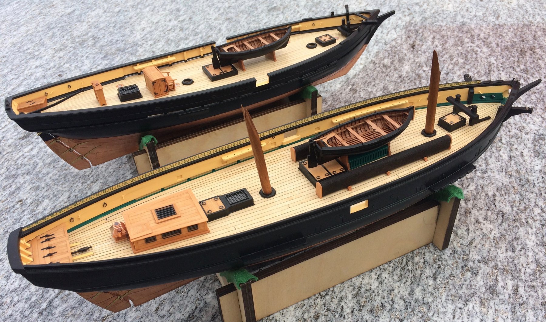
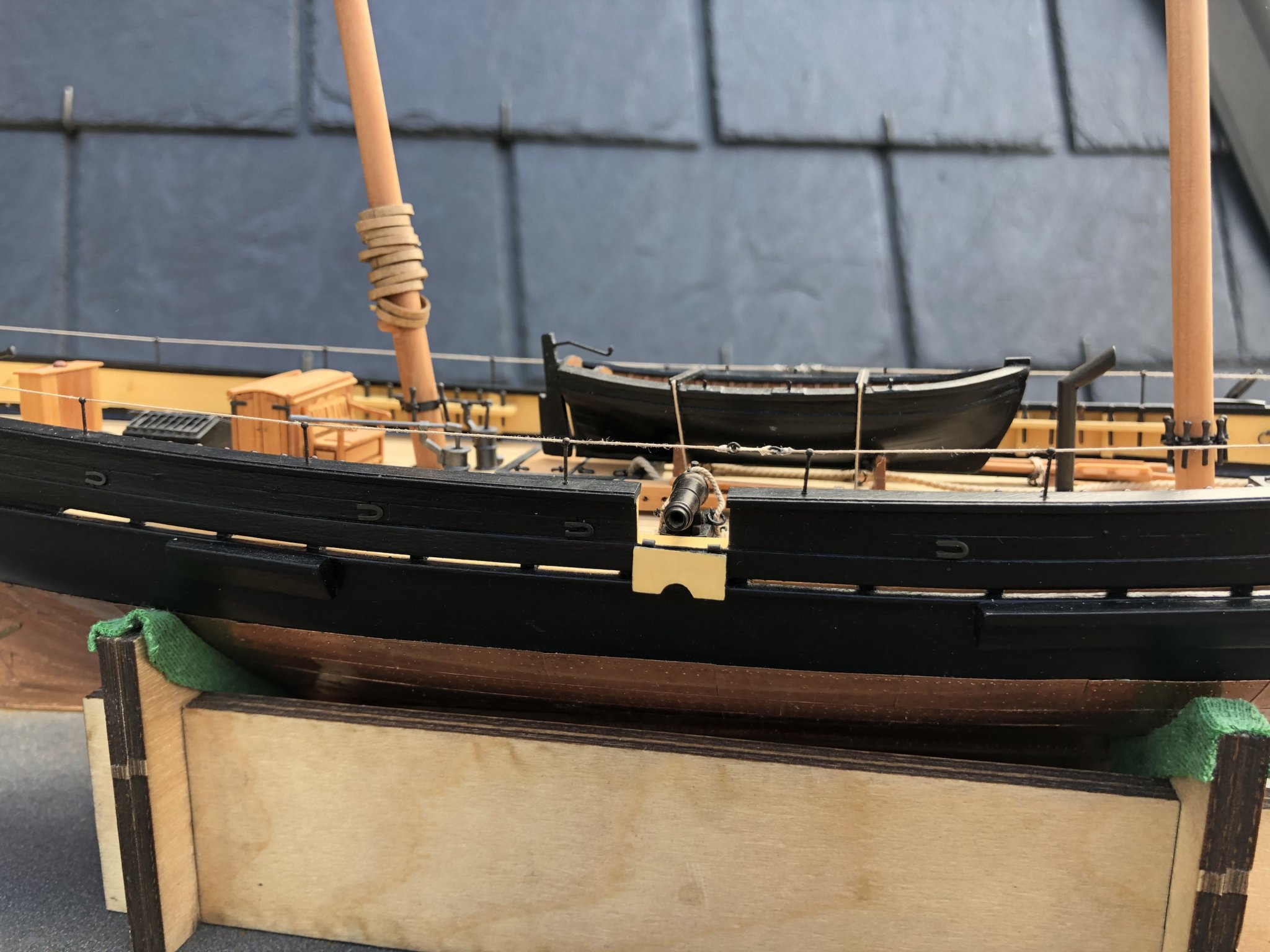
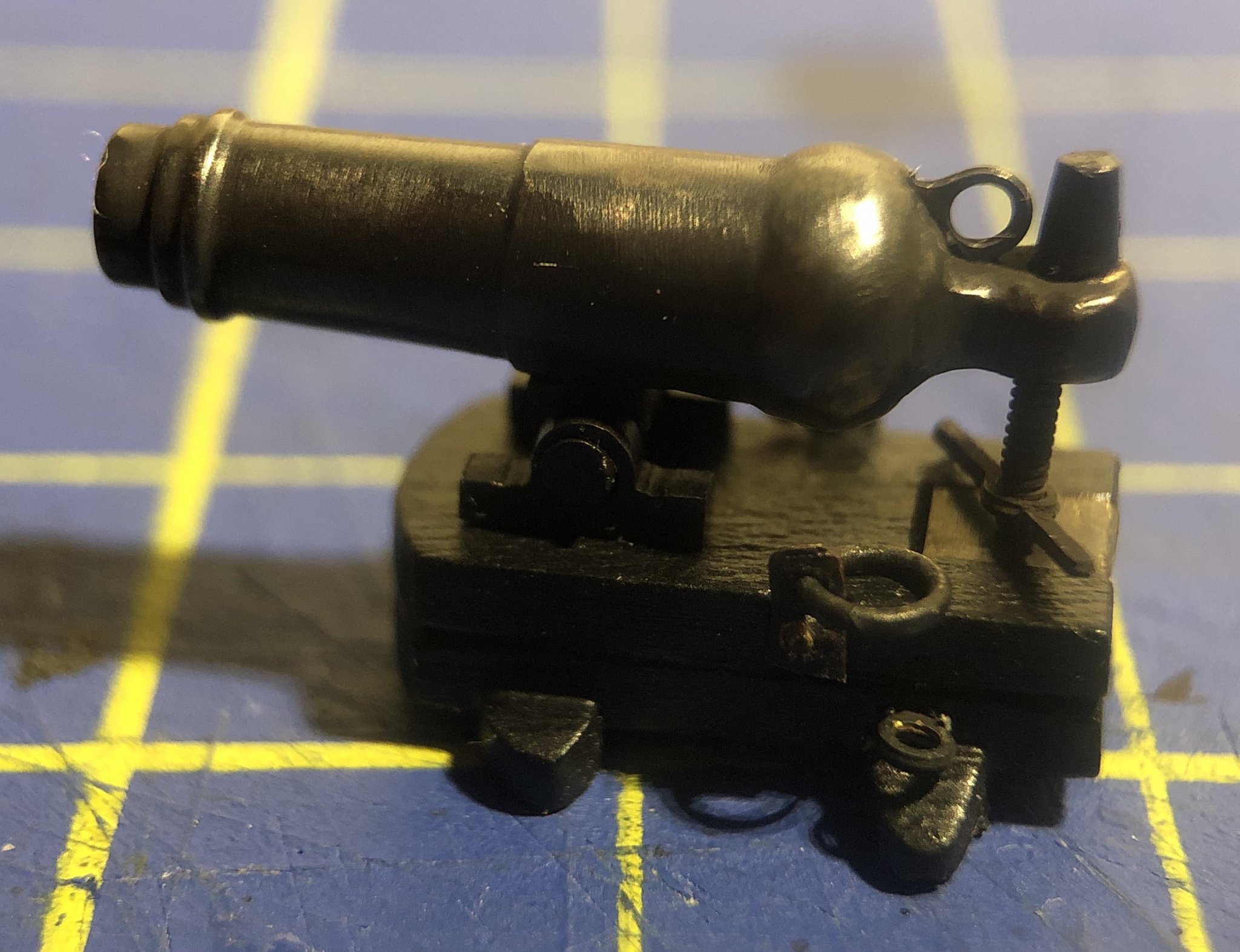
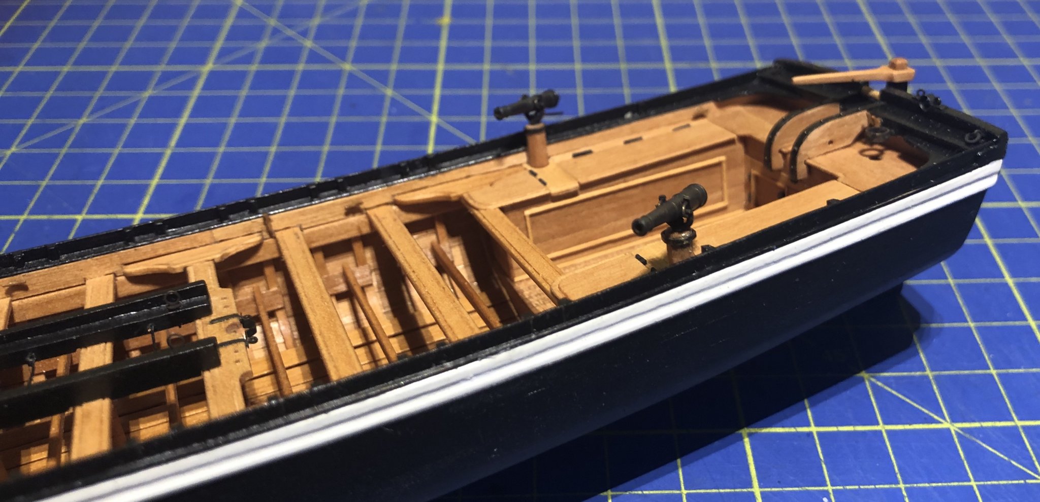
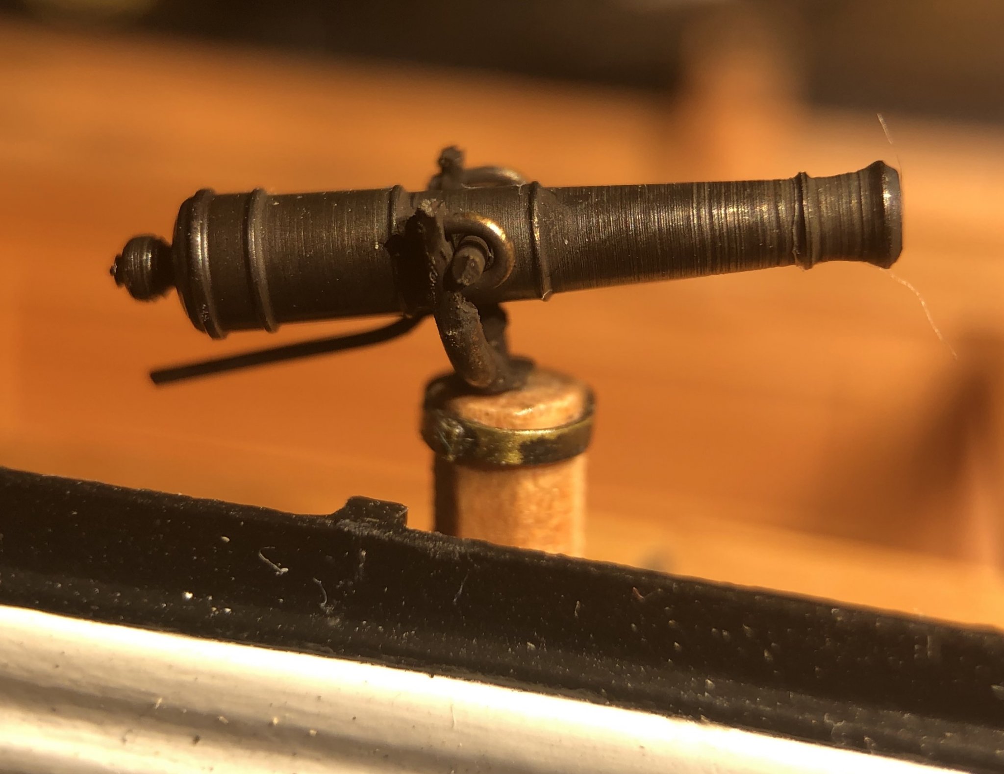
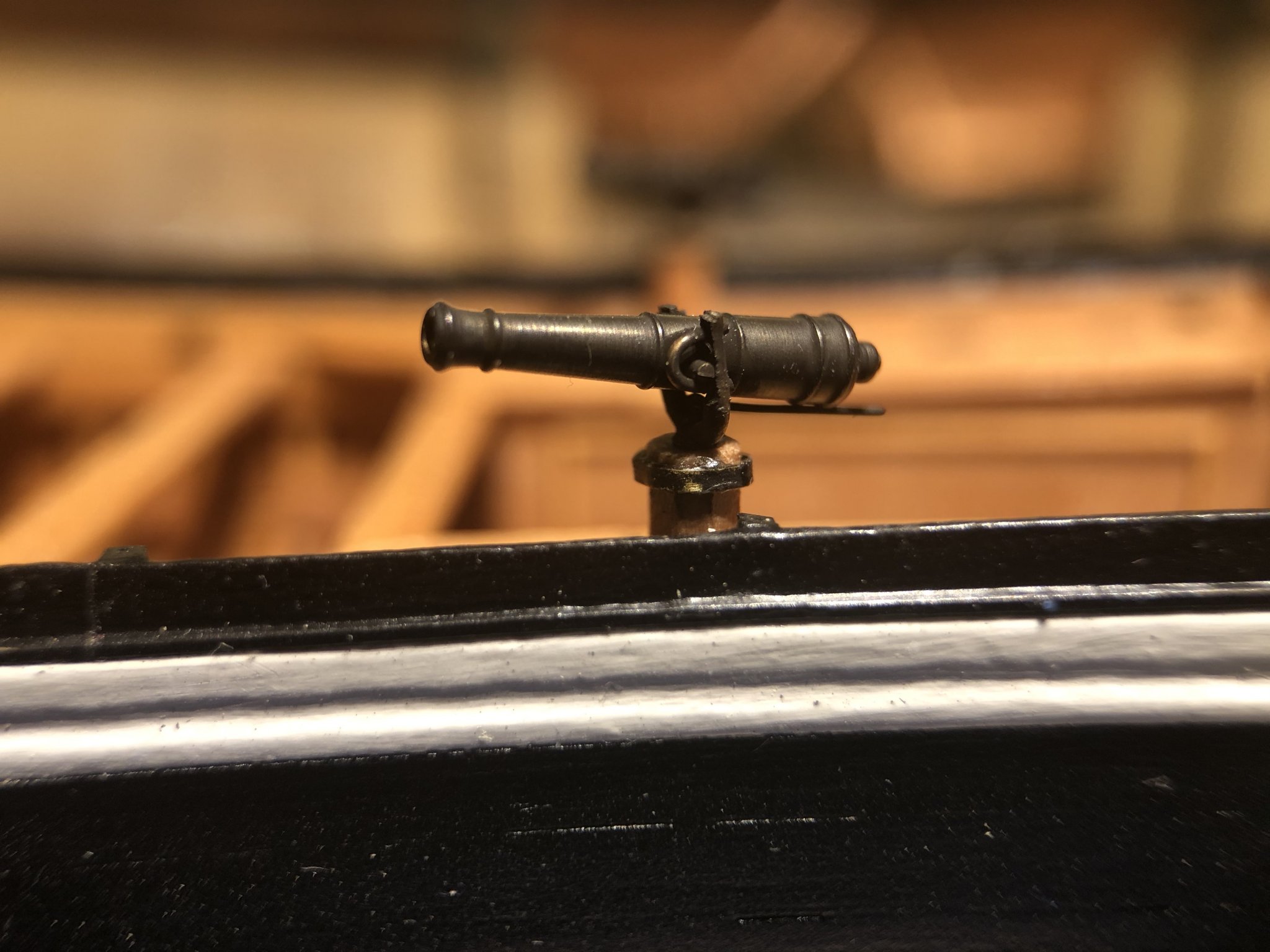
Finally, a small update: Both pairs of carronades are installed. Each is about 20 mm long. Here on the deck of La Mutine... ... and on the deck of La Topaze. Have a nice weekend, Gregor


- 121 replies
-
- 17
-
-
- la jacinthe
- schooner
- (and 2 more)
-
Thanks, Tony, you are very kind. And no, the base is simply black MDF, and two pieces of blackened brass rods - it's not in naval style of dark wood and shiny metal, but I like the simplicity. And next? My two schooners are finally getting armed and should be rigged someday... (and there is the lure of a Swedish gun boat, still in its box from Master Korabel - a gift to myself and a souvenir of last summer's travels there). Gregor
-
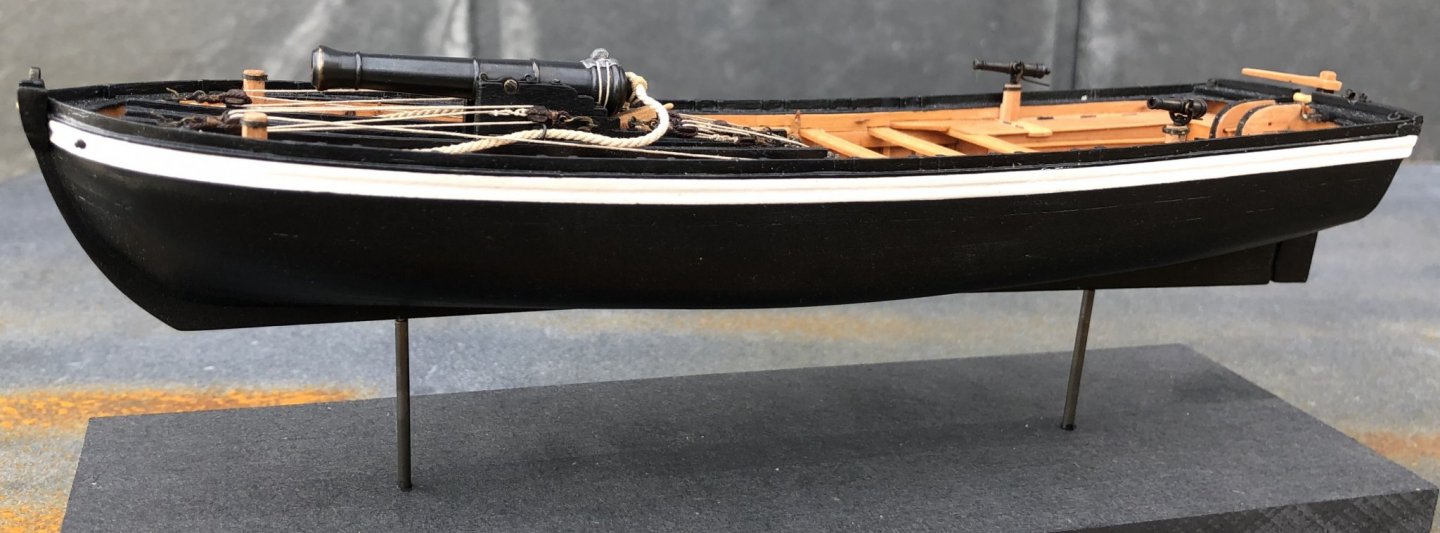
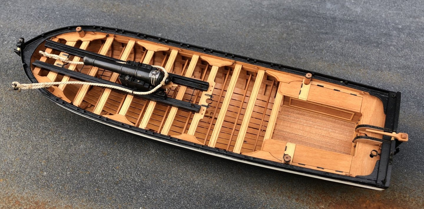
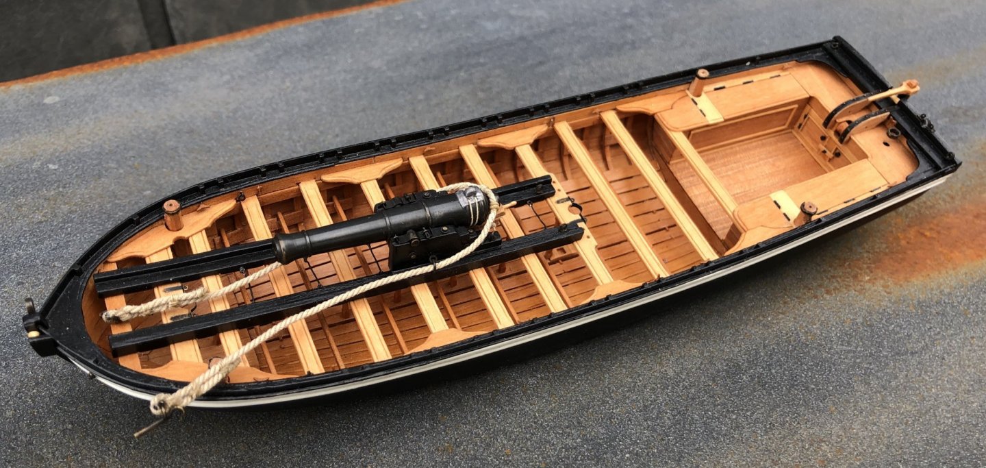
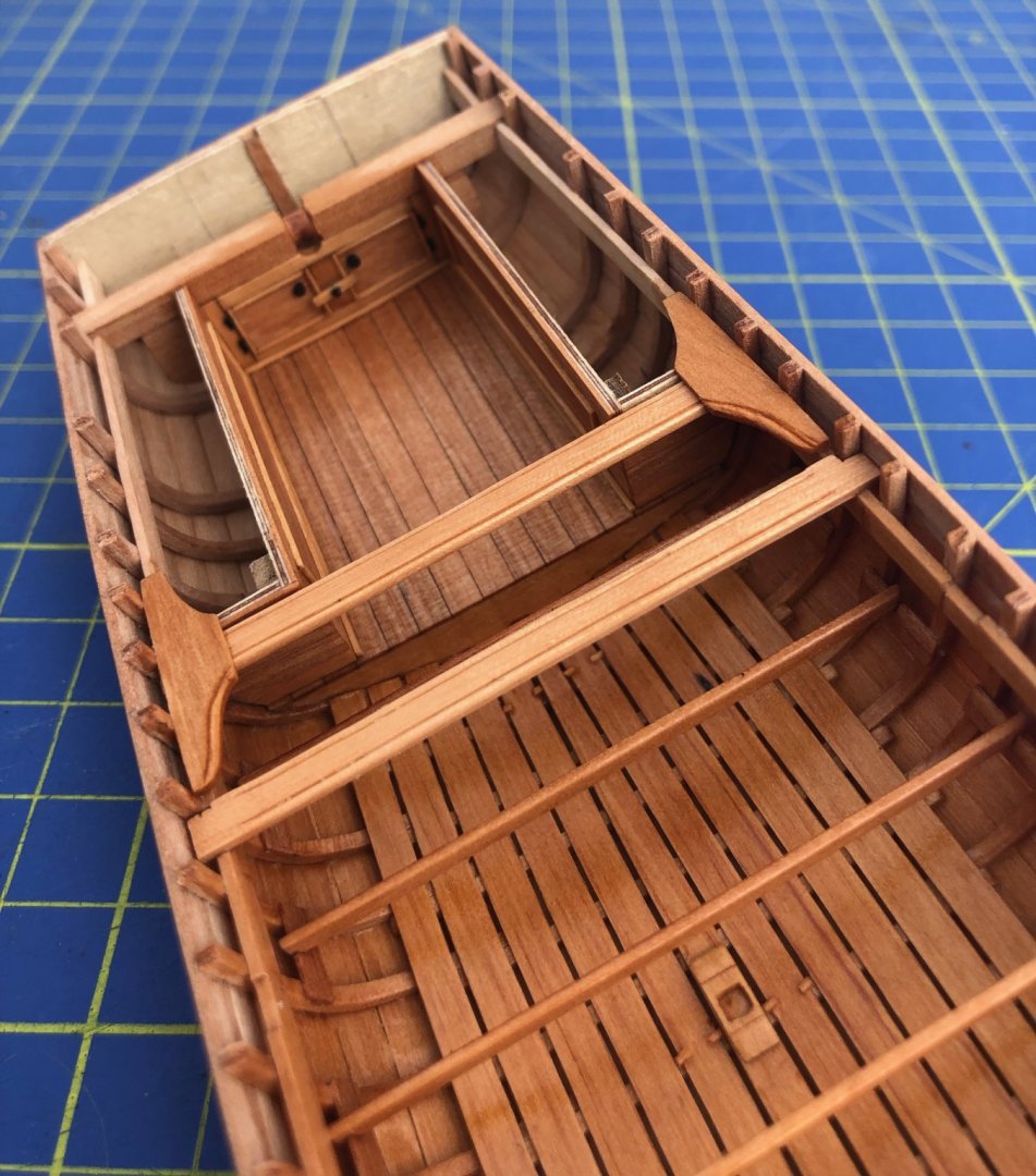
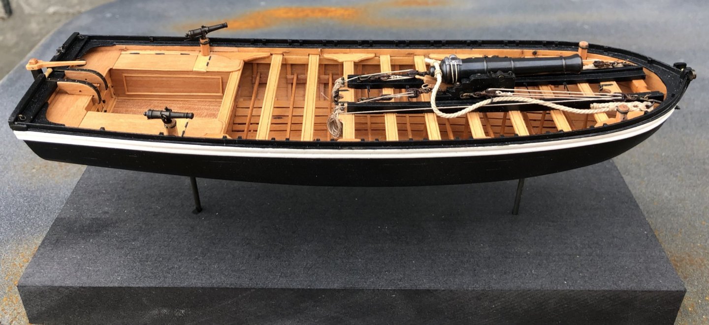
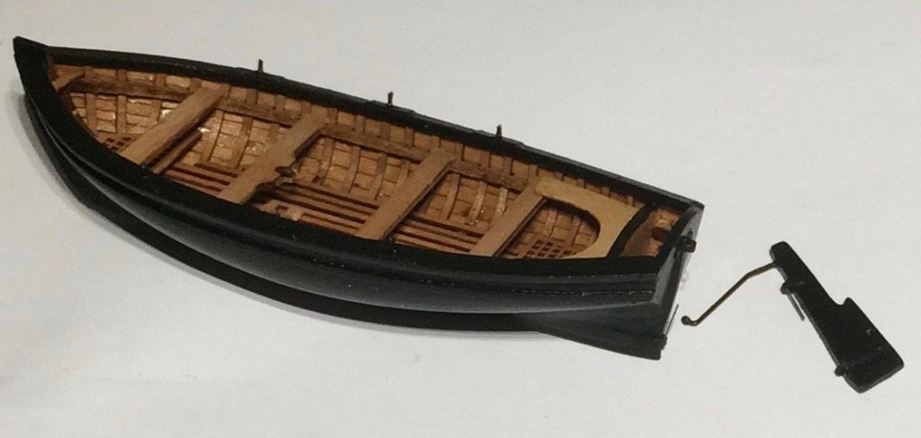
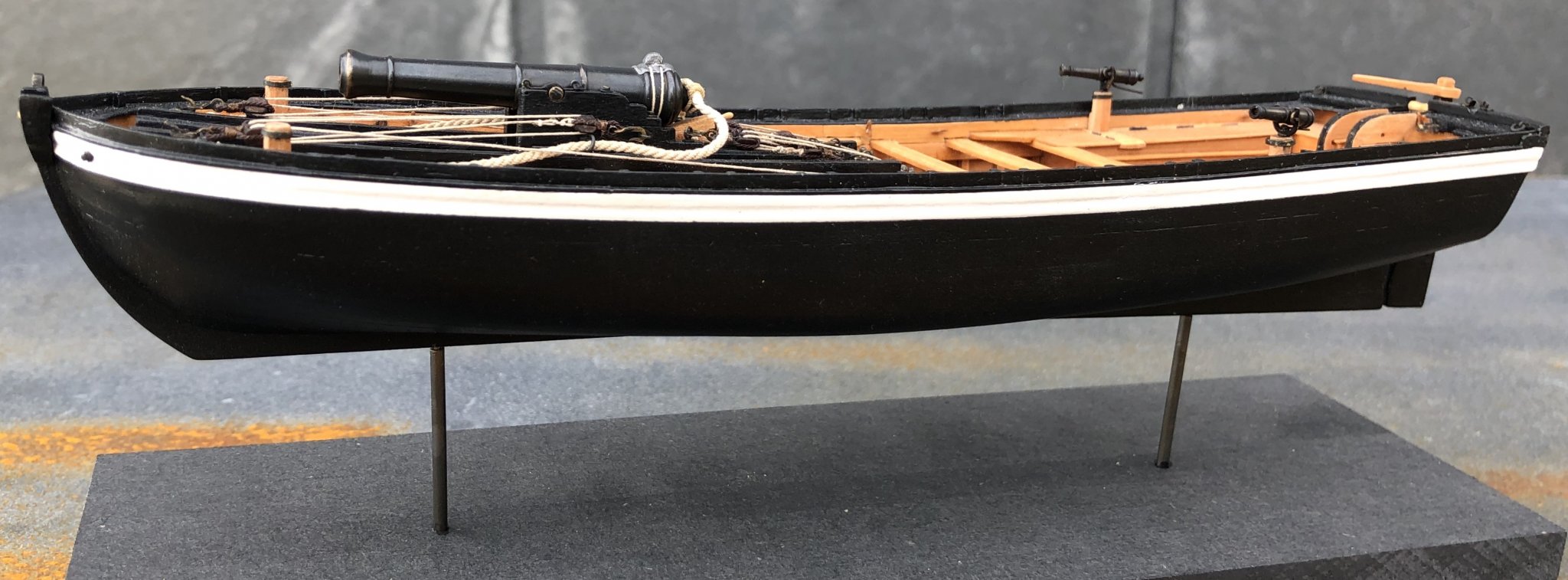
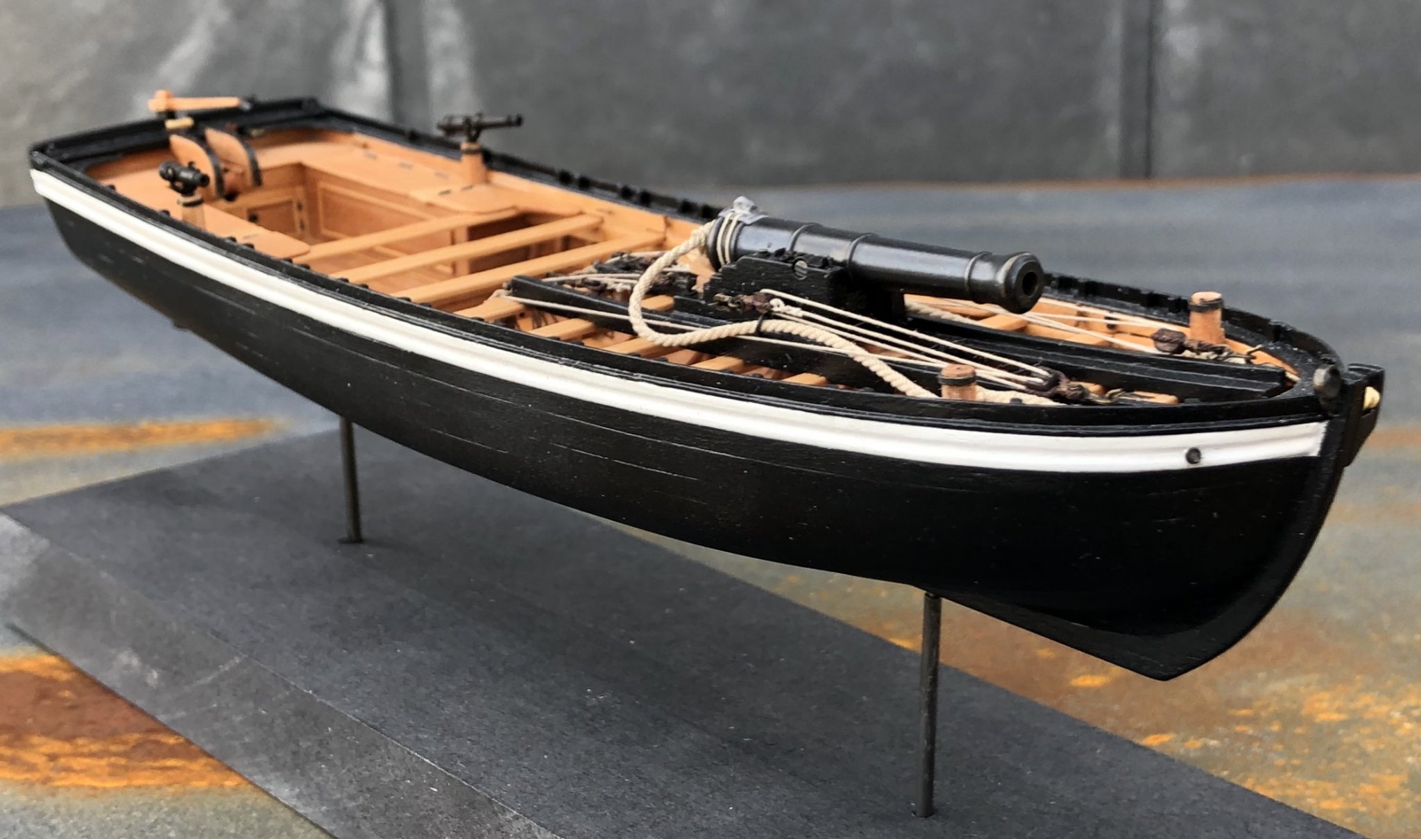
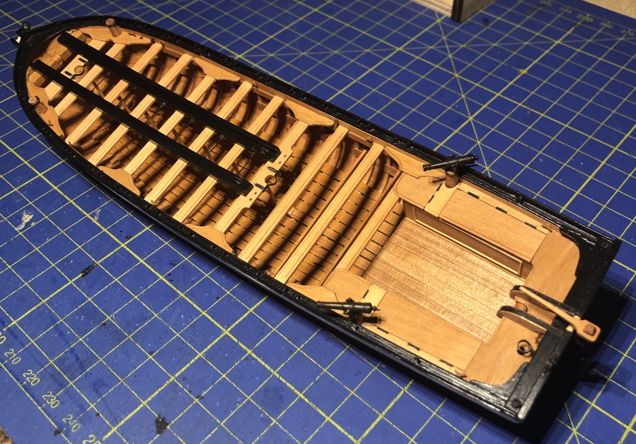
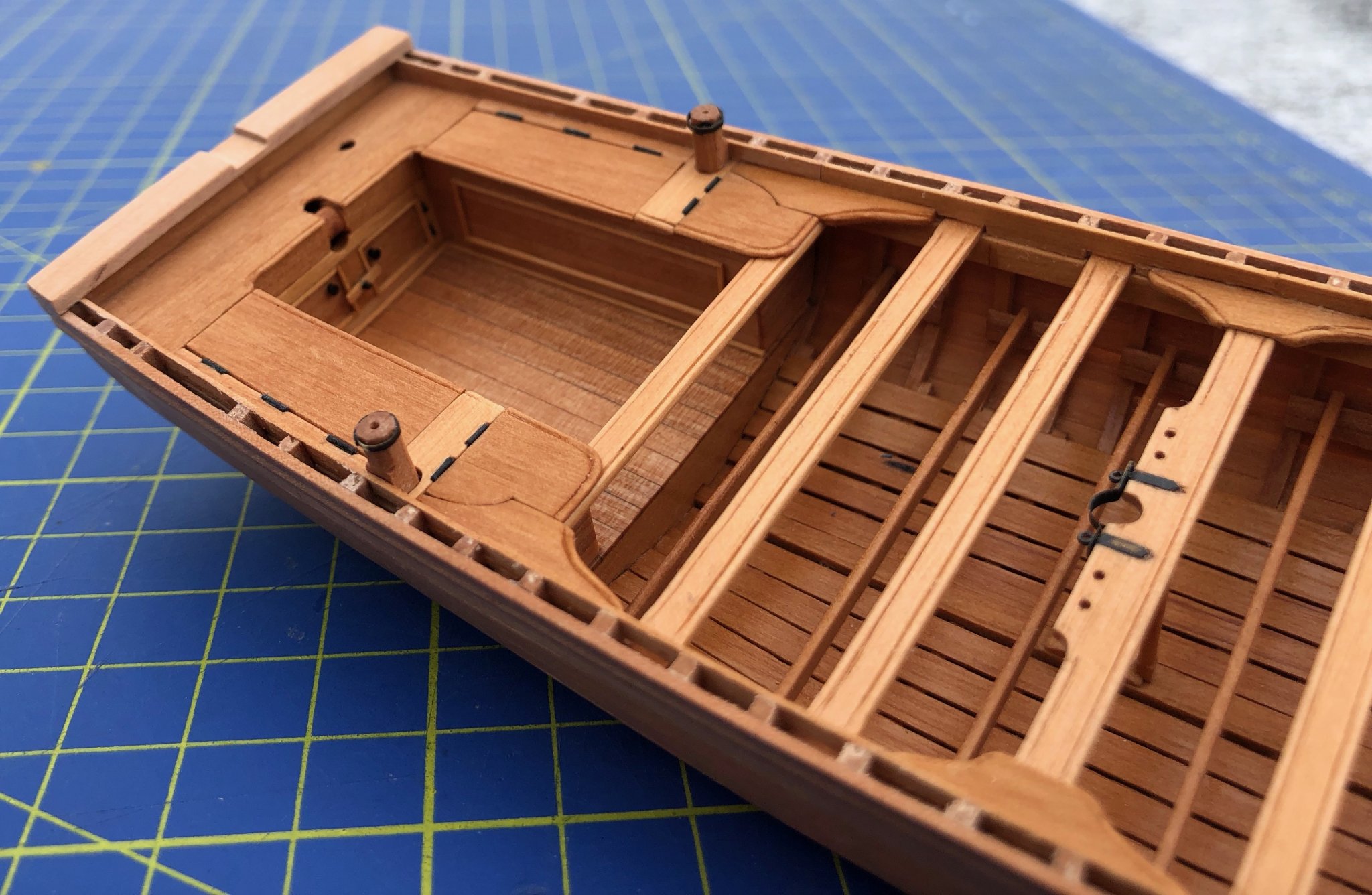
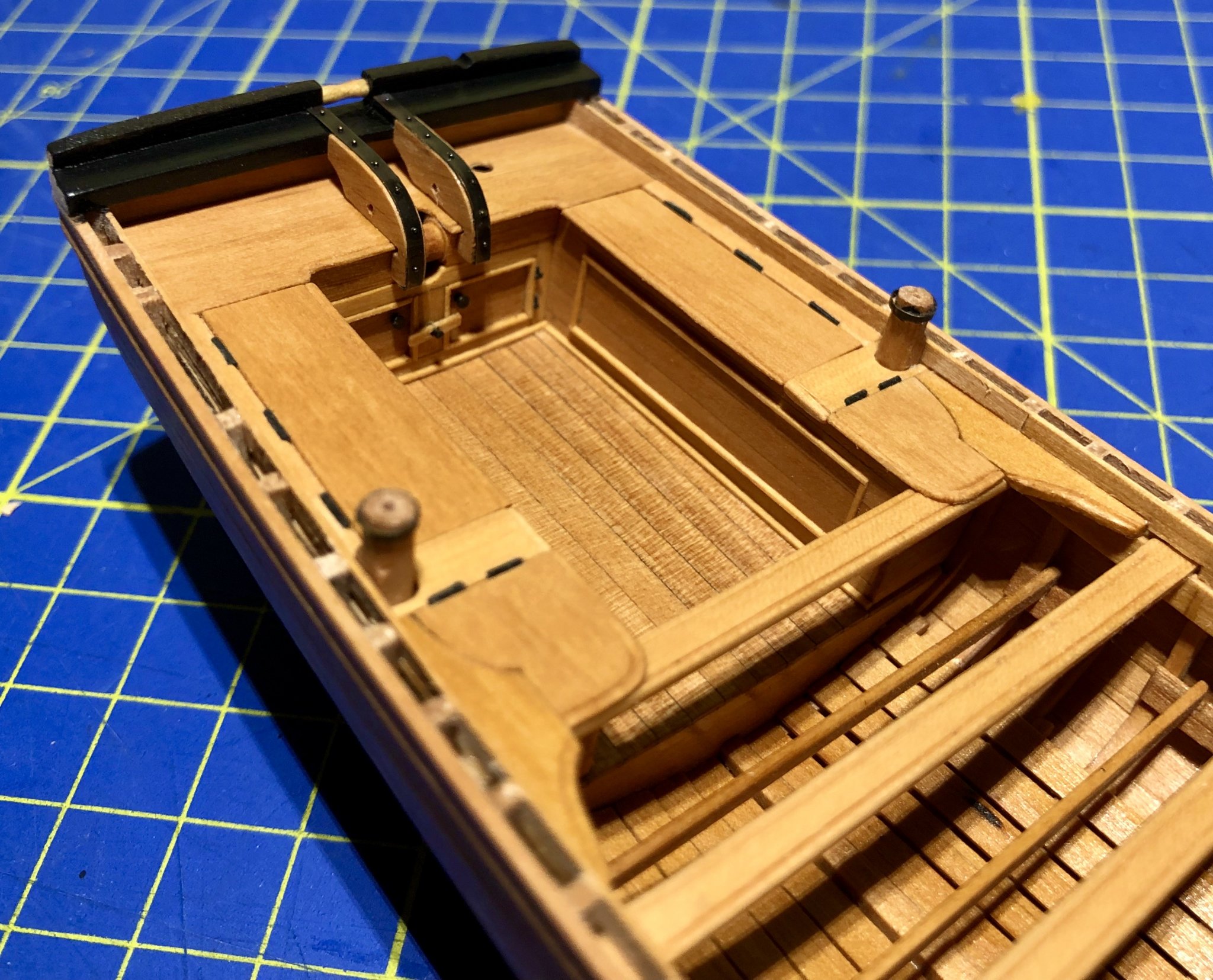
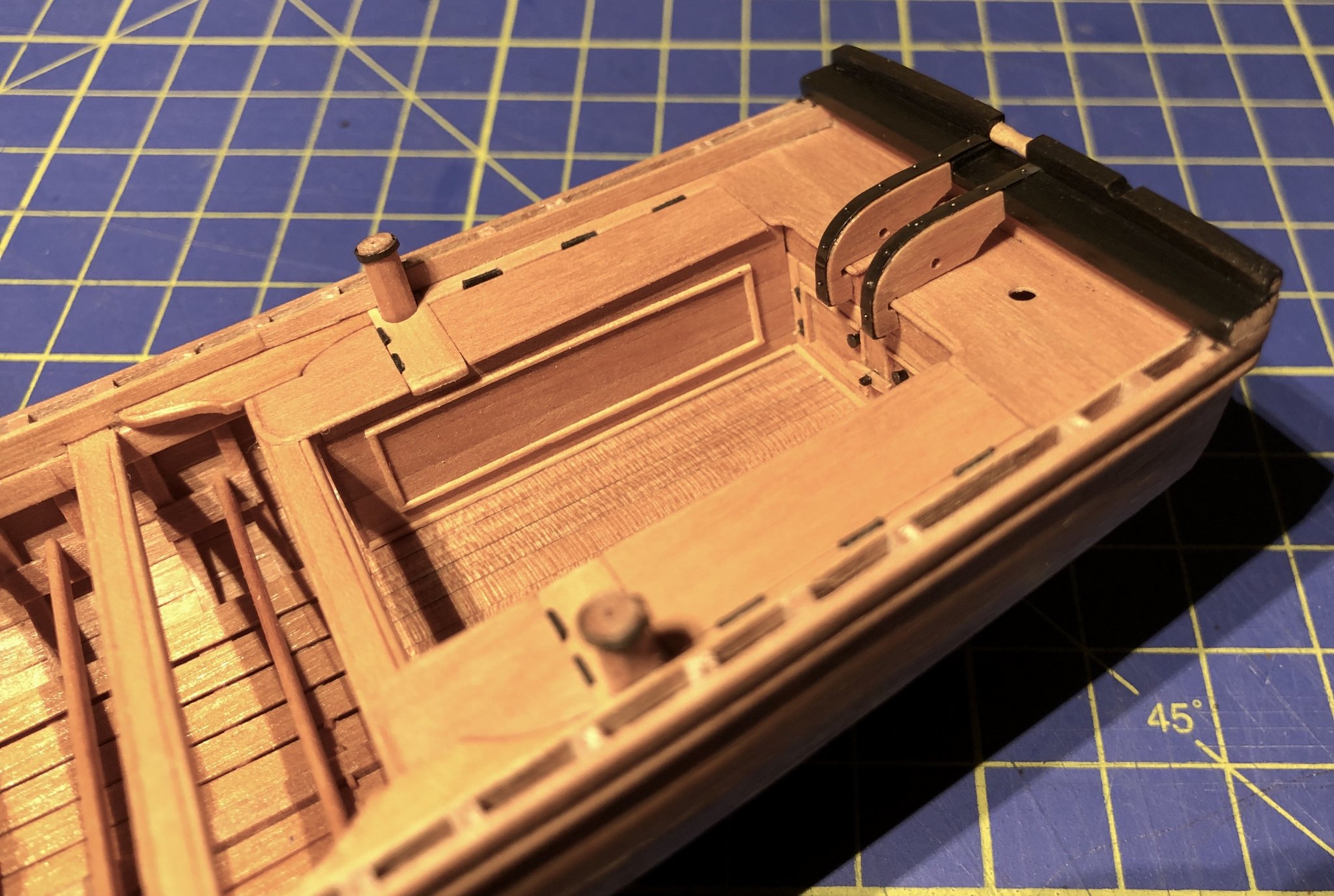
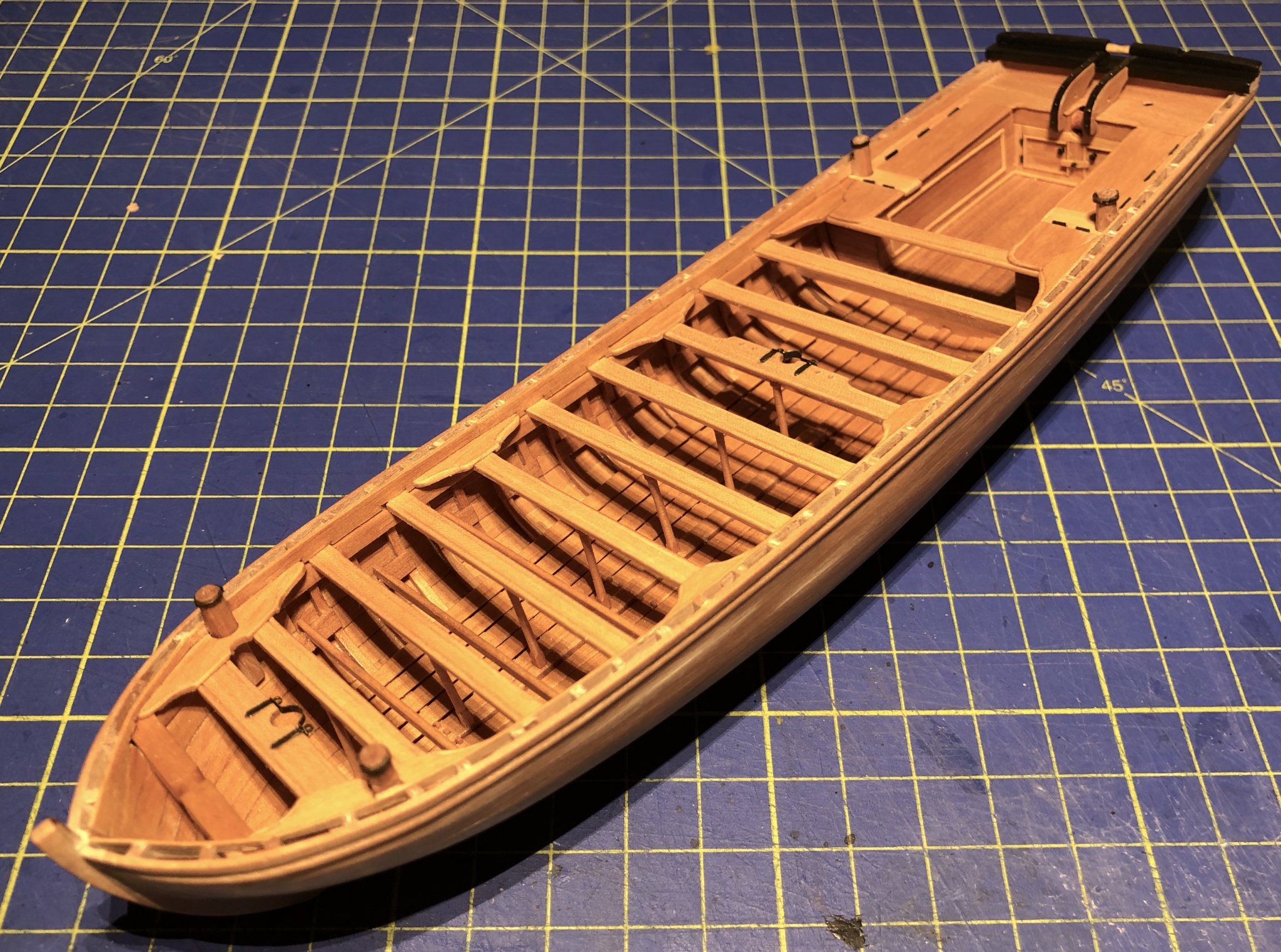
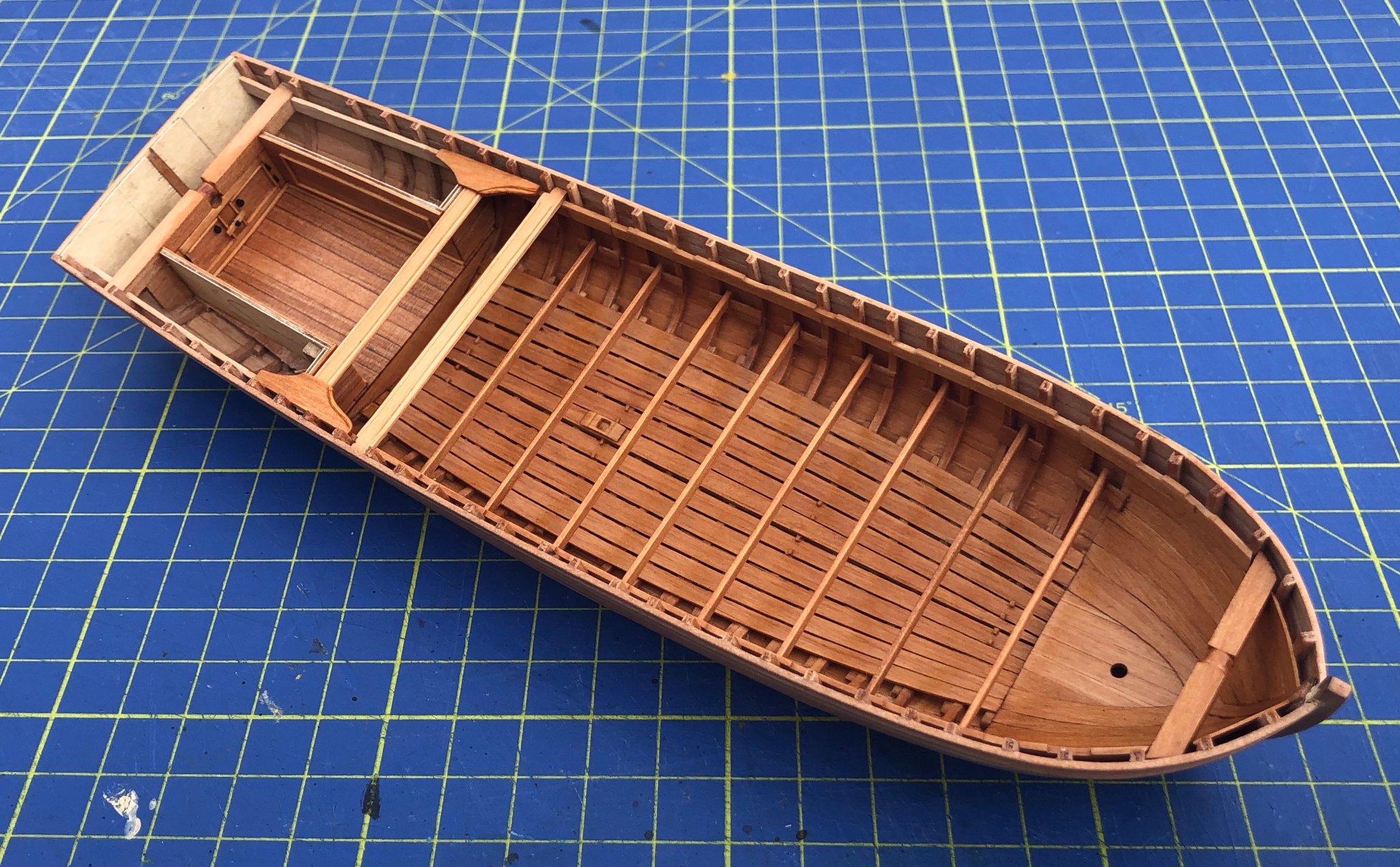
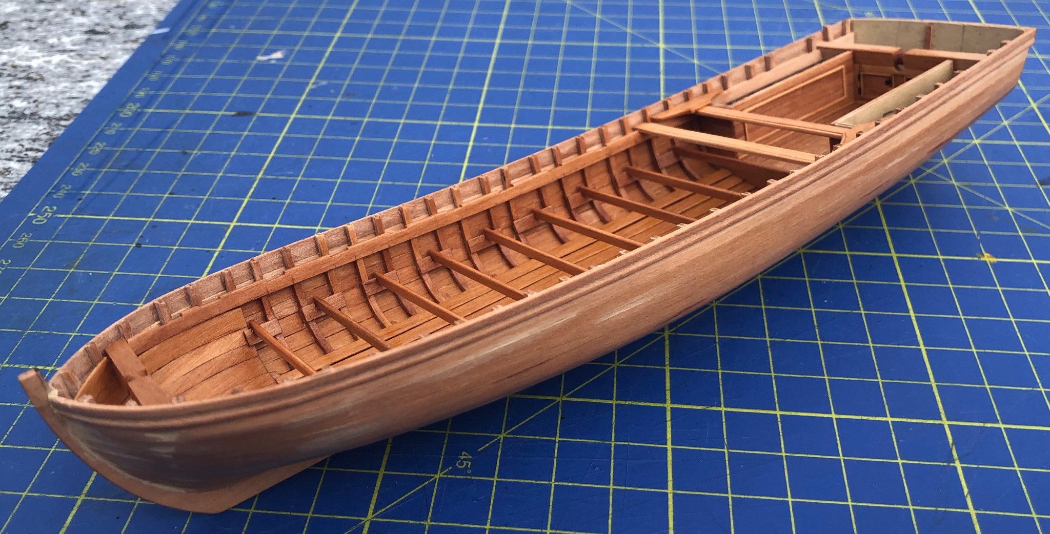
Here is the finished boat, with a few more details. I really can recommend Gérard Delacroix's plans, and I hope to motivate a few of you to buy them and build your own. Cheers, Gregor.


- 15 replies
-
- 17
-
-

-
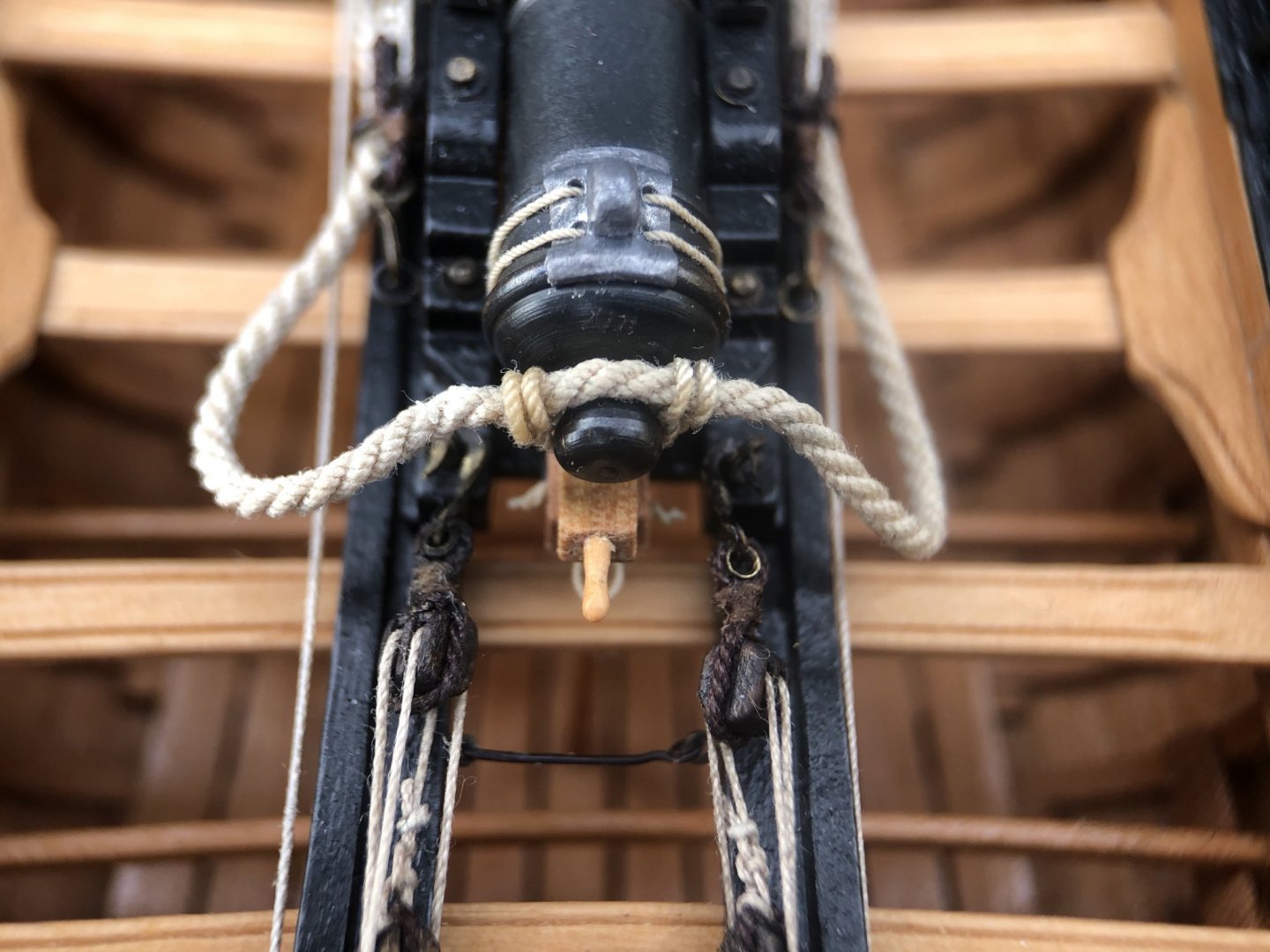
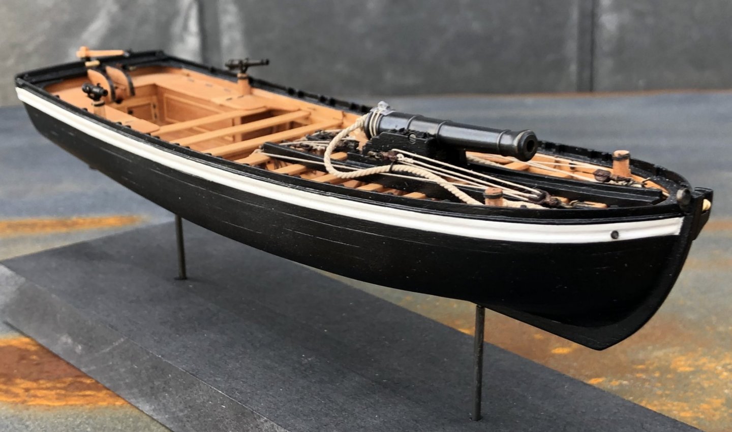
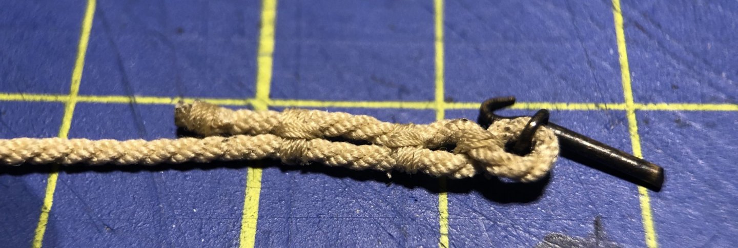
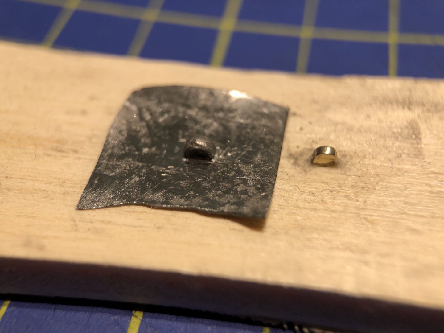
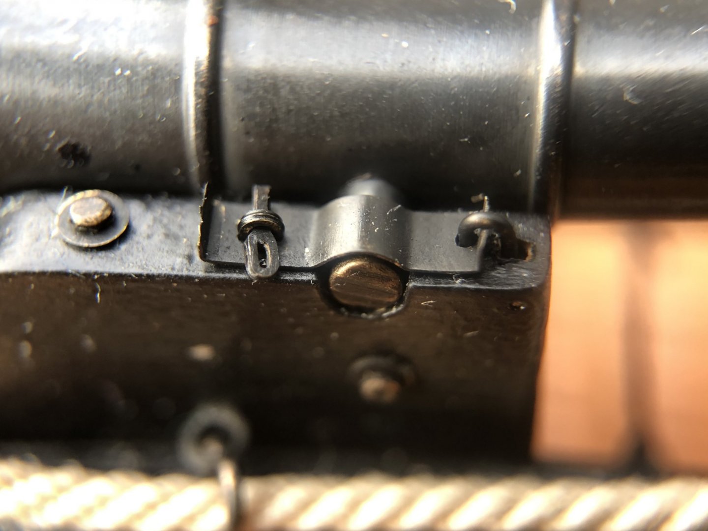
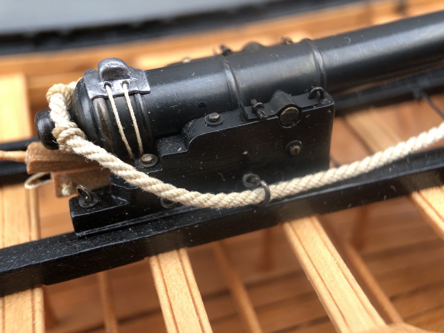
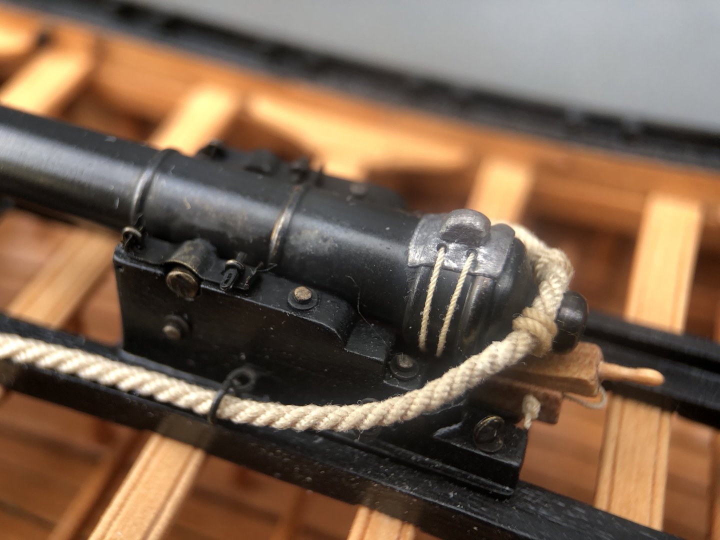
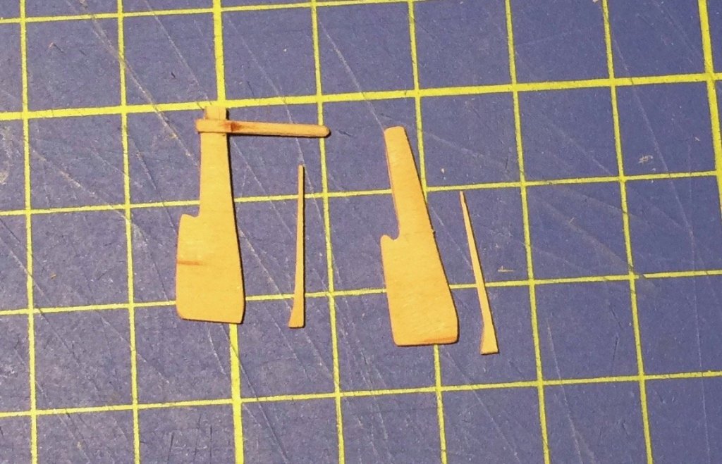
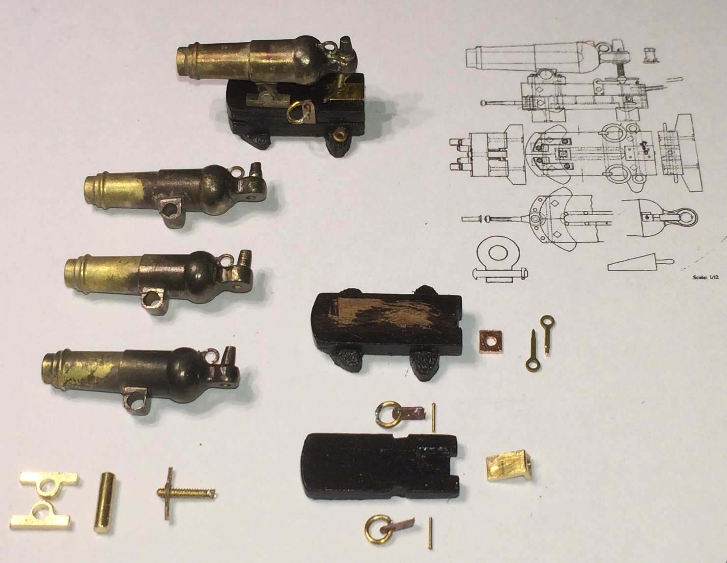
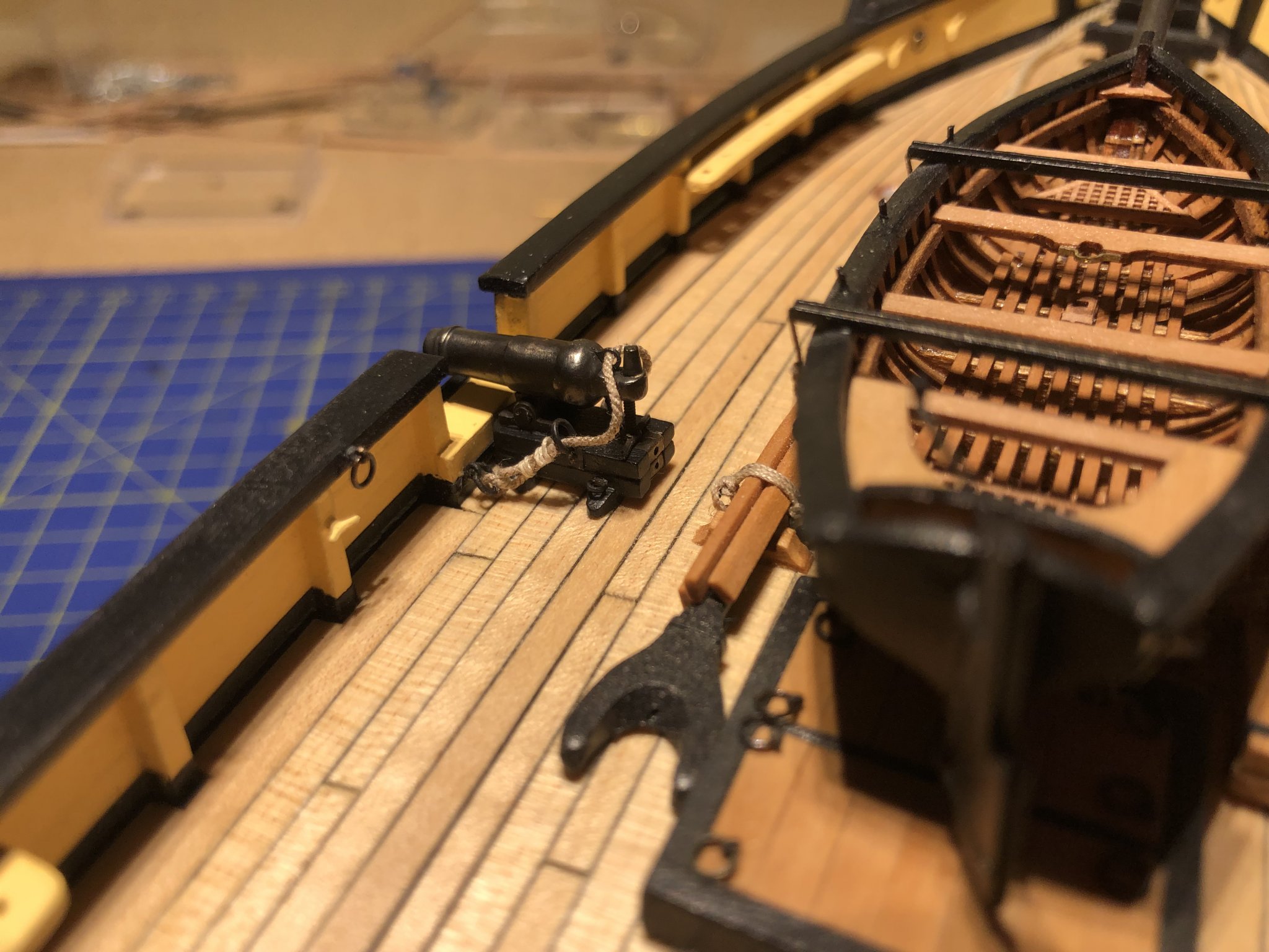
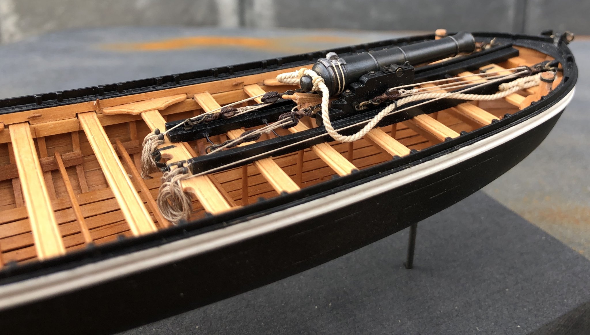
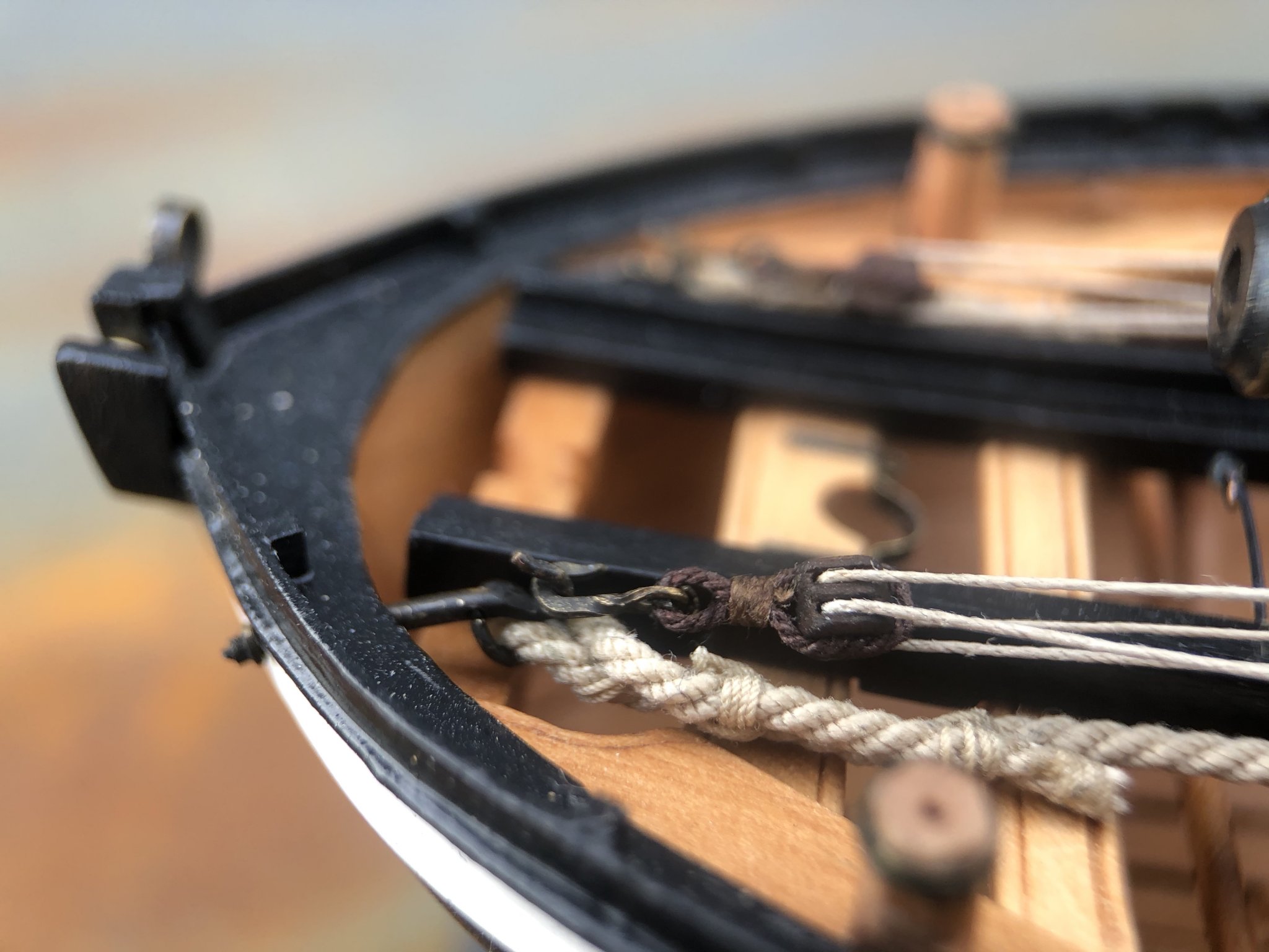
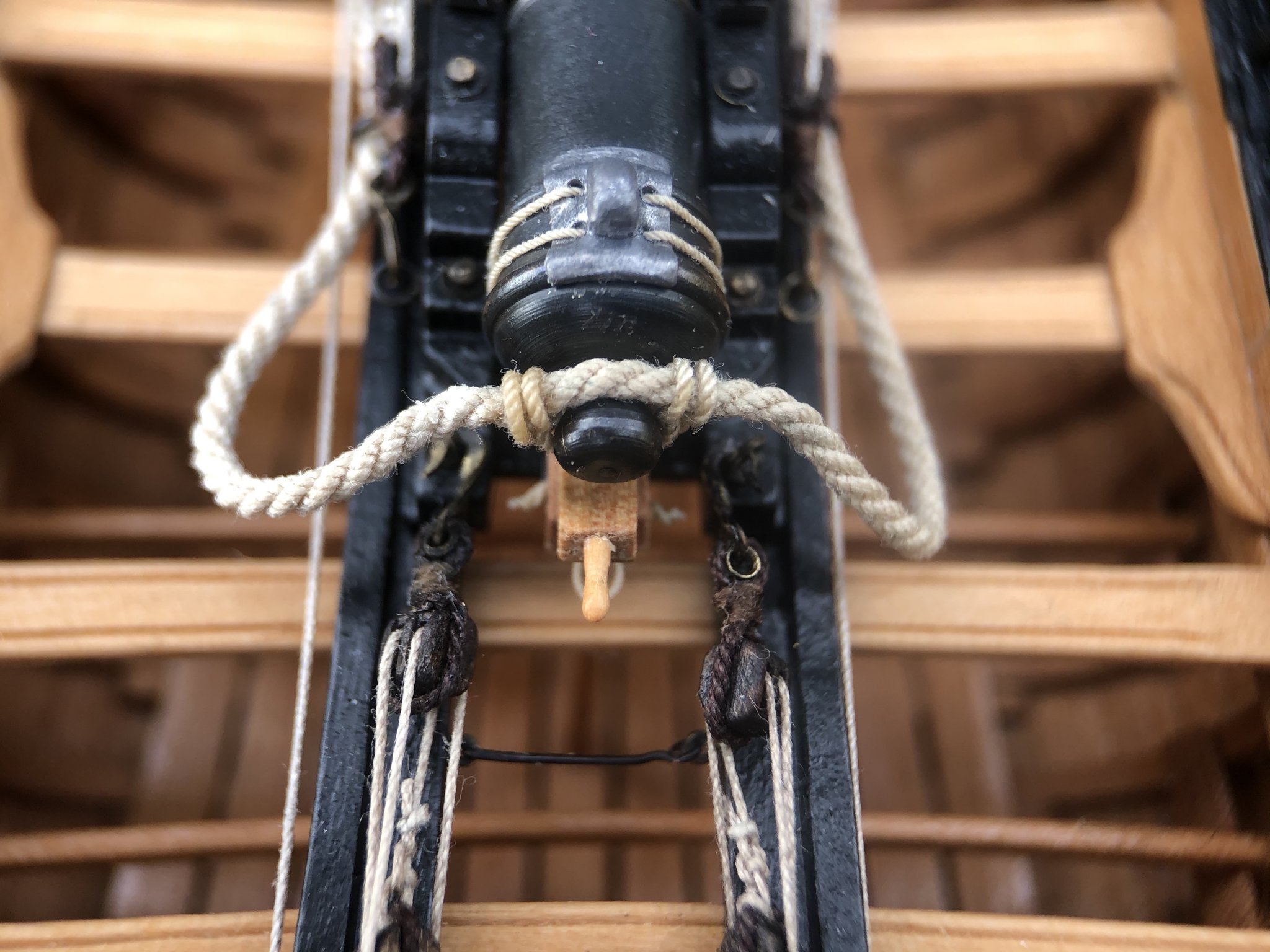
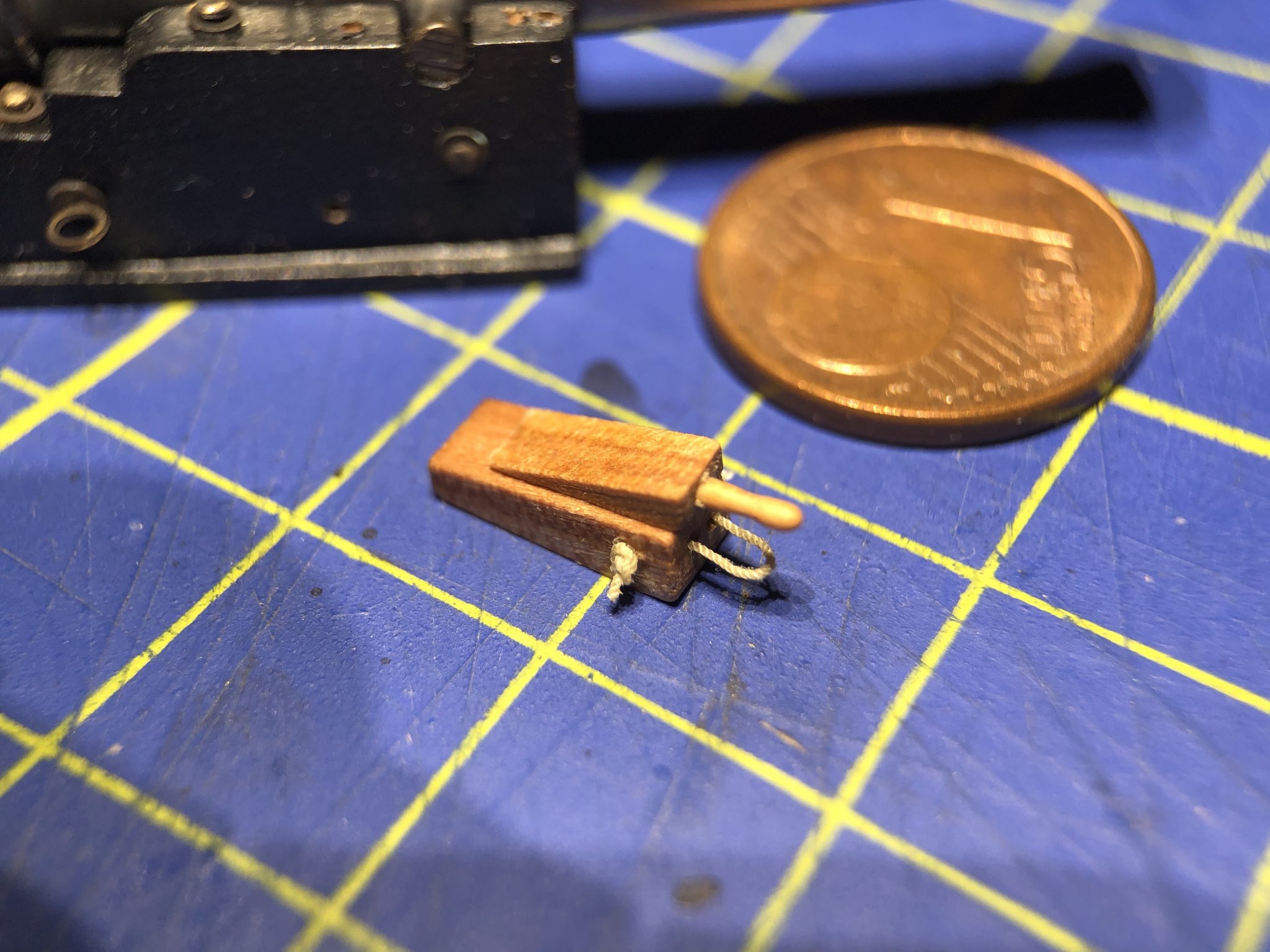
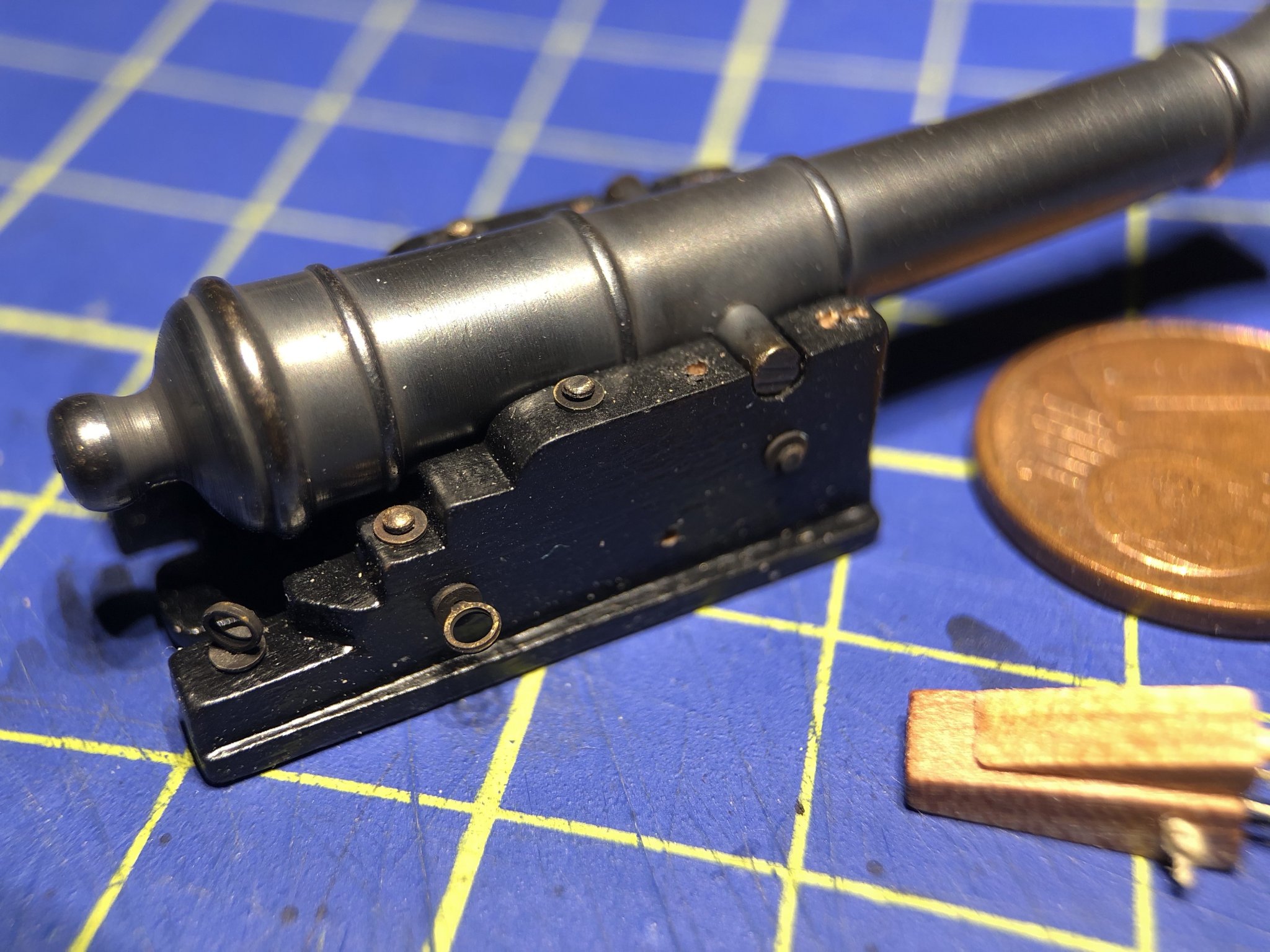
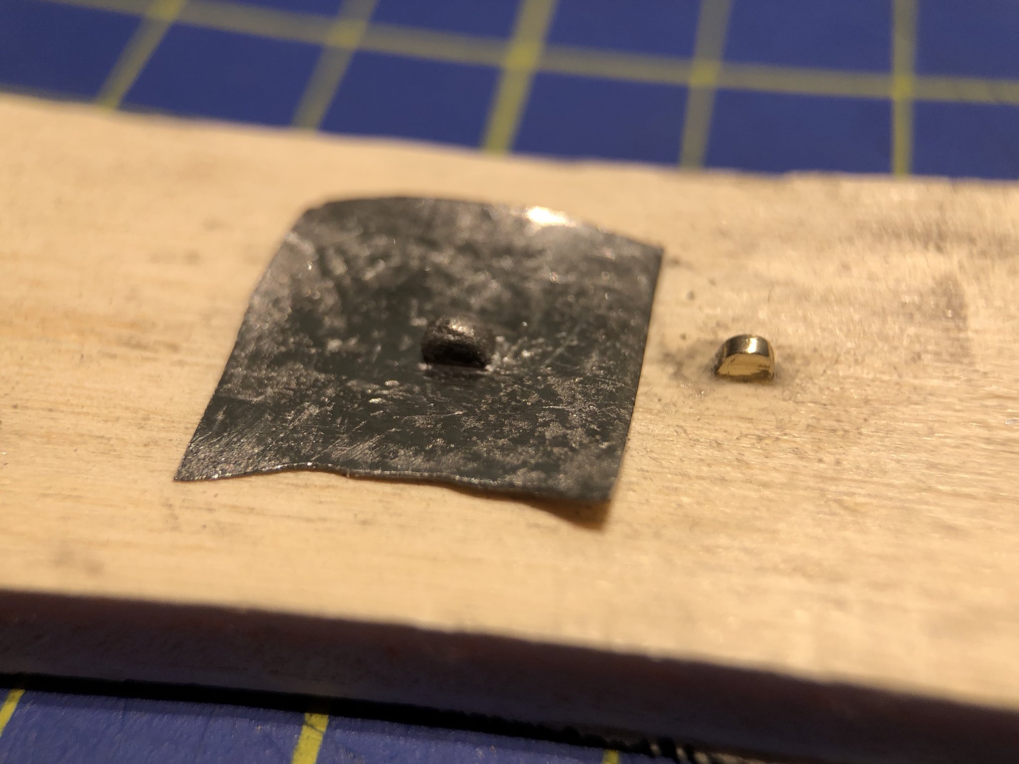
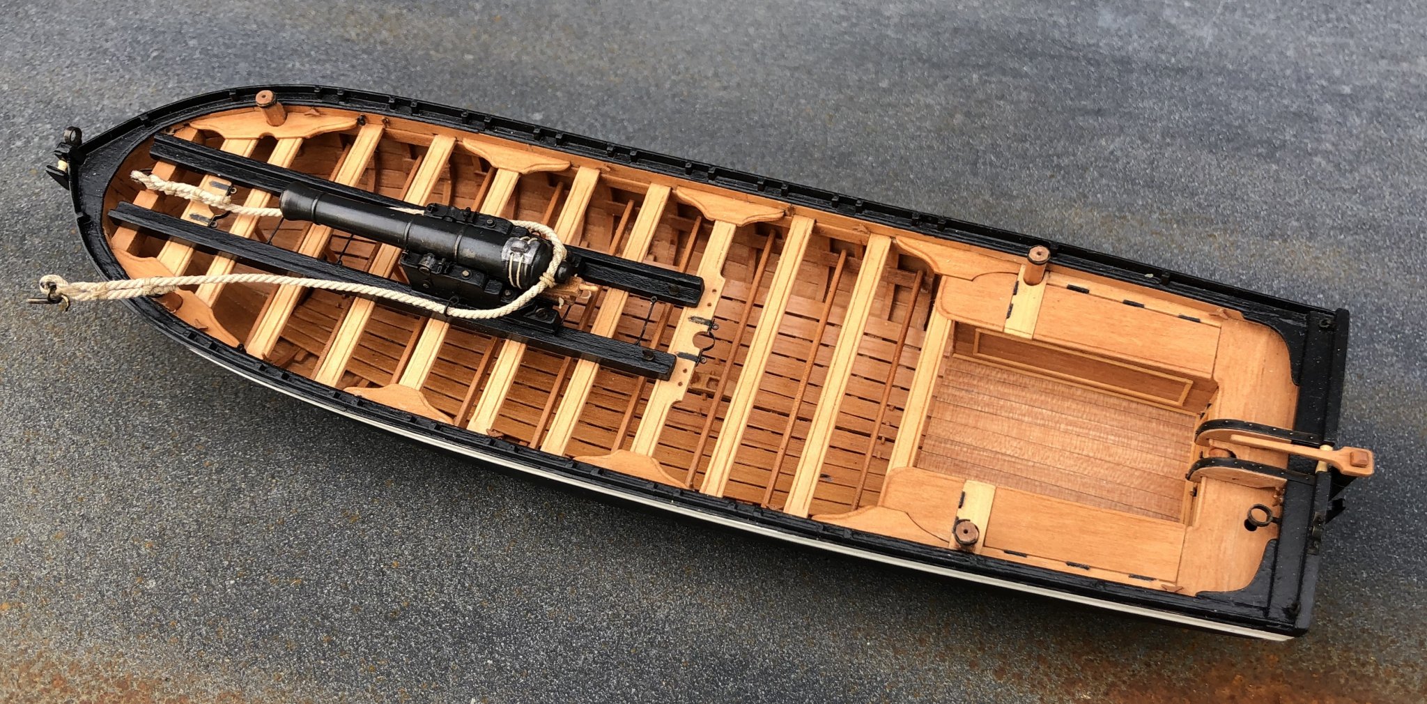
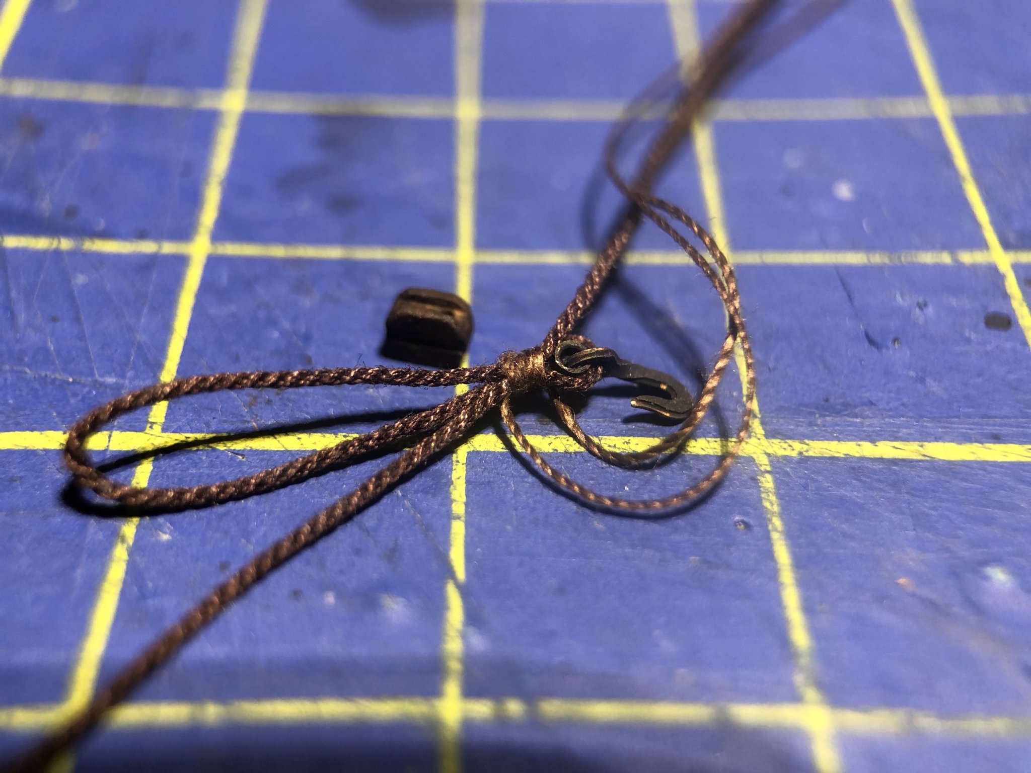
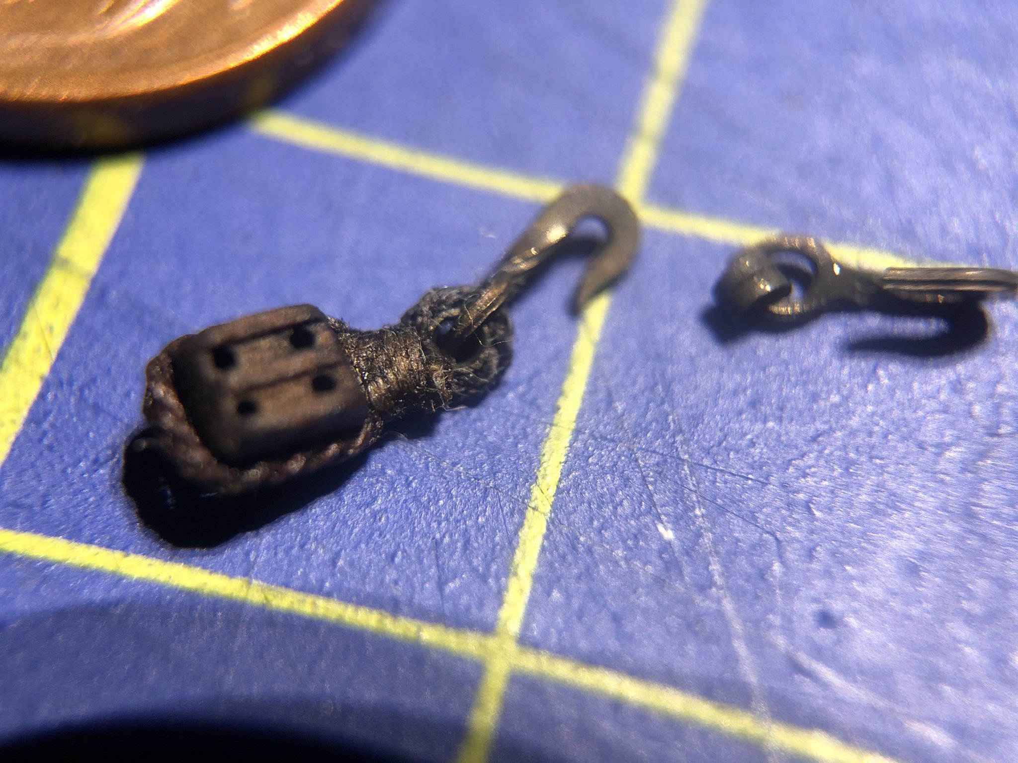
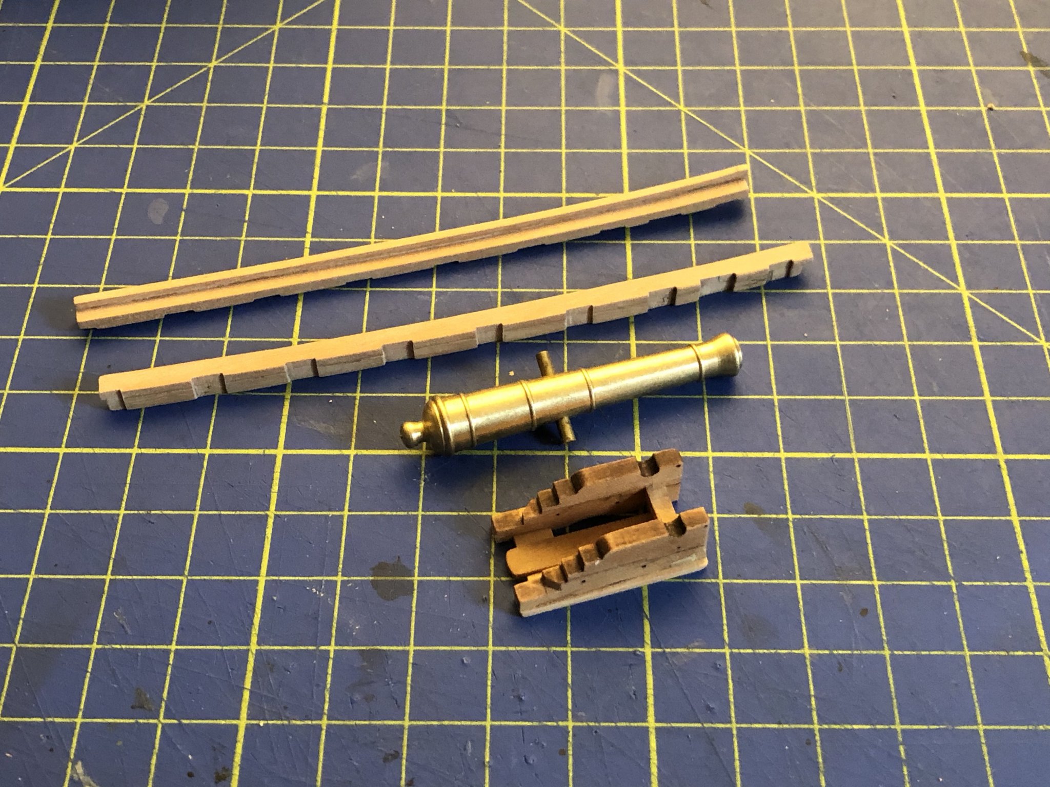
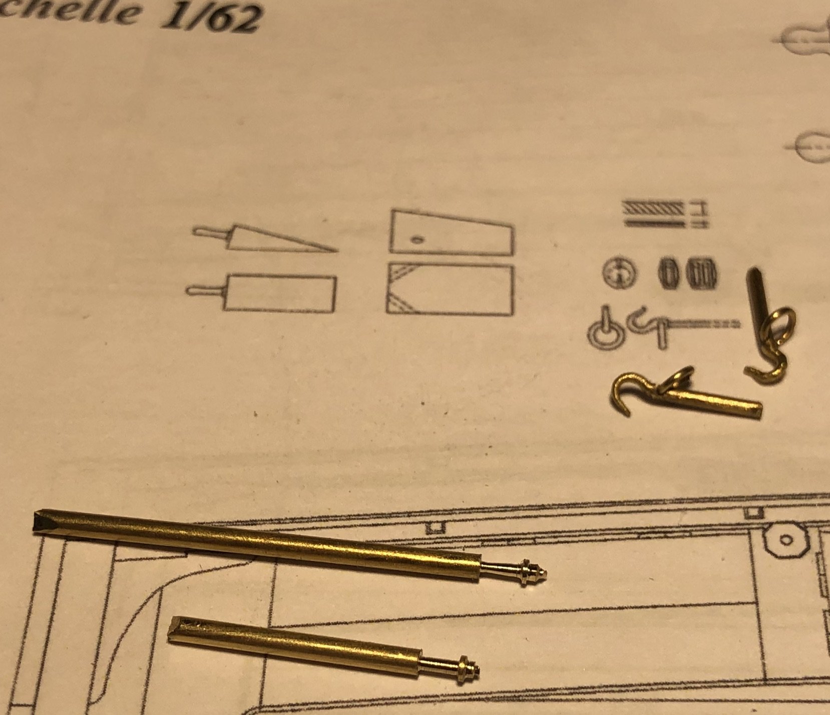
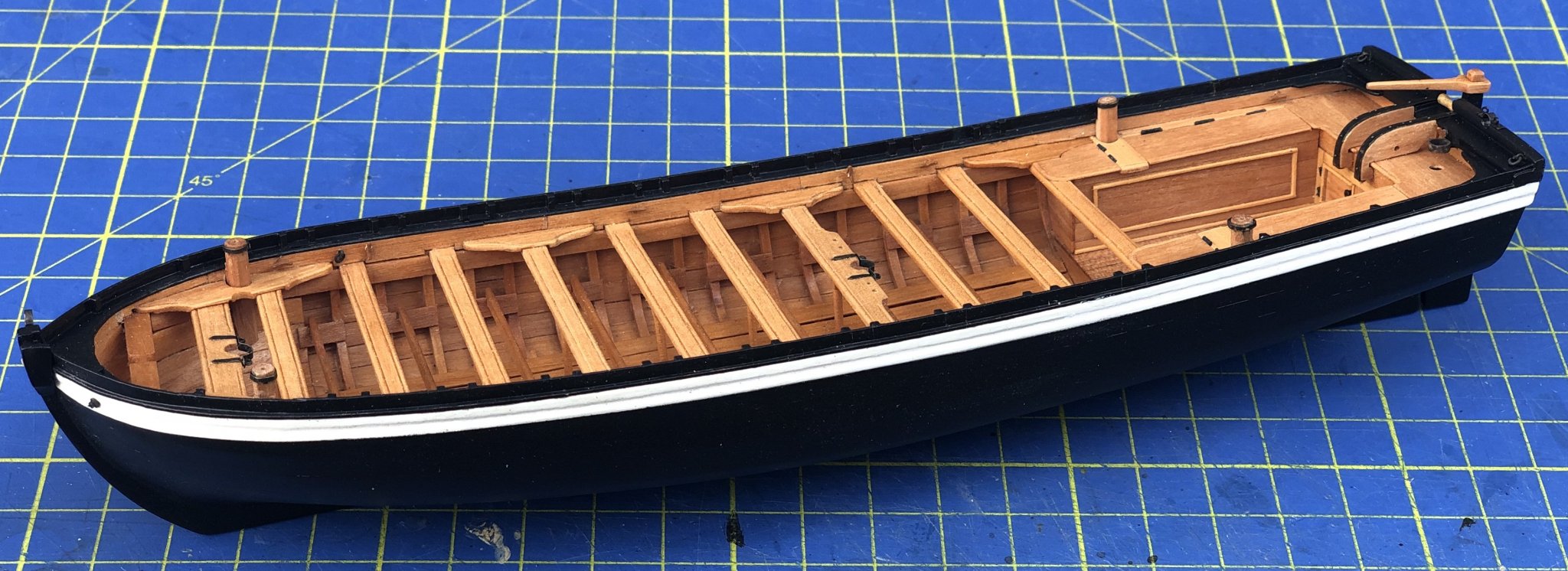
The gun barrel, the reason for the strange scale (1:62) is exactly 50 mm long (a little less than 2''). Its carriage fits into the slides. A (real) lead cover was hammered and formed over an (inexistent) flint lock for protection.; an idea I took from Johann's phantastic build of La créole ( For the side tackles I used Chucks 3 mm blocks. To be continued and finished soon...


-
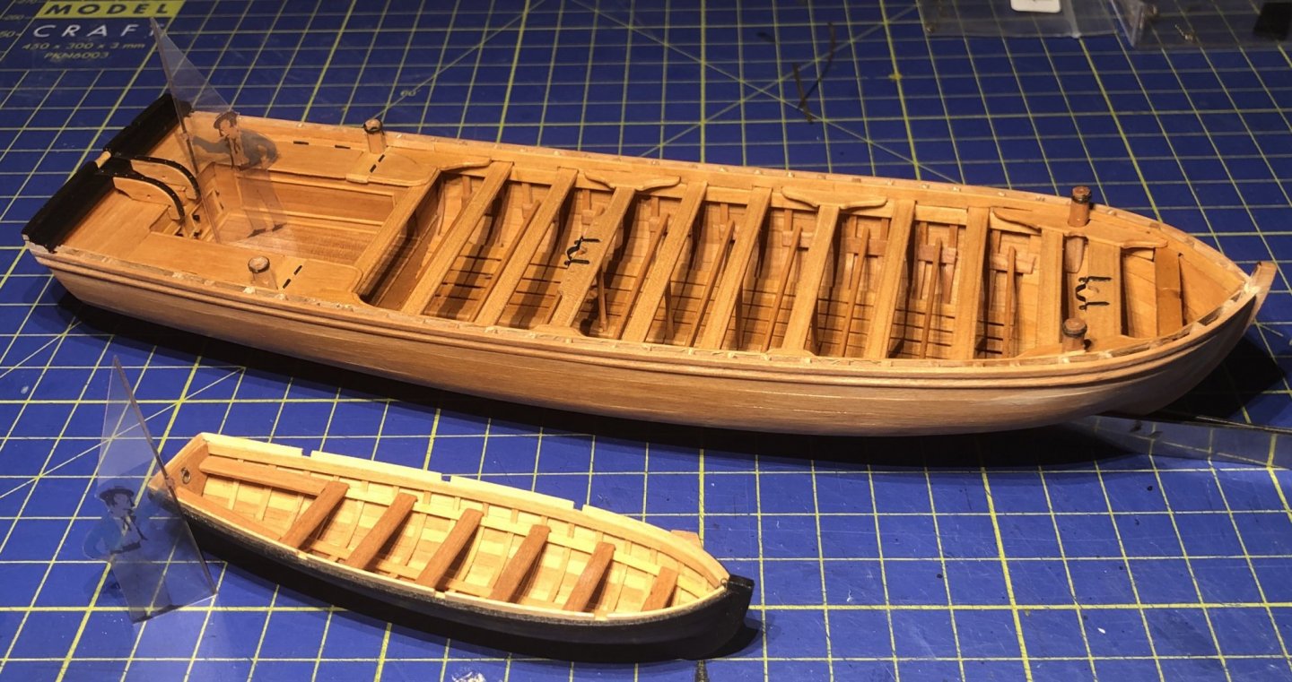
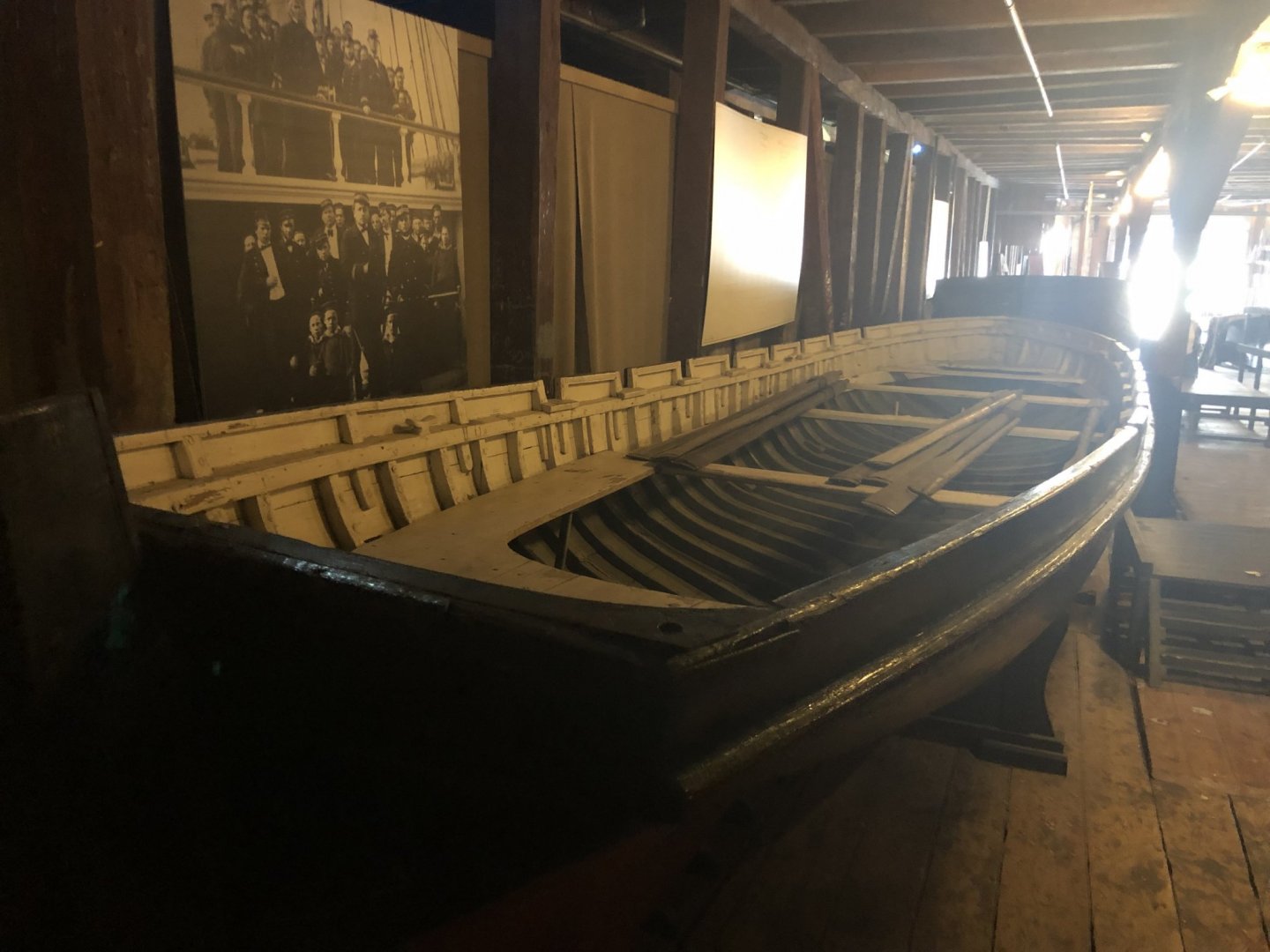
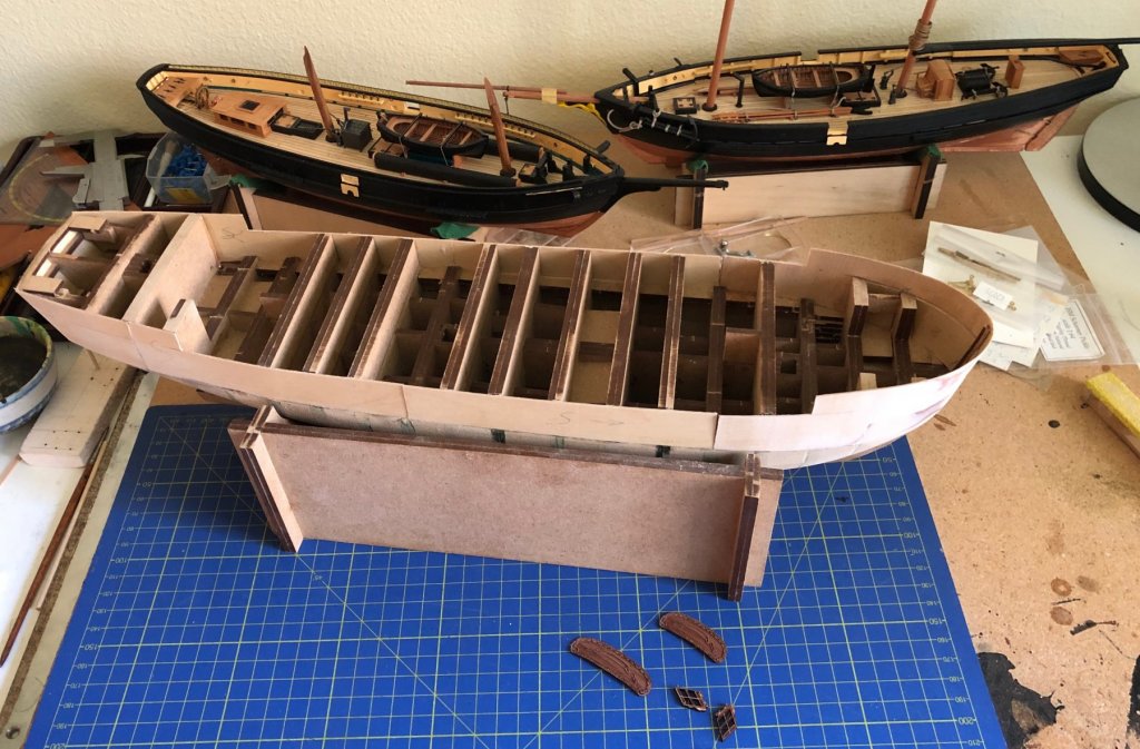
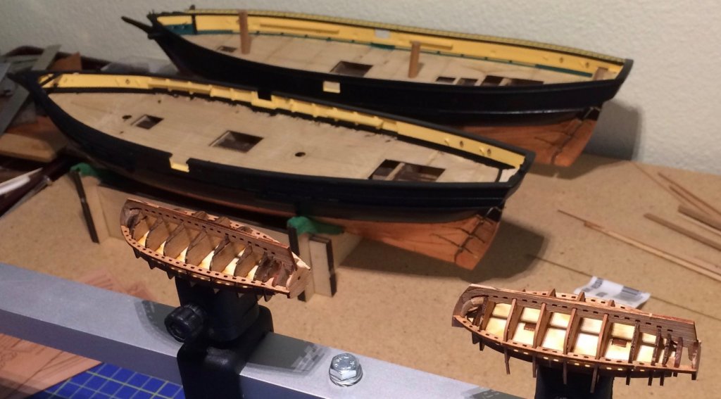
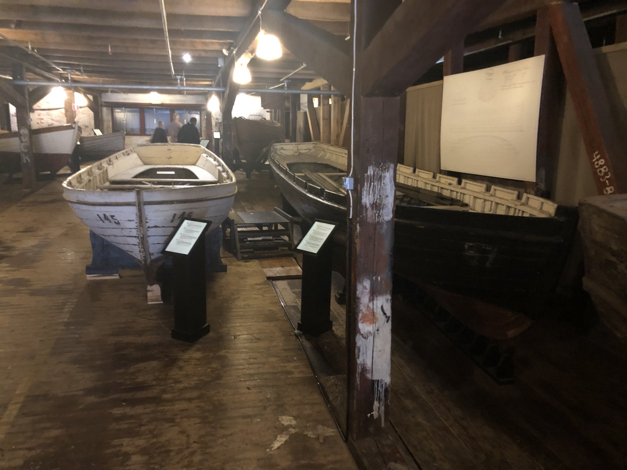
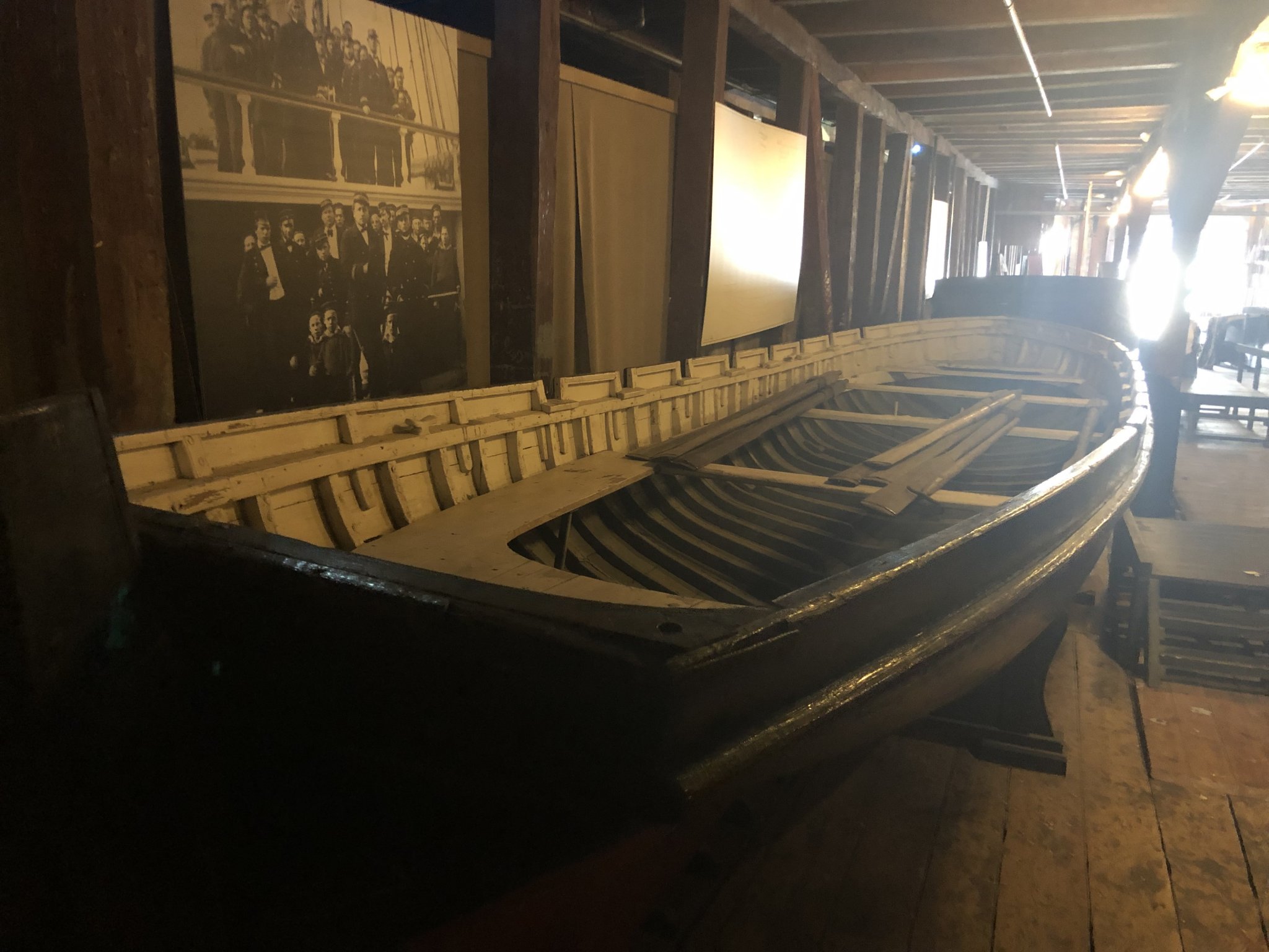
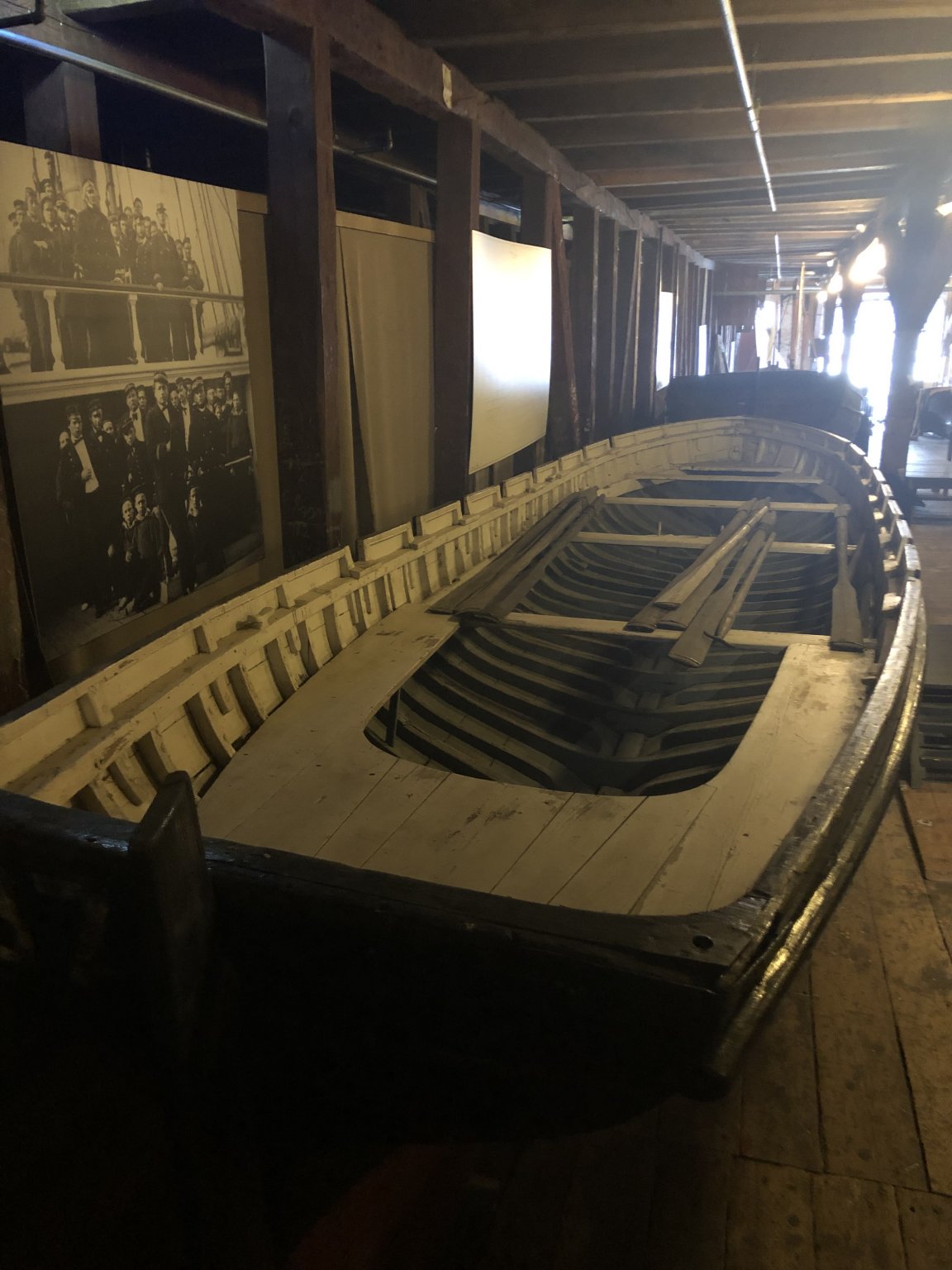
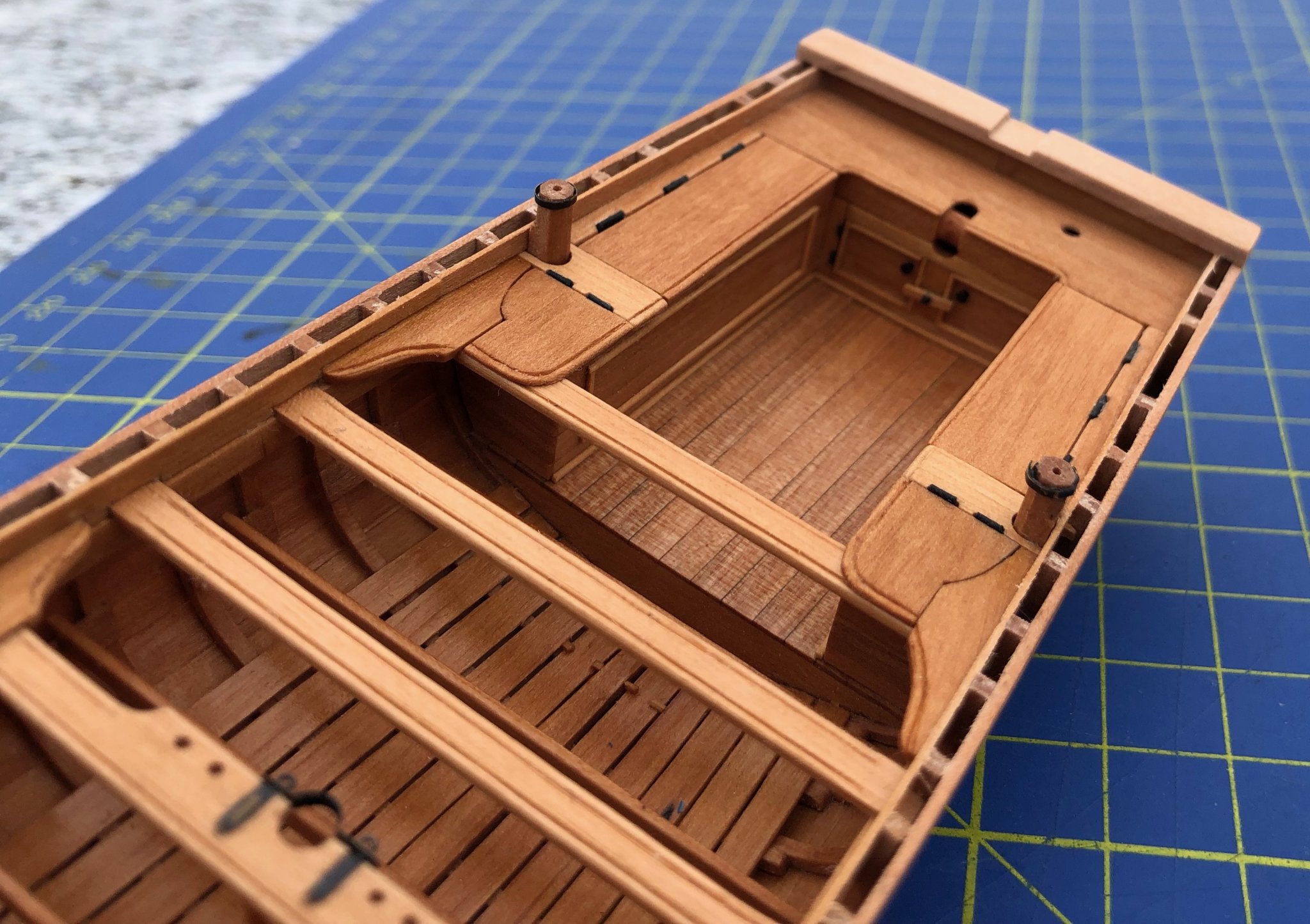
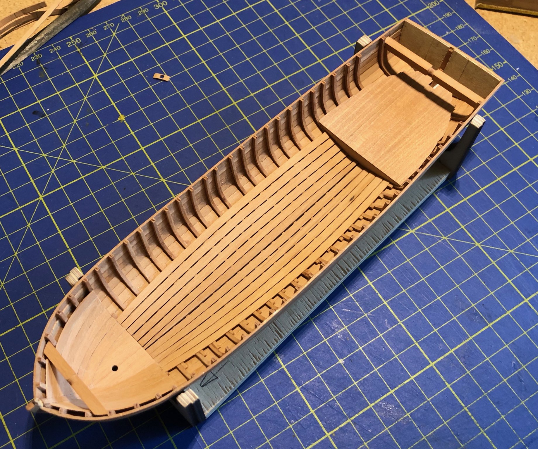
These gun boats were huge! They were 13 meters long (42 feet). A standard ship's cutter of 6 meters looks quite small in comparison. I was very lucky this summer, when I visited the city of Karlskrona, in Sweden. There is an excellent Museum, with a collection of small boats in a dedicated shed (difficult to take pictures inside...). There I found a sloop, built in 1833, of roughly the same size as my chaloupe! This was really impressive. To be continued soon...


- 15 replies
-
- 10
-
-
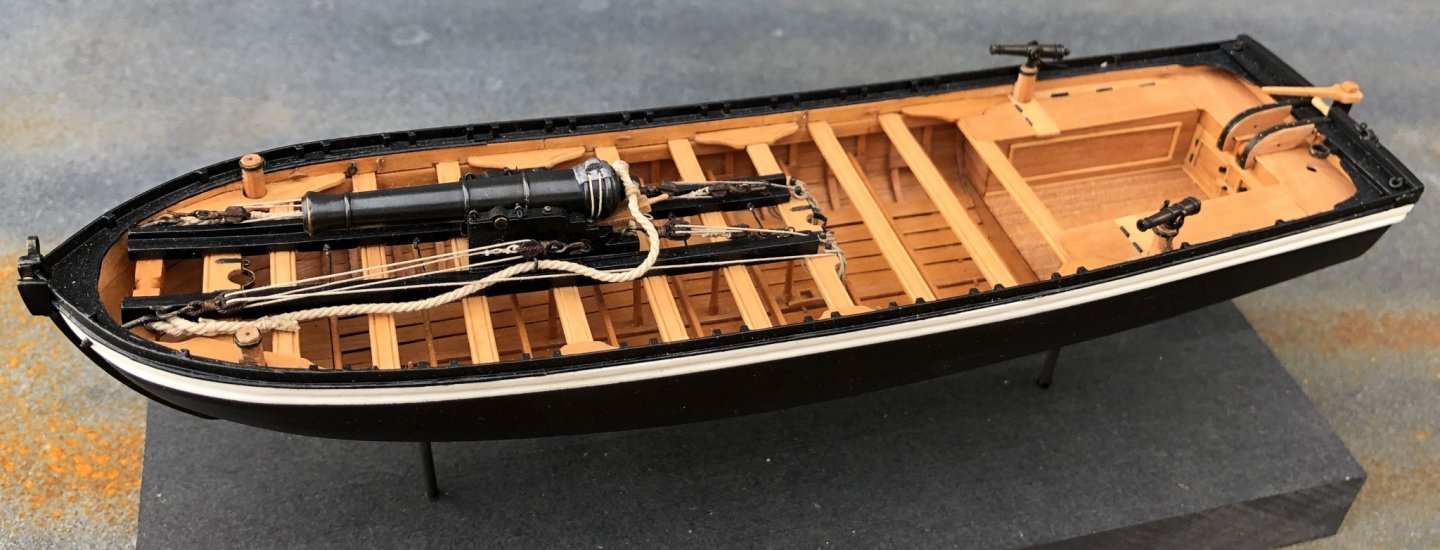
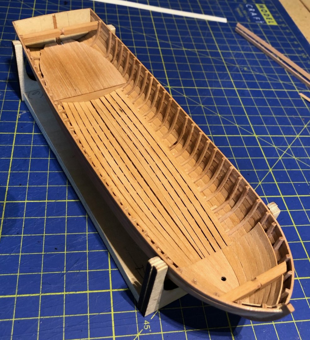
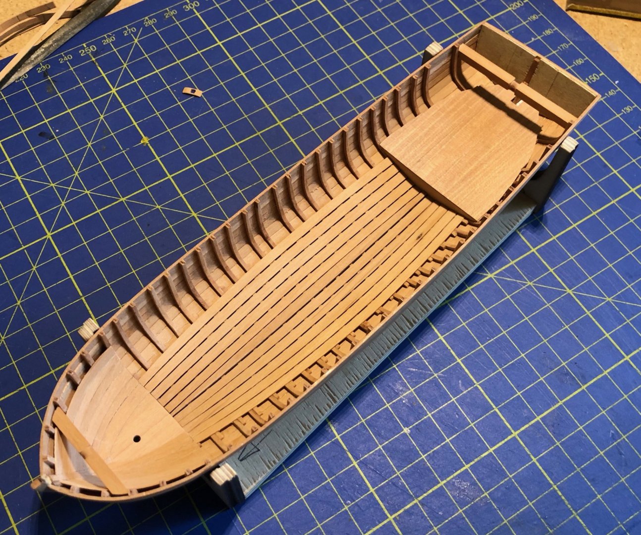
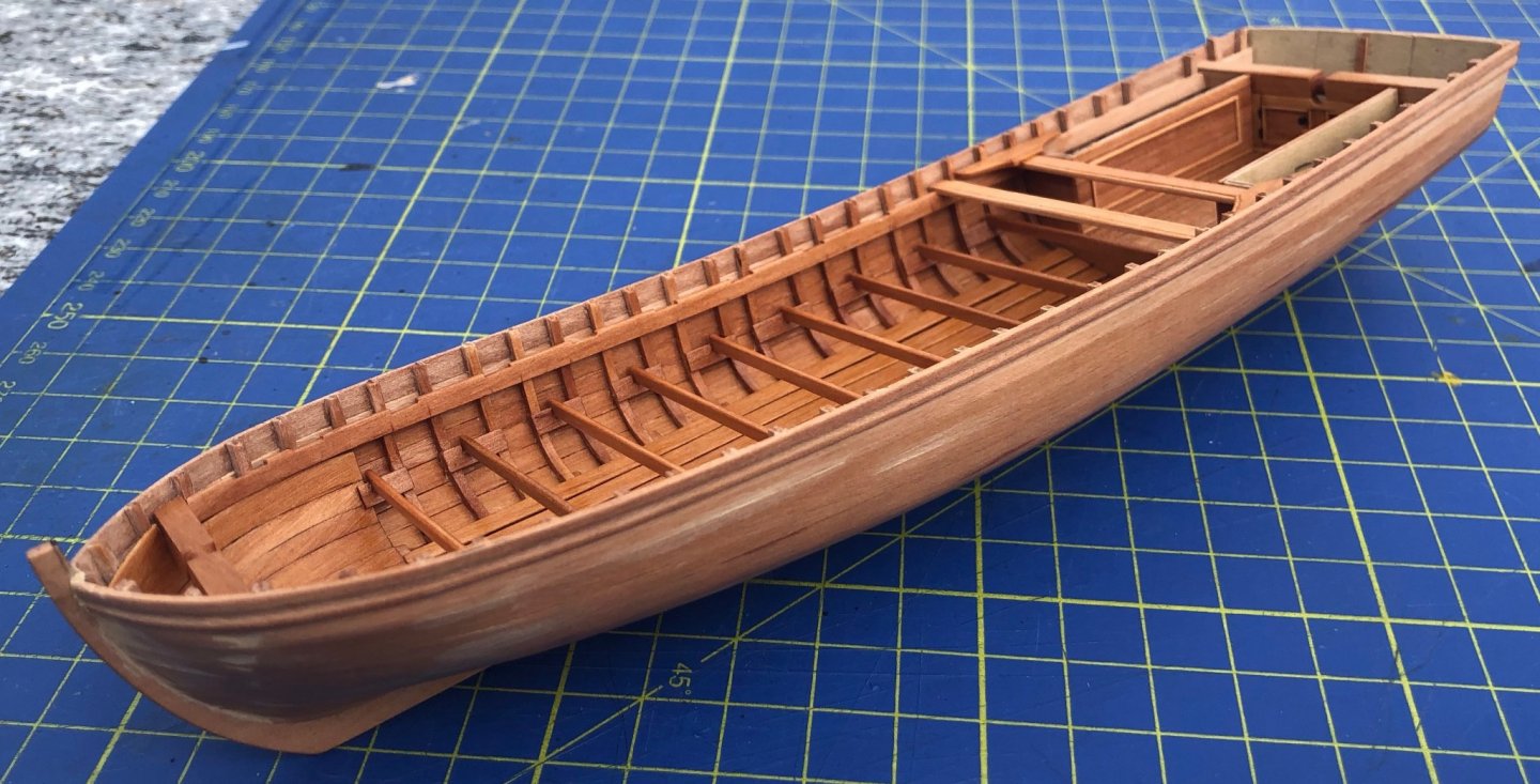
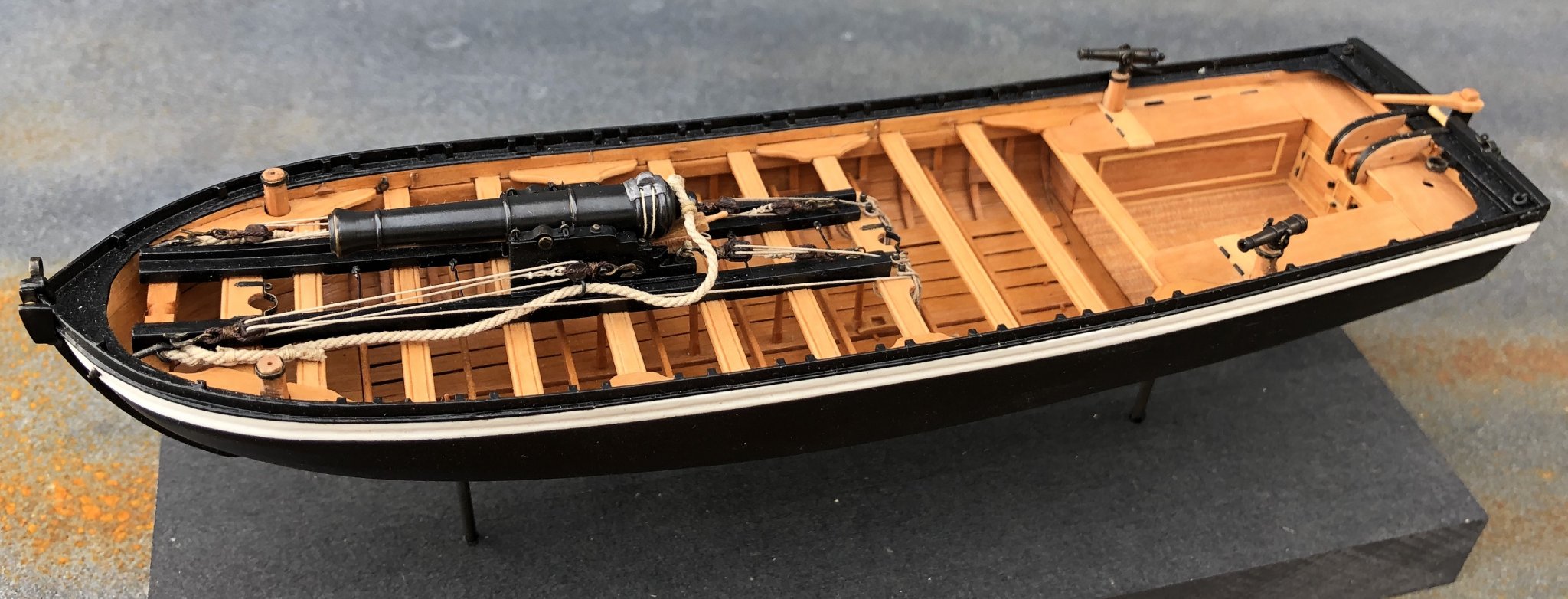
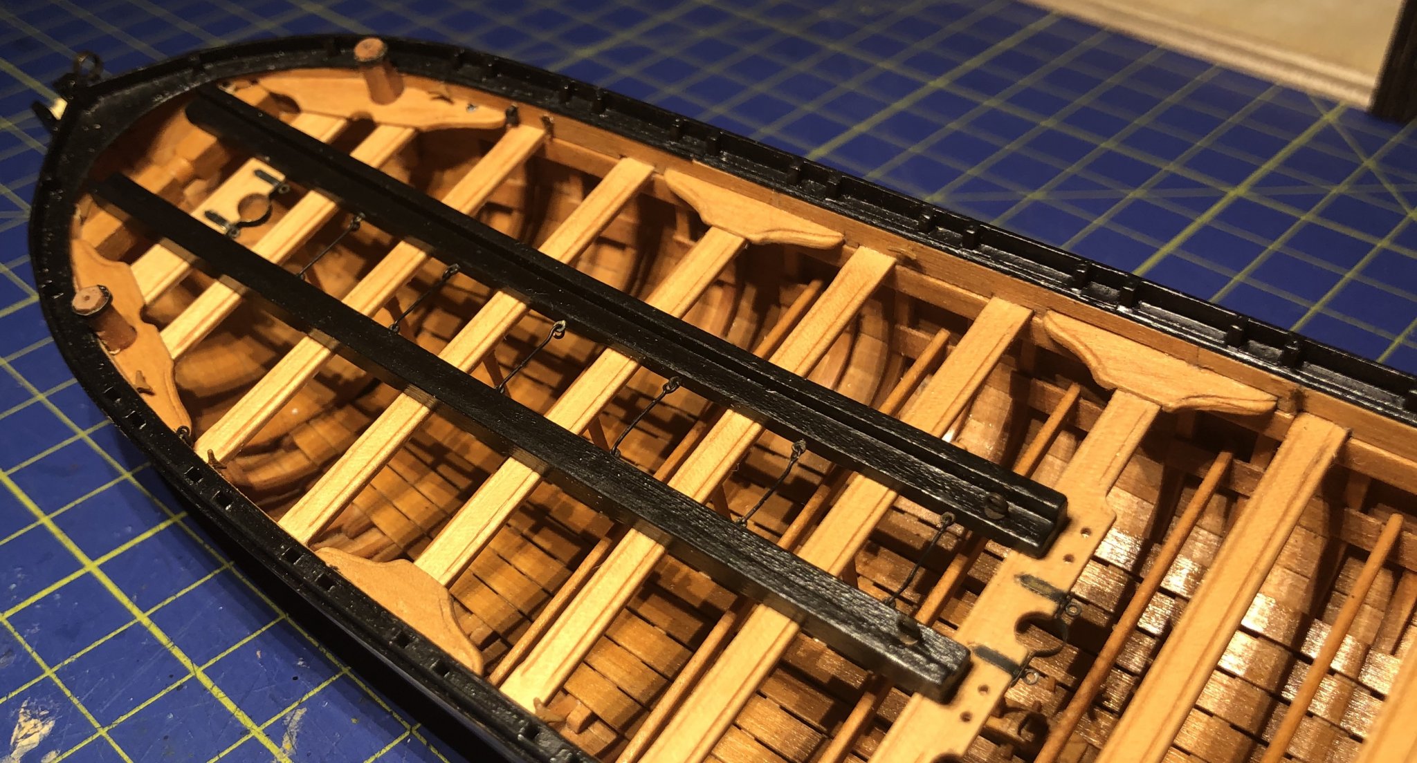
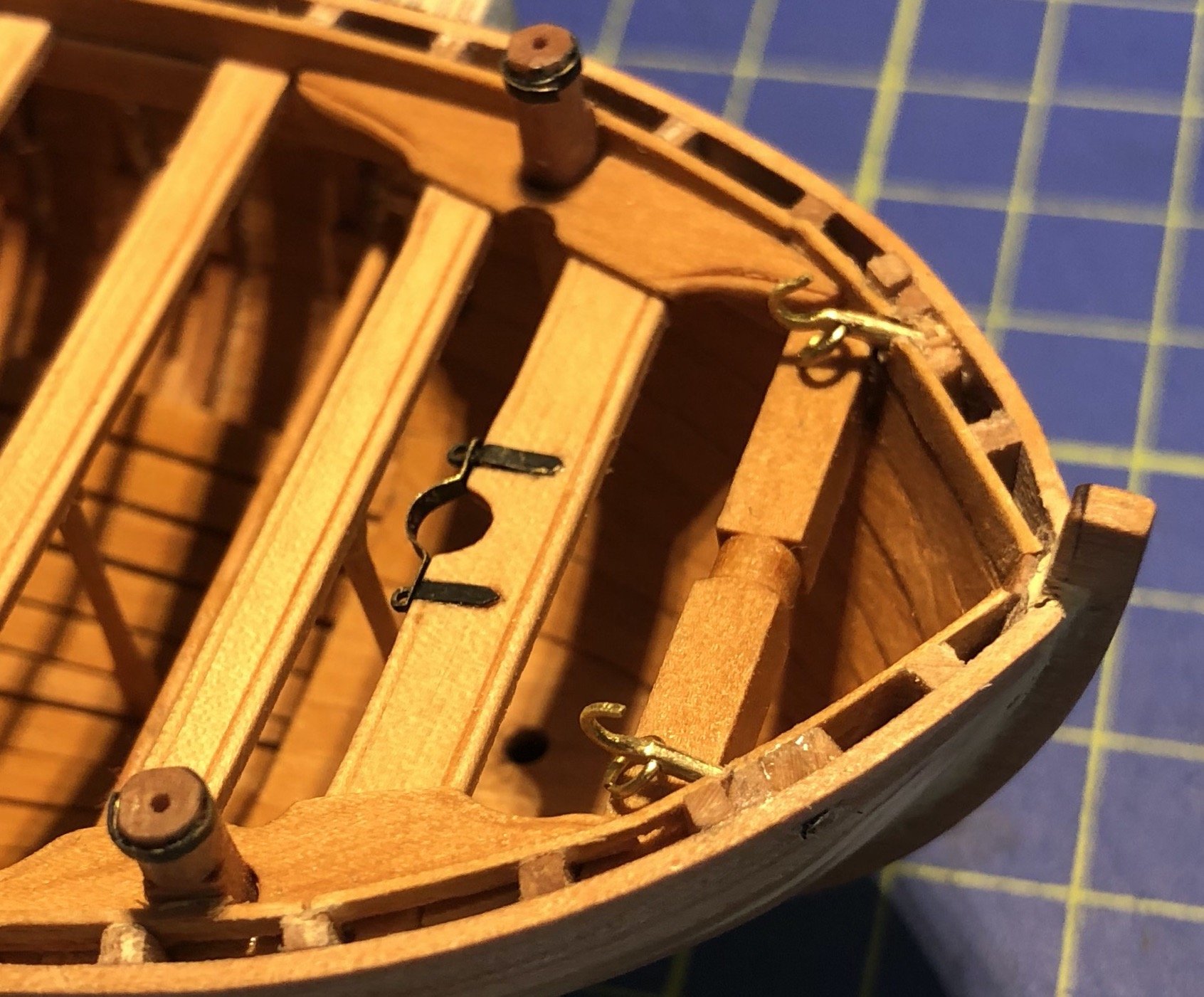
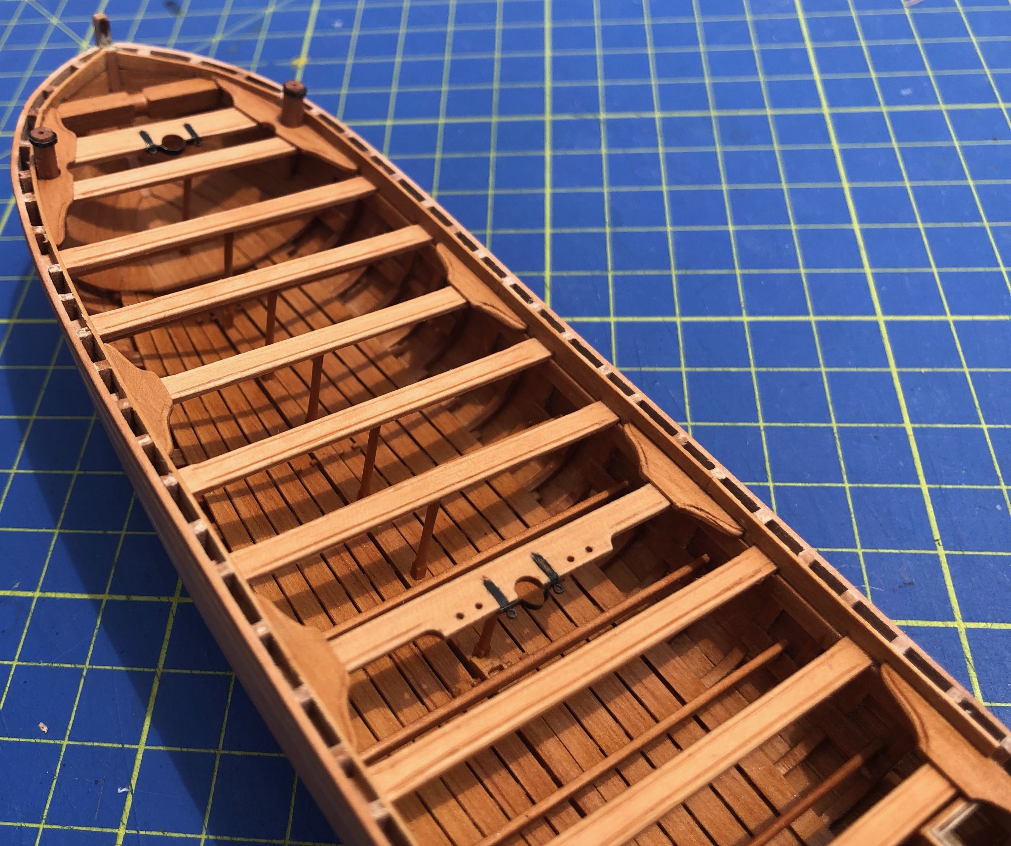
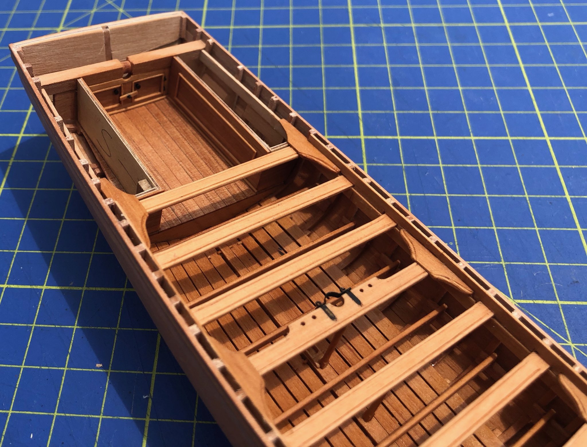
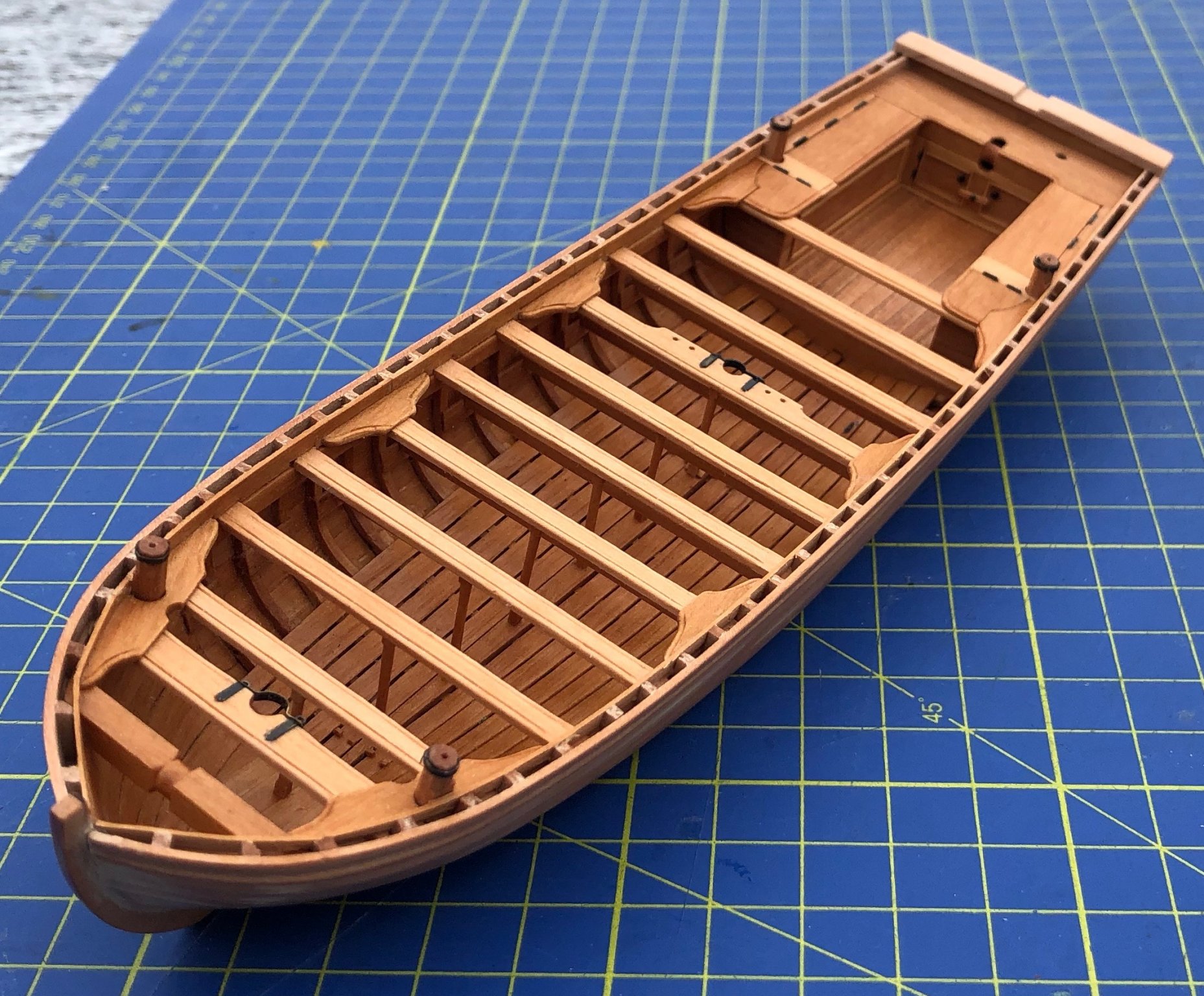
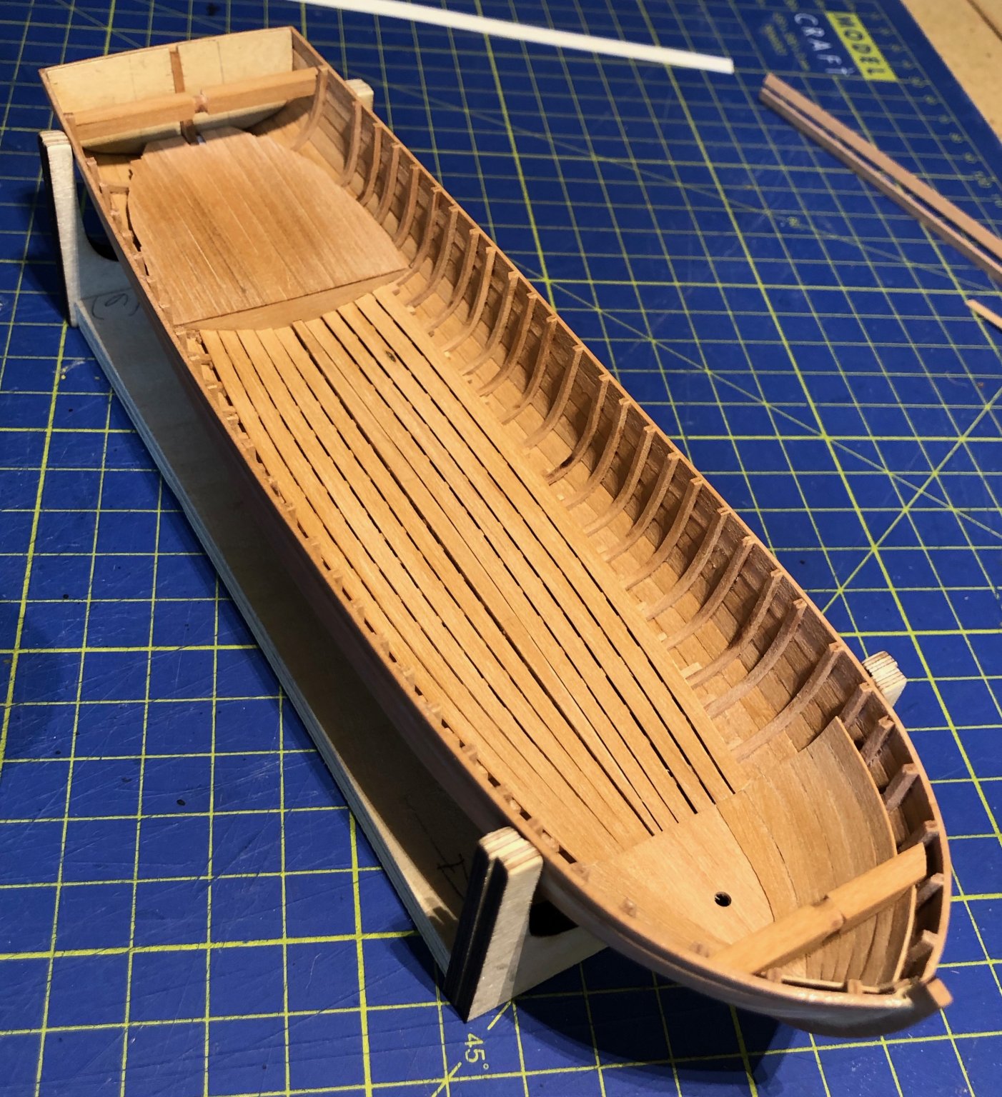
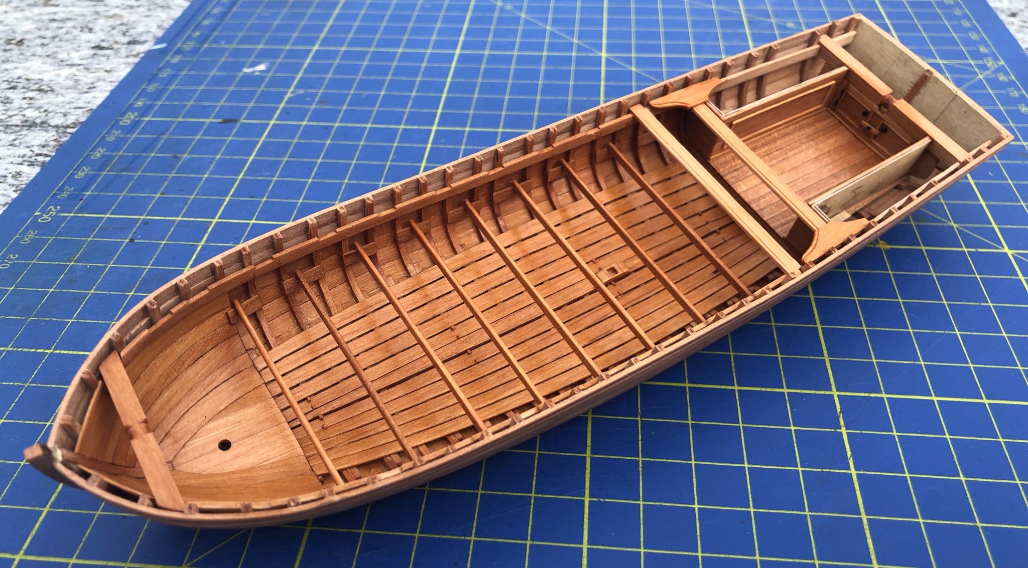
The interior: Floor boards were separated by paper strips while glue dries. The interior was then varnished with Danish oil. To be continued soon...


- 15 replies
-
- 13
-
-
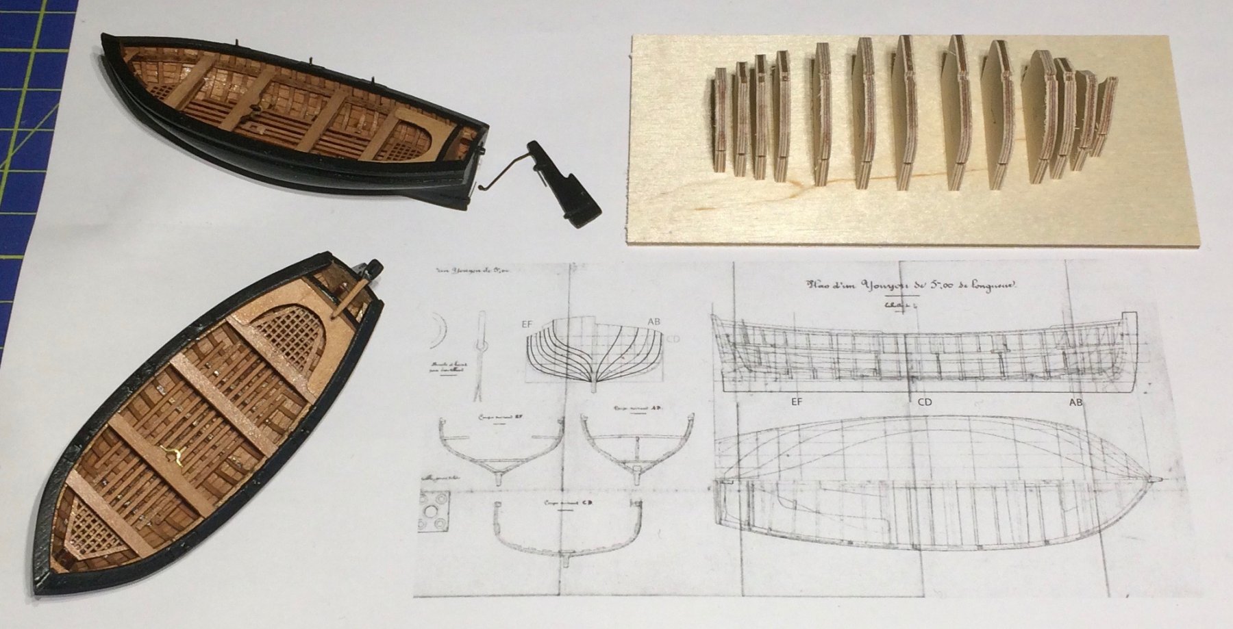
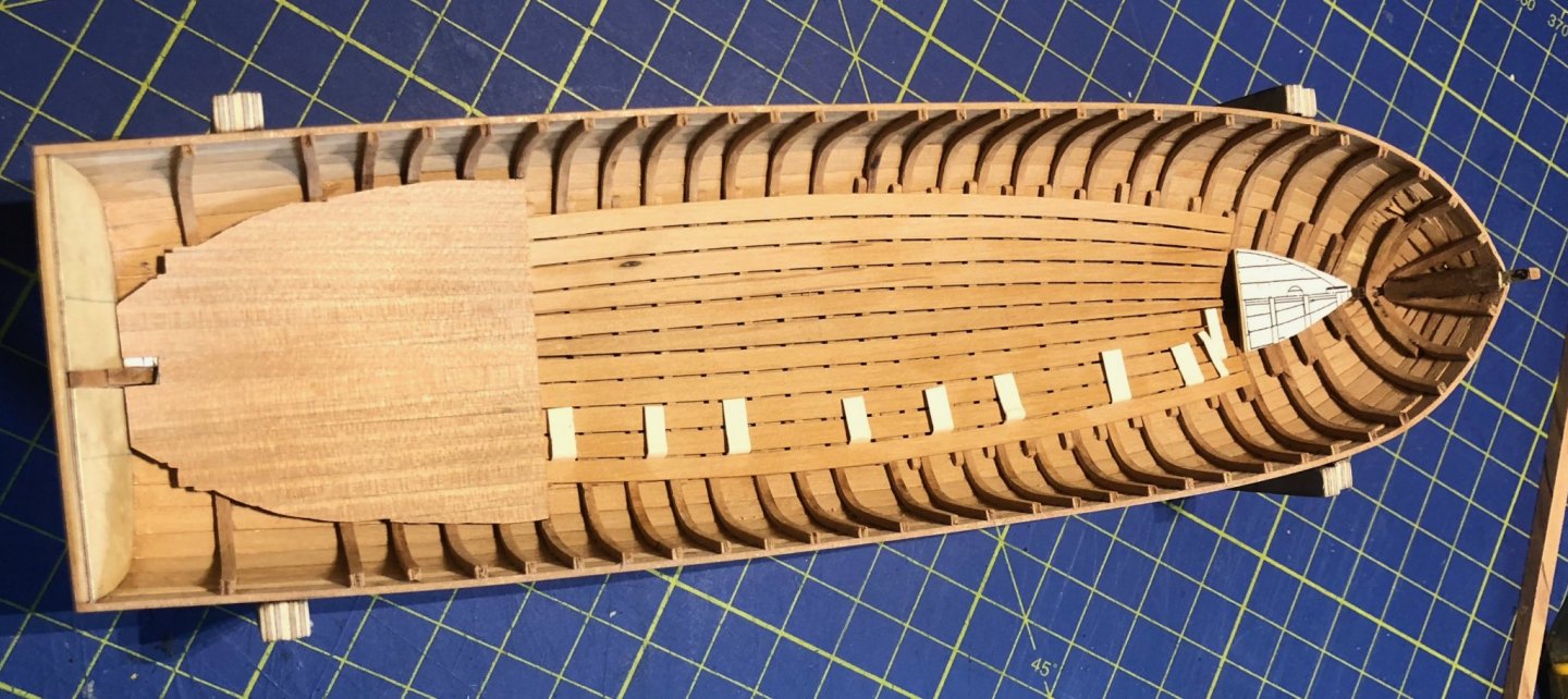
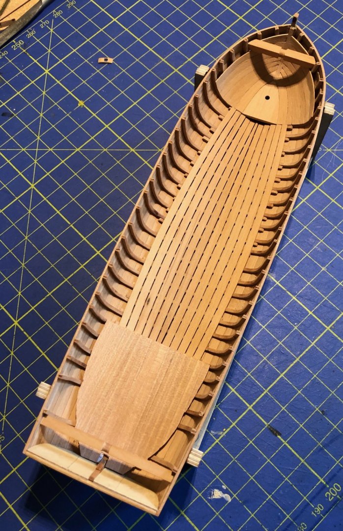
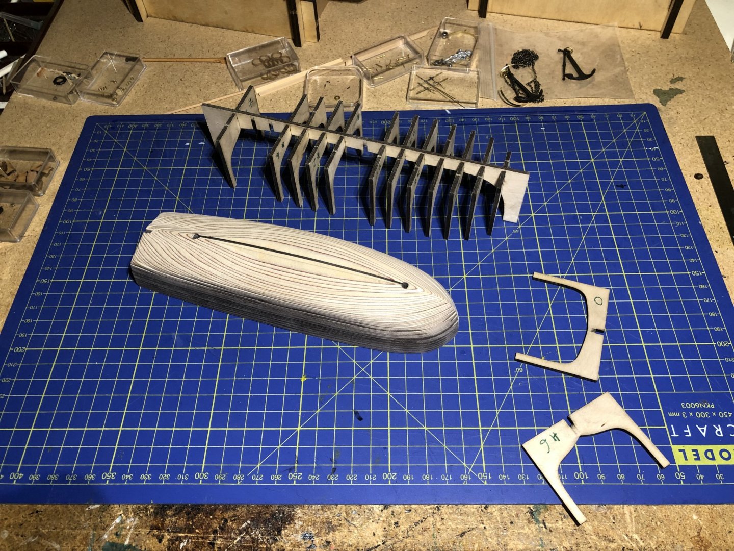
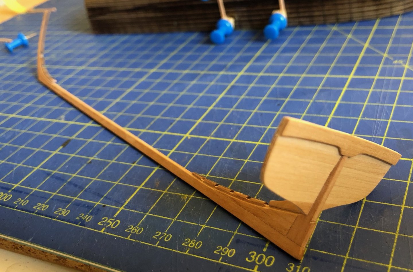
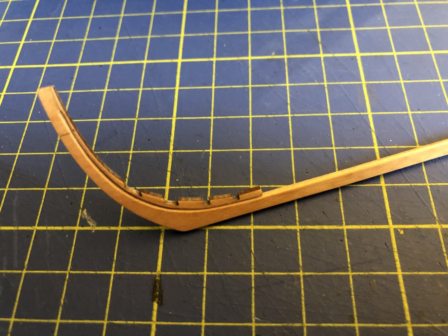
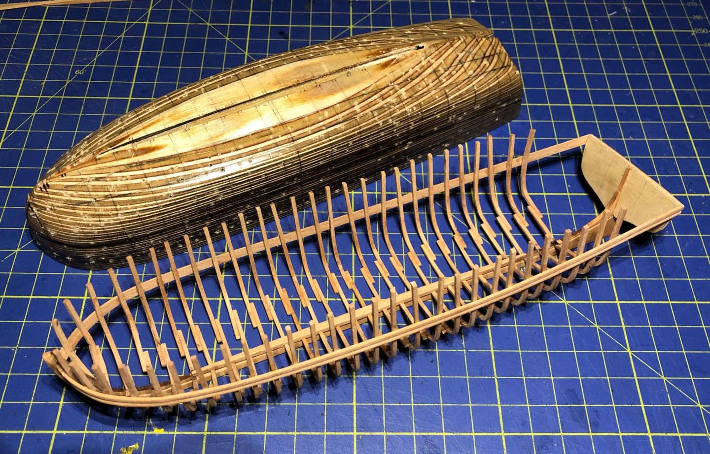
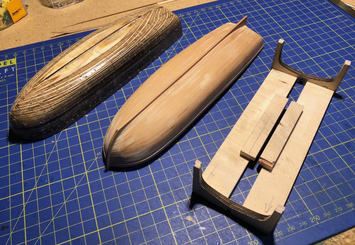
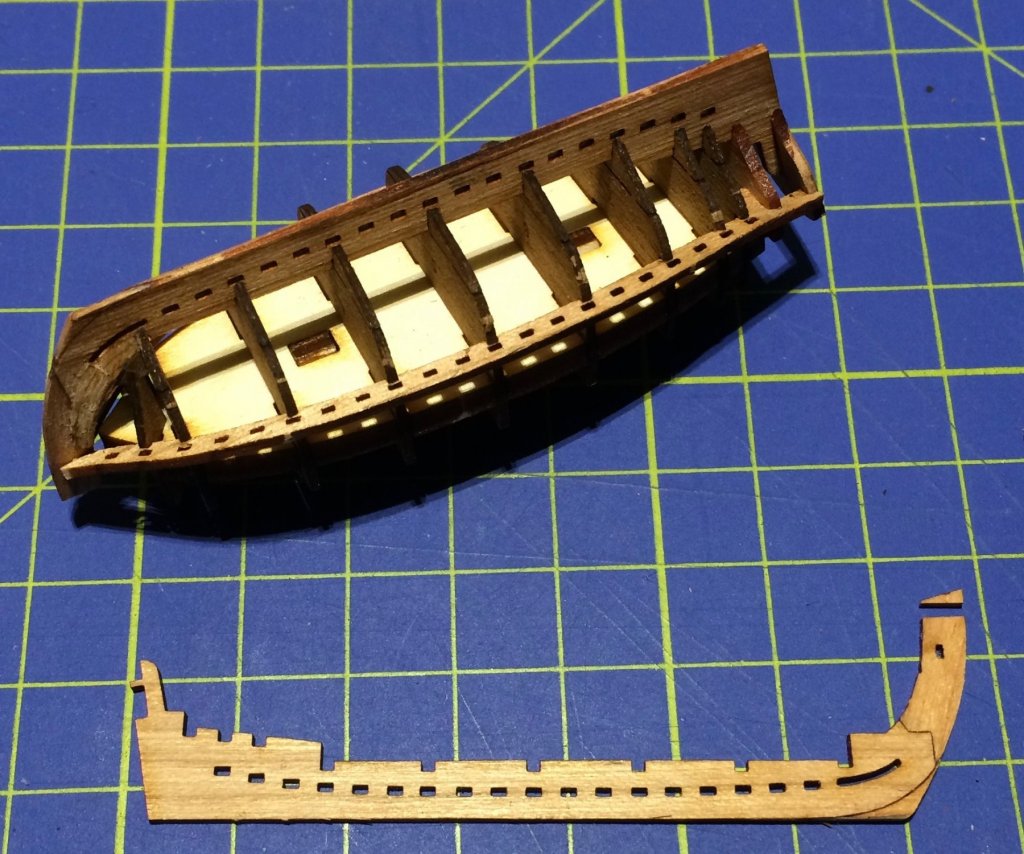
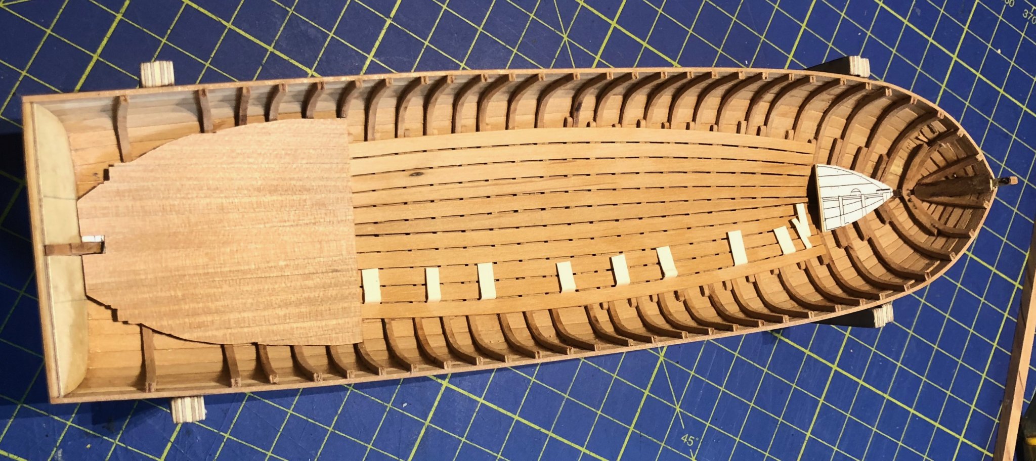
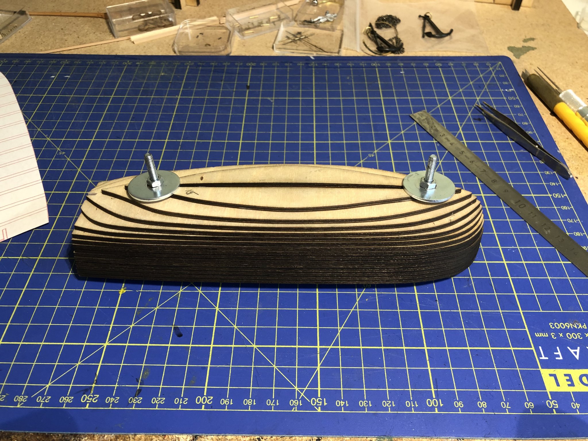
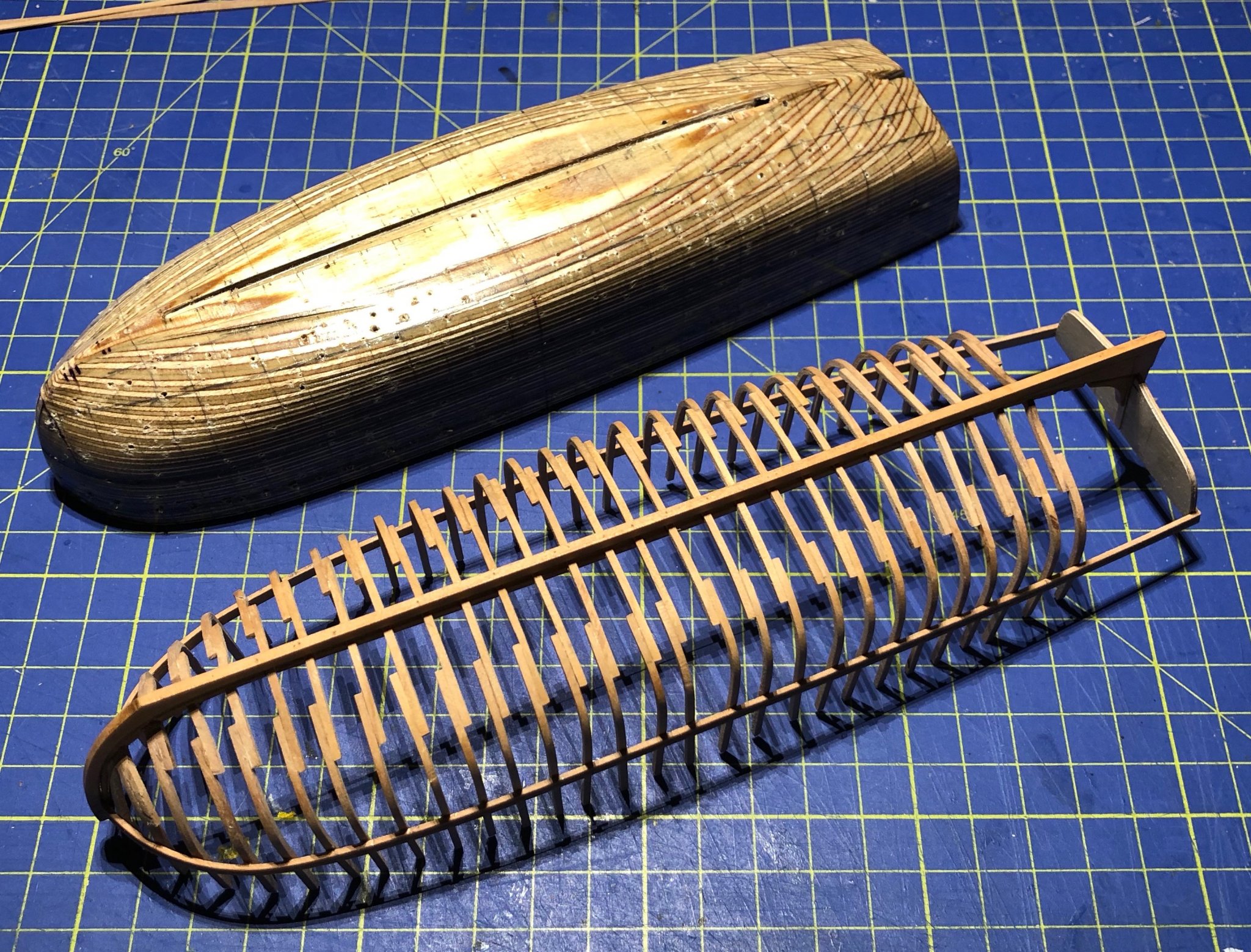
A litte more than a year ago I started a side-project. I bought the plans for this small boat on a whim, after visiting an excellent exhibition at Rochefort, France (thats where the famous frigate Hermione has its home port). The model is about 22 cm or 8.66142 inches long. Building this little gun-boat gave me great pleasure and quite a few headaches, mostly due to my choice of a small scale of 1:62 (I scaled the plans down to fit the gun barrel from rb-models in Poland). The plans and explanations (ancre.fr) are excellent, available in several languages - even in my native German. Here I will keep my explanations short. I recommend the - as always - very instructive log by Tony with further references. My chaloupe is made from pear, painted in French style of the time (with the exception of the imperial green on the inside, which would made it more historically accurate). So here are the first steps: Keel parts assembled (2 mm pear) The frames (1.2 mm pear) were watered, bent over a soldering iron and pinned on the form (with a shortcut at the stern, where no frames were needed for this model), covered with glossy synthetic-resin varnish. Planking was done with 0.5 mm pear planks To be continued soon...


- 15 replies
-
- 10
-
-
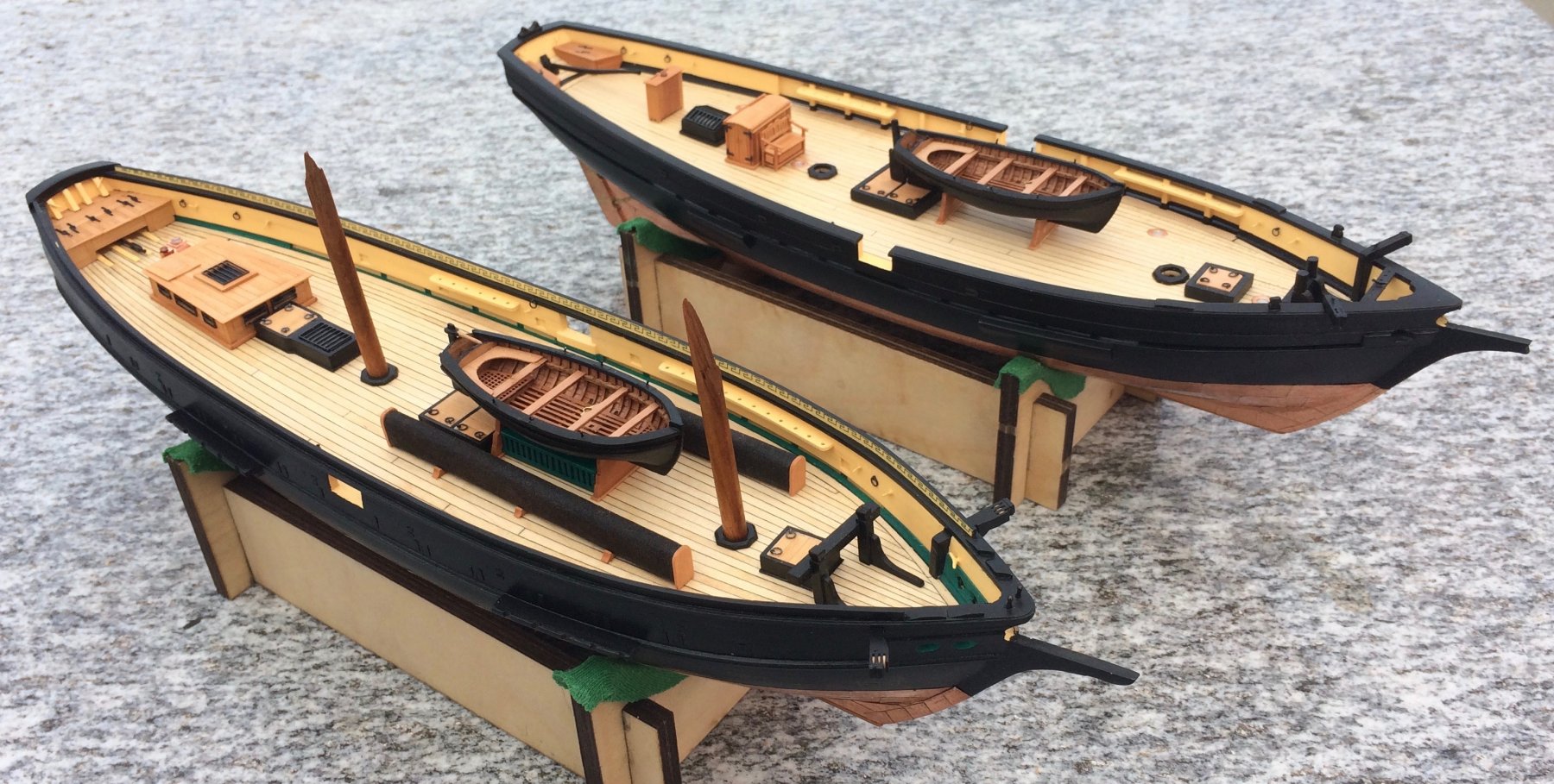
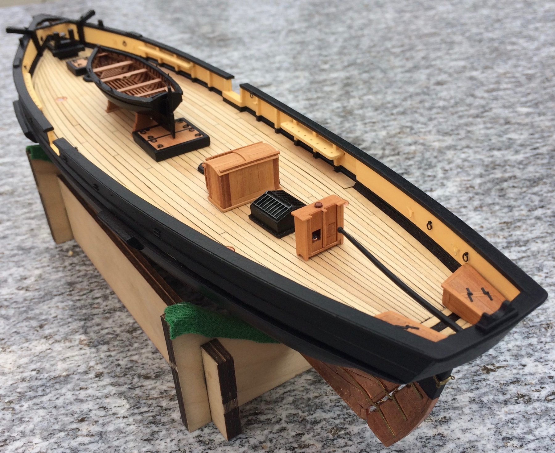
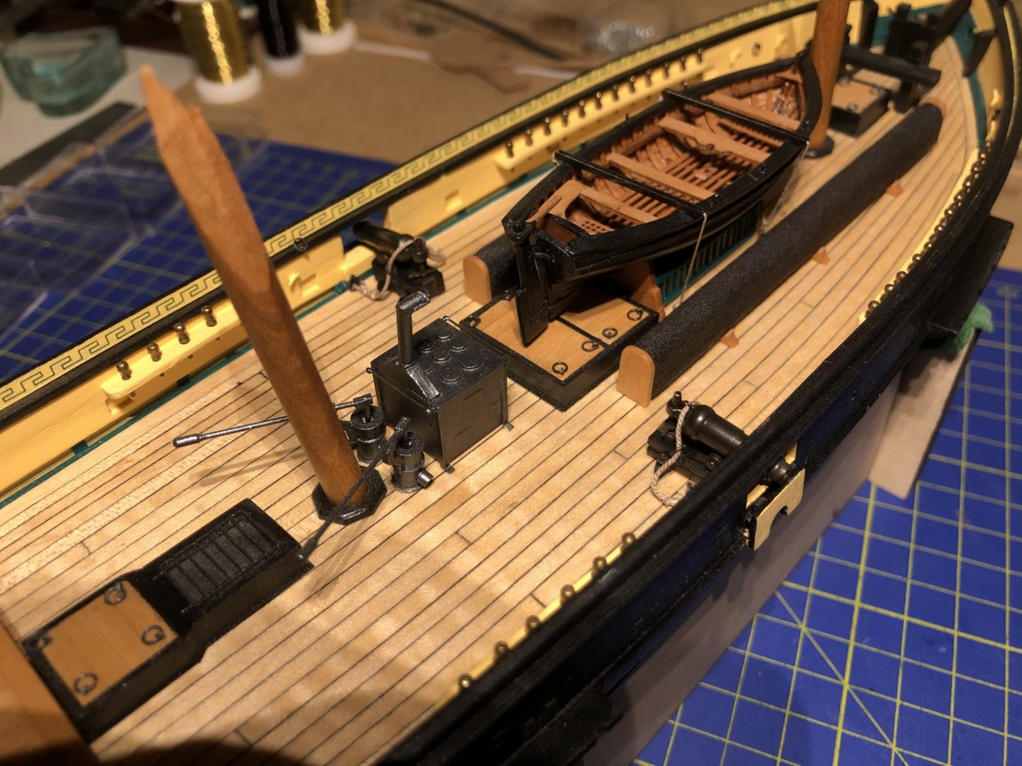
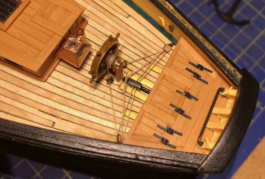
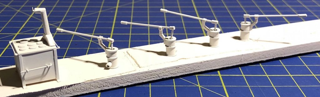
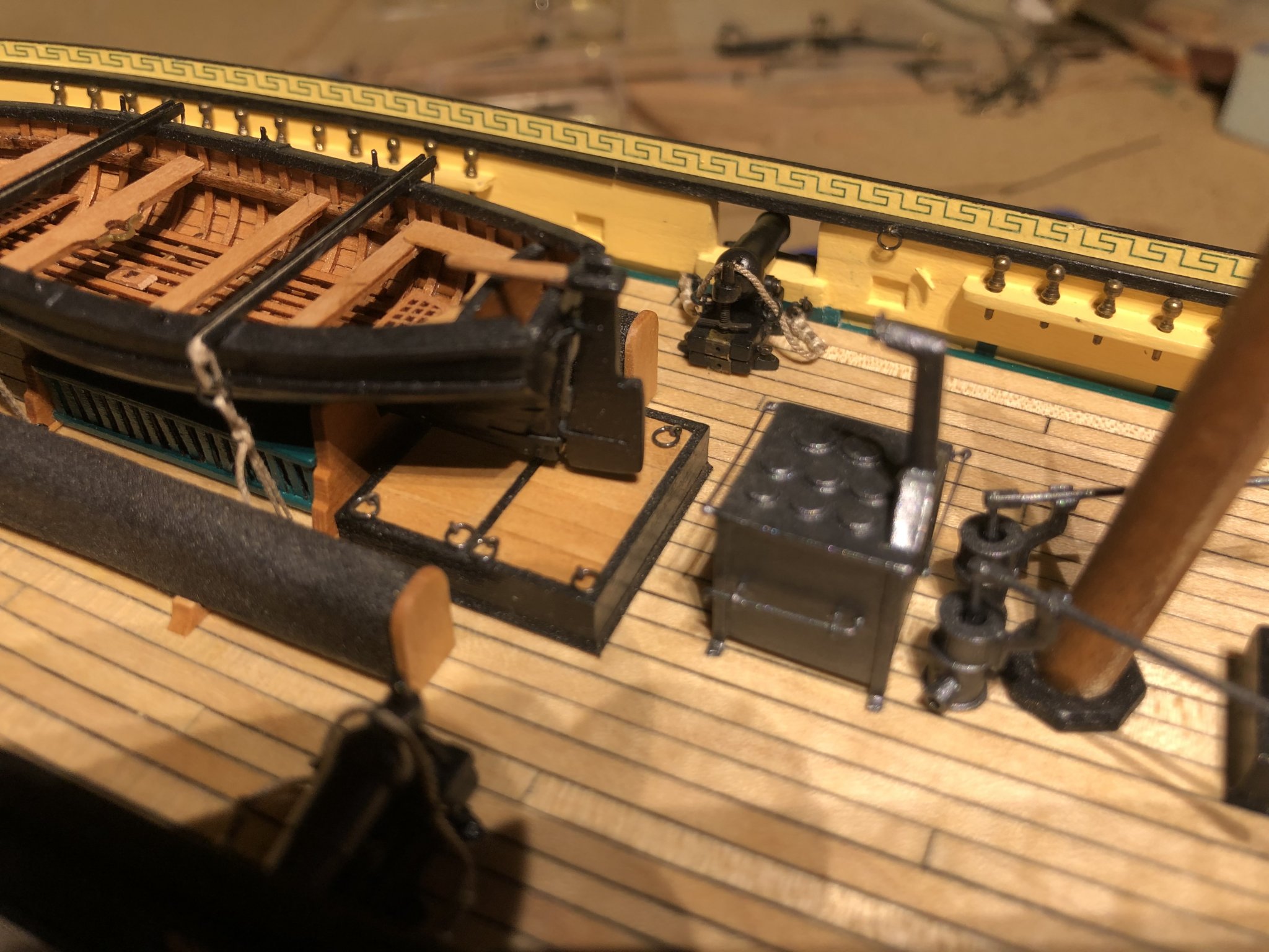
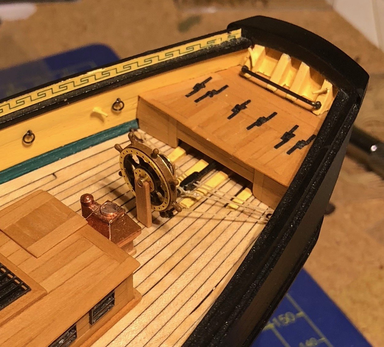
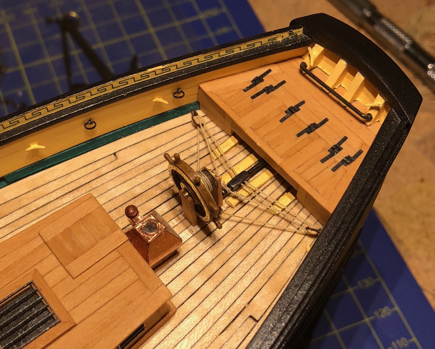
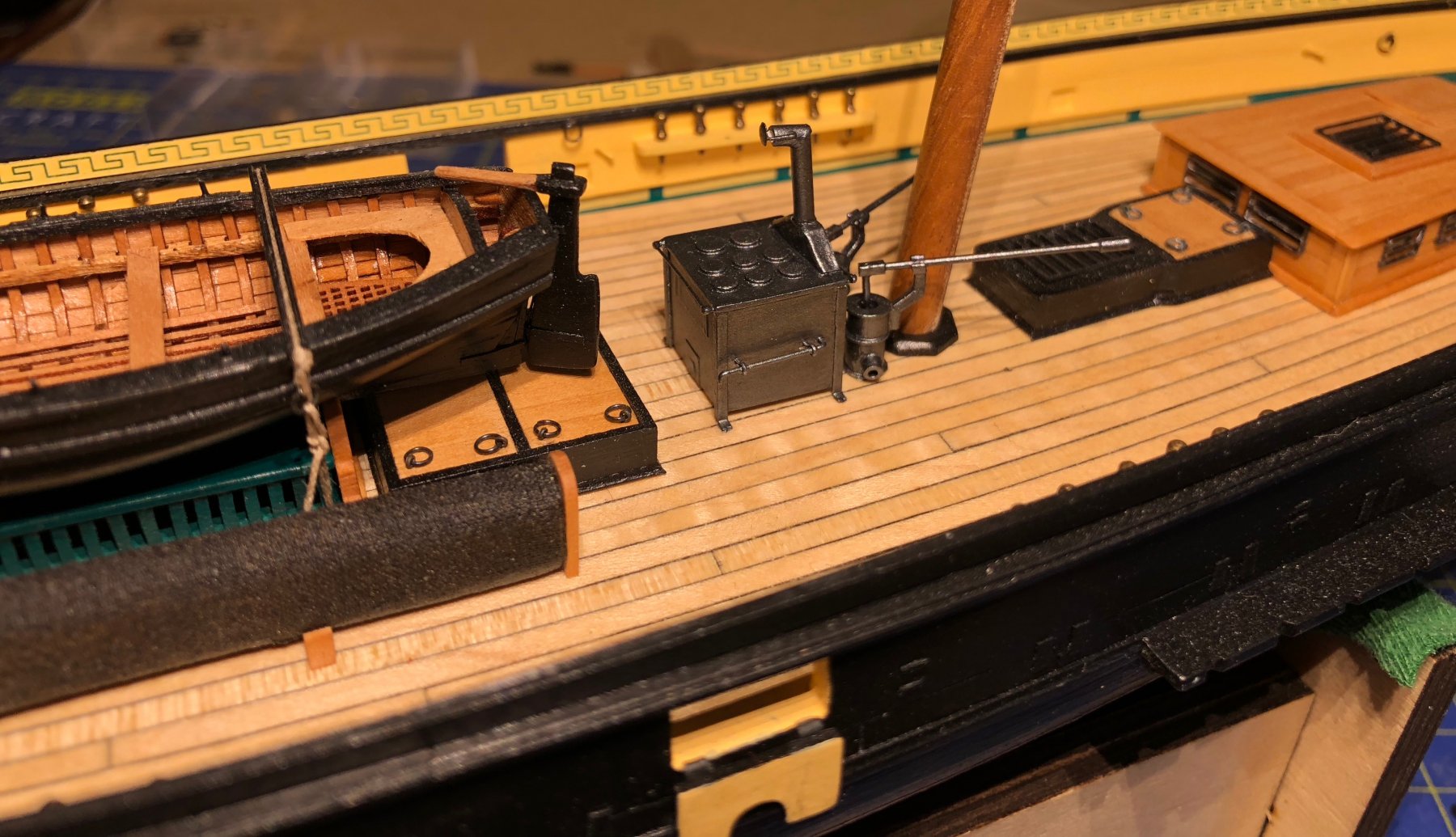
It's nice to be back, Tony (and discovering your Chaloupe, too). I bought the wheel, 17 mm in diameter, from Caldercraft. It was a perfect fit for La Mutine. Stove ans pumps were made from a wild mixture of materials: A wooden dowel, washers and polystyrene profiles for the pumps, with a brass rod and tube for their handle. A wooden cube, a thin polystyrene sheet and paper, brass rod, polystyrene profiles and lots of glue. Then paint, to cover it all. I hat great fun making them. Gregor
- 121 replies
-
- 4
-
-
- la jacinthe
- schooner
- (and 2 more)
-
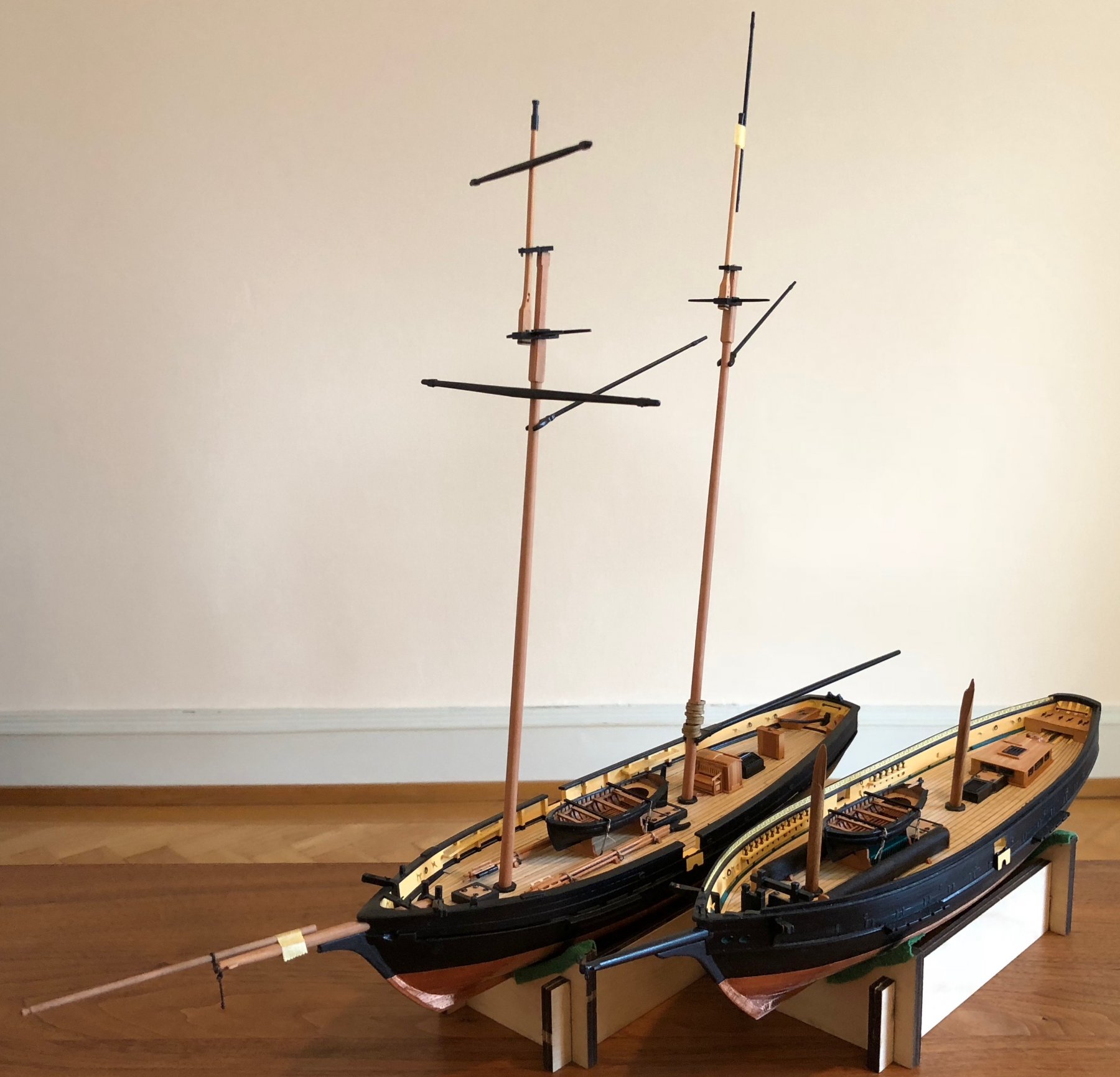
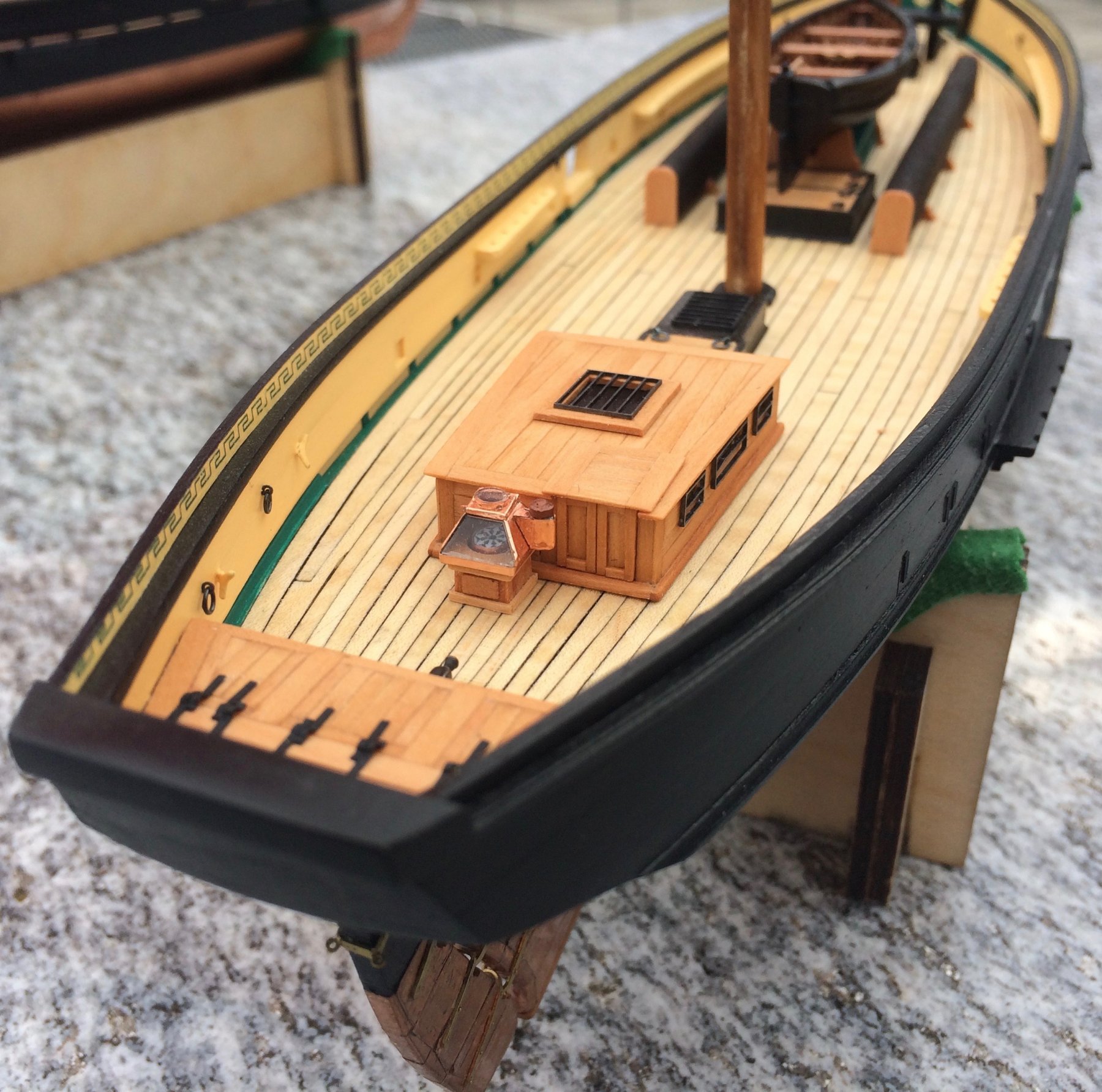
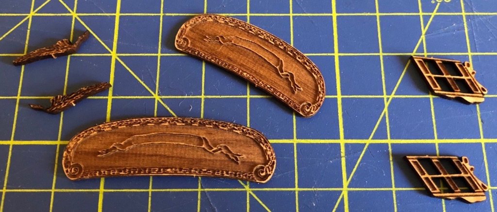
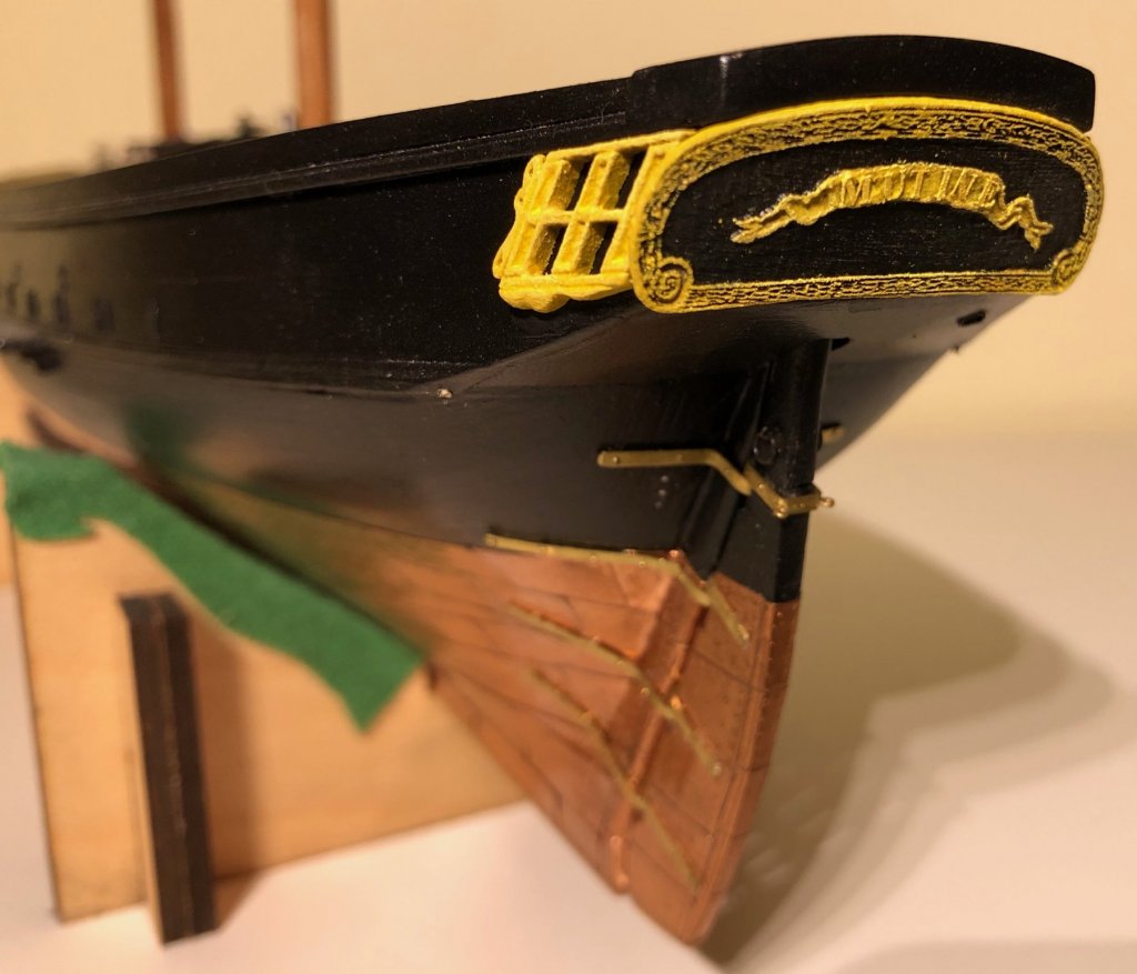
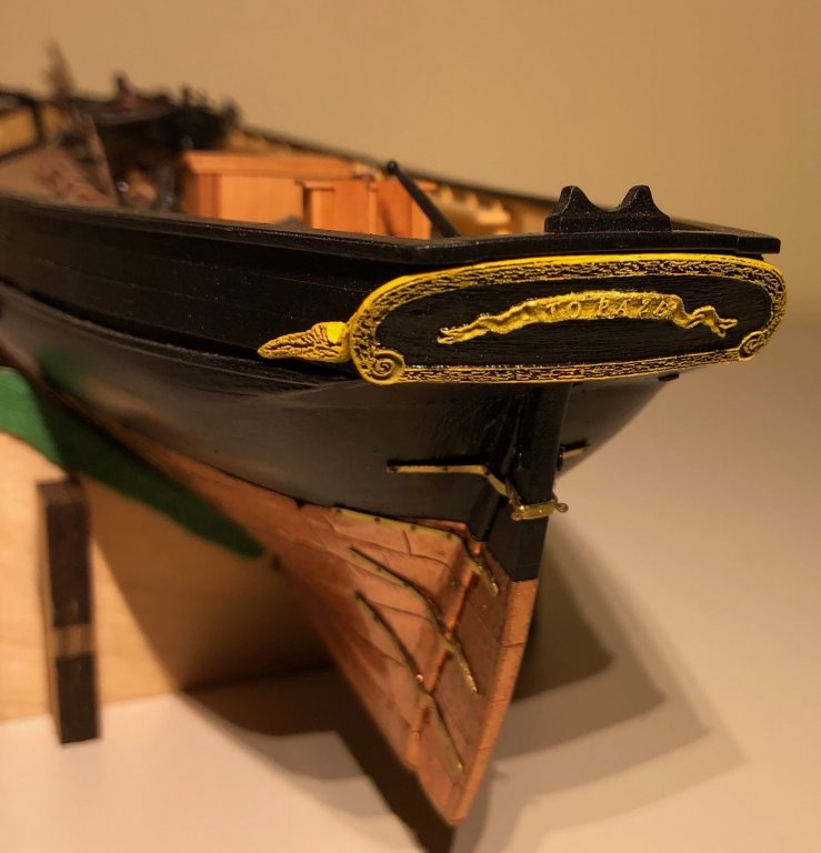
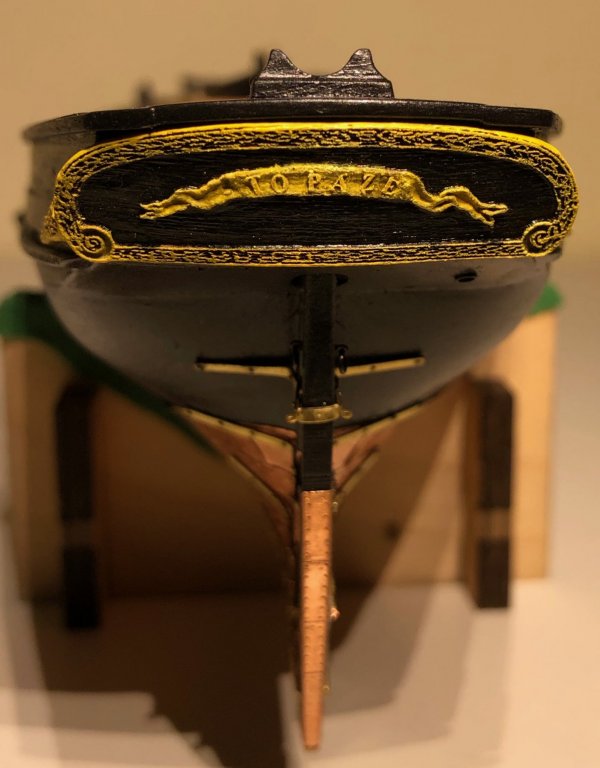
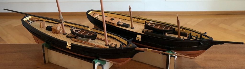
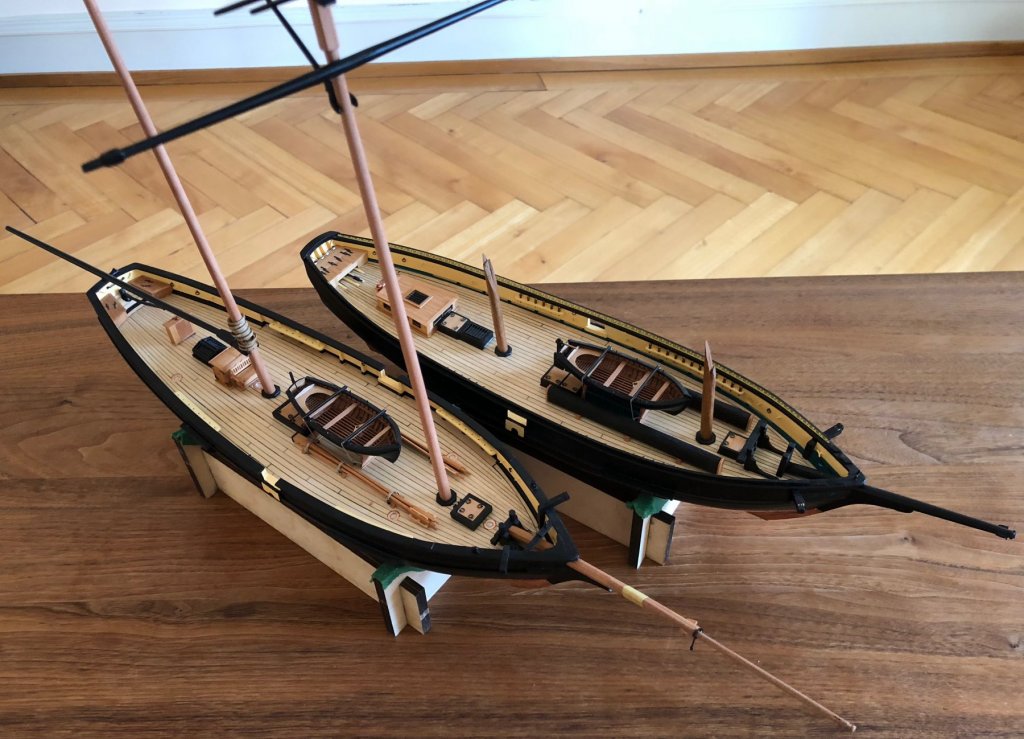
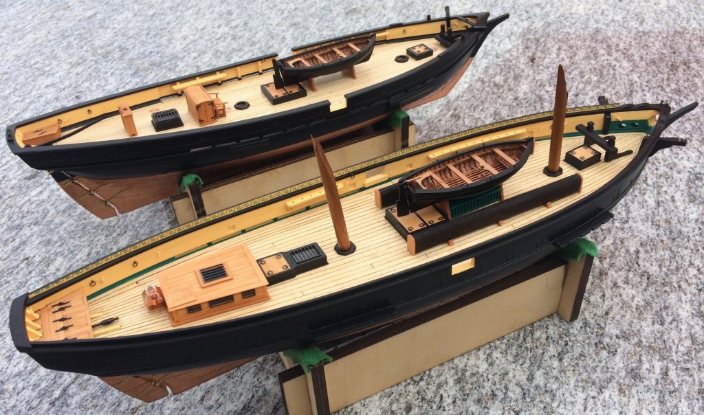
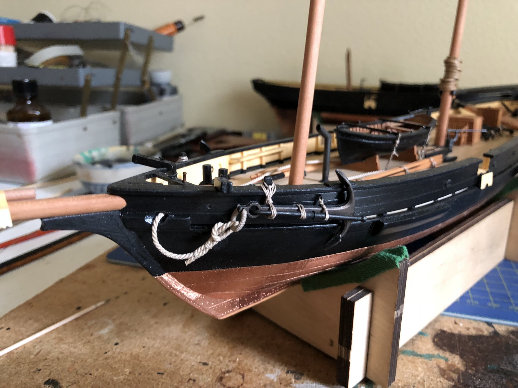
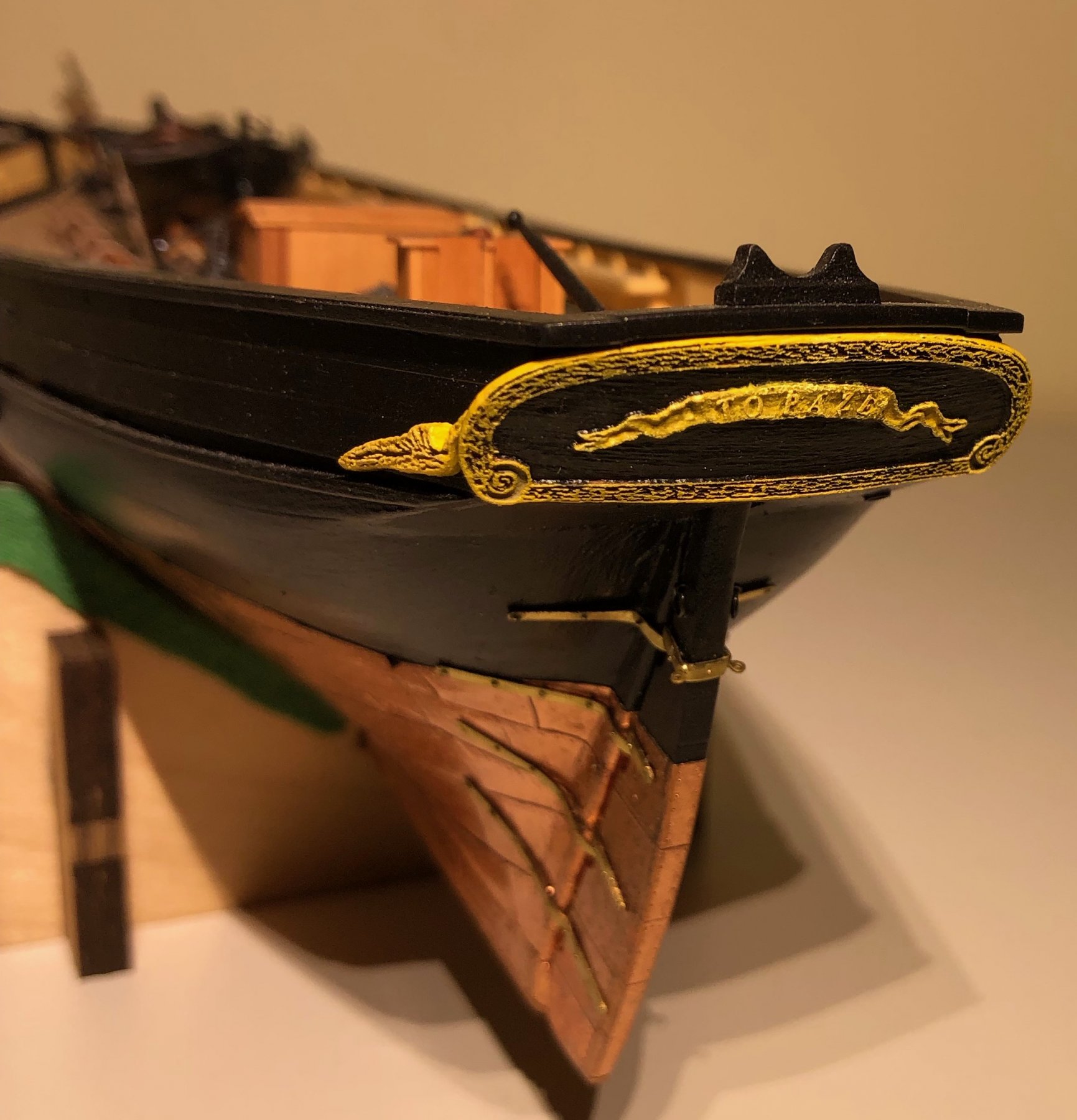
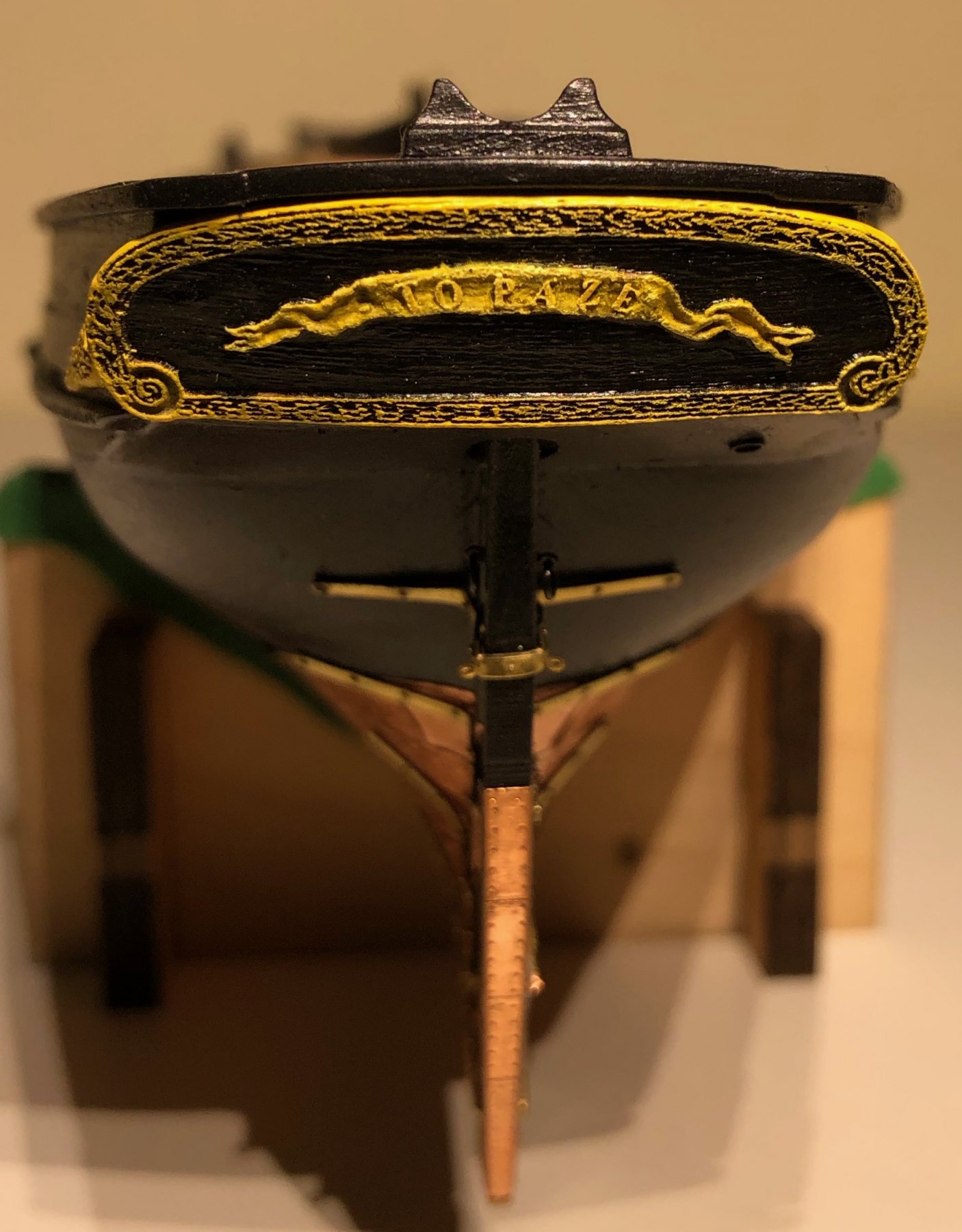
It has been almost a year since I updated my log. I even worked on another project: Still, some small details were added to my schooners. First and most important, my childhood dream: A wheel! While La Topaze only had a tiller, La Mutine had a real wheel fitted. If I were to speculate, the reason for this might be found in the heavy rigging. La Mutine was probably much harder to steer than the sweetsailing Topaze (as trials in 1823 have shown). Iron pumps and stoves followed (only a chimney in the case of La Topaze). La Topaze got her anchors. And then, finally, both got their names! Carving failed, so I had to search for another method. I experimented with laser cutting, added putty, paint and metal letters (1.5mm). Gregor


- 121 replies
-
- 20
-
-
- la jacinthe
- schooner
- (and 2 more)
-
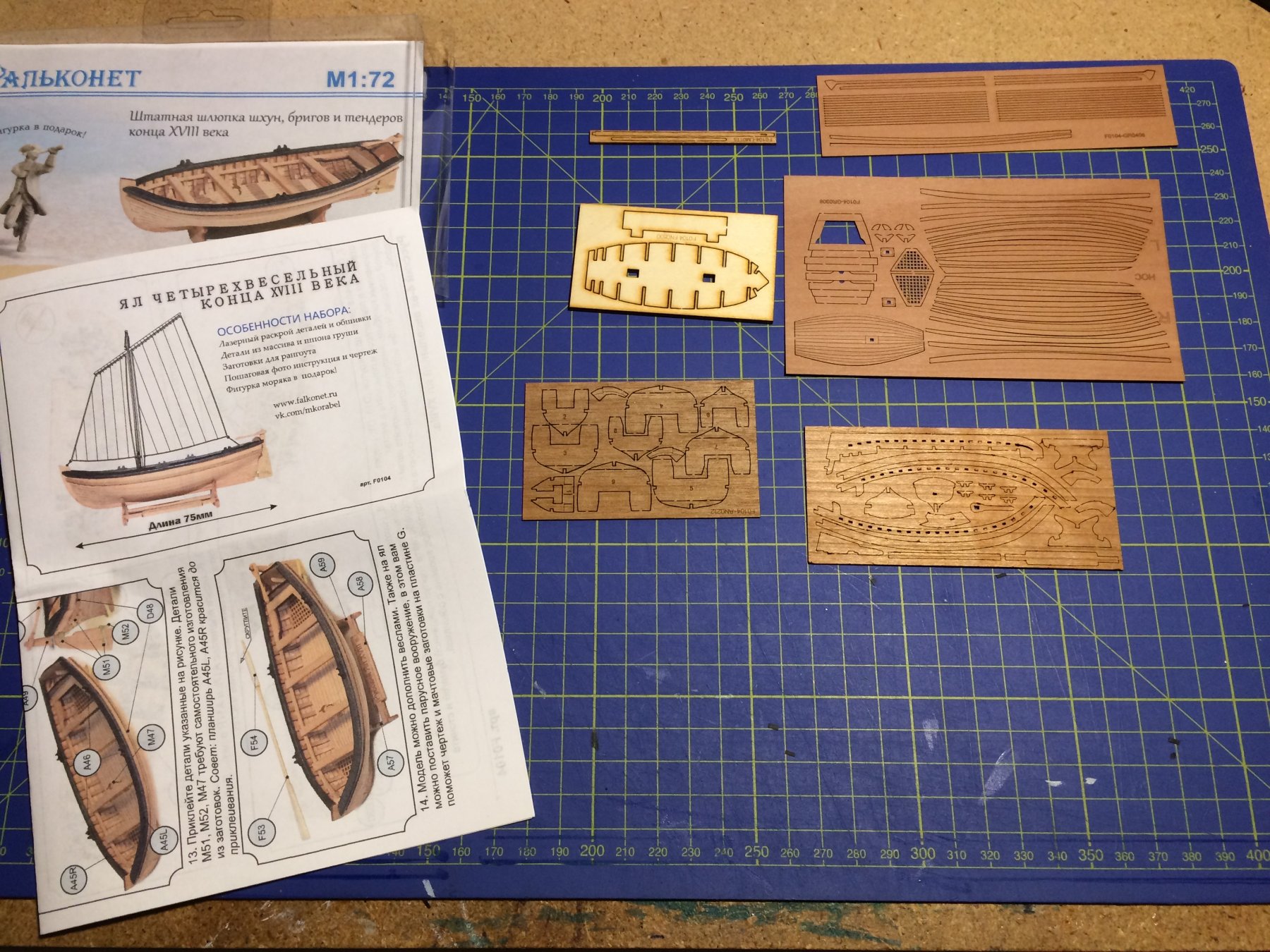
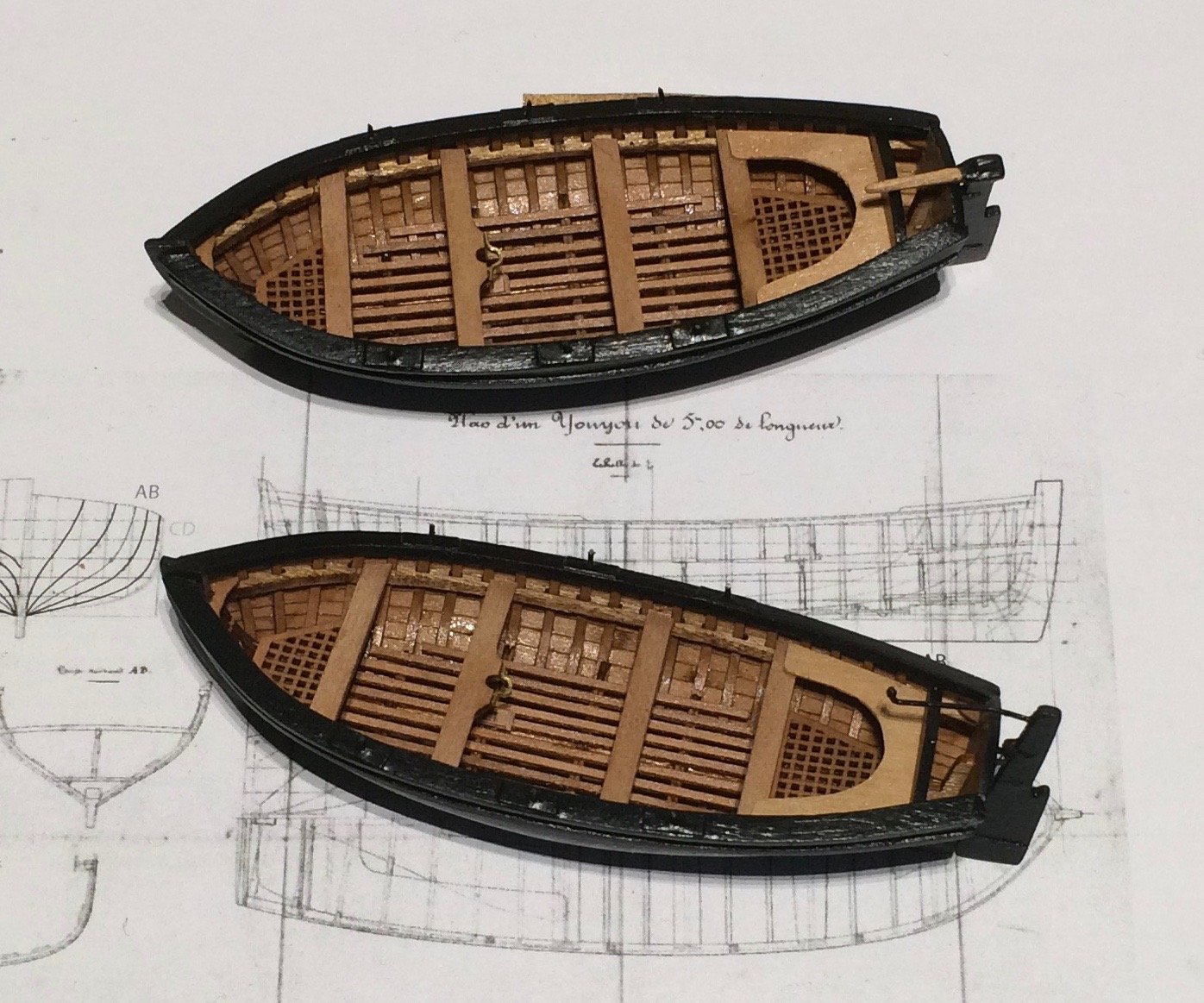
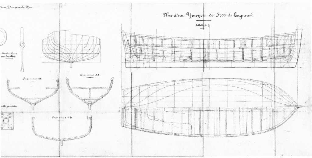
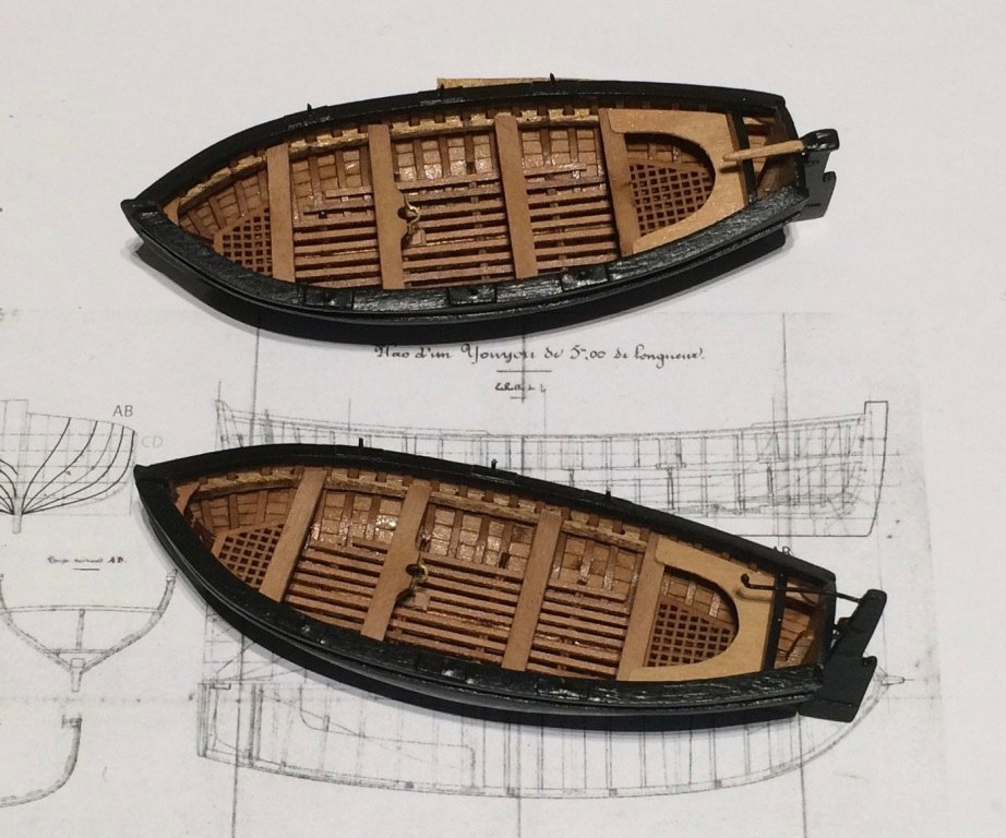
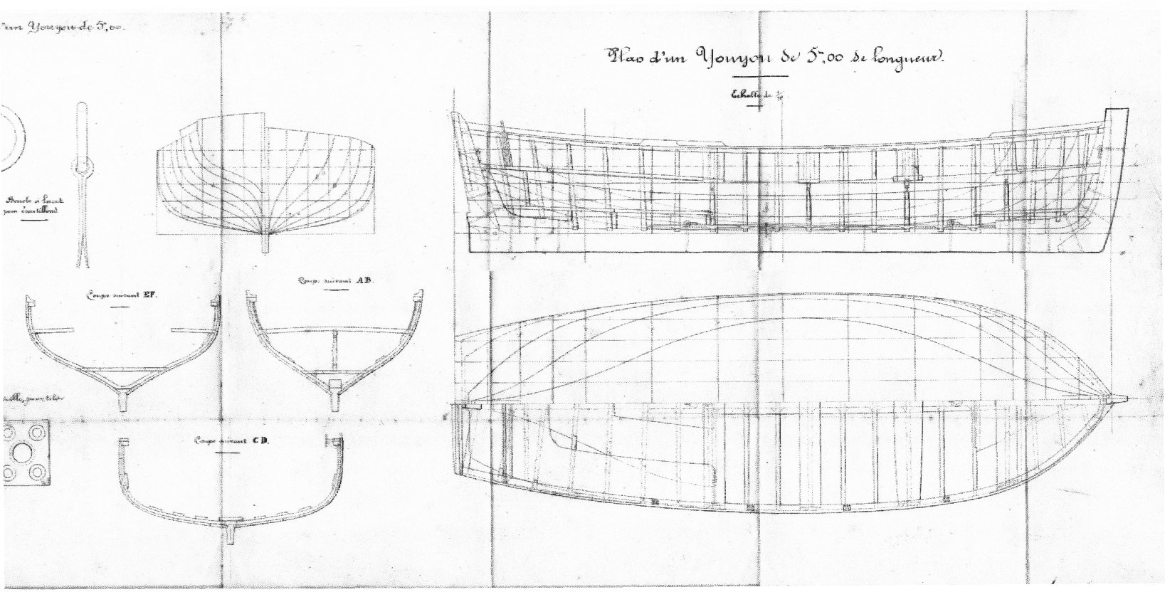
Hi aviaamator My small cutter was a kit (http://www.falkonet.ru/boat2). With a little tweaking I made it look like a French boat called Youyou ("little darling") of 5 meters. I followed the tip of French modeler Bruno Orsel, who sent me the plan (sorry about the quality) he found in a French archive. Boudriot's drawing shows a bigger cutter of 6 (or 6.5) meters, as shown in the Atlas du Génie maritime, page 119. source: https://web.archive.org/web/20120113075641/http://www.servicehistorique.sga.defense.gouv.fr/02fonds-collections/banquedocuments/planbato/atlas/rec.php
119.thumb.jpg.8eff33d4a00f87cb8a16aea28258e61f.jpg)
- 121 replies
-
- 4
-
-

-
- la jacinthe
- schooner
- (and 2 more)
-
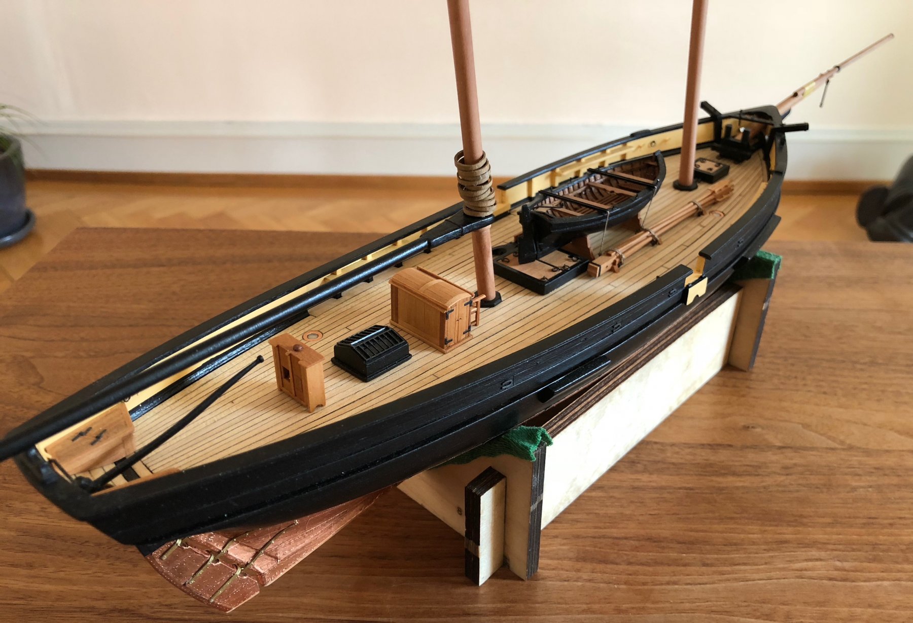
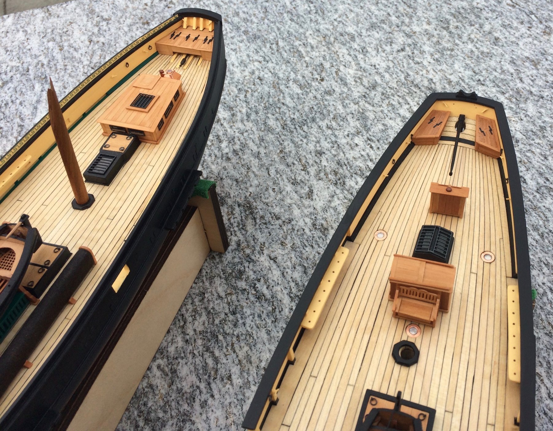
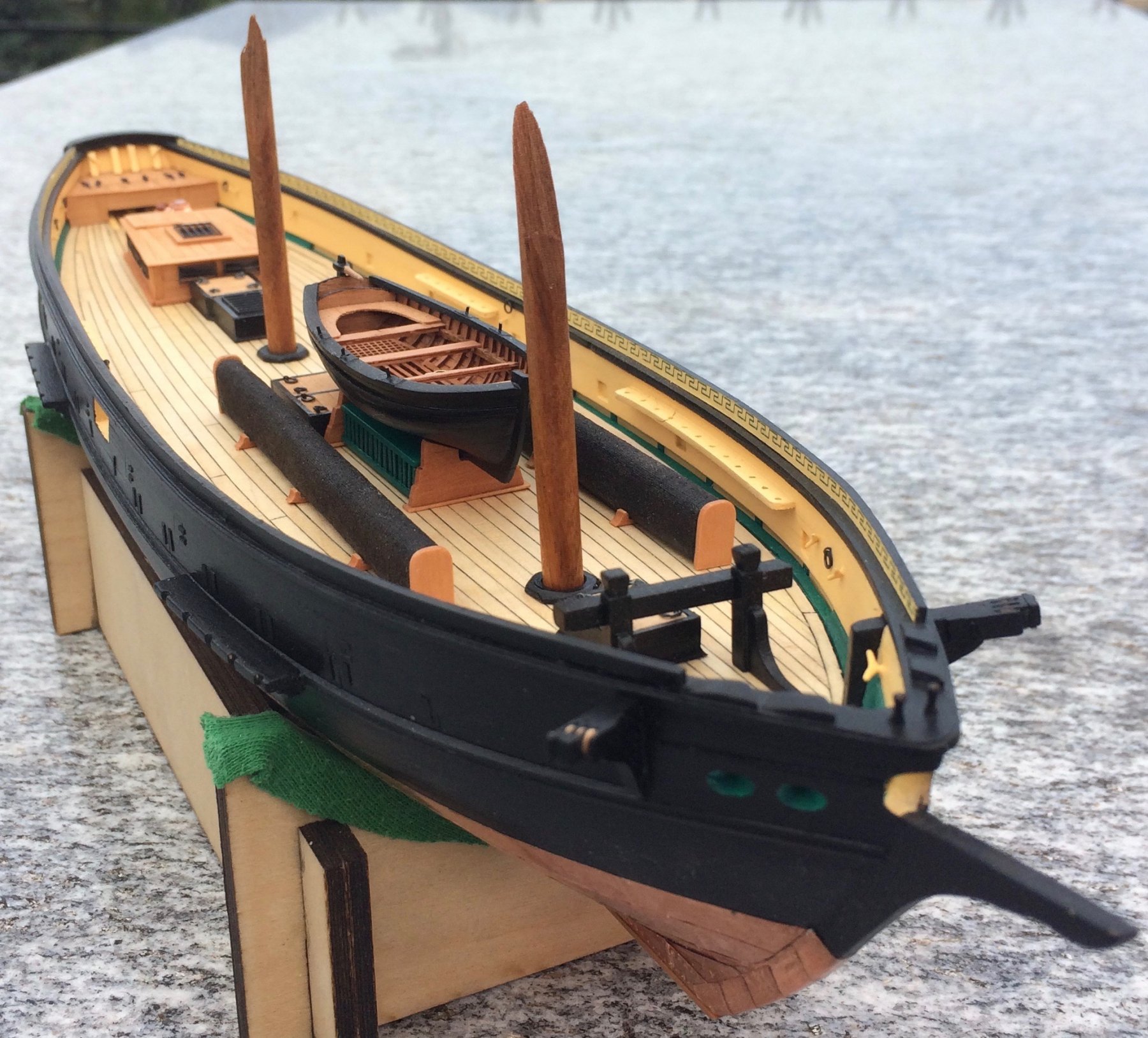
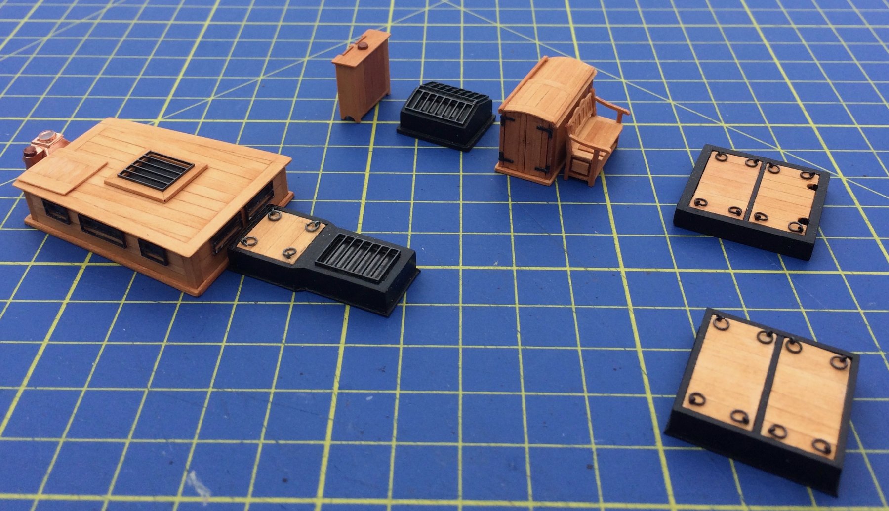
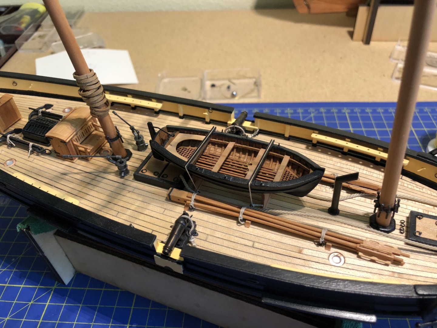
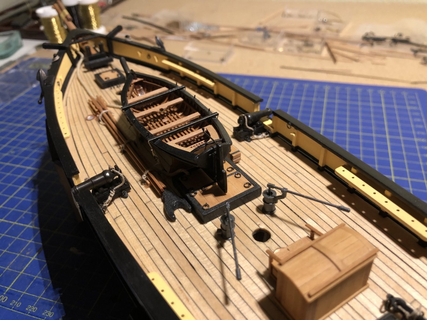
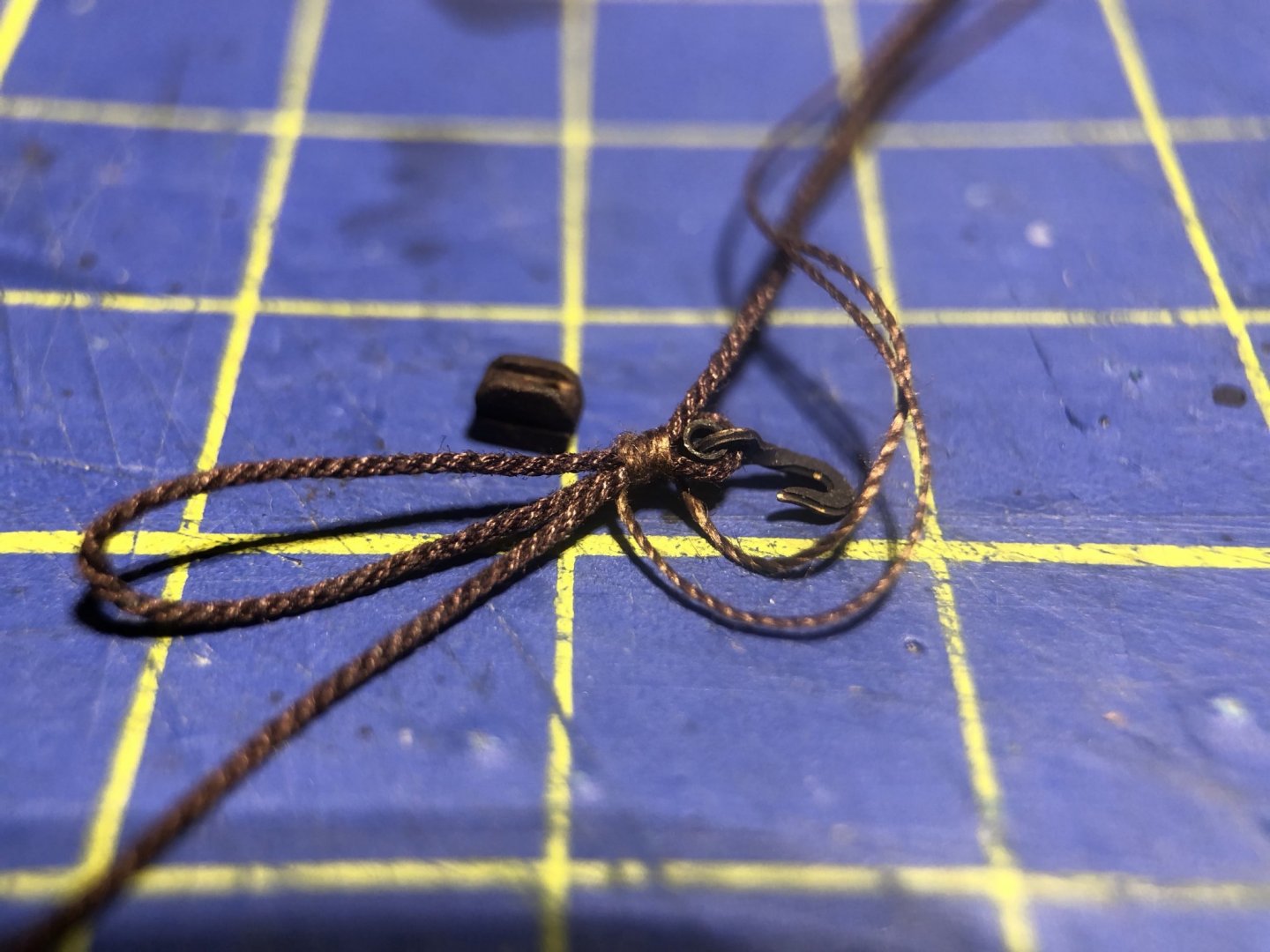
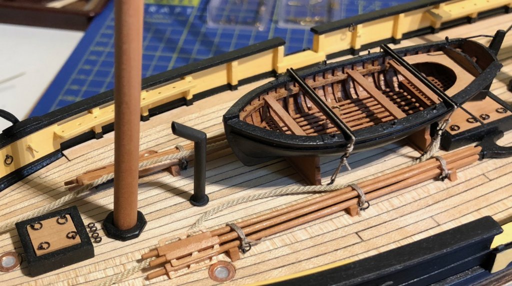
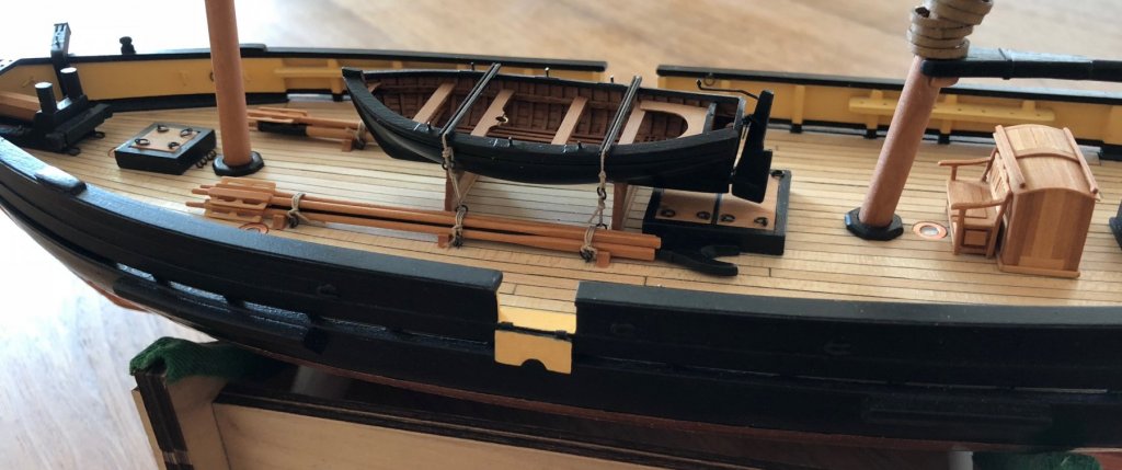
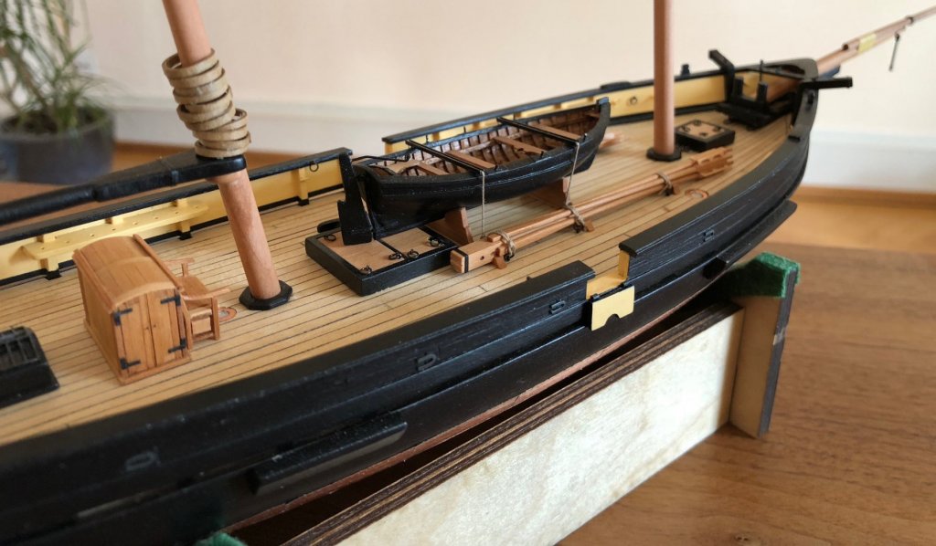
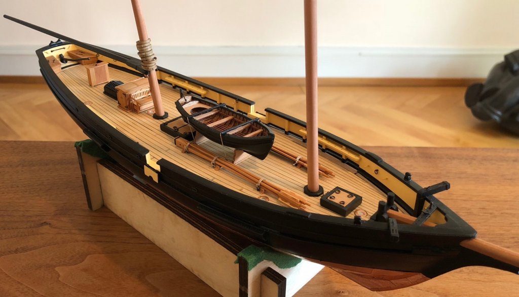
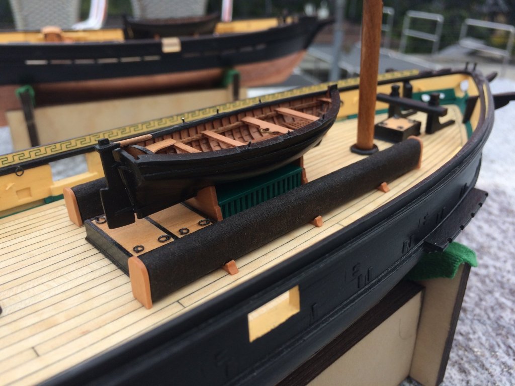
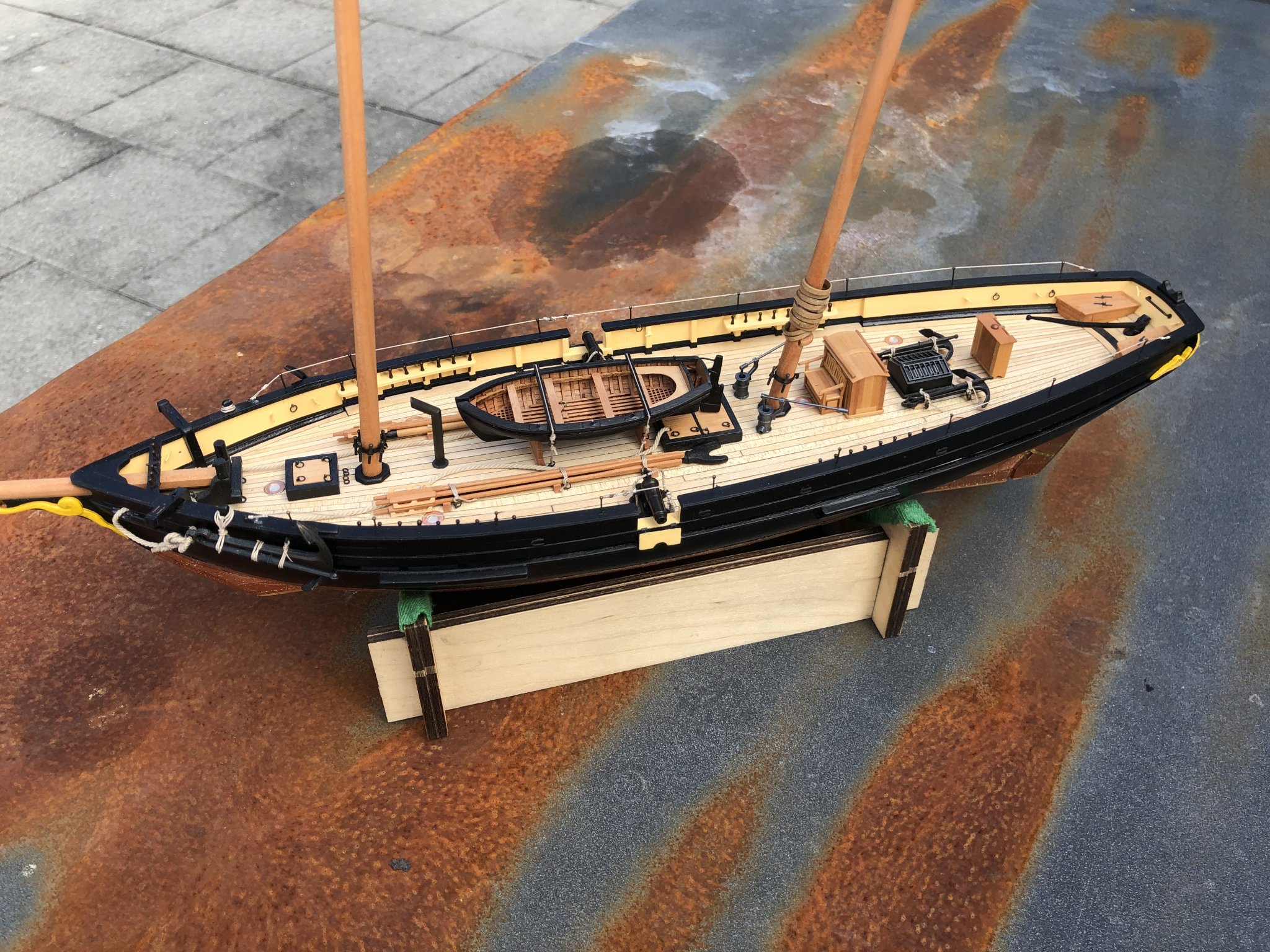
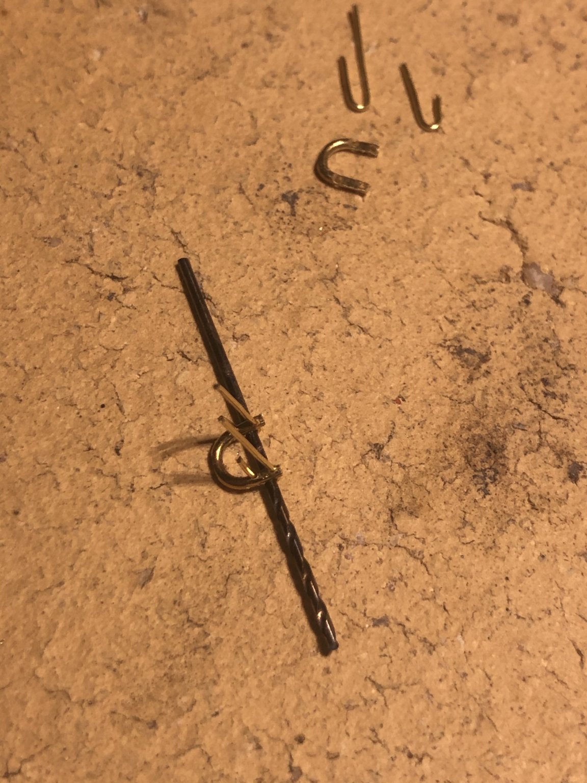
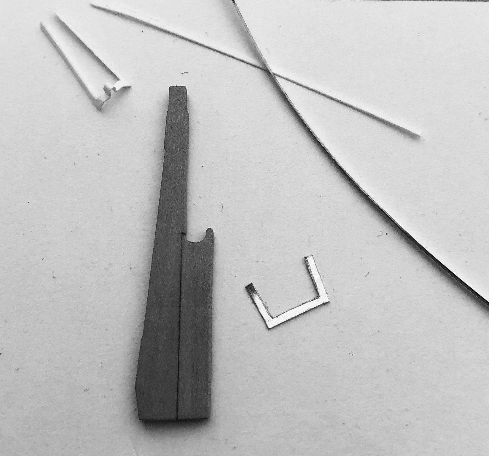
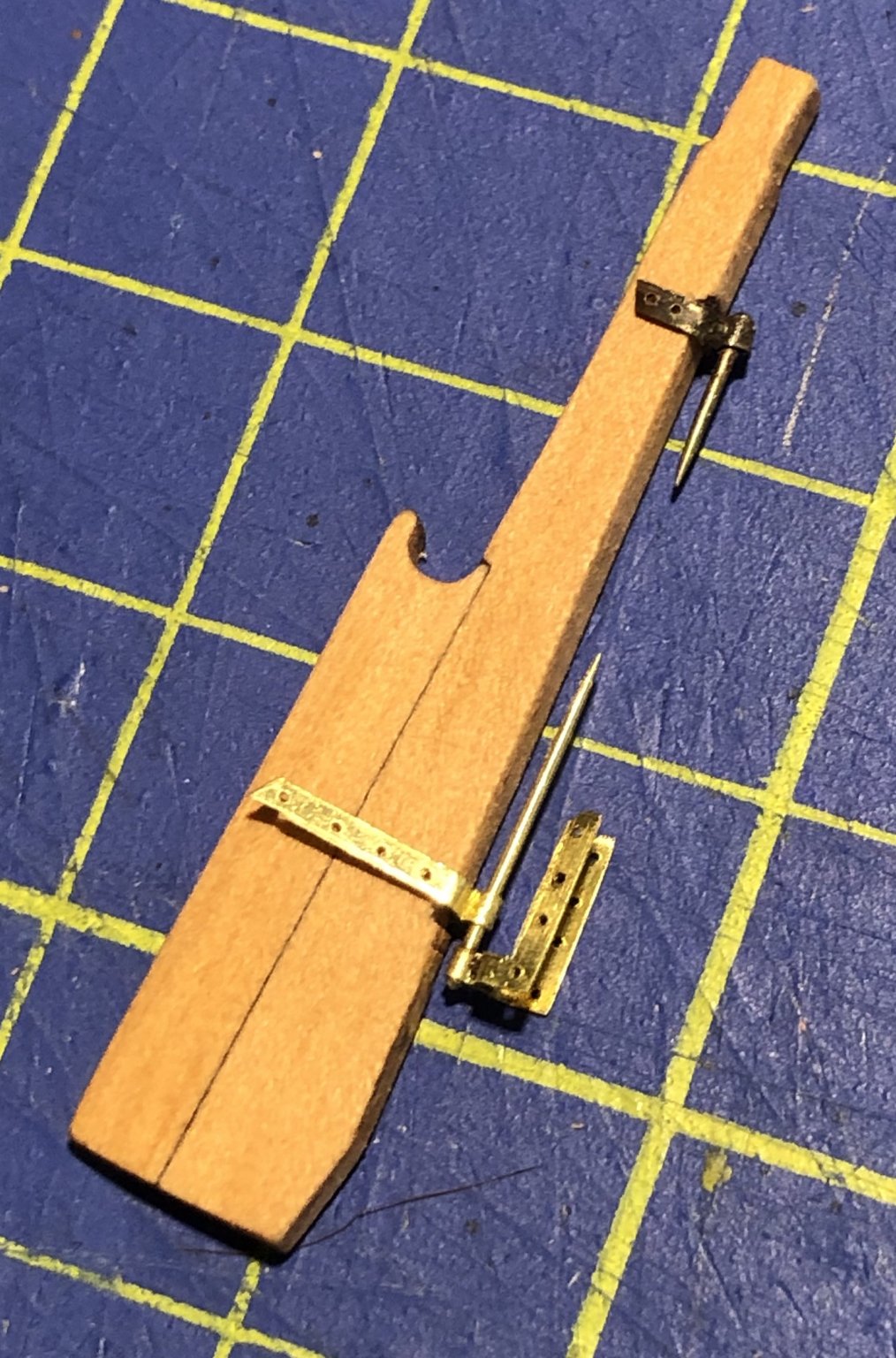
As La Topaze has no cover for her spars and oars, I had to make them in order to lash them down beside the cutter – so I made the complete set. There are still some details missing (pumps, decorations). But the next step will be a simple one: a chimney for Topaze’s galley. I wish you all a happy New Year! Gregor


- 121 replies
-
- 20
-
-
- la jacinthe
- schooner
- (and 2 more)
-
I even added some details I dreamed up: You can find covered spars and oars in bigger, contemporary ships like La Créole (plans G. Boudriot), and animal cages under the small cutter. So that’s my gift to the Mutine for her next voyage to the Indian Ocean.
- 121 replies
-
- 11
-
-
- la jacinthe
- schooner
- (and 2 more)
-
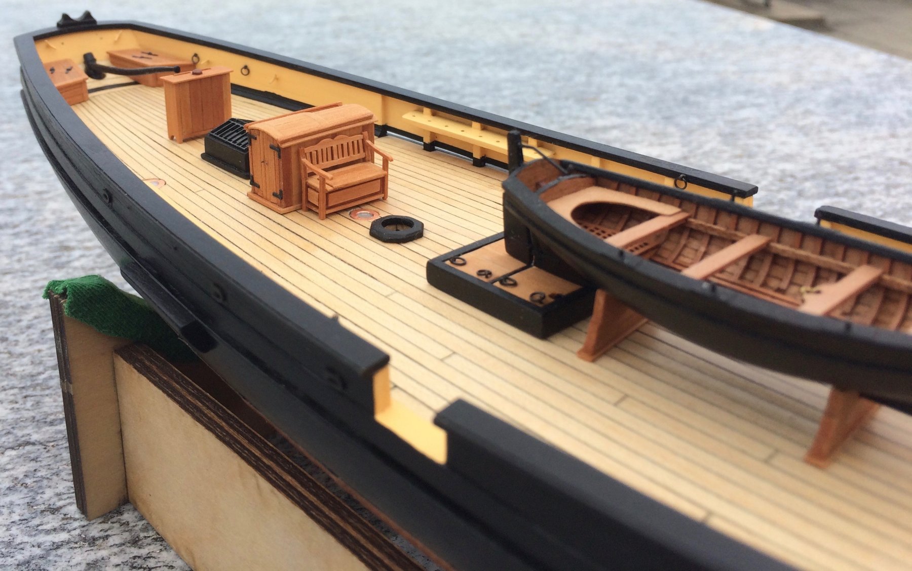
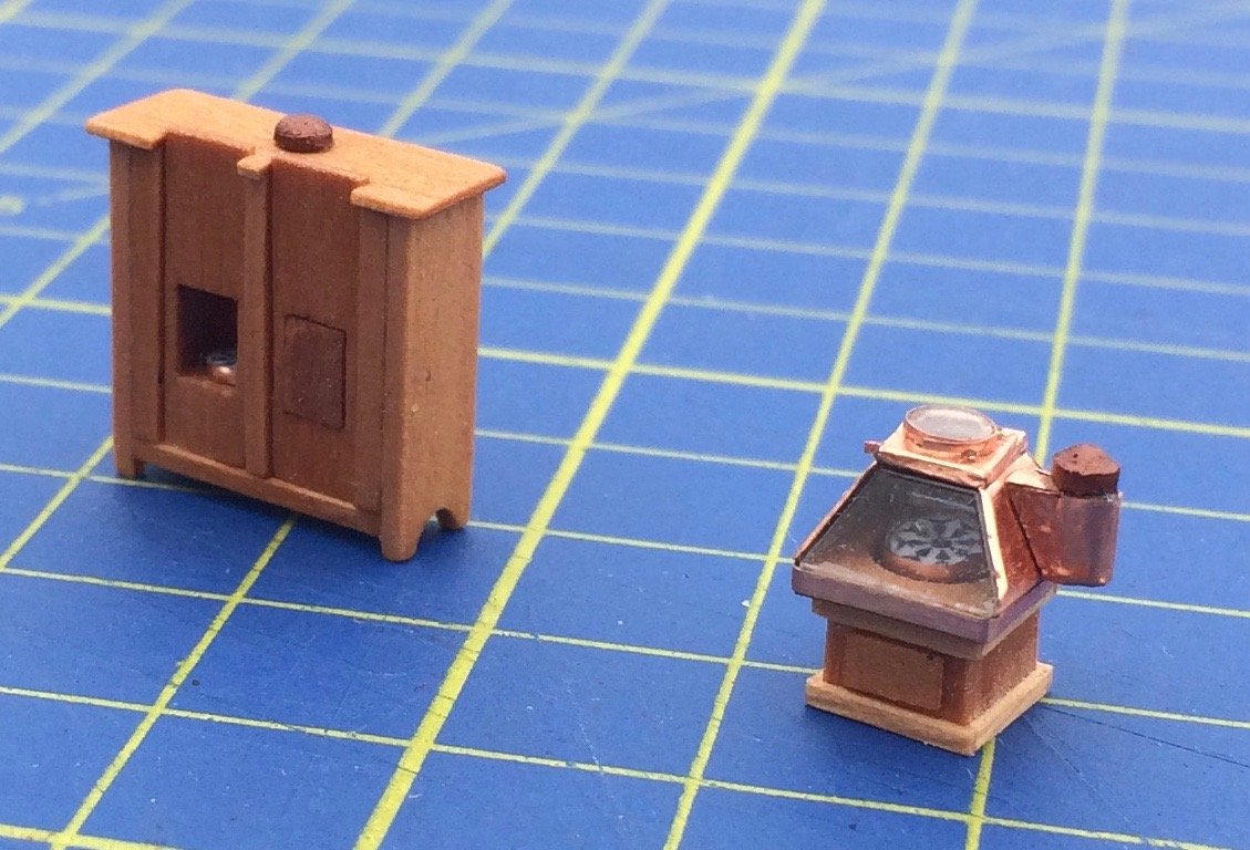
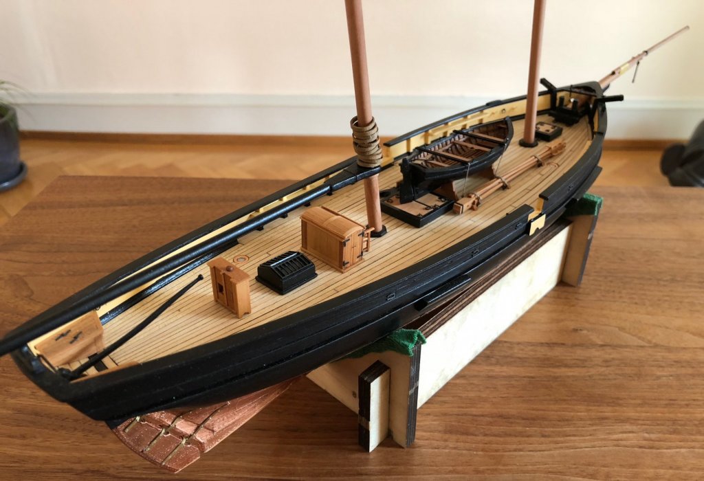
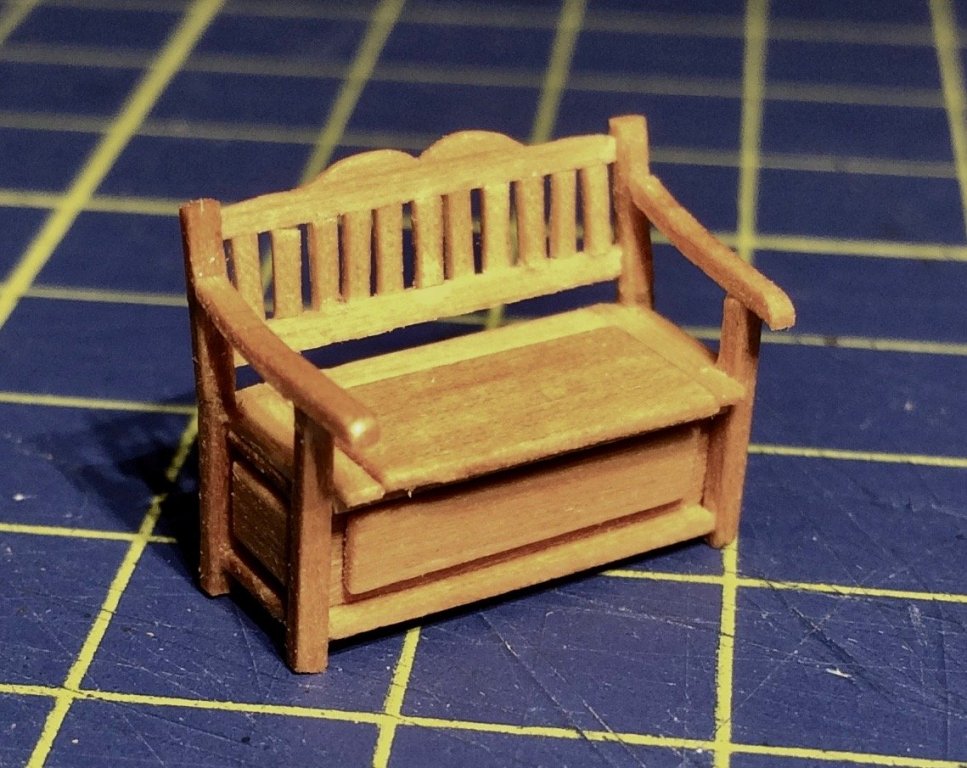
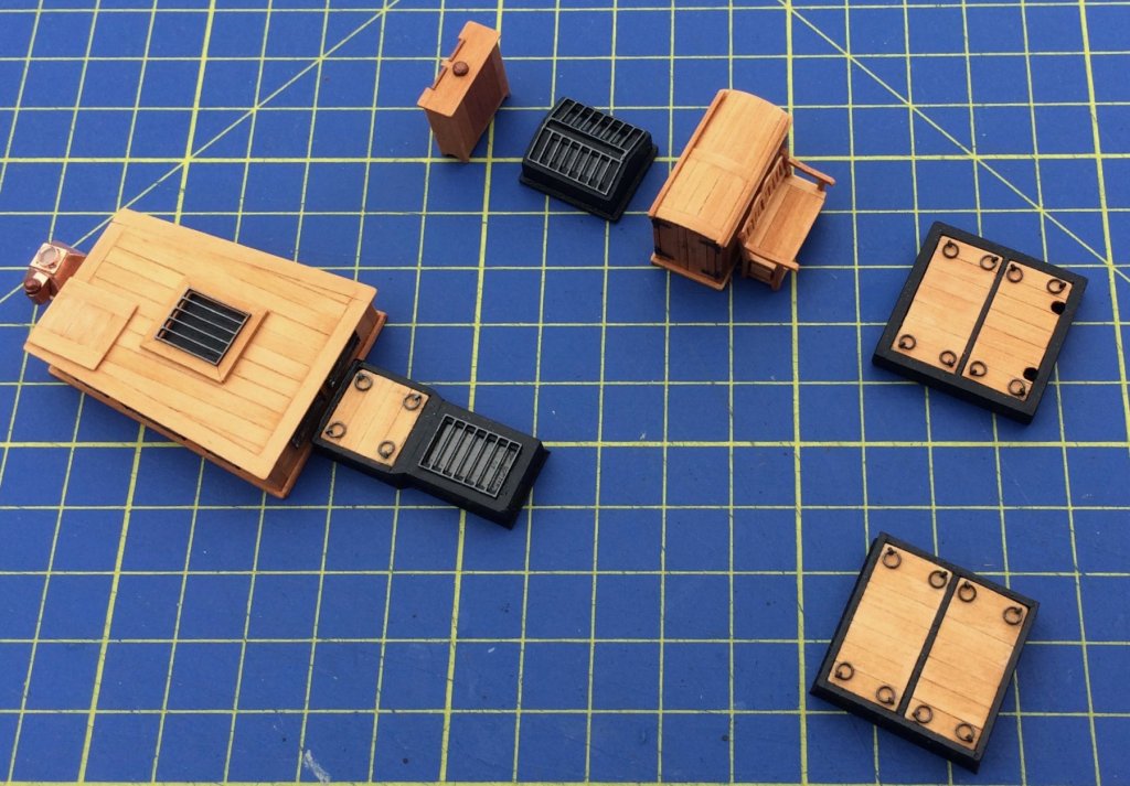
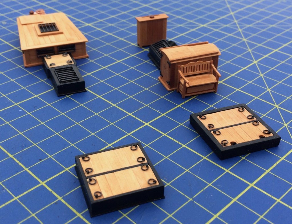
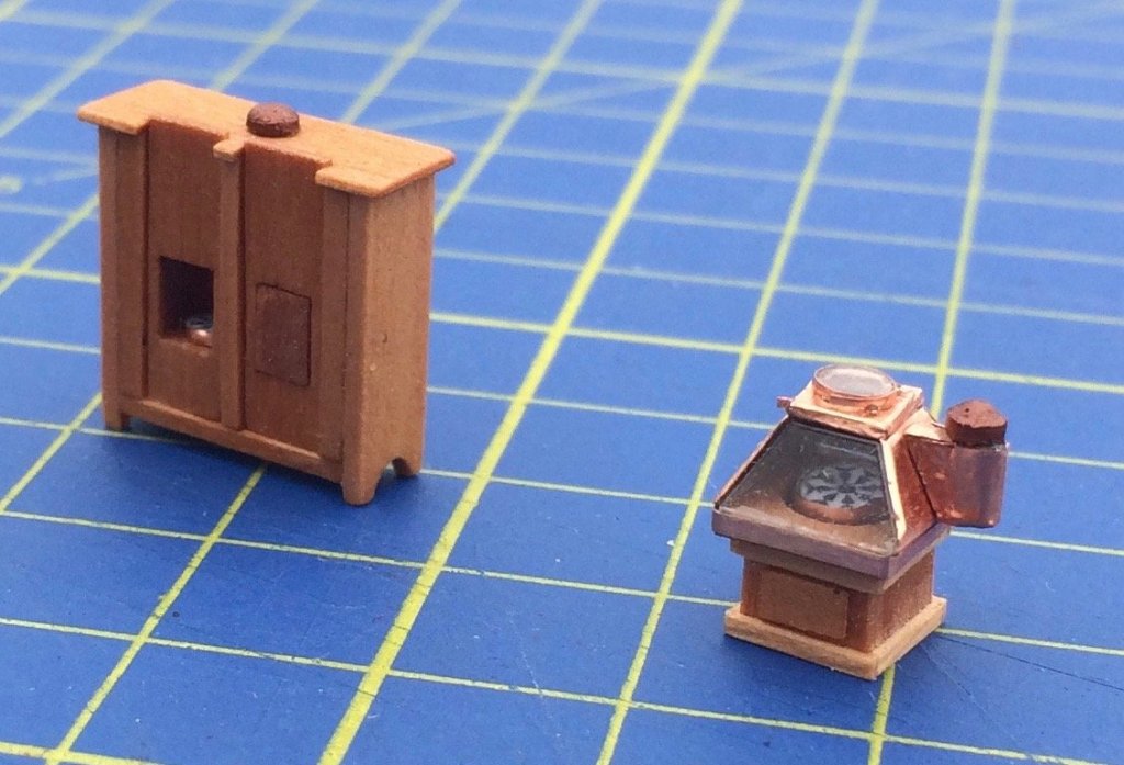
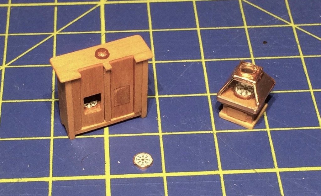
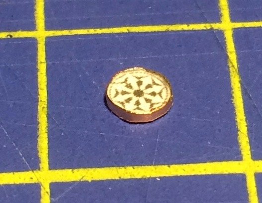
This bench for officers (quite typical in French ships) stands as a symbol of slow progress: But still, I managed to add a few details to my decks. A closer look: Both ships now have their binnacles: Topaze a very traditional one, Mutine the new, modern version. Topaze’s compass is 25cm in diameter, that of La Mutine 25, according to the Atlas du Génie maritime.


- 121 replies
-
- 18
-
-
- la jacinthe
- schooner
- (and 2 more)
-
Small stuff: a standard compass of 20 cm in 1/64 is really fun!
- 121 replies
-
- 7
-
-
- la jacinthe
- schooner
- (and 2 more)
-
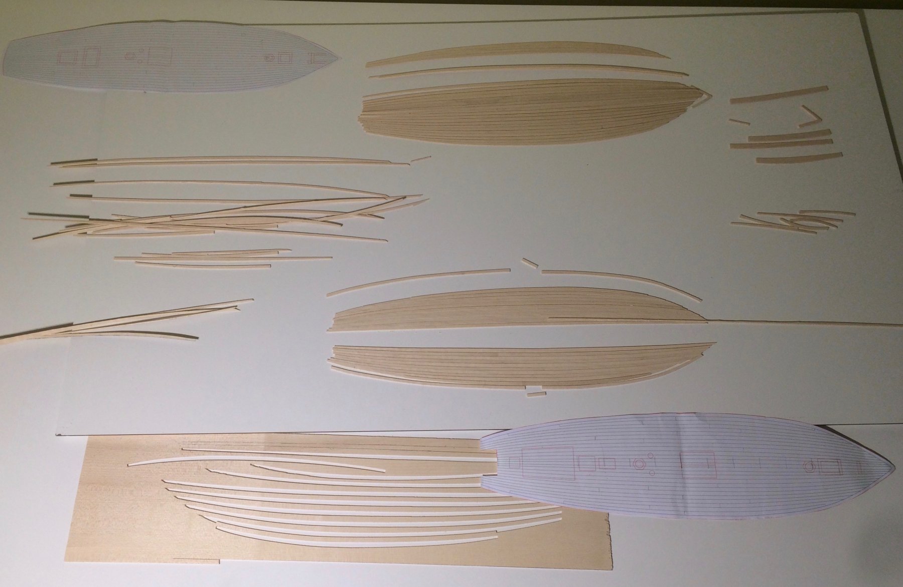
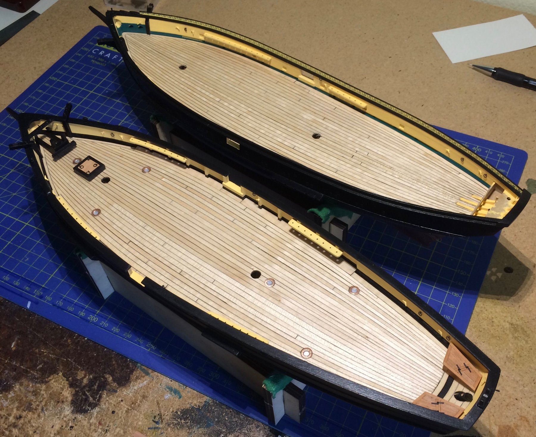
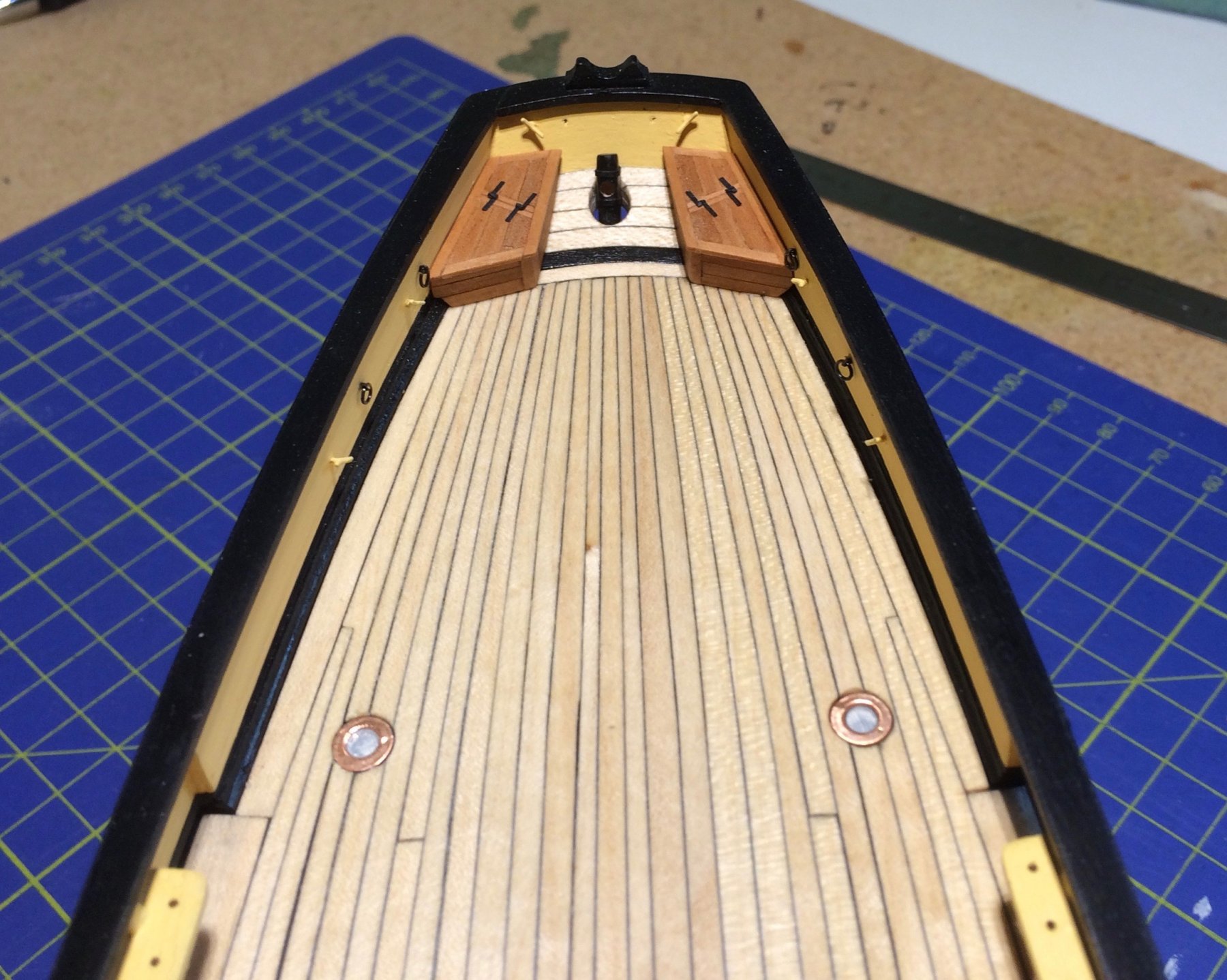
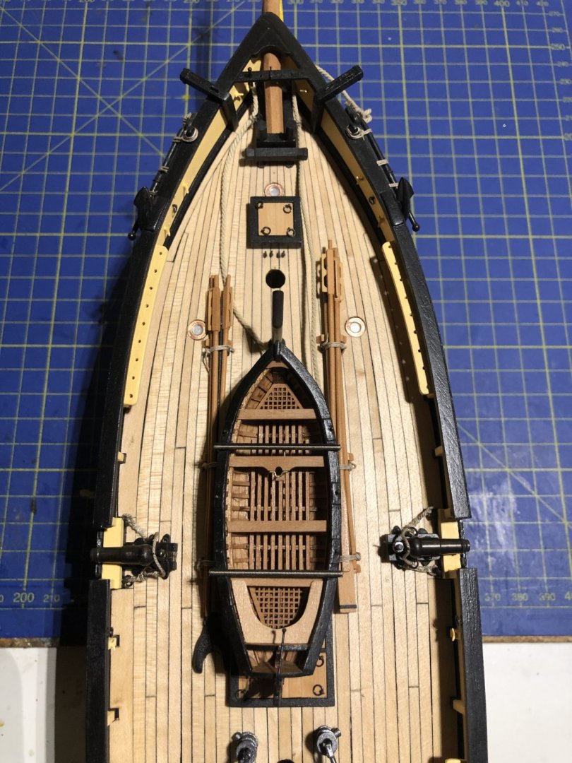
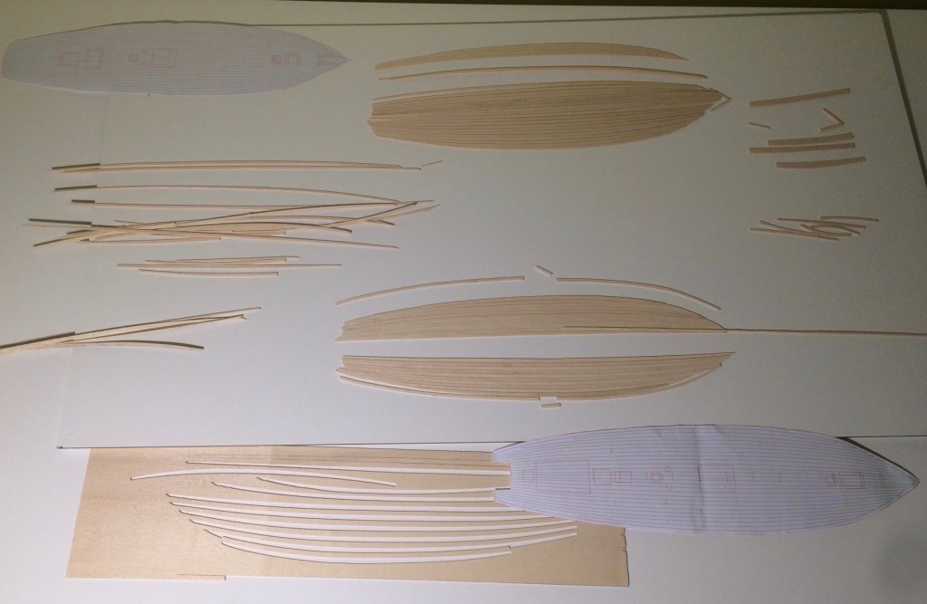
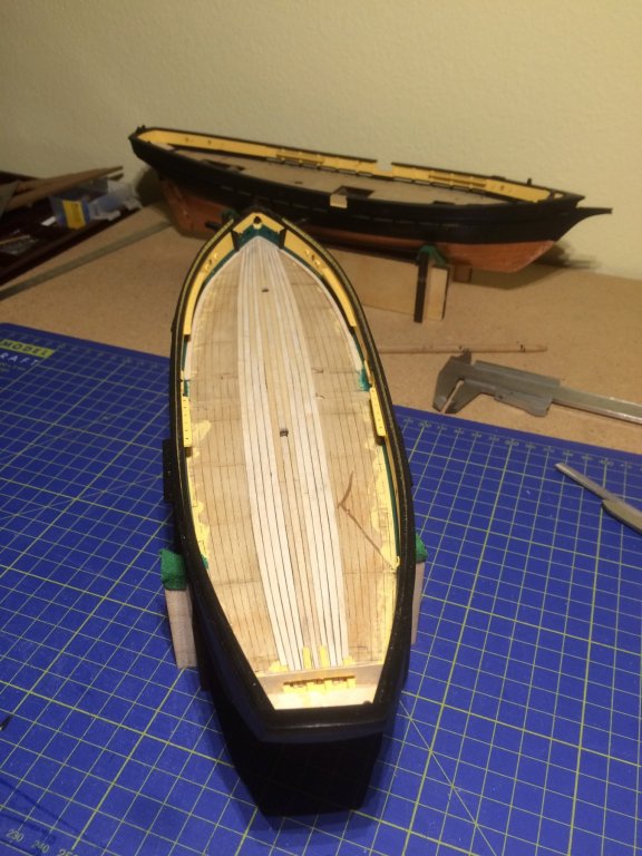
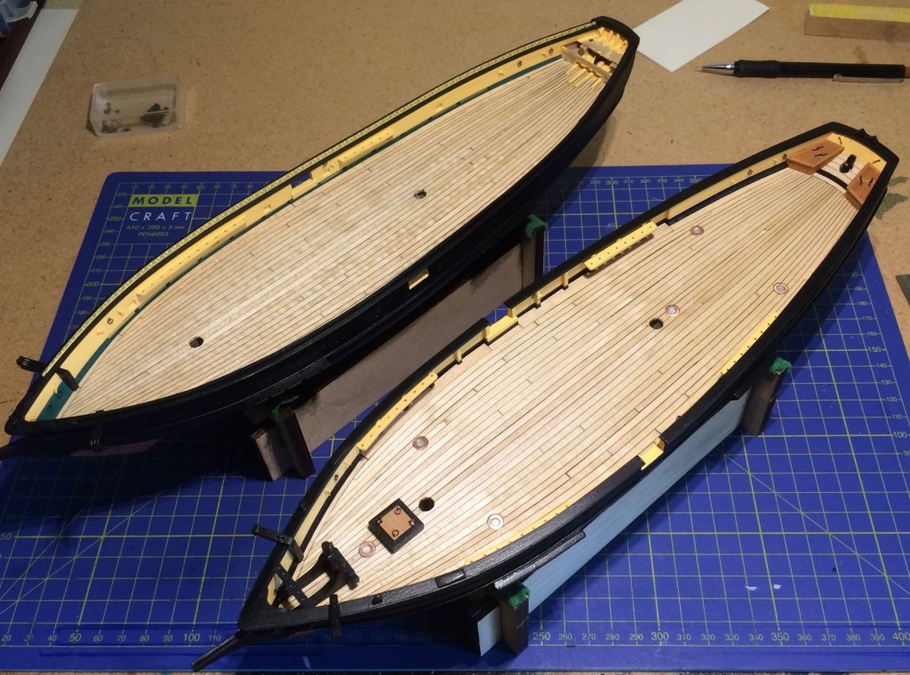
Thanks, Tony, you are very welcome! The planking of the decks was another, much bigger project that had me worried since autumn. There are no straight planks, all are curved. Also, it seemed that both the Mutine’s planking pattern and the model of the Topaze in Paris are different from the plans of Jean Boudriot’s Jacinthe. A friendly model train builder came to rescue. He owns a CNC-mill and cut my planks (I had to learn the differences between drawing graphics with AdobeIllustrator and a CAD-tool, much wood was used up because we had to learn the differences between plastic sheets and maple wood and so on). Caulking was done with a soft pencil. After gluing the planks to the false deck, I scraped the decks with micro slides (cut edged glass – dangerous for your fingers when breaking, bad for the deck when you are bleeding). The Topaze got her six portholes I had prepared in advance. And now I’m looking forward to build all the small stuff you find on deck. Cheers, Gregor


- 121 replies
-
- 10
-
-
- la jacinthe
- schooner
- (and 2 more)
-
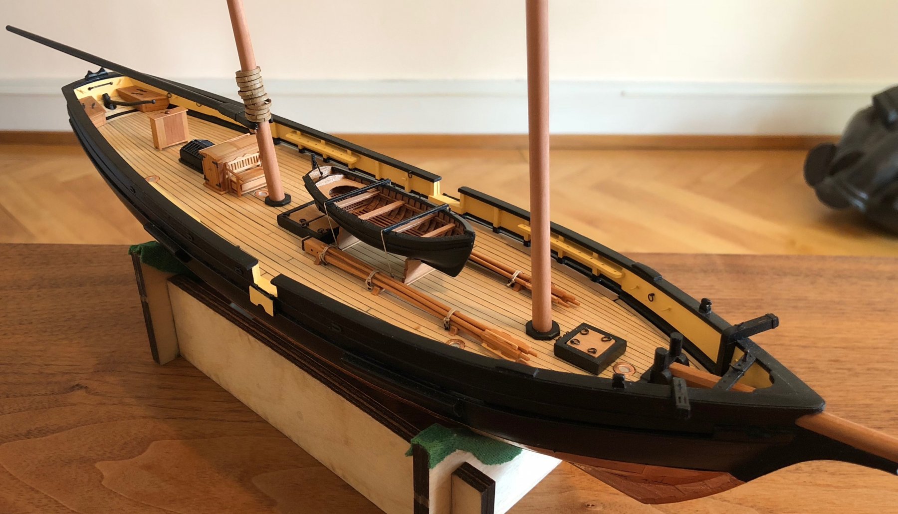
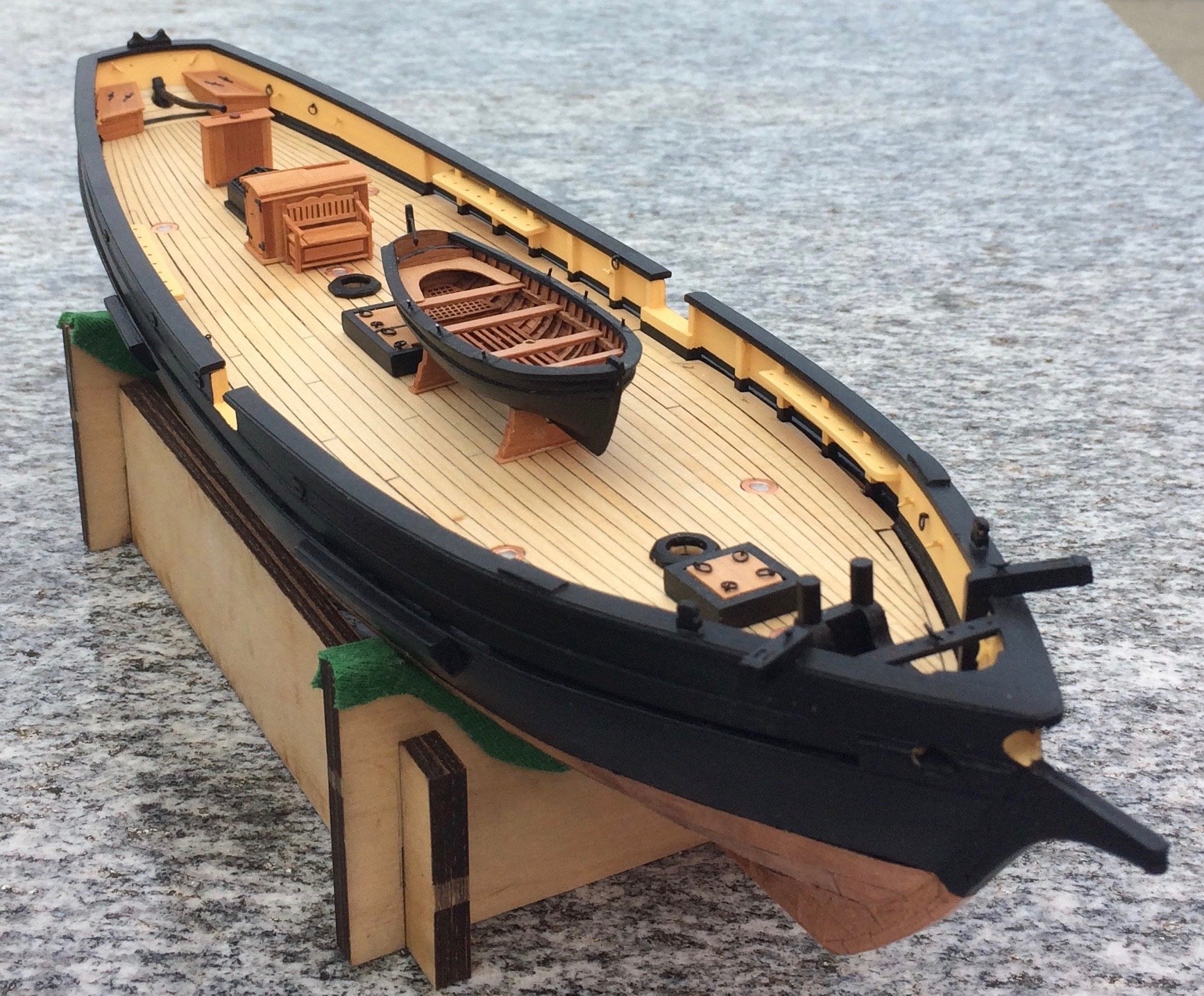
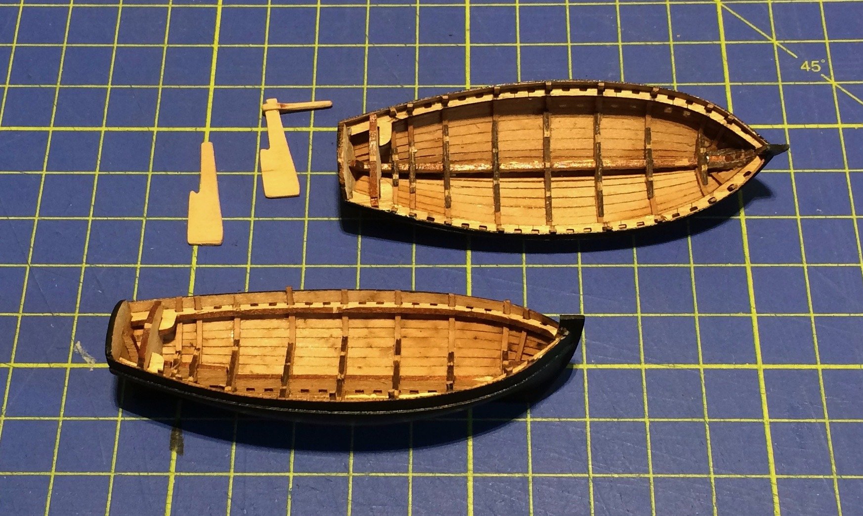
With a bad conscience, finally an update on my project. It’s slow going anyway, but some headway was made. After both hulls were coppered, I embarked on a small holyday project: the cutters. Jean Boudriot shows on his plans a cutter of 6.5 meters (“petit canot” in French). The maker of the Topaze model I’m copying in smaller scale proposed a smaller boat of 5.5 meters, based on his research. In French, it’s called “Youyou”, which translates in something like “little darling” or other nice things you would call a baby. I even started by cutting out the bulkheads when I discovered a nice little kit, made in Russia by Falconet (http://www.falkonet.ru/boat2). It has exactly the dimensions of my Youyou, and very easy to build (excellent explanations with enough pictures so you don’t have to understand Russian, which I don’t). But this is a scratch building log, so I made a semi-scratch French Youyou out of a Russion cutter. A cut at the stem and an addition at the stern gives a new silhouette, new rudders were made, benches altered, and after some other small changes I had two French boats as used in the 19th century. The little kits, by the way, are cleverly done, the planks are laser cut and perfectly fitting, the pear wood in excellent quality. That’s it for the moment, another entry will soon describe the planking of the decks. Gregor


- 121 replies
-
- 11
-
-
- la jacinthe
- schooner
- (and 2 more)
-
... then I'm glad I can offer more than one hull, to please the diverse tastes of my viewers! Gregor
- 121 replies
-
- 4
-
-
- la jacinthe
- schooner
- (and 2 more)
-
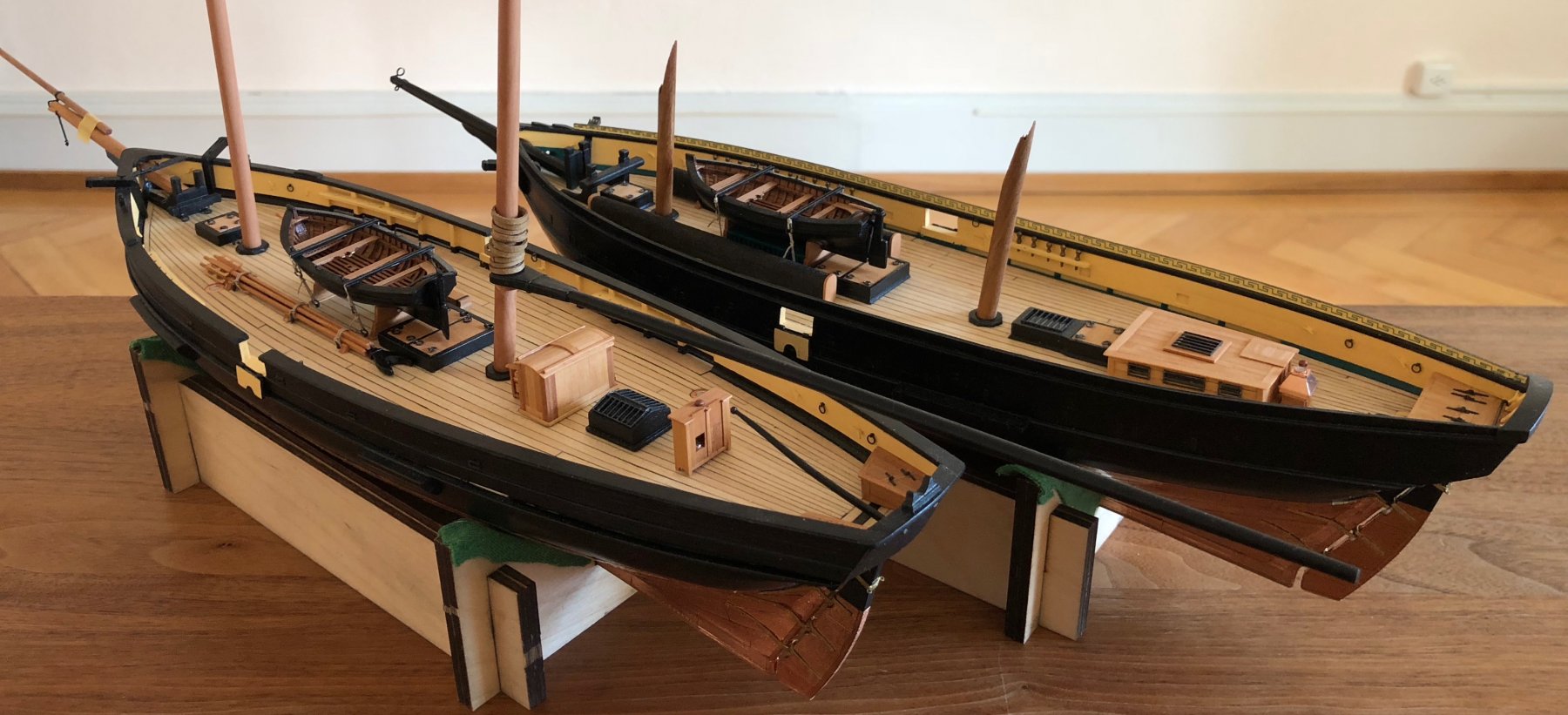
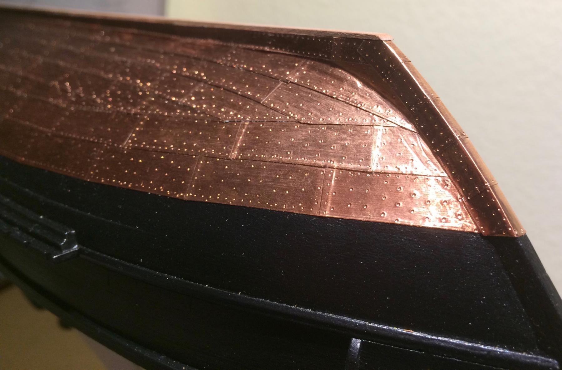
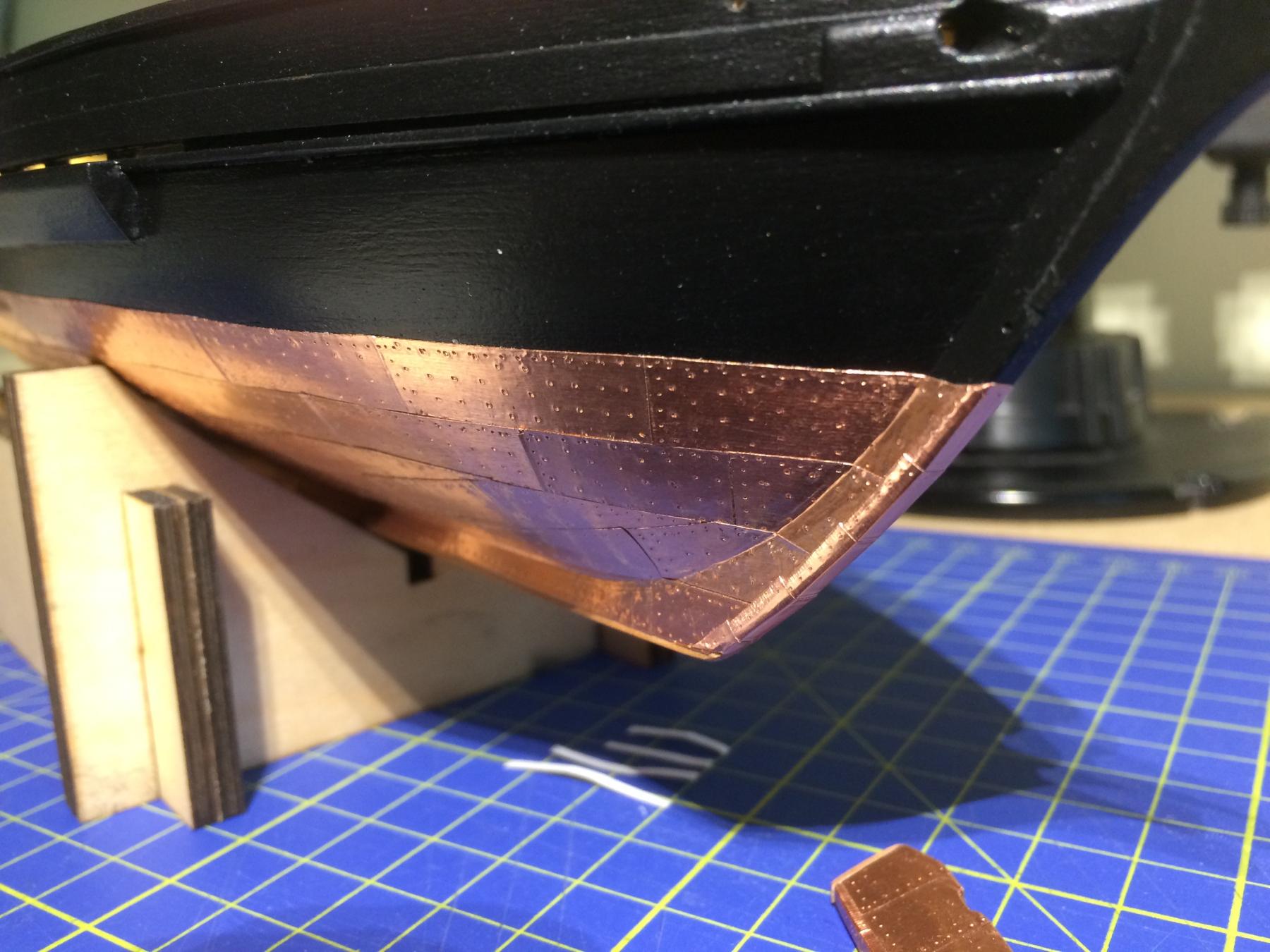
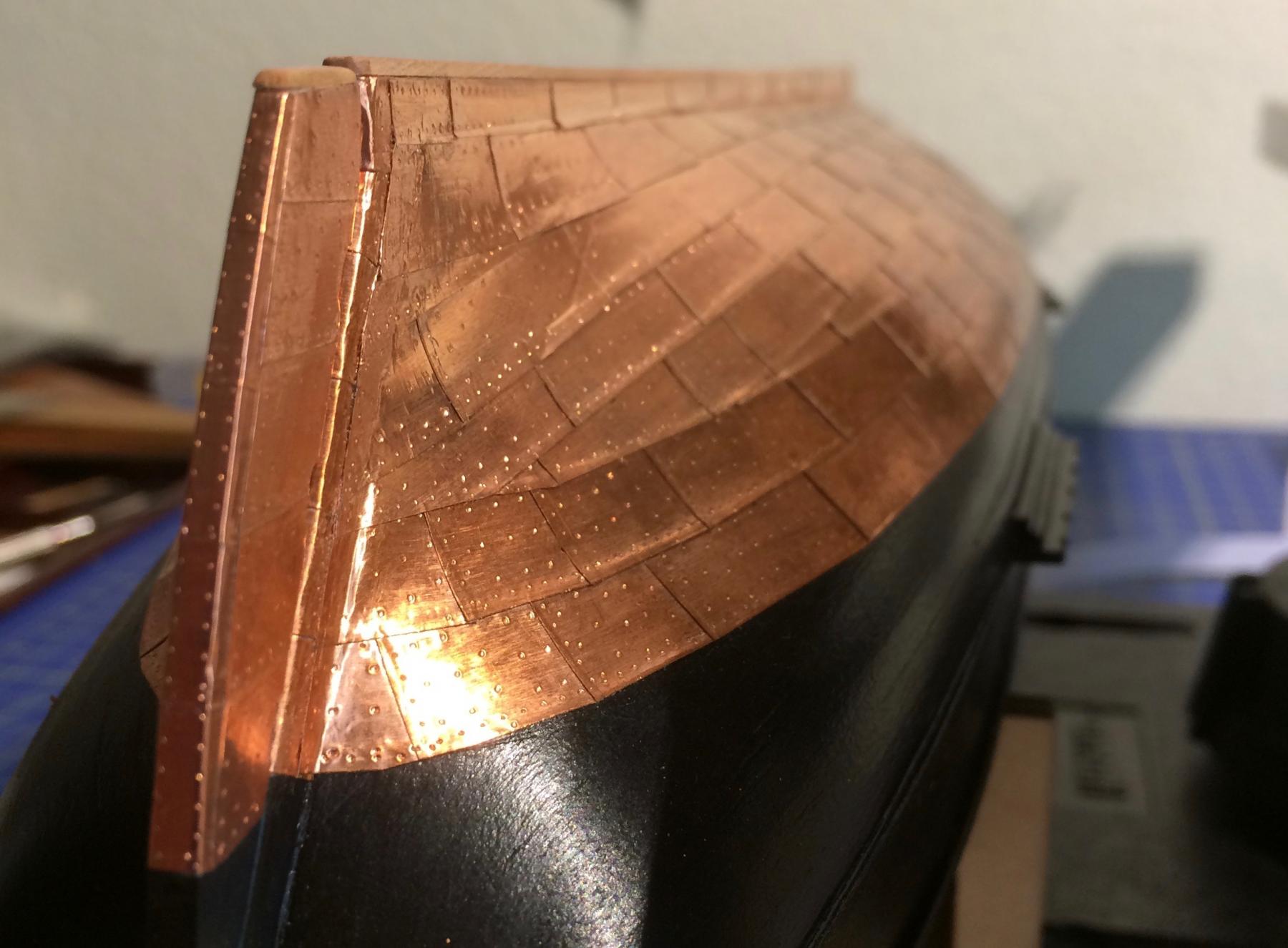
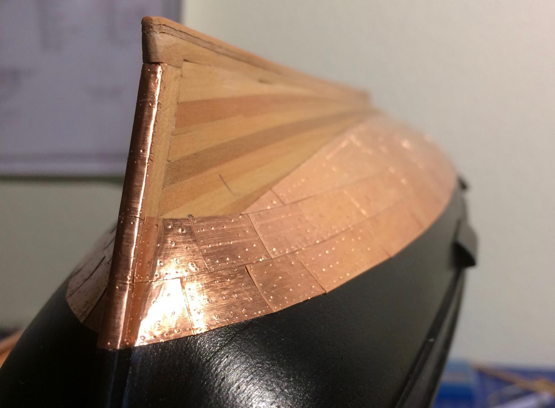
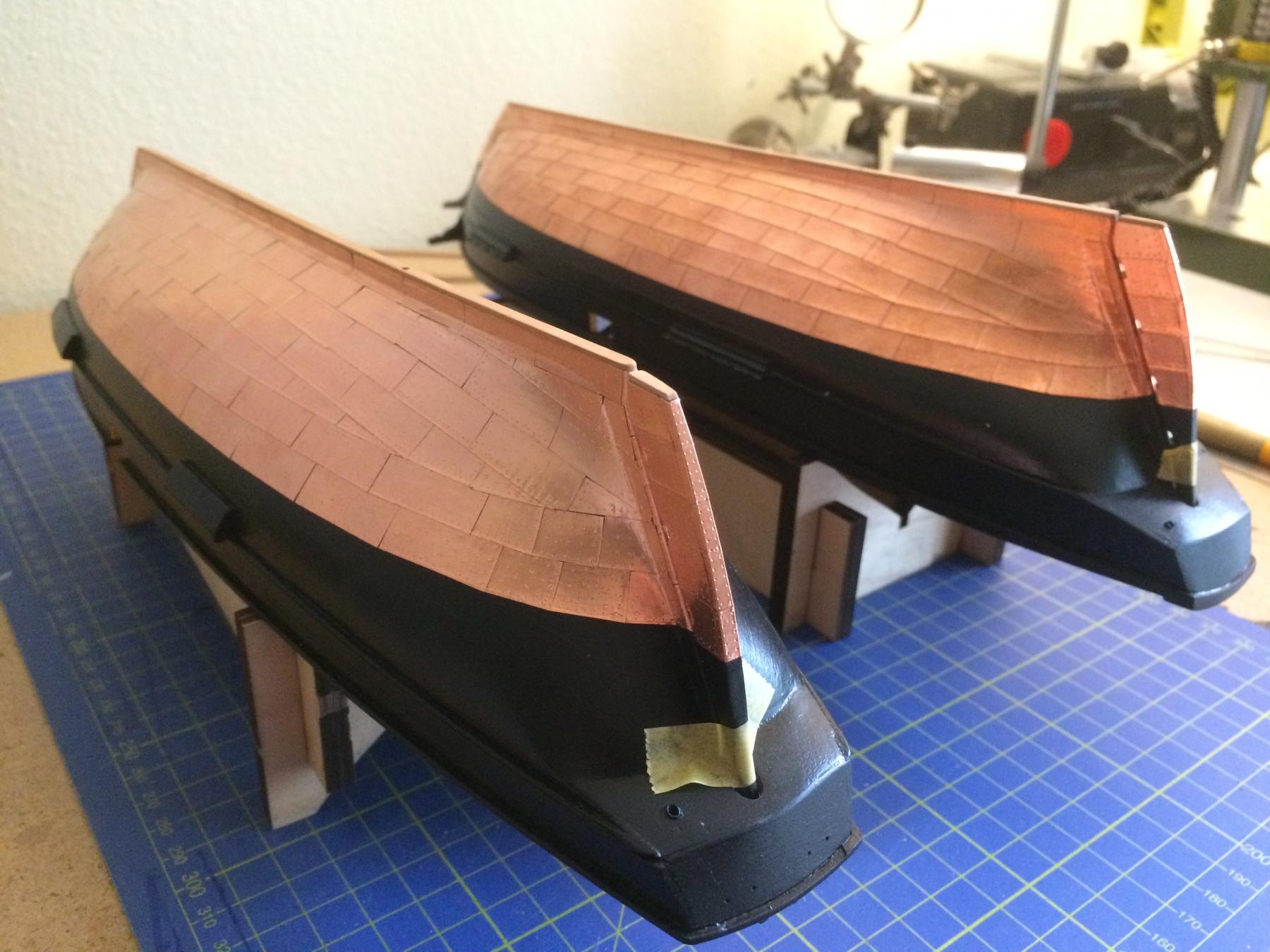
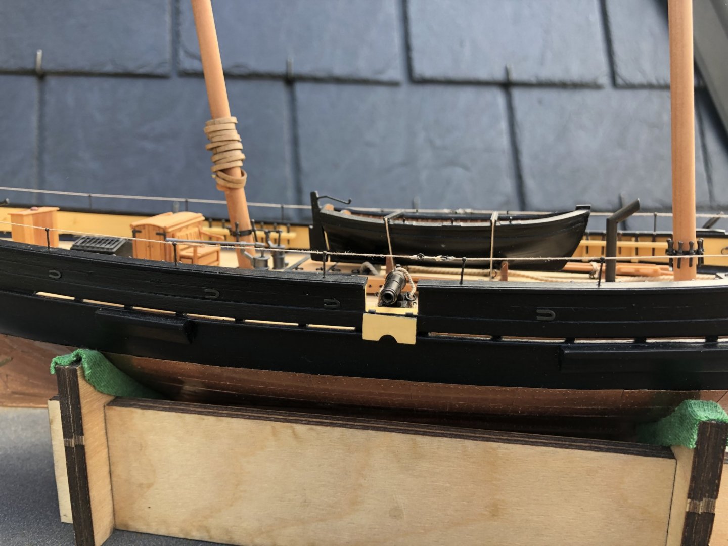
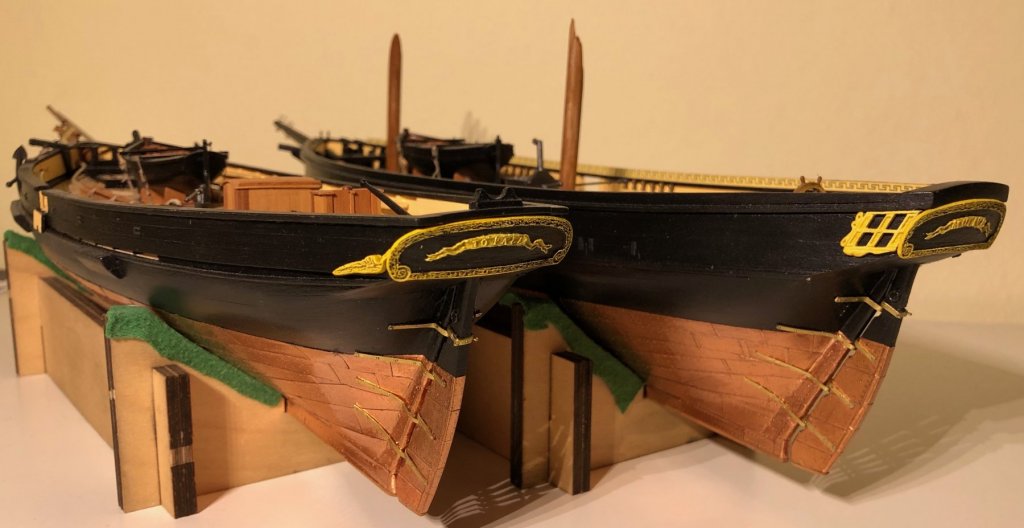
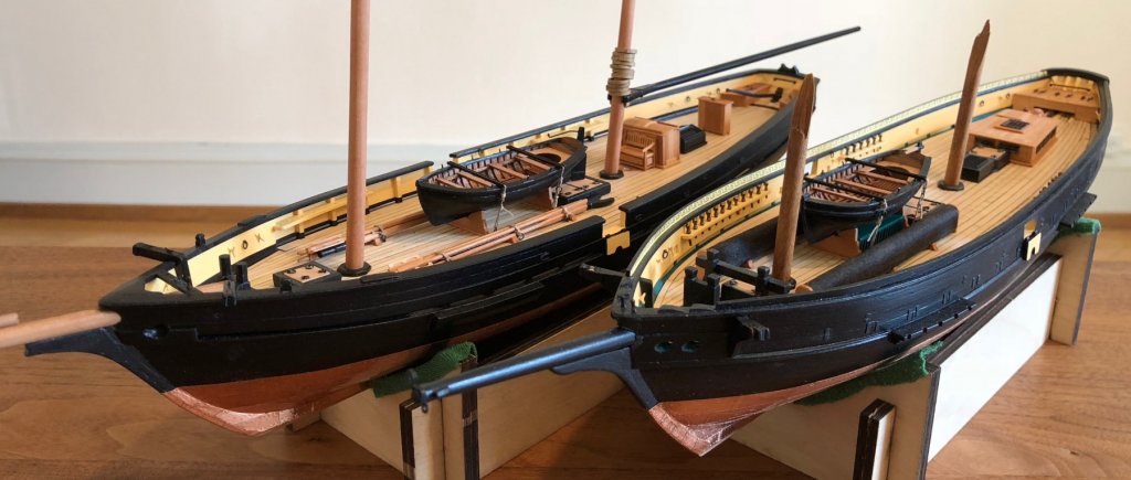
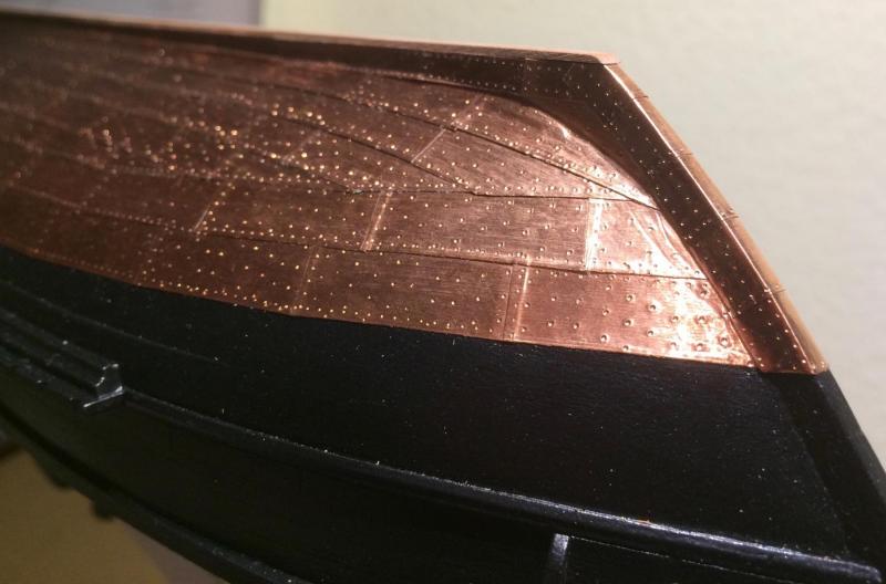
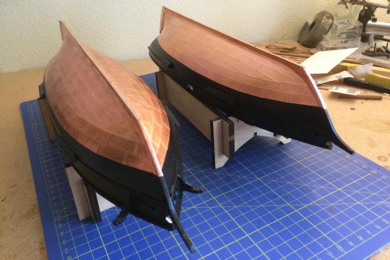
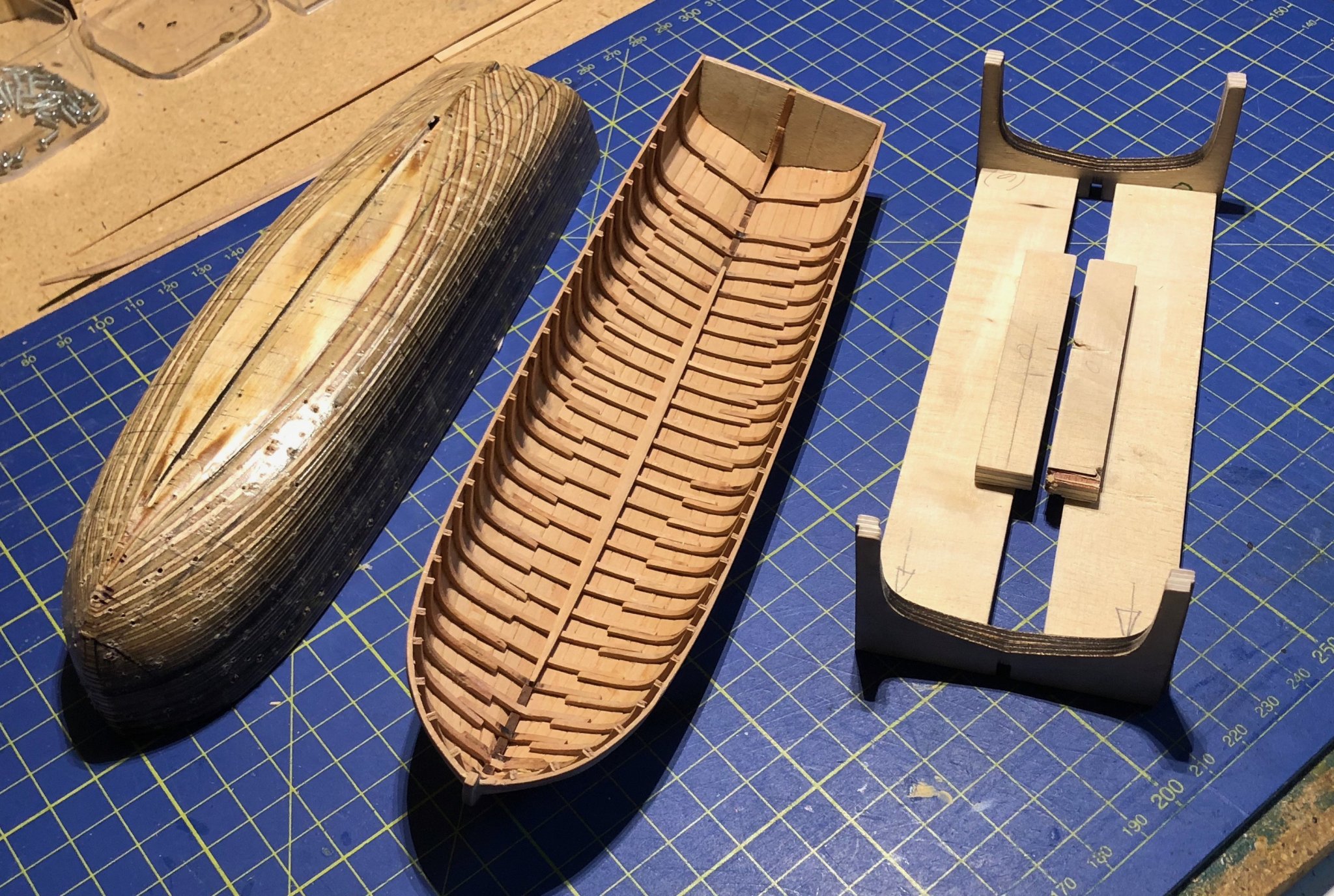
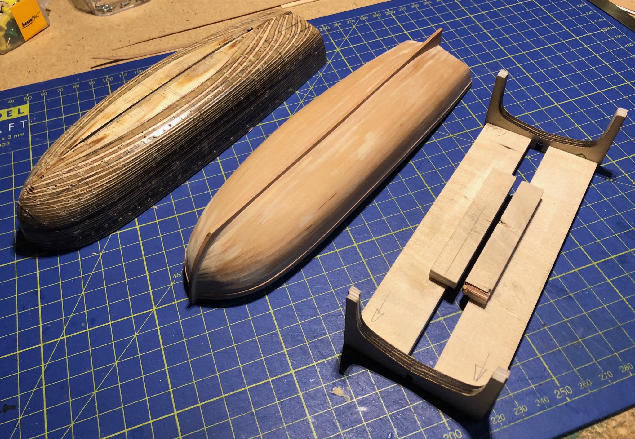
Thanks, Tony, you are kind. The important difference is that on Mutine's hull the tiles overlap (historically correct), but on the model this has a three-dimensional effect. On Topaze's hull, I put the tiles precisely along each other, so the copper skin is flatter and smoother.

- 121 replies
-
- 11
-
-
- la jacinthe
- schooner
- (and 2 more)
-
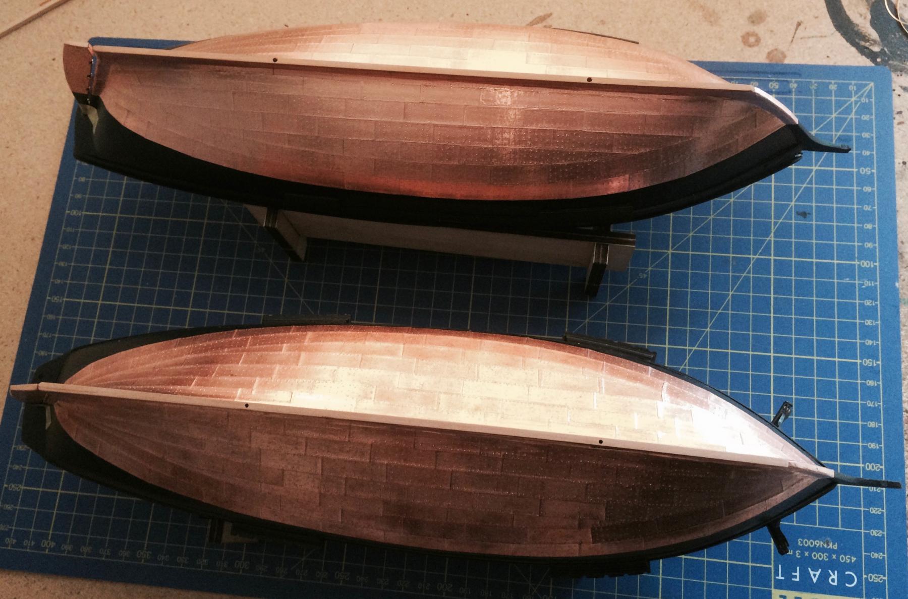
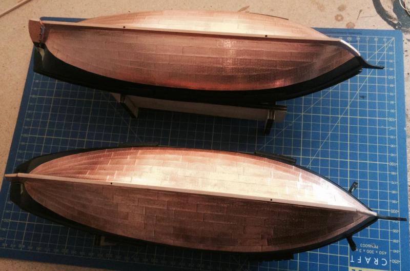
Finally, the coppering is done! One advantage of building two sister ships is that you can apply on the second hull what you have learnt on the first. You can see the difference between the Mutine and the Topaze, where I laid the tiles much more carefully. Sorry for the quality of my pictures - they were made with my old smartphone. Now the rudders have to be attached, an then I will be able to turn them around in an upright position again... Cheers, Gregor


- 121 replies
-
- 8
-
-
- la jacinthe
- schooner
- (and 2 more)


119.jpg.1019304ff6e9365a71c7b900c2daa484.jpg)