Gregor
-
Posts
225 -
Joined
-
Last visited
Content Type
Profiles
Forums
Gallery
Events
Everything posted by Gregor
-
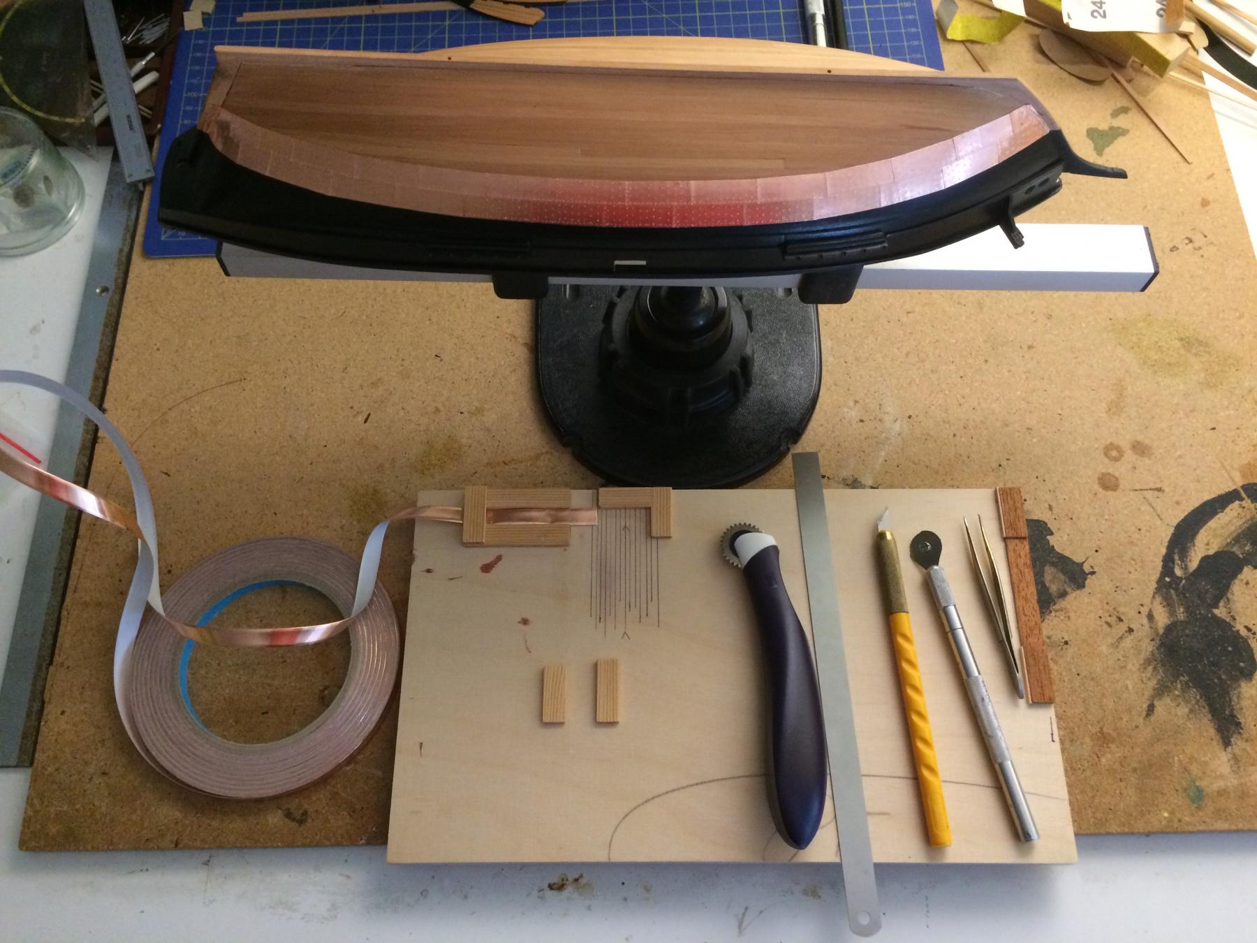
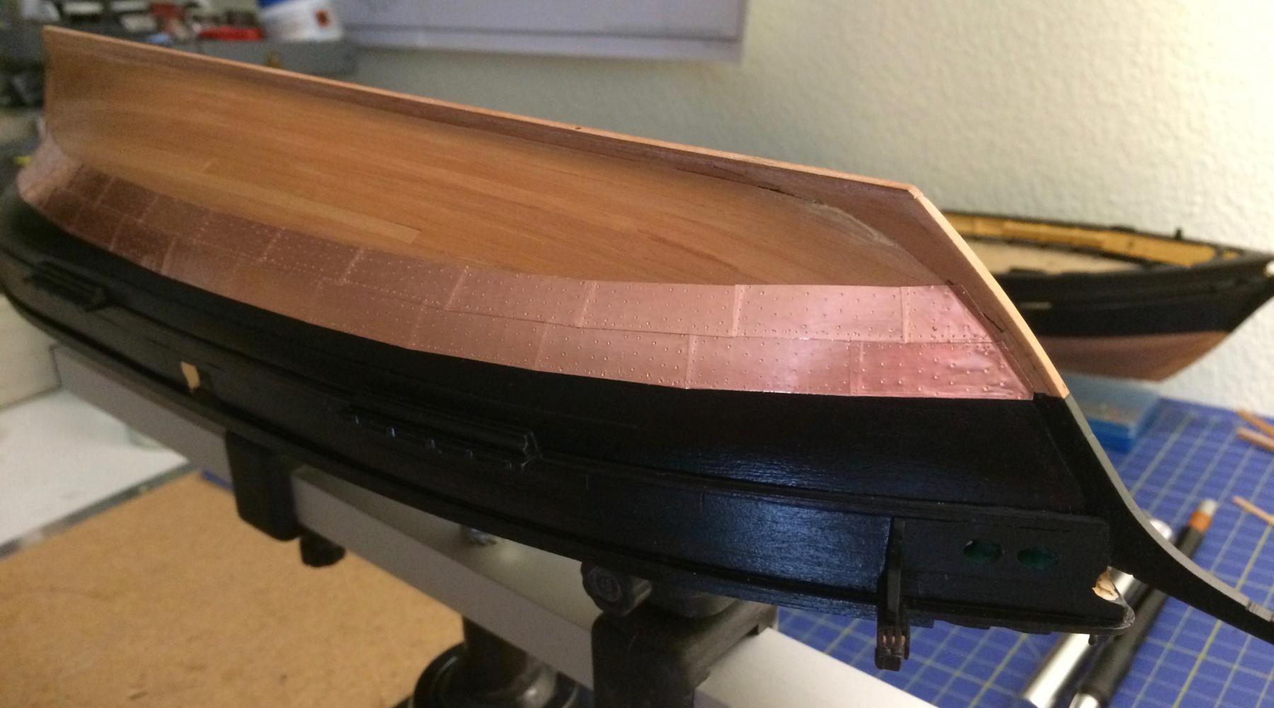
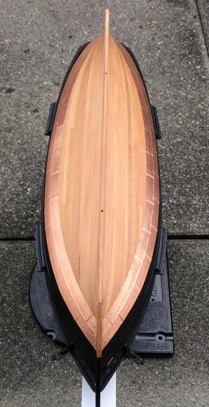
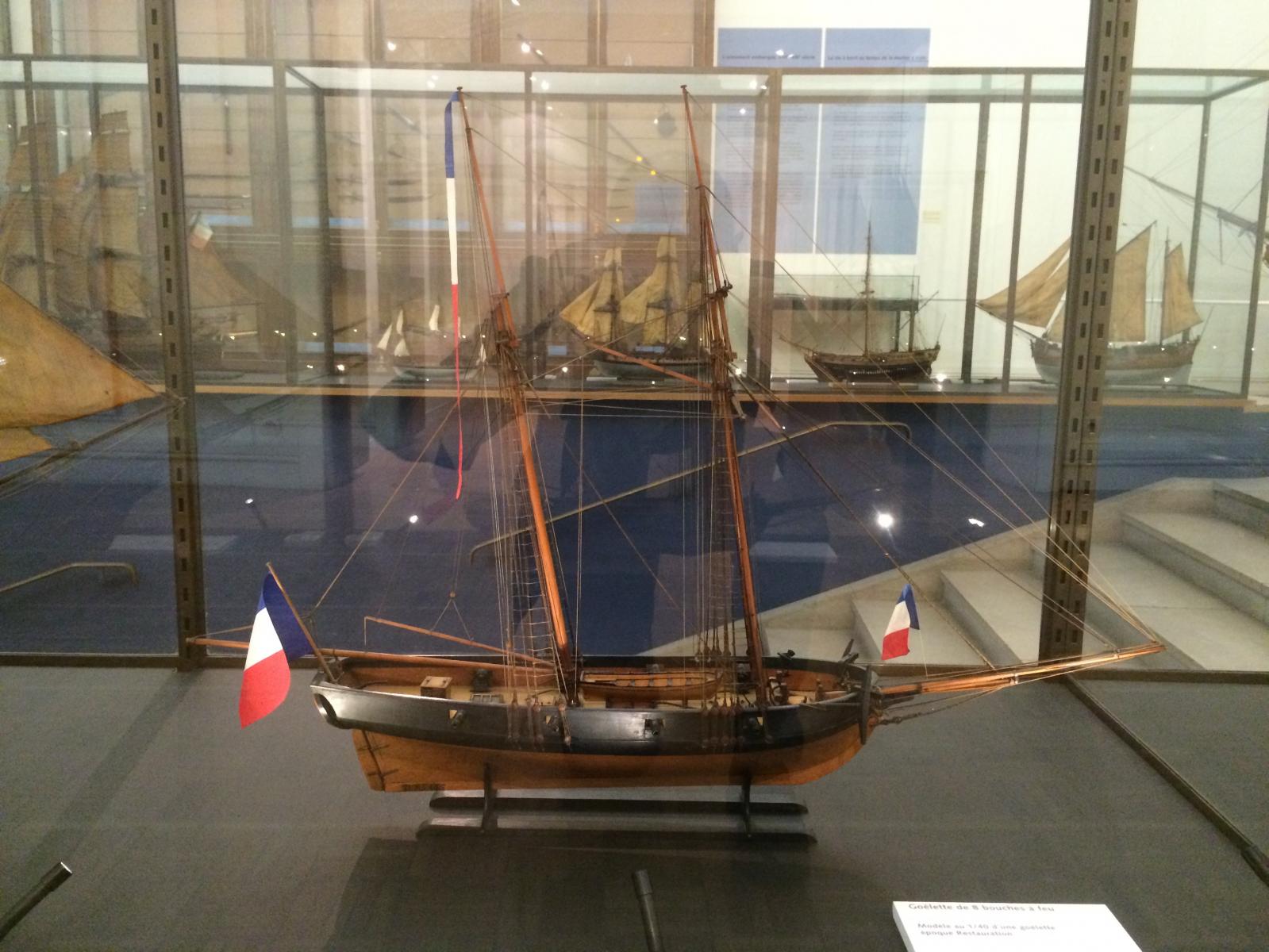
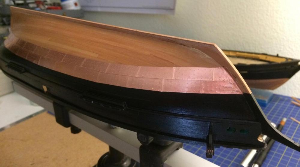
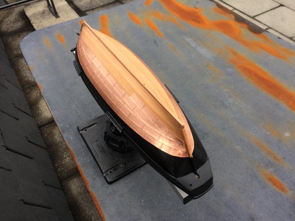
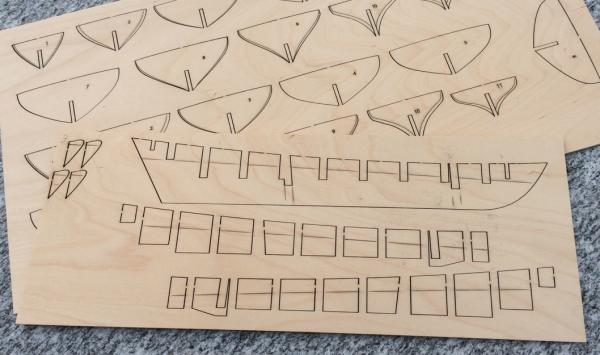
I've built some small stuff, and tried out different methods for coppering the hulls. When drawing the planking pattern of the decks, I decided to follow in both schooners the pattern of La Topaze (based on the contemporary model in Paris. The plan of La Mutine shows more, even narrower planks). As a historian I have to deny that the plan of La Mutine is "proof" of her actual appearance. Proof would require corroboration sources, such as a "devis d'armement", a document that describes dimensions and details and is part of the contract with the builder. I don't know whether the archives of Lorient dockyards survived WWII, but that's where such a document would be. But I think it can reasonably be assumed that her appearance as shown in the Atlas du Génie maritime, an official publication, could pass the scrutiny of critical eyes at the time. There are details open to interpretation or even missing, but in general it should be correct representation of a schooner of its type. For my project, thats enough. Here's what they are looking like at the moment: The pattern on the plank over Mutine's capping rail was laser printed after I found paper of the correct colour. As always, several attempts had to be made... The copper tiles are made from self-adhesive copper tape. In France, they were bigger than in England or Holland, and in 1:64 they are 25 x 8 mm. On a french ship, you start at the stern a bit above the waterline. Cheers, Gregor


- 121 replies
-
- 13
-

-
- la jacinthe
- schooner
- (and 2 more)
-
Congratulations and many thanks, Tony - I couldn't agree more with your conclusion. Every Sherbourne builder will make his very own version, learn a lot in the process and will be all the richer for all the valuable discussions with his fellows. As you were one of the motivators, back on MSW1, for me to pick up a Sherbourne kit, I very much enjoyed following your log here, and the discussions we had. I always admired your drive to learn every aspect of model making, and do everything by yourself. And not only that: By explaining how you achieved your results (and not hiding your errors) you have shown that a beginner can build a very beautiful model that will get a place of honour in his home. I wish you much pleasure with your next project. All the best, Gregor
- 269 replies
-
- 1
-
-
- Caldercraft
- First build
- (and 3 more)
-
Well, progress has slowed down a bit. But you are correct; originally I wanted to build a Jacinthe as shown by Jean Boudriot, in natural wood finish. Sadly I came to realise that my woodworking skills are not up to the task. And despite having given the impression that building two sister ships is easy, there are moments of doubts. My skill level was one reason for changing the plan. The other was my "discovery" of La Topaze by Bruno Orsel, a French modeller. His build log showed a thoroughly well researched model, based on experience and archival sources of the kind that doesn't exist any longer for the Jacinthe (they were destroyed in the last war). I was impressed; the switch was tempting and easy at that stage. We don't know how the Jacinthe really looked like in real life or even what kind of rigging she had (Boudriot based his reconstruction on the small picture of the Mutine, as he wrote himself). But we can safely assume it would have been in the region of La Topaze or its contemporary La Recouvrance, to make it seaworthy. What I learned while participating in a French forum was how the French naval authorities really sent out a standard plan to several dockyards, each to build two schooners. But the authorities kept a tight control over the basic design (see more here: http://modelisme-naval-bois.lebonforum.com/t3821-deux-goelettes-du-type-jacinthe-la-mutine-et-la-topaze-env-1830). As long as the dockyards respected the design, they could add individual details according to local customs or special needs. If you compare the contemporary model of La Topaze in Bruno Orsel's build log (in the same forum) with Jean Boudriot’s Jacinthe, you can discover several discrepancies: the position of the pumps, or the fore hatch (which had to be before the mast according to the ministry's specification). Things like these made the switch to Topaze very easy. But I would describe my "research" more as "corresponding with an expert". First result: Ripping out and replacing the pin rails in the Topaze; it's looking ugly at the moment… Gregor
- 121 replies
-
- 4
-
-
- la jacinthe
- schooner
- (and 2 more)
-
Tony – as always, your work is not only thoroughly researched, but also masterly executed and explained! And please don’t ever say again “it’s only rough compared… “. The magnifying lens is always a bit unfair. But what it shows us here is a cutter where you really could stand on the deck, pull on ropes and sail away – the stuff for dreams. Honestly, I admire you for all you have done with this originally simple kit. Your Sherbourne has left her cardboard home port behind for good, having sailed over the kit’s horizon long ago. Thanks for letting us follow! Gregor
- 269 replies
-
- 1
-
-
- Caldercraft
- First build
- (and 3 more)
-
Many thanks for all the support! I often doubt my decision to build the two schooners simultaneously. But you can view it from different sides: On the one hand, it's the price I have to pay for not being able to decide which one to build. It takes a little more time? It's my hobby. On the other hand, they are so small I really don't have to decide; I even have more choices. There are so many differences in the details to enjoy (I childishly wanted a steering wheel this time); and almost no mass production. Compared to a medium sized frigate, there is still less deck space to plank, and less hull surface to copper. Once you figure out how to build an element like a bulkhead pattern, you can use it on both hulls. And as only La Topaze will be fully rigged, I have only two masts to do instead of the frigate's three. Of course, it's an additional effort; I'm often confused between the two. But if I hit a wall I can put one aside and favour the other for a while. It might be a bit crazy to do a fist time scratch build that way, but I learn a lot for an eventual future project (HMS Beagle is the dream of the moment). Even with all the flaws and errors I've made so far, I quite like them sitting on the desk as a pair, patiently waiting. Cheers, Gregor
- 121 replies
-
- 3
-
-
- la jacinthe
- schooner
- (and 2 more)
-
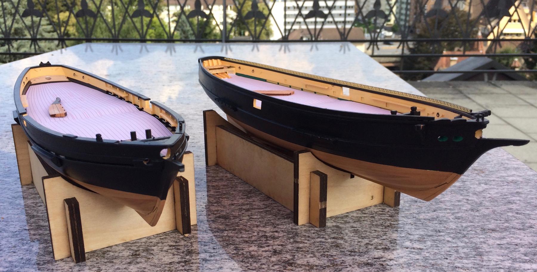
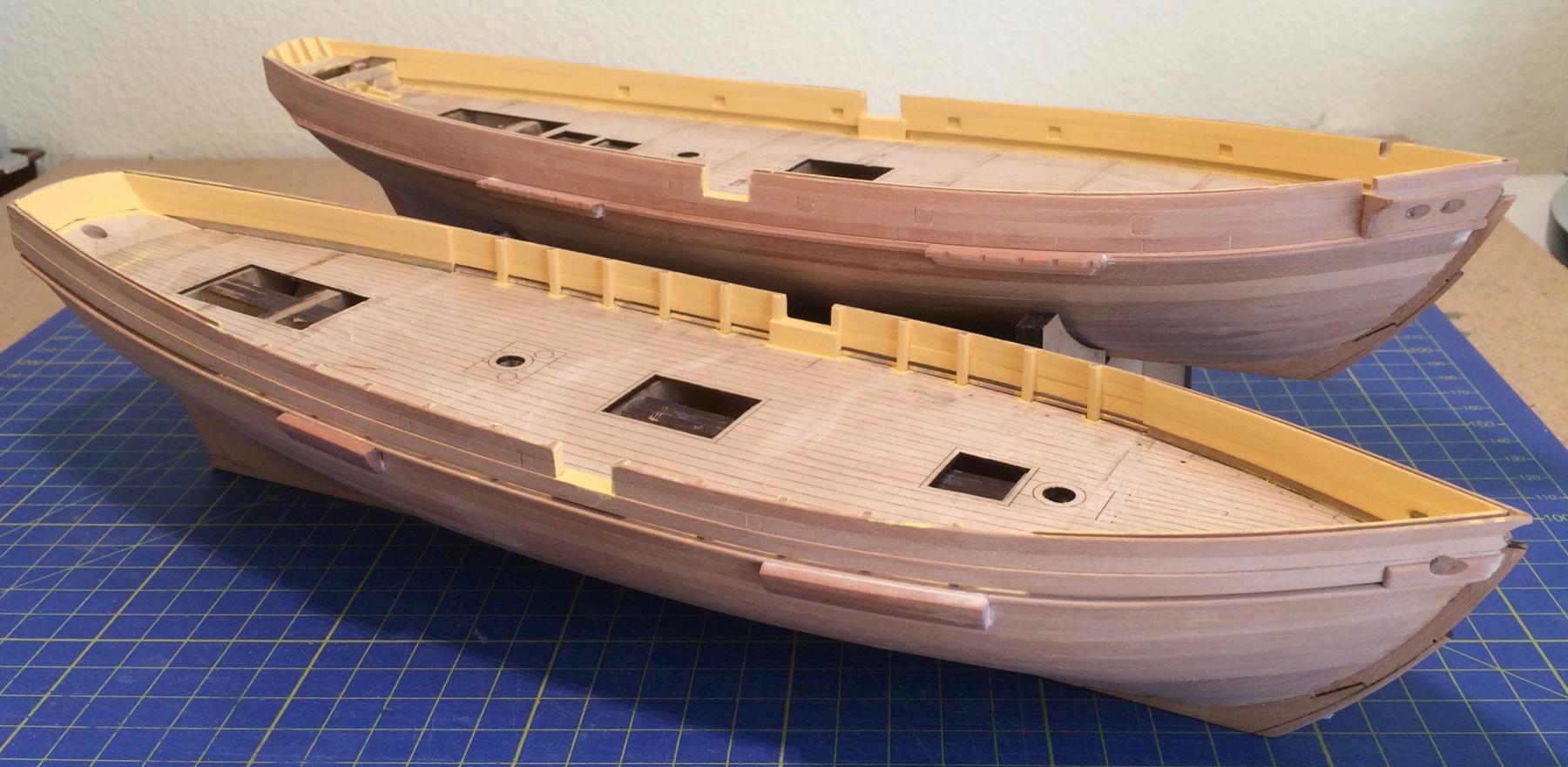
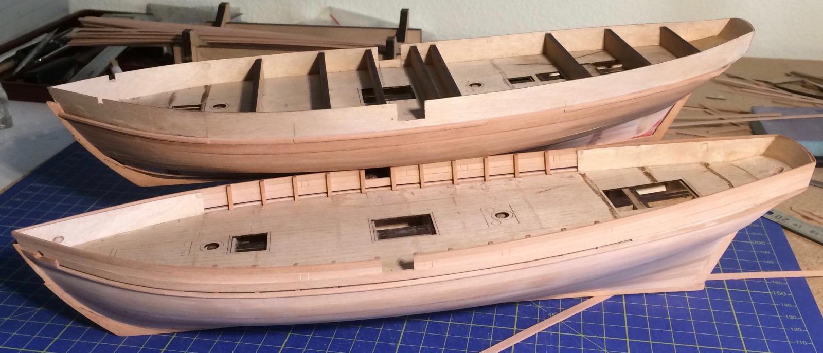
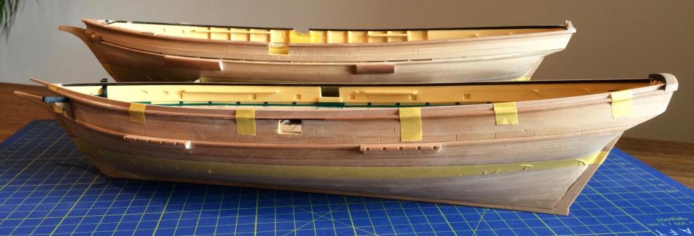
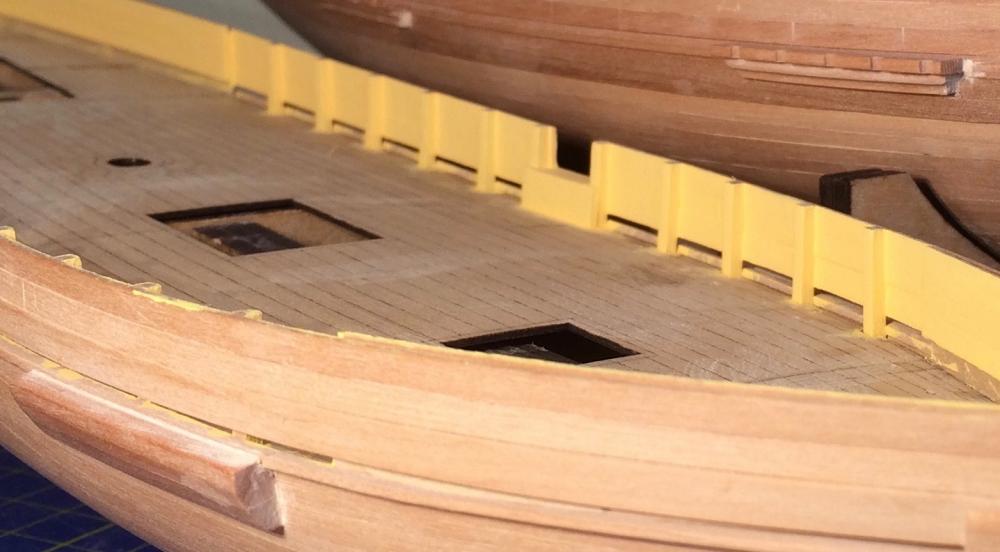
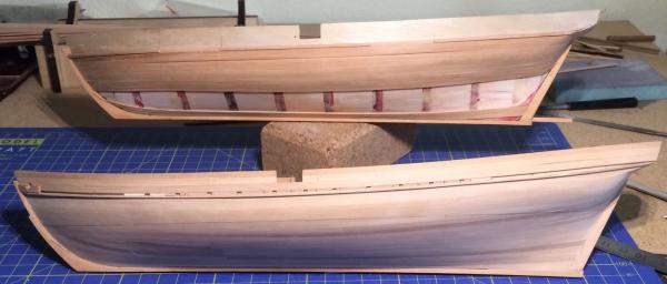
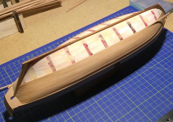
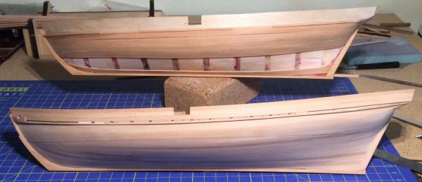
It's a rainy weekend, and I'm still working on the railing caps. As you can see, the two sisters are slowly growing apart. Enjoy, Gregor

- 121 replies
-
- 13
-
-
- la jacinthe
- schooner
- (and 2 more)
-
Oh, Juraj, my mistake: "36. Bassins de plomb pour l'équpage" translates correctly into "basins for the crew". So we have to find a solution for the plumbing. There will be a hole somewhere between the deck and the basin... Gregor

- 121 replies
-
- 4
-
-
- la jacinthe
- schooner
- (and 2 more)
-
Excellent (and huge) work! I will follow you very closely here. How I love these schooners! All the best, Gregor
-
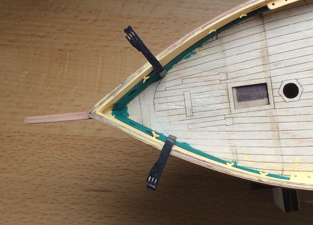
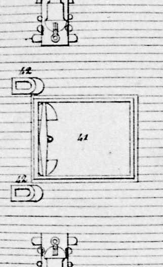
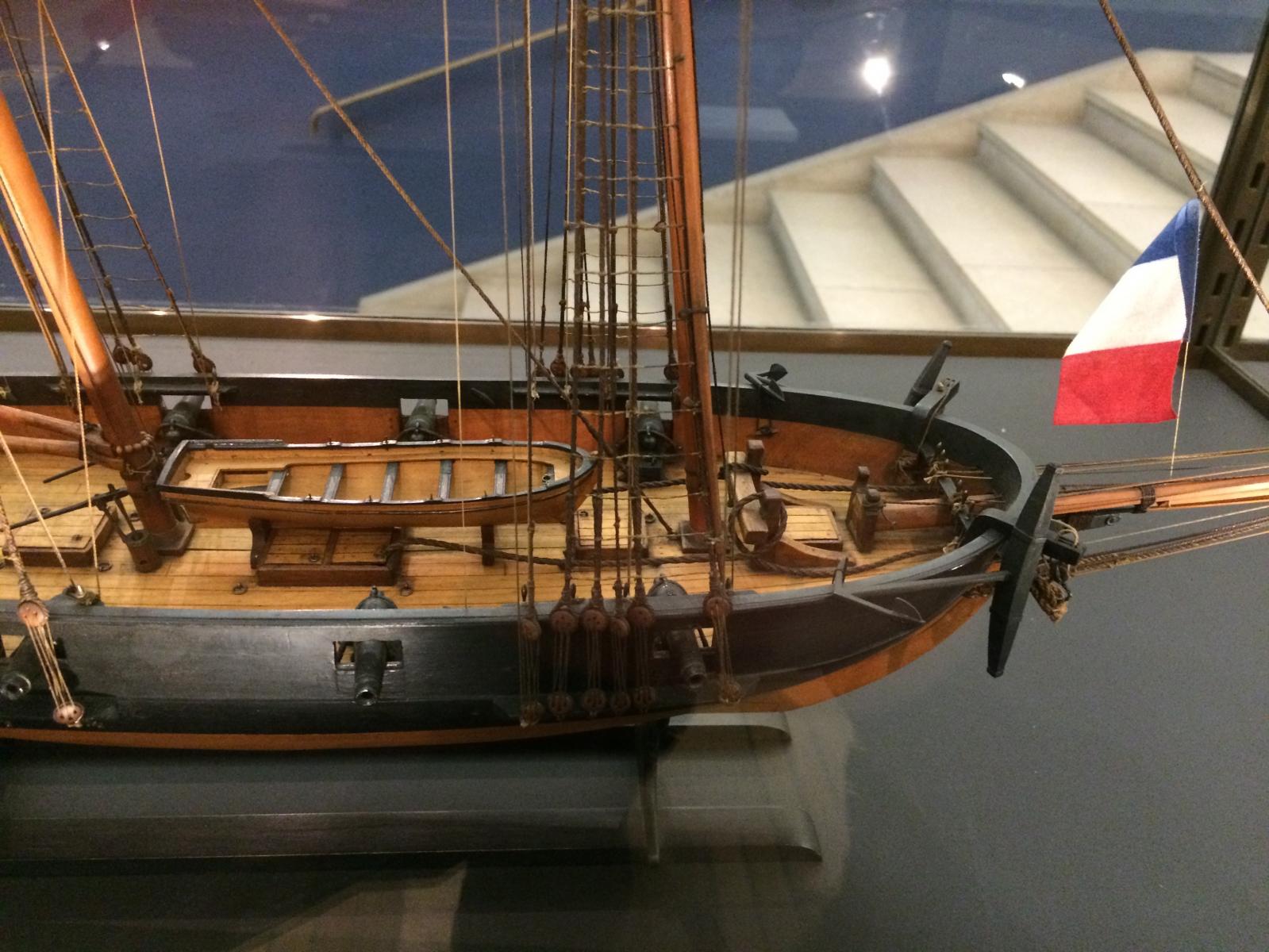
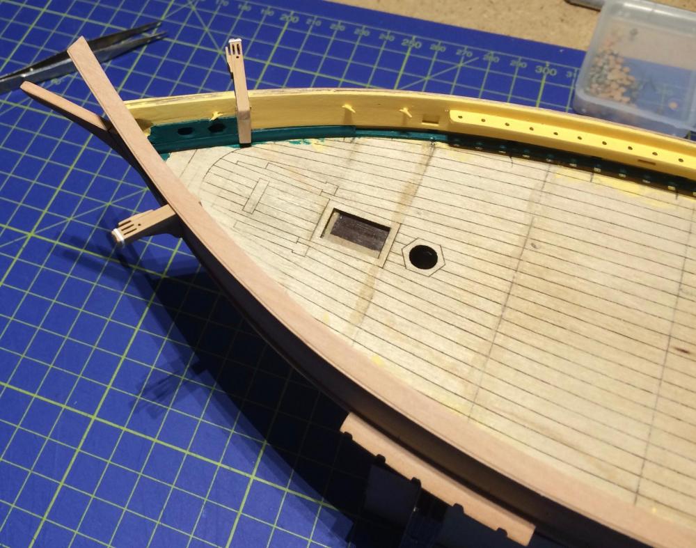
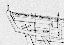
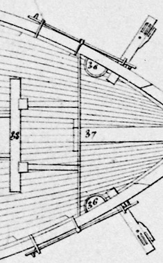
Hi Juraj 1. I don't think there were seats of ease for the ratings. They had to relieve themselves over board; probably from the fore chains (there are reasons why these ships had smelly bilges). As was explained to me in a French forum, some French ships even had holes in the chains for that purpose. Alas, these schooners had nothing of the sort. The small lead basins (no. 36 in the plan) are there to store small equipment. 2. The basic open layout of the Jacinthe type schooners guarantees for a wet experience. Also, the bulwarks are relatively low, affording not much protection. That's why the Topaze has an additional line over the (almost closed up) bulwark. The Mutine's bulwark was built even sturdier and a little higher, with an additional plank set on the capping rail. On the inside, it was decorated in neoclassical style with an elaborate Greek pattern very much in fashion at the time. Most contemporary models of French ships show a simpler decoration with diamonds (rhomb) on the inside of the bulwarks. You can find this diamond pattern decoration also on La Recouvrance. The capping rails and the additional plank have to wait till I have finished the catheads: Gregor

- 121 replies
-
- 6
-
-
- la jacinthe
- schooner
- (and 2 more)
-
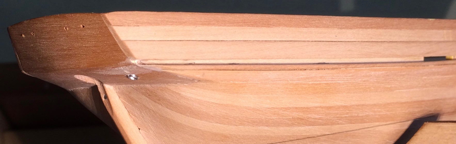
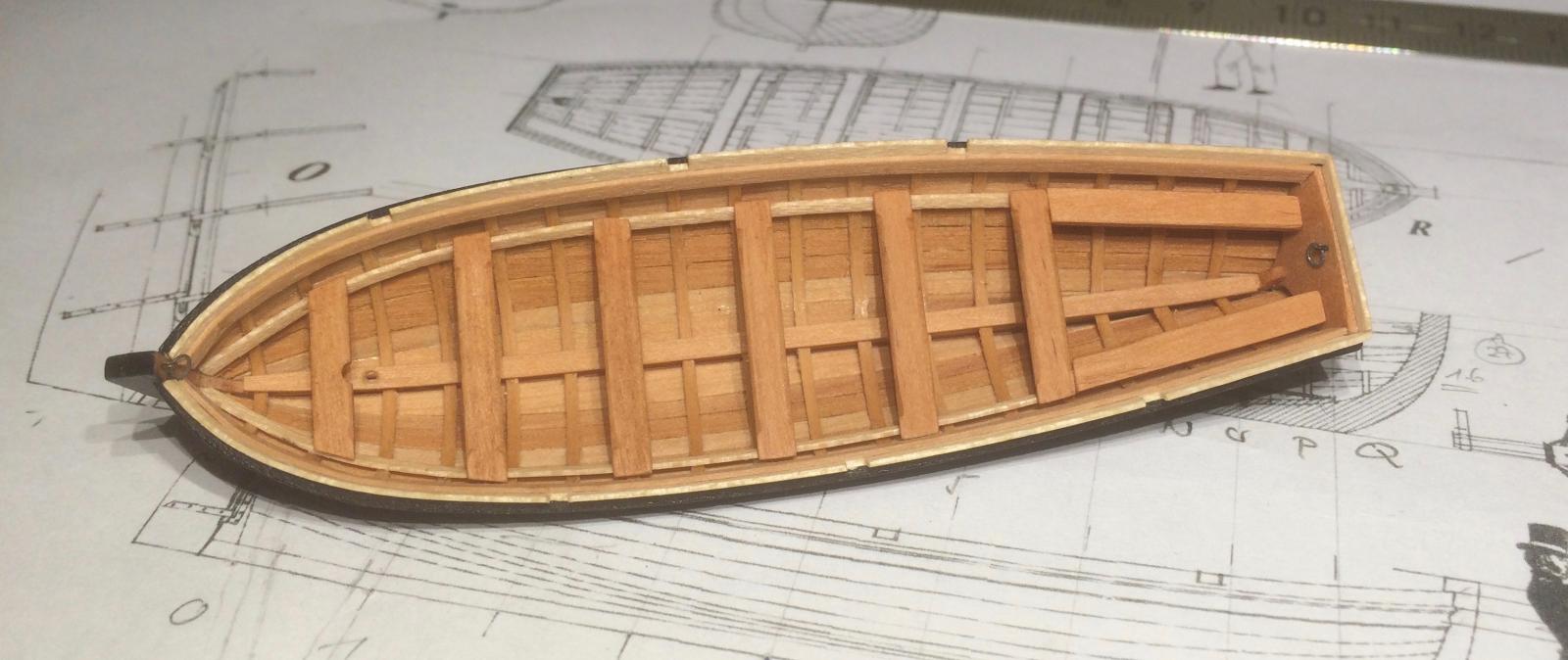
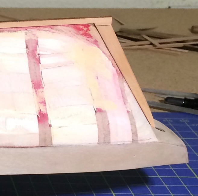
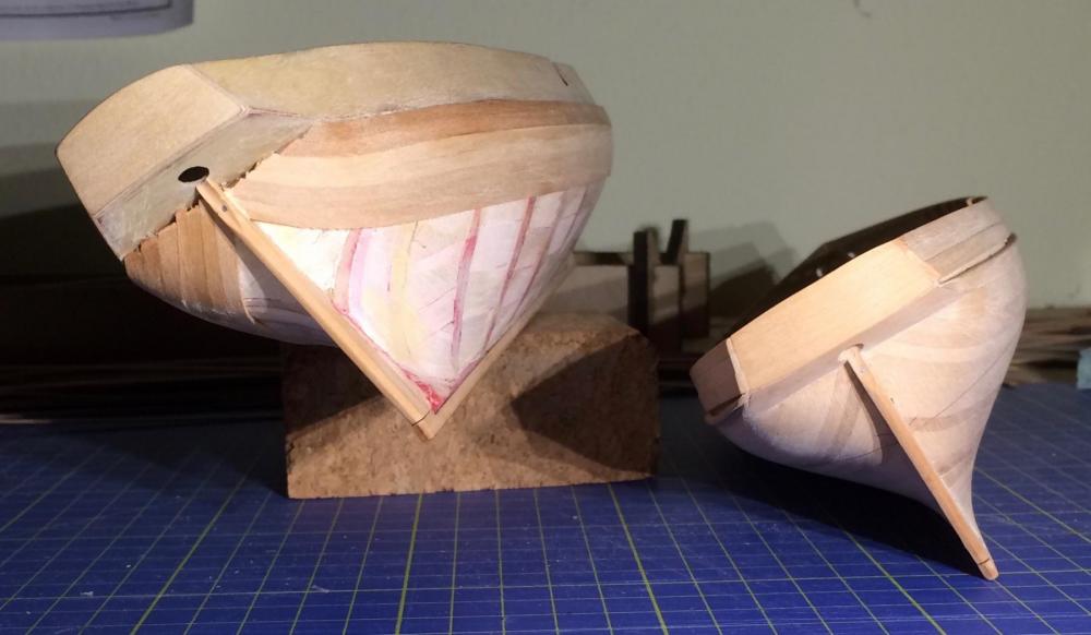
Oh, how I envy you - I try to imagine the feeling of standing on a schooner's gently moving deck...! At least, I possess a book about the first voyages of La Recouvrance (Carnets de bord), which I'm reading slowly, with the help of a dictionary. For the transom, as described I used the simplified method I learned with the Sherbourne kit (cutters and schooners are close relatives, after all). Maybe these images help? Enjoy. Gregor

- 121 replies
-
- 6
-
-
- la jacinthe
- schooner
- (and 2 more)
-
The hull on deck measured 21 m, fully rigged from boom to boom the schooner totals about 37.5 m.
- 121 replies
-
- 1
-
-
- la jacinthe
- schooner
- (and 2 more)
-
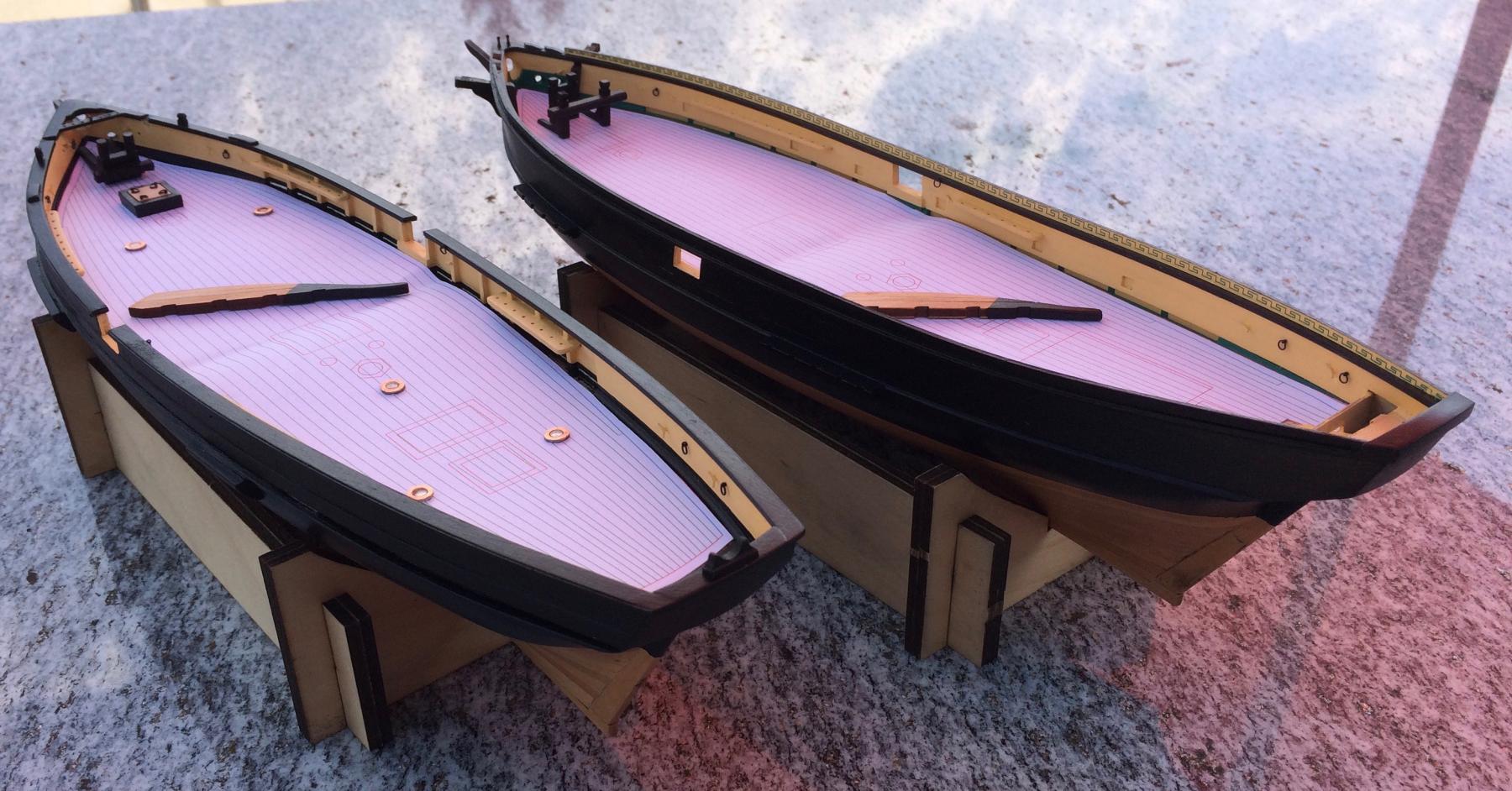
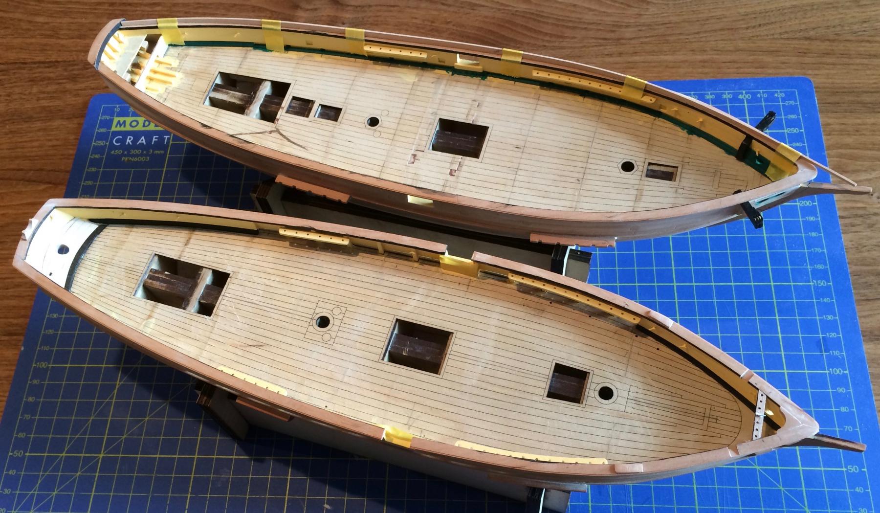
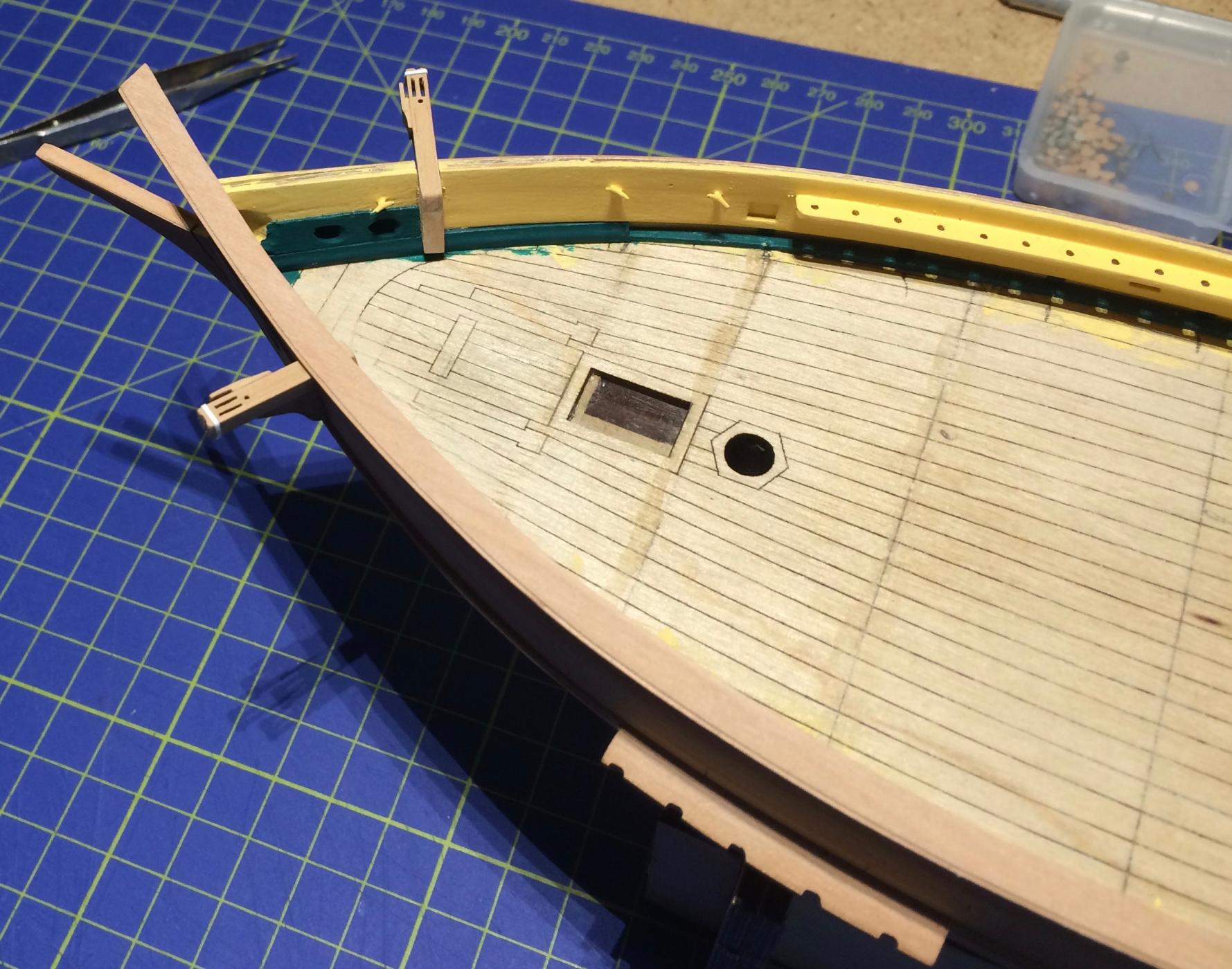
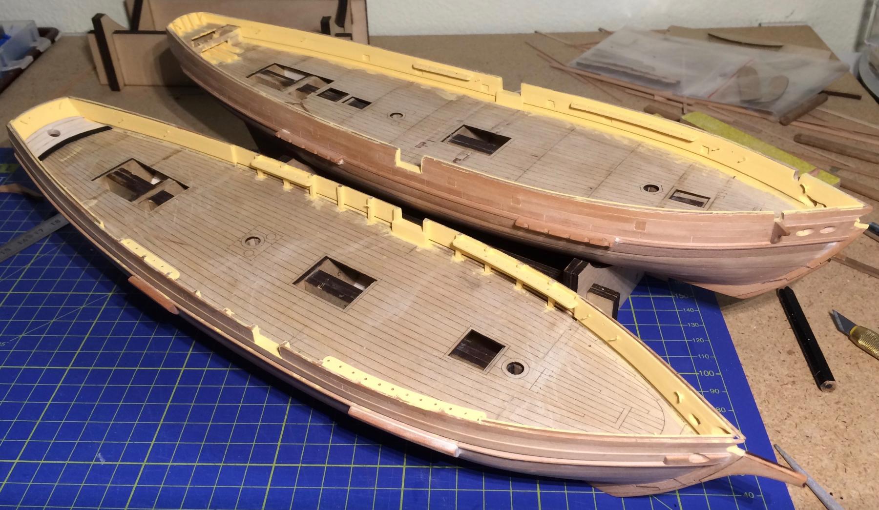
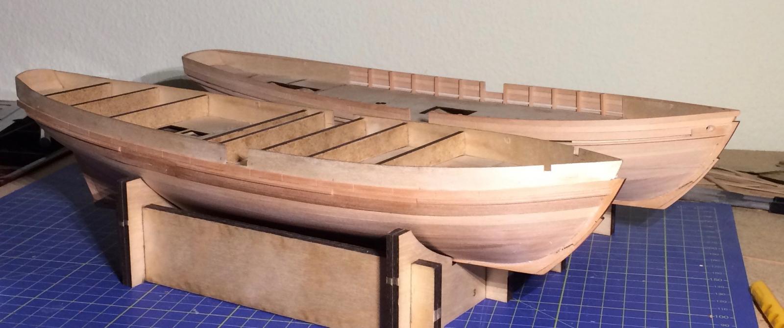
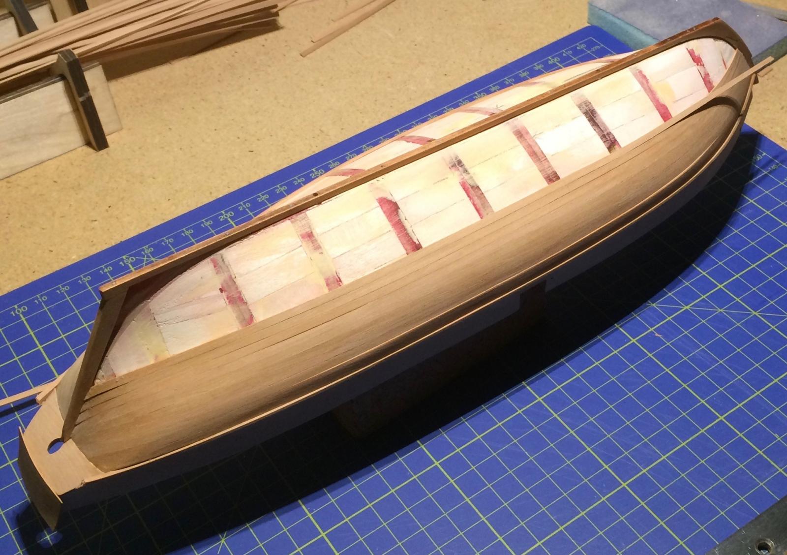
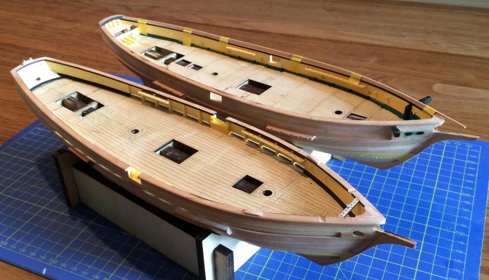
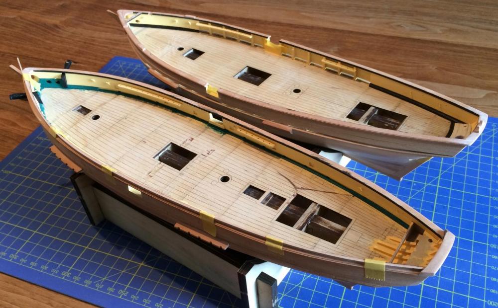
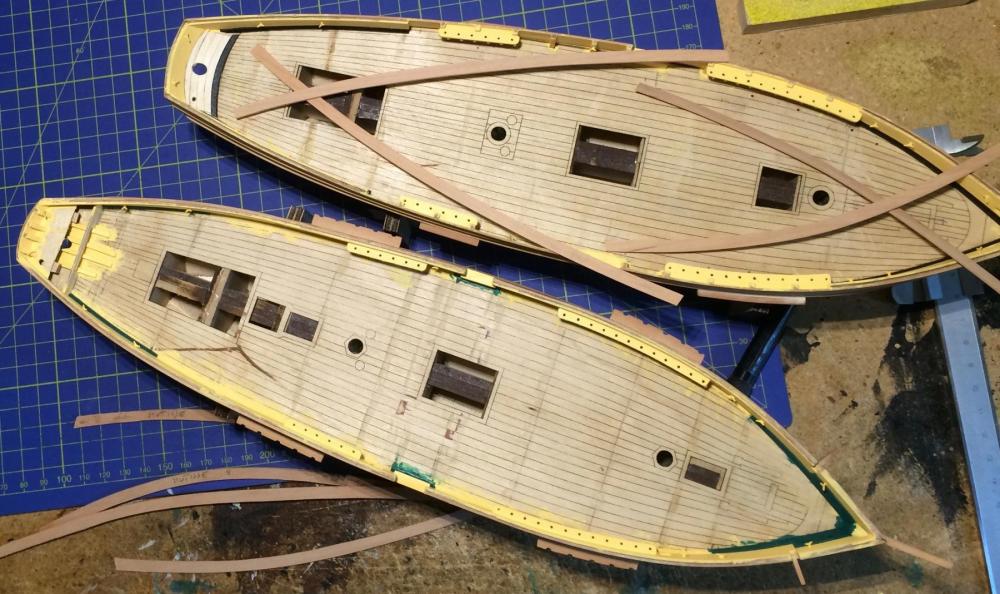
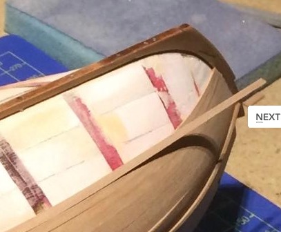
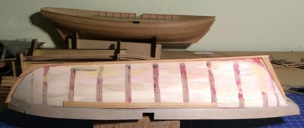
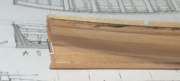
Slowly, my hulls are looking like real schooners. First colours were applied; straw yellow on the bulkheads, green (La Mutine) and black (La Topaze) on the waterways. The first maple planks appear on La Topaze’s deck; there will be chests on either side. The plywood in La Mutine will help me build a chest there; it still grants access to the rudder hole for the moment. The channels gave me some headaches. French schooners of that time are showing all kinds of highly individual, often massive solutions. On the two contemporary models shown earlier in this log, from the Musée de la Marine in Paris, they look like these: First Empire: Restauration period (like the Jacinthe-class schooners): An excellent example of channels of this kind can be seen on the modern reconstruction of La Recouvrance, a French schooner of the same time (http://modelisme-naval-bois.lebonforum.c...ght=recouvrance): No. 1 (top row, fourth image from the left): http://www.atraverslobjectif.com/photos/la-recouvrance.html#prettyPhoto No. 2: http://www.pbase.com/image/44215117 Here is how it looks on my schooners. In La Topeze (in front) the channels were built from two massive pieces of timber, according to Boudriot. In La Mutine, as in La Recouvrance) the channels are supported by a piece of wood (see the detail from the Atlas du Génie Maritime: http://modelshipworld.com/index.php/topic/9743-french-schooners-la-jacinthe-type-la-mutine-and-la-topaze-by-gregor-–-164-scale-1823-1835/?p=384551). Now the decks are in planning, railing caps are being prepared, and a very important piece of equipment has been installed (at least for the two officers on board). Cheers, Gregor


- 121 replies
-
- 8
-
-
- la jacinthe
- schooner
- (and 2 more)
-
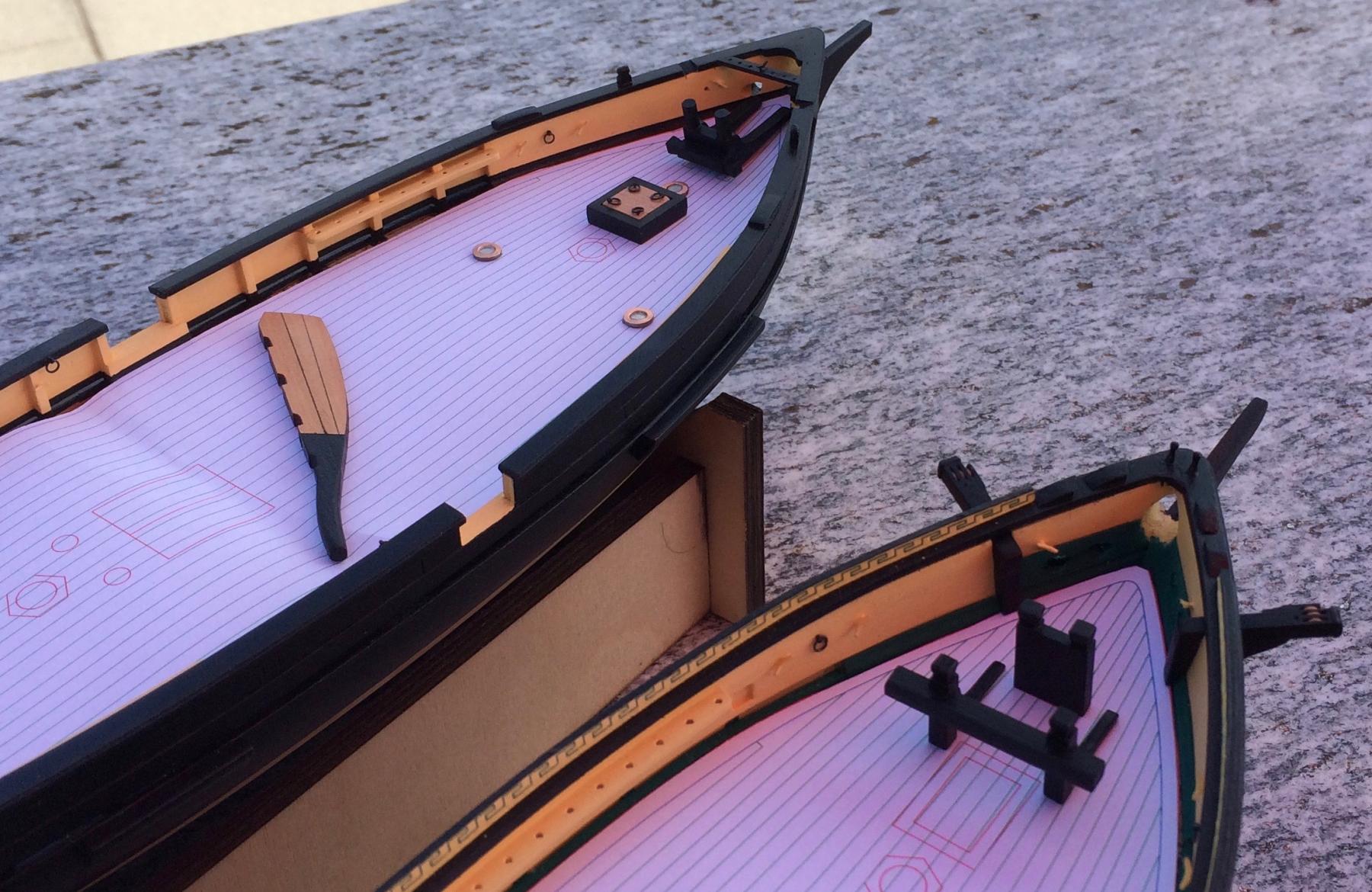
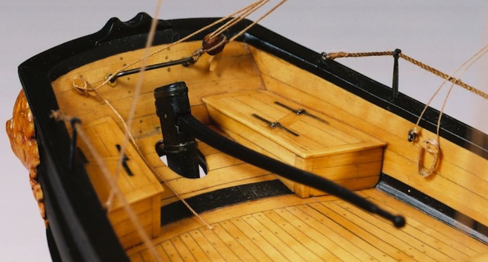
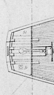
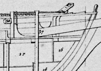
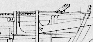
Jurai, I'm not convinced. In the stern, the thing you call a step is a locker or cabin-like structure, like a high bench. On the starboard side it covers the seat-of-ease for the officers (51). It is described as "Caissons couvrant les bouteilles…". I don’t know what is meant by "bottles", but you can clearly see what it is: Flags were stored on the port side; the middle part covers an iron tiller. Please refer to the build log of Bruno Orsel (http://denis-59.forumpro.fr/t792-la-topaze-goelette-de-1823): On La Topaze the arrangement is very similar, although the middle part is left uncovered. It has nothing to do with the deck itself. I still don't see a step at the bow. I can't identify every detail yet, neither my "iron bar" nor your "beam"; but seen from the side there is clearly a flush deck. If invited to speculate I would be tempted to call this "beam" a piece of wood, there to protect other parts from the anchor chain. To speculate further, it could be a "chain-guide", as shown in the Atlas du Génie maritime (for a much younger and bigger corvette). I think we have to accept that the Atlas is not a collection for modellers like us, but a publication where a proud nation shows its might and ingenuity in a contest with other industrialized countries. There is another point: If there is a step, there should be a reason for it. Underneath there are storerooms, according to the plan. But there is not much room to gain with an expensive modification of the basic design. And finally, although it's always sound practice to doubt authorities, I think Jean Boudriot would have discussed a modification like that in his work. Let's build our very own interpretations – I will stick with the flush deck "iron bar" for the moment. Gregor
- 121 replies
-
- 6
-
-
- la jacinthe
- schooner
- (and 2 more)
-
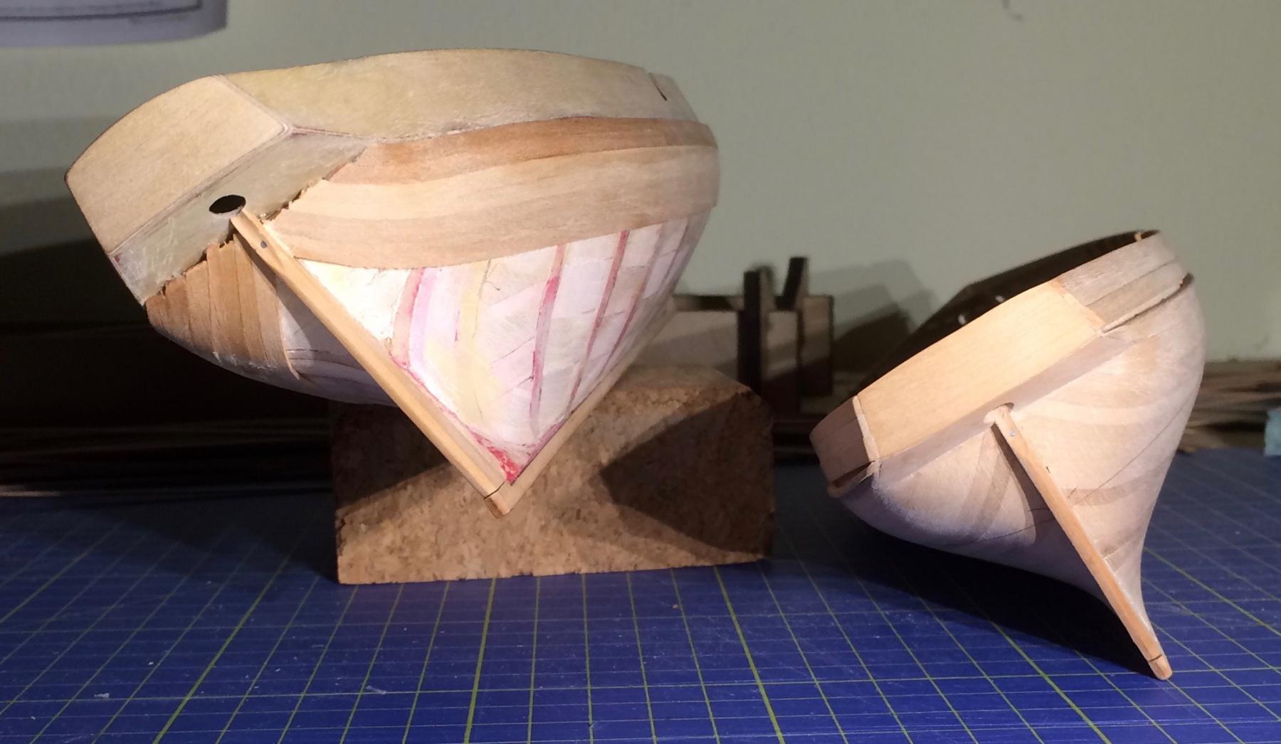
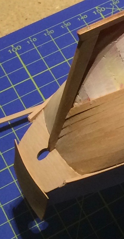
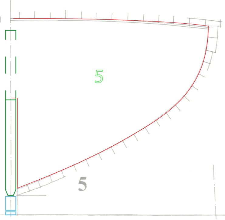
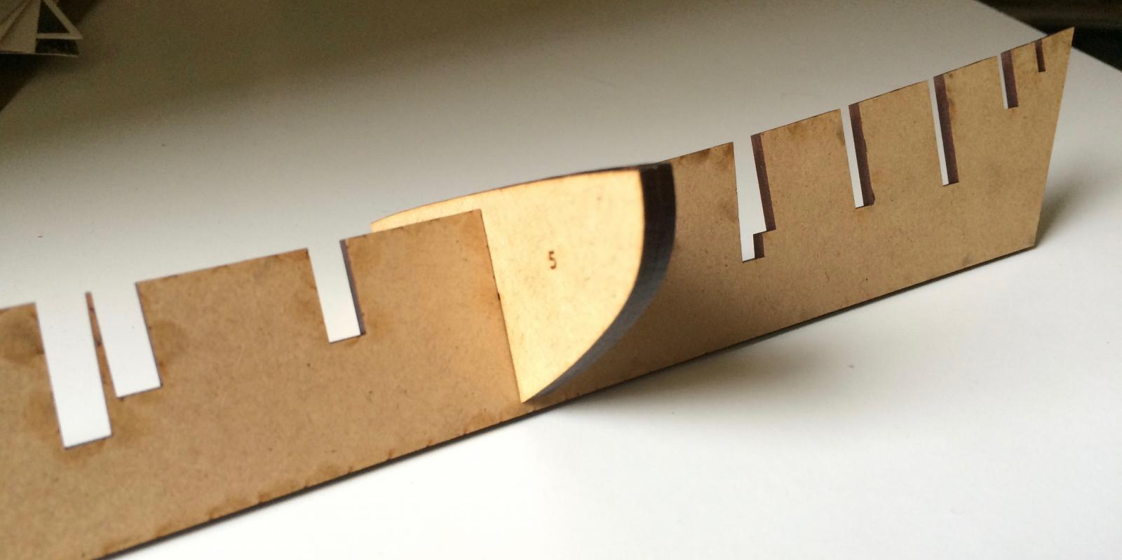
Toni, don't hit yourself - it might be my english... Do these pictures help? The space between the bulkheads (red) was filled with small pieces of ply. There is only one layer of 1 mm planks. A rabbet was cit in the fore-aft bulkhead (green), then the keel (blue) was added. As you can see here, the planks didn't fit in the slot: As both hulls will be coppered, let's call my garboards "simplified". I just let a 1x3 mm plank run naturally, with a filler, as shown in Boudriot's plan. Of course it reminds us of the Sherbourne kit (what else?) Bit this might help you also: http://www.segelschiffsmodellbau.com/t3269f795-Die-Bauanleitung-pur-Bemerkungen-und-Diskussionen-in-den-jeweiligen-Themenfaeden.html The precision of laser cut parts certainly came in handy. After drawing the bulkheads, it was very easy to draw also some filler parts; they helped to get a straight hull, together with an Amati stand I own. Still, a proper building board would have been useful - some force was necessary to get the keel straight. Bun once the space between the buklkheads is filles, you have a very solid hull, prepared to take a heavy sanding. I prefer this method to the one we used for the Sherbourne. Yours, Gregor
- 121 replies
-
- 7
-
-
- la jacinthe
- schooner
- (and 2 more)
-
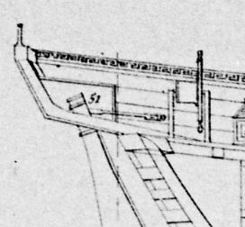
@Jurai: Here the promised explanation (flush deck of La Mutine). At the stern there is a counter, as described by Boudriot. At the bow I see an iron bar (probably part of the rigging instead of belaying pins?), there is no step at all. The iron parts over the rail are also used to attach the anchors with chains, as described in the Atlas du Génie Maritime. Detail no 36 are the famous lavatories or heads for the common sailors - no modesty protected there. It really is the same hull - if you discount the distortions of a old print, photographed almost two centuries later, you can see how both plans match each other (I traced the main lines in AdobeIllustrator to draw bulkheads and keel). Cheers, Gregor I made new screenshots to show detail no 38.
- 121 replies
-
- 5
-
-
- la jacinthe
- schooner
- (and 2 more)
-
Wow, aviaamator, beautyful! You two (or three, counting in capt'n Sparrow) should really open your own build log; I would be very happy to follow your progress and exchange views. Your Jacinthe deserves to be admired fully. Yours, Gregor @Jurai: I will give you an answer to the deck question asap.
- 121 replies
-
- 3
-
-
- la jacinthe
- schooner
- (and 2 more)
-
Hi Juraj It would be great so see another Jacinthe type schooner here! I try to answer as well as I can: 1. The plan of La Mutine from the Atlas du Génie maritime (the one in your book, the one I showed here at the beginning og the build log) is the only one I have. You can get a better copy from the historical service of the Musée de la Marine in Paris for a few Euros (and the promise not to publish it). There is no set, only this one sheet. There is, however, the plan that was sent to the Lorient dockyard in 1823/24. A copy of this plan can be had from the Service historique de l'armée in Vincennes (they insist the plan is from a younger date because of a dated annotation in the margin, but it's without doubt "our" Mutine). That's the plan you can do without, because it shows an identical construction to Boudriot's Jacinthe, and gives no more details. 2. The bulwarks of La Mutine are basically the Jacinthe's, with more planks. If you follow the links to Bruno Orsel's La Topaze, you see the same, only with additional stanchions. Depending on the scale you plan to build your model, you can do exactly that. I choose to work with a bulwark pattern for two reasons: It's my first scratch build, so I stick to what I know; and that is the Sherbourne kit from where I borrowed the idea. At 1:64 the bulwarks are about 3 mm thick – instead of working with 2 mm stanchions and 0.5 mm planks I preferred a solid bulwark (ply, 0.8 mm) and 1 mm planks. As you can see in my log, I used temporary bulkheads to place the ply. It was design by trial and error, first with paper, then with ply, and it took a while… The plan from the Atlas du Génie maritime is not precise enough to take measurements. But you can easily go to Boudriot's plan and "fill the gaps". At least, that's what I did; a lot of comparing. 3. Well, the aft lavatories are covered, to protect the modesty of the officers… A better copy of the plan helps a lot (then you will see: it's the same flush deck, no steps). I'm still working on the hulls, so for many of these details I have more questions than answers myself. But that's where the real fun is. The Atlas shows a wealth of information about lavatories and everything else the French navy built in the 1830's. So I'm looking forward to more research, discussions, and visits to French museums. If in doubt, start a Jacinthe project. La Topaze and La Mutine were working ships; Boudriot's Jacinthe is like Platon's (or M. Delamonière's) ideal of a schooner. 4. Bruno Orsel's Topaze shows (based on thorough research) anchors stowed inboards, lashed on deck. Lowering a heavy anchor below deck, near the centerline, might influence the balance of a ship favourably… But here I don't have answers yet. As I feel they are not yet important to the construction (like the questions about windlasses or capstans), they can wait. But there is a paragraph about anchors in Boudriot's book, somewhere. I feel quite confident it's possible to build a Mutine, without having all the answers beforehand. Just do it. Yours, Gregor
- 121 replies
-
- 5
-
-
- la jacinthe
- schooner
- (and 2 more)
-
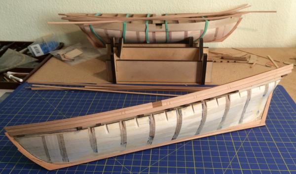
I don’t mind explaining the method I used here at all: Boudriots plan is in 1:48 scale, my models in 1:64. That means my keels and fore-aft bulkheads are only 3 mm thick. Working with veneer would mean a fore-aft bulkhead of only 2 mm, very prone to warp. As both hulls will now be painted black and coppered, there is really no need for veneer to hide the plywood (Boudriots model has a natural wood finish). When I chose this method, my only experience was with the Sherbourne kit we both know so well. And I wanted to build a painted and an unpainted hull, originally. As you can see in this picture (MDF parts for testing; I used birch ply for the models) I added 1 mm to the fore-aft bulkhead, and then made a rabbet by chamfering it before filling the space between the cross-bulkheads and adding the keel parts (pear). Main lesson learned: The rabbet I cut was too small; it would have worked with planks of 0.5 mm, but it didn’t work so well with the 1 mm planks I used. They didn’t fit in completely. The slots for the bulkheads (2x3 mm each) were very easily adapted, as Boudriot’s plan is very precise here. I had to redraw everything with AdobeIllustrator, and tried to fit the parts together by copying them and holding them together on the screen. As a result of this, and all the sanding I have done, I will never let a measuring tape near my hulls… (The last bit would better be written in a PM, but it’s out now). That said, even with the rush job I did with the planking – which will be hidden mostly – I’m quite pleased with my schooners so far. Cheers, Gregor

- 121 replies
-
- 5
-
-
- la jacinthe
- schooner
- (and 2 more)
-
I apologize for my silence, I had my head on other things (it has been very quiet in my dockyard lately). * But thousand thanks for the interesting and motivating discussions – and yes, juhu, the drawing (plate 77) does help a lot: it explains exactly how an anchor is stowed below deck to it’s upright resting place in the main hatch, just as it is shown in the plan of La Mutine. With the help of tackles, as Tony guessed much earlier (and I doubted very much). And the link you posted even shows methods to weigh an anchor with tackles (I saved this bookmark for further reading). George’s calculations give me hope that it really was possible to work anchors as shown in the drawings without capstan or windlass (even when it seems to be a more complicated way to do the job, but then I’m a mere landsman). The breaking out of an anchor will add a little to the forces, but has to be done carefully anyway (and there were about 30 men, including 2 officers on board to help). Meanwhile Bruno Orsel, the maker of a wonderful model of La Topaze I mentioned earlier, assured me that there is no evidence at all in contemporary sources of either a windlass or a capstan in a schooner of the Jacinthe-type. His research and this discussion gives me the confidence to build the schooners as shown in the plans, without missing an important detail and regretting this later – it’s a great relief. I cant’t thank you enough for your patience and support, And wish you all the best, Gregor
- 121 replies
-
- 9
-
-
- la jacinthe
- schooner
- (and 2 more)
-
Hi ofencer29350 - thanks for your reference to the French schooner La Recouvrance. I'm very glad; I didn't know this replica project before. The Iris type schooners were conceived only a few years before the schooners of the Jacinthe type, there's a wealth of pictures there on the web (https://en.wikipedia.org/wiki/La_Recouvrance_(schooner)). And it's true, la Recouvrance has a windlass of a type which is shown on many plans of contemporary French cutters; you can see this detail here perfectly: http://www.portde.info/index.php?post/2008/04/07/72-la-recouvrance-copie-d-un-aviso-du-type-iris-partie-2 I really don't think the sailors hauled in the chains or anchors by hand alone. But I'm still curious why this detail, be it capstan or windlass, is missing on most the plans and models (there might be a windlass in the forecastle of the older schooner in my posting above, in the dark). I often refer here to the Atlas du Génie maritime - there is now a restored website where you can access all the plans for yourself, if interested. Just type "goélette" if you want to search for schooners: https://web.archive.org/web/20120113075641/http://www.servicehistorique.sga.defense.gouv.fr/02fonds-collections/banquedocuments/planbato/atlas/rec.php Thanks again, Gregor
- 121 replies
-
- 4
-
-
- la jacinthe
- schooner
- (and 2 more)
-
According to Boudriot's research, the big bower anchor weights 390 kg, the smaller kedge anchor 95 kg, without chain (La Mutine) or cable (La Topaze). As said before, I have no idea how the men handled their anchors, yet. All I know so far is that no mechanical help is shown on models or plans. More research is needed, but that is part of the fun. Cheers, Gregor
- 121 replies
-
- 2
-
-
- la jacinthe
- schooner
- (and 2 more)
-
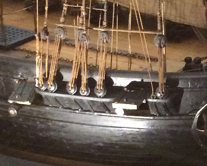
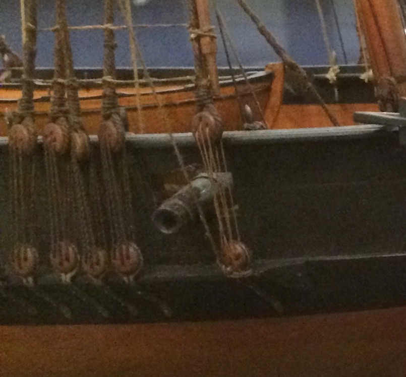
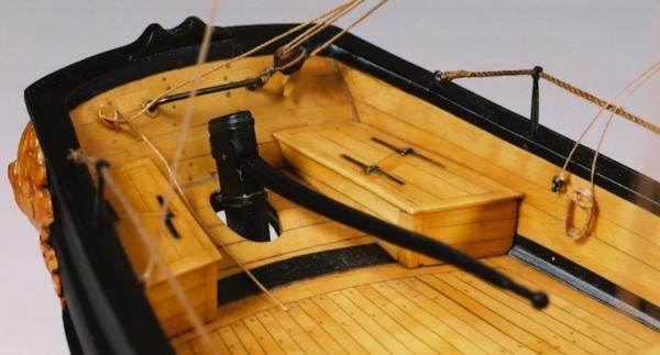
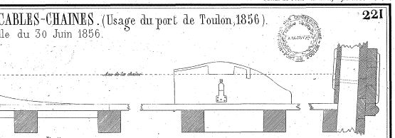
(Greetings, Tony!) Well, there must have been some tackles involved in the process of stowing the anchors on or below deck. Here an example (a fantastic model of the Topaze by Bruno Orsel, http://denis-59.forumpro.fr/t792-la-topaze-goelette-de-1823):anchors secured just in front of the tiller. Or here the open main hatch of the Mutine (from the Atlas du Génie Maritime), with an anchor stowed below (no 42 shows the holes where the anchor chains come from). Beeing a landsman, I wouldn't even speculate as to what you can and cannot do with tackles, but I always thought they were used to lift things... Gregor

- 121 replies
-
- 5
-
-
- la jacinthe
- schooner
- (and 2 more)
-
Hi aviaamator – thanks for the interesting question. I’ve wondered about that myself, but sadly I haven’t found an answer yet. None of the Jacinthe type models (contemporary or modern) I know of have something like the capstan on the schooner from the Atlas du Génie Maritime you included in your posting, or a windlass. Two contemporary models of French schooners (one from the 1st empire, the other of the following Restauration period) on exhibit in the Musée de la Marine in Paris also show nothing of the sort, as does a drawing of a schooner from 1832 in the Atlas. For now, it remains a mystery to me… But here the schooners from the Paris museum:


- 121 replies
-
- 3
-
-
- la jacinthe
- schooner
- (and 2 more)
-
Research made me to adjust my project: I will build two schooners of the Jacinthe type: La Mutine and La Topaze (http://denis-59.forumpro.fr/t792-la-topaze-goelette-de-1823). As I described before, both are based on the same basic draft which was distributed to the different dockyards (each of them to build two ships) in 1823/24. The original plan of the Jacinthe type schooner shows a mostly open bulwark. While helping the sailing qualities of the ship, this arrangement does nothing to protect men and equipment from the elements. The dockyards addressed this problem in different ways. La Mutine had a completely closed bulwark; La Topaze got a less watertight bulwark to make the construction as light as possible: The lowest of the three planks is 50% thicker than the planks above. Also the hulls of La Mutine (built in Lorient) and La Topaze (Cherbourg) show interesting differences: Only La Mutine has wales. Instead of sanding them down at the bow and stem, I cheated with the planking a bit to make the wales stand out amidships. La Topaze has no visible wales. They are not shown in the original draft of 1823, and are missing in a contemporary model of the Topaze (also the original draft of La Mutine, sent to Lorient in 1823 does not show any wales, but they appear in the plan published in 1835). The last difference to show here is the position of the gun ports. I hope to finish the hulls till the end of the year. As now both models will be painted and coppered, I made a few shortcuts while planking below the waterline. Cheers, Gregor

- 121 replies
-
- 15
-
-
- la jacinthe
- schooner
- (and 2 more)
-
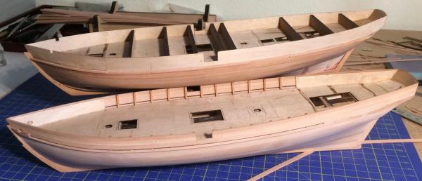
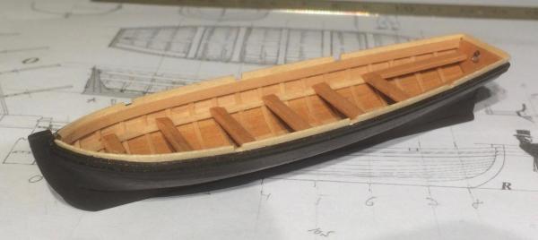
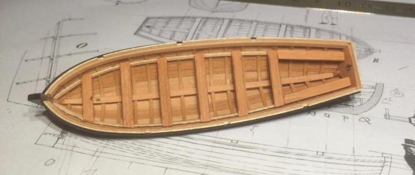
Thank you all! The juggling of hulls comes to an end: The cutter has been completed, and I will concentrate my efforts on La Mutine (I will not touch any hull smaller than 30 cm for some time!). The Irene is safely stowed away for the foreseeable future (but I will open a log for her when I return to her). Here some pics of the cutter: Cheers, Gregor
- 121 replies
-
- 11
-
-
- la jacinthe
- schooner
- (and 2 more)