HOLIDAY DONATION DRIVE - SUPPORT MSW - DO YOUR PART TO KEEP THIS GREAT FORUM GOING! (Only 36 donations so far out of 49,000 members - C'mon guys!)
×


Gregor
-
Posts
225 -
Joined
-
Last visited
Content Type
Profiles
Forums
Gallery
Events
Everything posted by Gregor
-
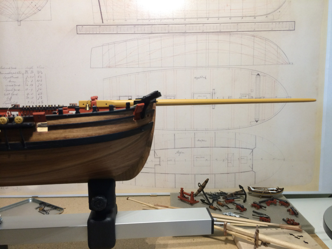
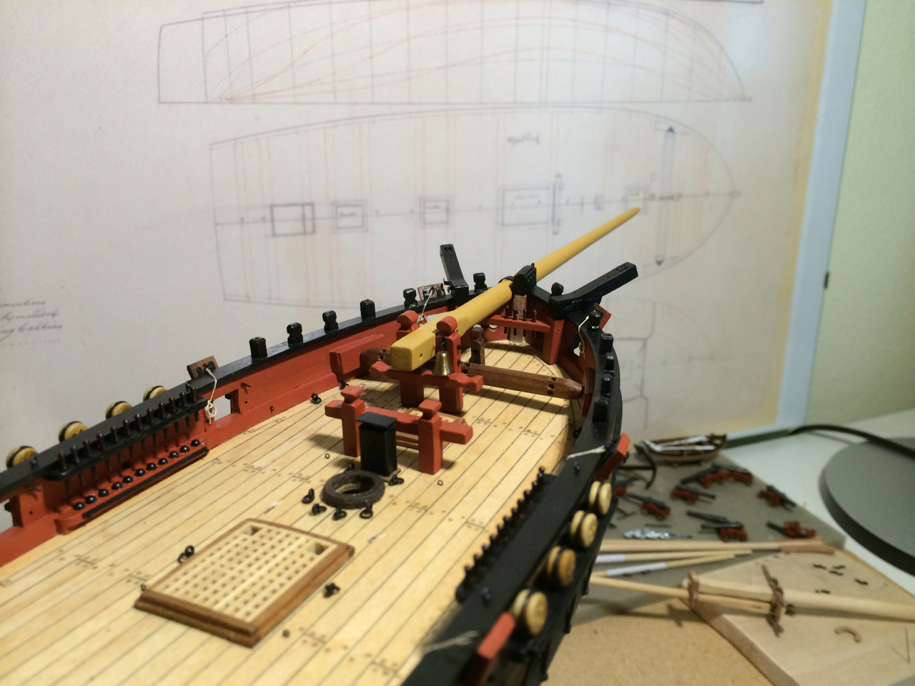
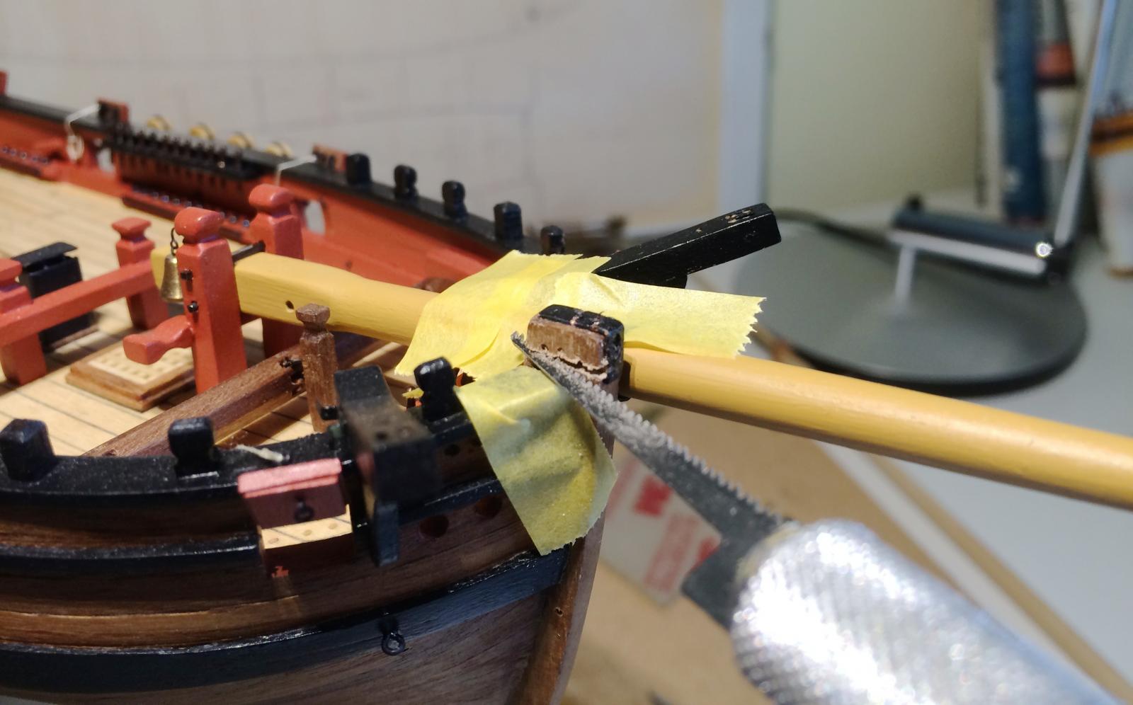
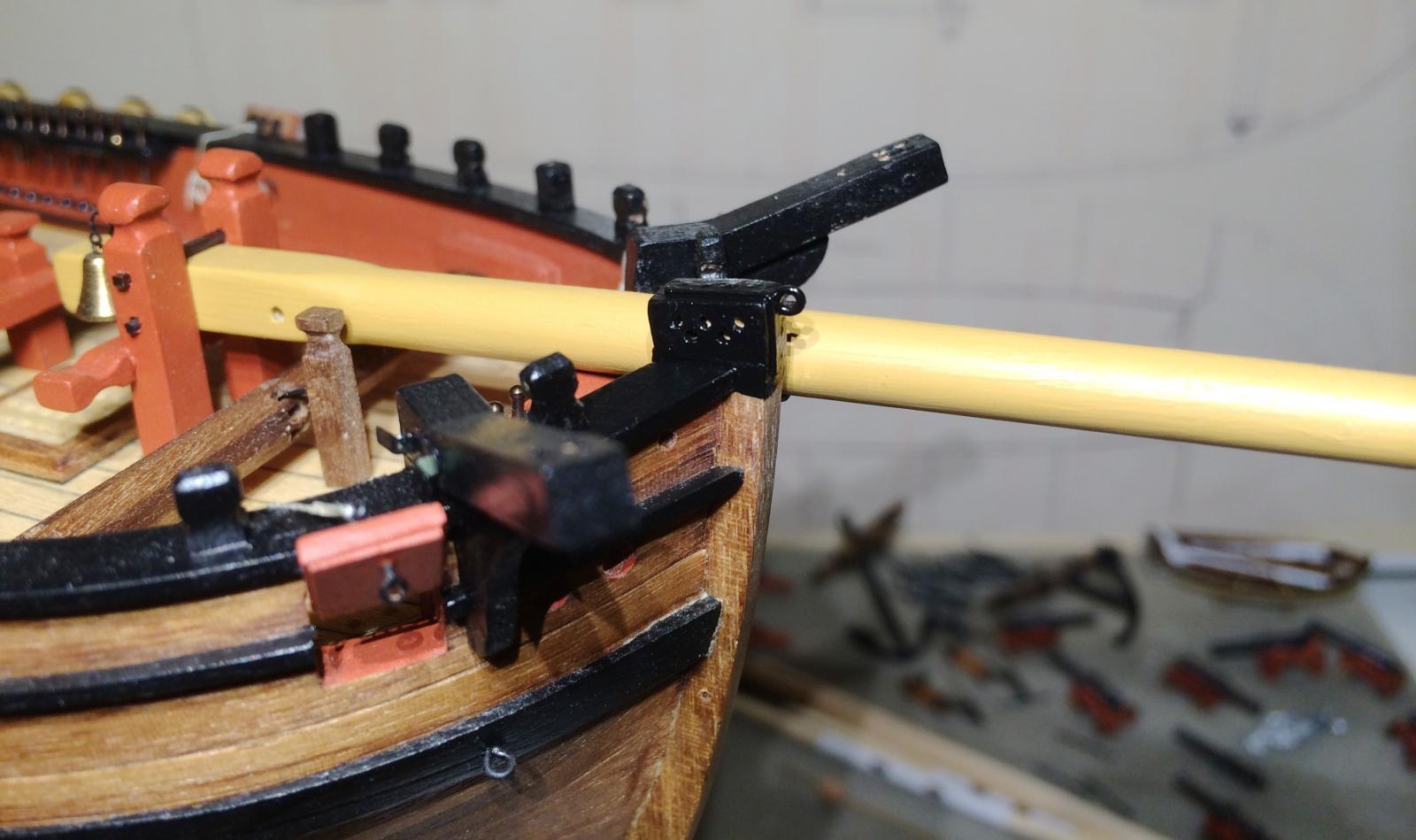
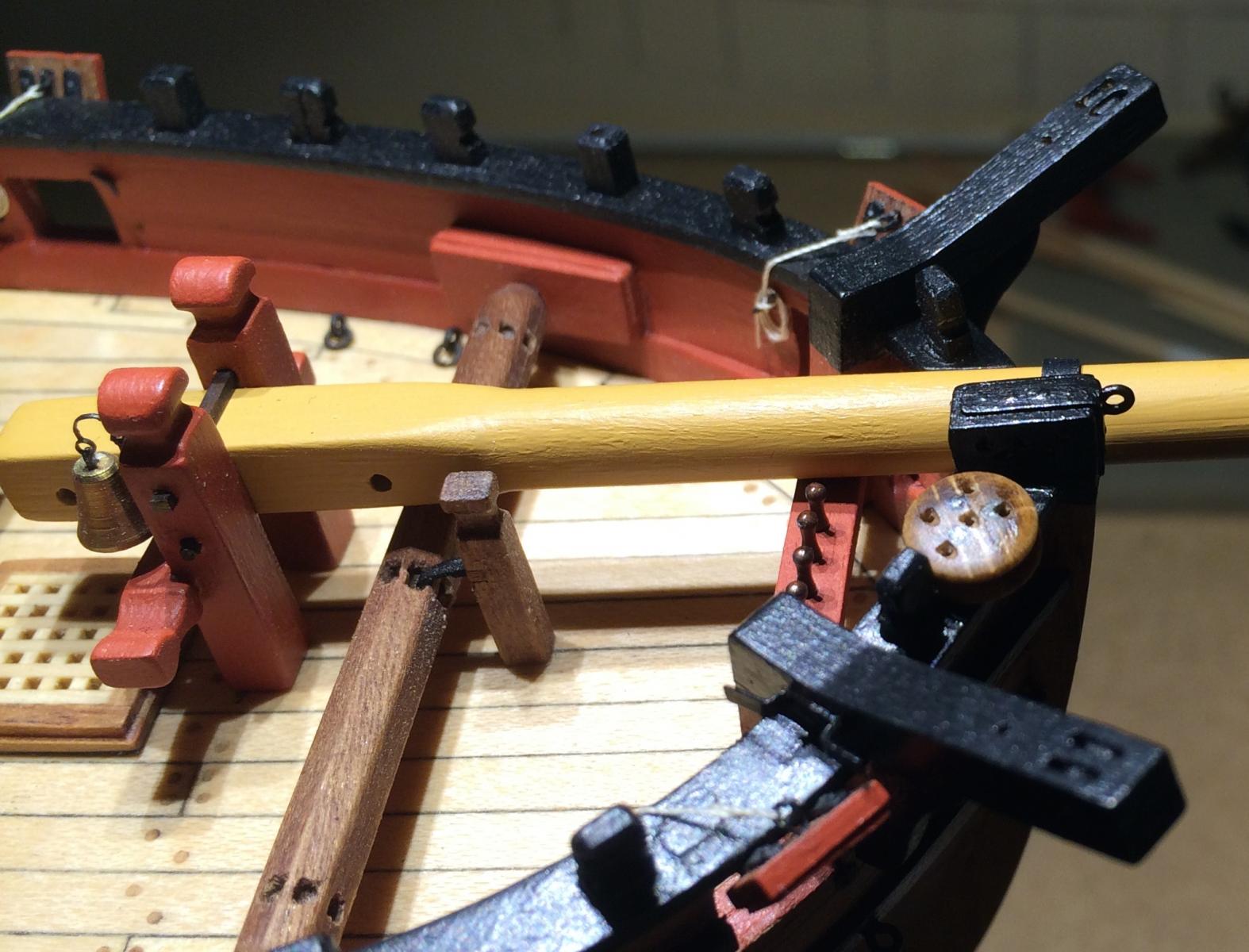
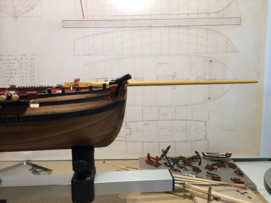
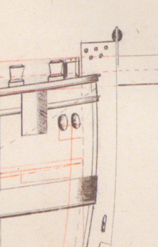
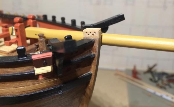
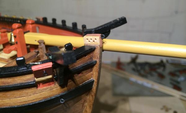
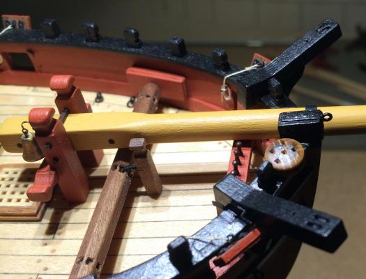
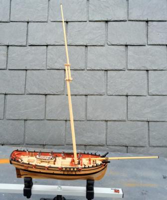
But you are correct, Dirk: On the plan there is an angle of about 6 degrees between keel and bowsprit, and that's what I made. It looks worse on this picture because of the angle distortion, and because of the tapering of the bowsprit. But here is something that (hopefully) gives you some motivation: These things were meant to be movable, after all. Thanks for this observation - I thinks it looks better now. Gregor And Tony is right. I will finish my rigging and belaying plan this weekend, if the weather does not change (it is very hobby friendly at the moment). I will be needing all the instructions and tipps I can get, and will be eternally grateful - that's a motivation, isn't it? That would be tho role of Tom Pullings, then.

- 210 replies
-
- 2
-

-
- Sherbourne
- Cutter
- (and 5 more)
-
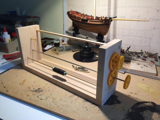
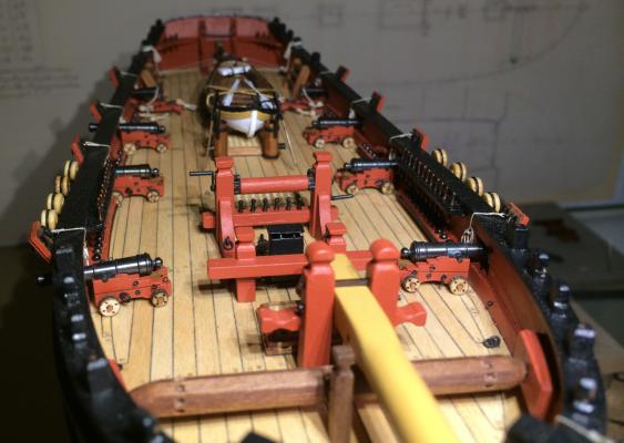
Not many words are needed in this posting: I made myself a serving machine. Thousand thanks to all the guys showing their machines here on MSW. Mostly I followed Marc (http://modelshipworld.com/index.php?/topic/4294-the-first-royal-dutch-yacht-mary-by-flying-dutchman2-mamoli-1646/?p=174488), who wrote a good tutorial, and made it with parts from the local hobby store. Since the role of Killick is already taken, I feel quite comfortable in the role of Dr M., staring at the rigging and wondering why there are trucks on top of everything and looking for horses, mice and donkeys (the cap is called donkey’s head in my native German). Cheers, Gregor
- 210 replies
-
- 3
-
-
- Sherbourne
- Cutter
- (and 5 more)
-
I used the same method with the planking as Tony, it seemed to work nicely. But try not to rely on filling the gaps later; tapering the planks is worth a special effort. If you don't mind me saying: I would suggest to check the position of gun ports two on each side regarding to the deck. If I see right on your photos they are sitting too high, so the guns will probably not fit. I had to make them a little lower, and this is best done before planking. You are making great progress, I love watching. Gregor
-
Oh, I'm looking forward to see a photo of your version in your log, Dirk! I really think it was a good idea - it would have been even better to do this right at the start. It was a bit scary, worse than taking the transom down (there were less things to destroy on deck at the time). Cheers, Gregor
-
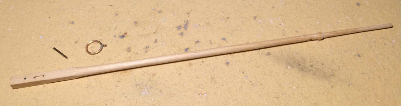
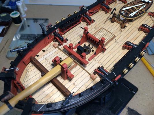
Yesterday evening I had a fit of professional conscience and had to do something very historical. As an act of contrition I laid hand on my Sherbourne and made her looking a little bit closer to the NMM plan. The following pictures speak for themselves: Then I needed a five-hole deadeye. I took the one provided with the kit, filled the three holes with superglue and sawdust, and drilled five holes today. Now I feel good and fortified for all the liberties I will take with the rigging… Cheers, Gregor


- 210 replies
-
- 4
-
-
- Sherbourne
- Cutter
- (and 5 more)
-
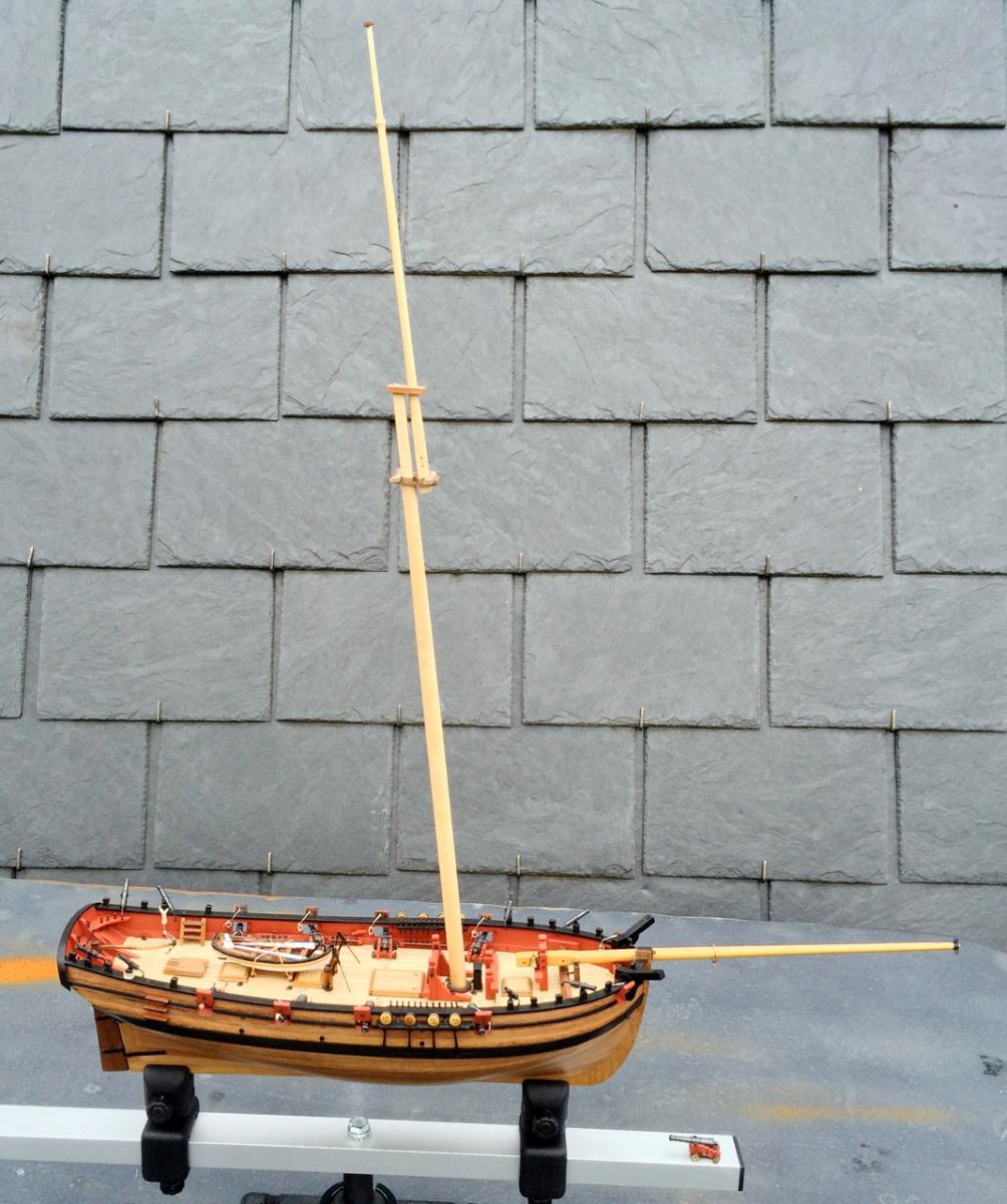
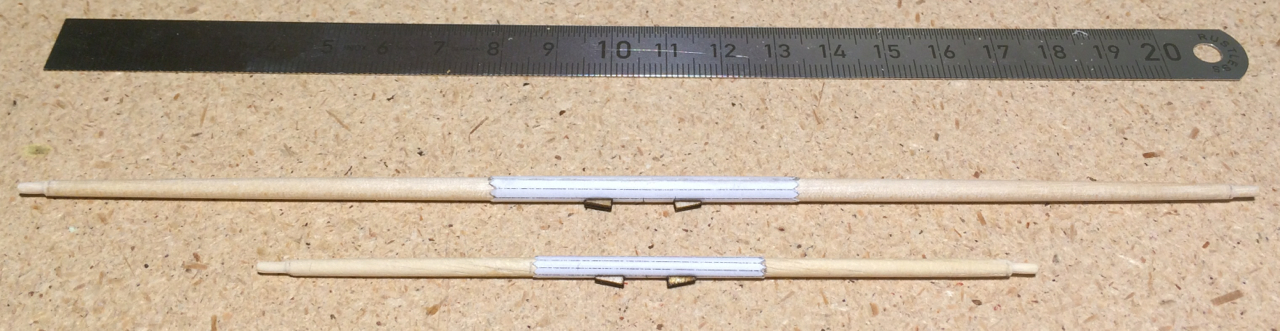
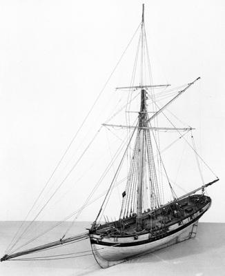
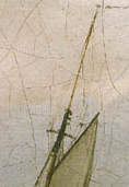
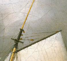
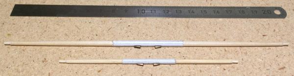
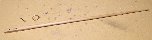
The mental fog is lifting slowly; important puzzle parts are coming together. I’ve spent a lot of time reading logs and books about rigging. Finally I could lay my hands on a copy of Petersson’s “Rigging Period Fore-and-Aft Craft”, which I had seen mentioned before. Beautiful to look at, but more importantly to me it’s like a Rigging Guide for Dummies (that’s meant as a compliment to the author). It answers in many drawings the most important beginner’s question: “What happens if I pull this string here?” I’m really glad now that I copied (almost blindly) Dirks pin arrangement, it’s almost exactly the one from Petersson’s book, and I was very happy to see that Petersson’s cutter is the same one (from the Science Museum in London) as the one in Goodwin’s Alert book, around 1785. Details of this kind of rigging can also bee seen in John’s beautiful, much younger cutter Stag. Although I know from our discussions and from the NMM plan that the historical Sherbourne had almost certainly an older version of rigging (there is a spread yard listed on the plan) like the one of the cutter Hawke from 1777, I wanted to give my Sherbourne a modernized rigging for her Second Life. It’s not historically accurate, but it’s also no anachronism. The earliest picture of this kind of rigging arrangement I could find is again the Fly from 1779. Fly’s rigging shows crosstrees and futtock staffs for the topmast shrouds, while the nameless cutter from around 1785 (the hull! the rigging might have been added later as it uses many more metal parts and hooks than older ones) only has one rigging spreader. I assume there existed a wide variety of rigging methods used in cutters at the same time. Crosstrees without futtock staffs can be seen also in the Trial, around 1790, and then many more in younger vessels. Of crosstrees there are also different shapes, mine come from Jotika’s Pickle, and are slightly rounded, which I like. But there are many drawings of straight crosstrees in cutters and other vessels. So for the first time I can see my Sherbourne as a sailing caft. Gaff and Boom are not yet ready; it’s too cold outside at the moment. But I have made mast and yards. I simply borrowed my neighbour’s electric drill from his power tool collection, sat in the sun on the roof before it went AWOL and let the spars slowly rotate through two files and/or sandpaper, always checking with plan and caliper, while I gave my fingers time to cool down. The yards are made quite simply: Following George Bandurek’s suggestion I made the battens with paper (two layers of sticky labels); the clamps are leftovers from my gun project. And finally the kit’s original guns came to glory again: I sanded down one of the original wheels and put it on the topmast. Cheers, Gregor

- 210 replies
-
- 6
-
-
- Sherbourne
- Cutter
- (and 5 more)
-
Totally derailed - I can always blame the language barrier (and should probably resume my office job now) Gregor
- 210 replies
-
- 2
-
-
- Sherbourne
- Cutter
- (and 5 more)
-
Oh, you had me there. I should probably build airplanes. Gregor
- 210 replies
-
- 2
-
-
- Sherbourne
- Cutter
- (and 5 more)
-
Well, the historical debate about gun port lids and sanitary installations is still open… If Tony is right, could horses be installations only to be mounted when in use, maybe tied between the rails? Could knight heads used for the task of temporarily belaying the staysail sheets? Or could the sheets even be belayed at the rails? I have to admit, I'm confused Gregor
- 210 replies
-
- 1
-
-
- Sherbourne
- Cutter
- (and 5 more)
-
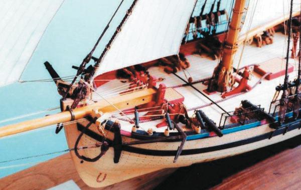
Hi Alistair, a good question. There are some contemporary drawings and paintings of cutters with gun port lids, and there is the NMM plan we had a discussion about last summer. Because they are so beautiful to look at, here the list of paintings and drawings in NMM's collection: · (1783) · (1783) · (1785) · (1788) · (1794) · (1794) · (1795) · (1796) · (1818) · (1821) · (1826) · (1830) In Goodwin's Alert book there are three pictures of an unnamed cutter from around 1785 where I took the lids and their lanyards from. They may have a practical purpose as you mention, but mostly I liked the look of the cutter Fly (1779), which shows them also (and I wanted to make something of my own, not being very good at following orders). I think Sherbourne builders are allowed a little leeway from the Alert - browsing through NMM's collection I'm under the impression this cutters were vessels very individually built. Just looking at different types of rigging during Sherbourne's real-lifetime shows a rich variety to choose from. For me that is one of the good things I discovered building this kit; it can grow into a project of your own, if you so choose. I will certainly modernize my rigging (big words for one that doesn't understand the basics yet, but like the challenge. I'm working on the mast, so I'm committed now). Ooops: With "computer labels" I meant these mostly white sticky paper things you print an address on, take the protective back off and press on an envelope (there must be a better term in English for it). I took this Idea from Blue Ensign; he called it "computer label paper" and used it for his Pickle's boats. Sorry for my linguistic assault. Gregor
- 210 replies
-
- 1
-
-
- Sherbourne
- Cutter
- (and 5 more)
-
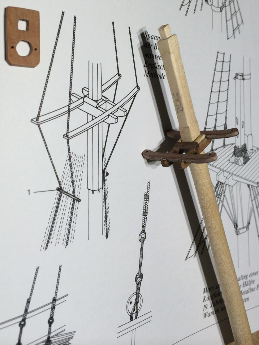
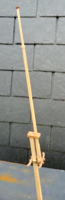
That’s a relief, Eammon – the quick model of the horse I made was way out of scale, too. Smaller wooden parts and a wire of not more than 0.5mm will make it look better. And that is really good and useful advice from the real world; anchor cables under the wire would probably result in broken shinbones, it would have been more than 30 cm over deck. I hope Kester can use this, too. You both seem to know how to sail; I’m still struggling with the basic theory. Reading and looking at diagrams is quite fun, but has its limits. Therefore I have begun to work on masts and spars. So far I have made the topgallant mast (and it’s fid, and traveller no. 3) – its symbolic, it’s far from deck and lacks a solid foundation. But these pieces will help me to understand the connection between them. This forum is really a great place; your help is much appreciated. Cheers, Gregor
- 210 replies
-
- 3
-
-
- Sherbourne
- Cutter
- (and 5 more)
-
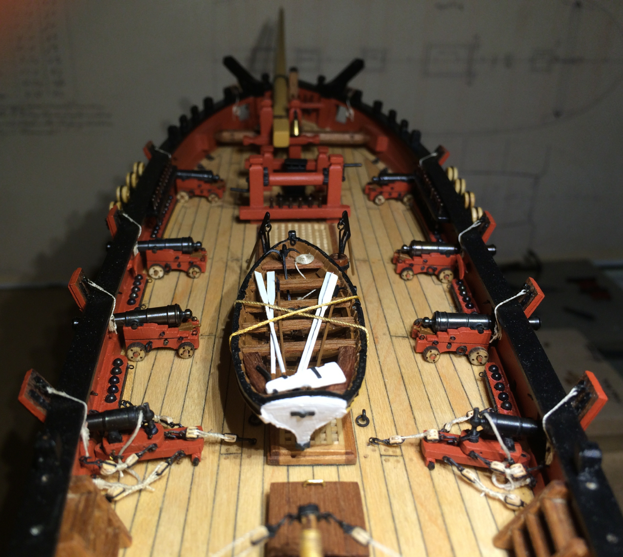
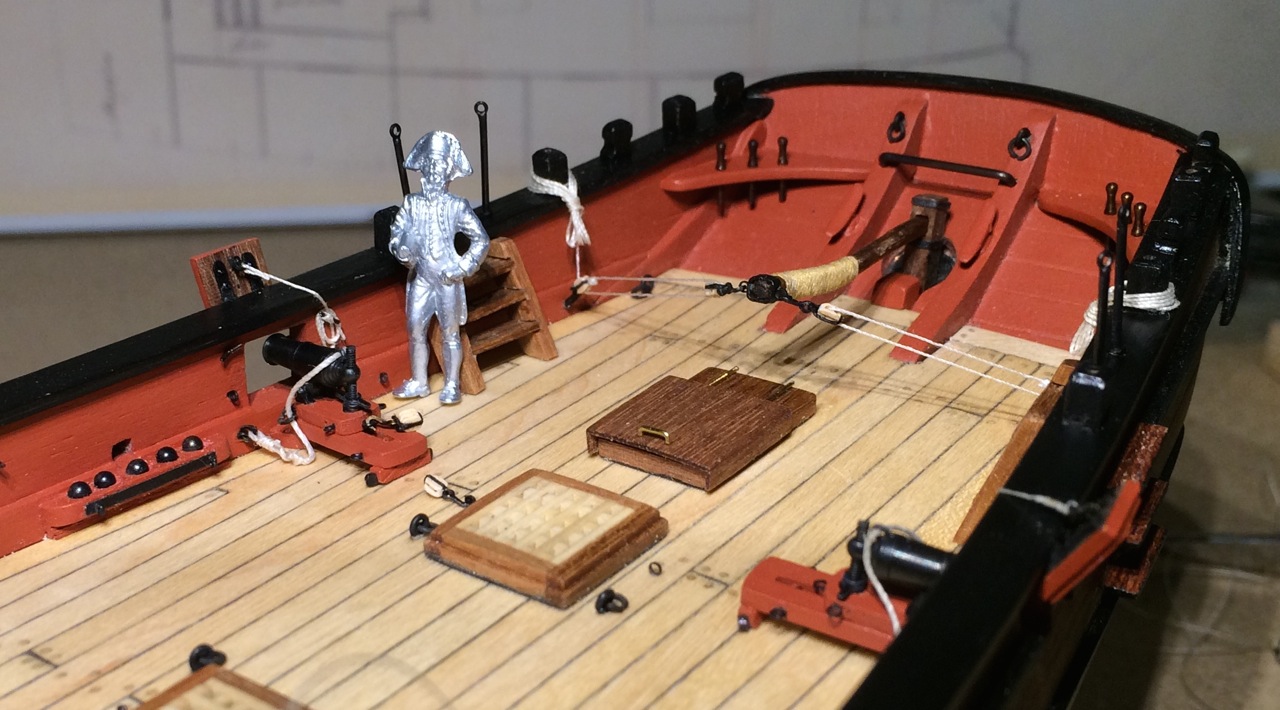
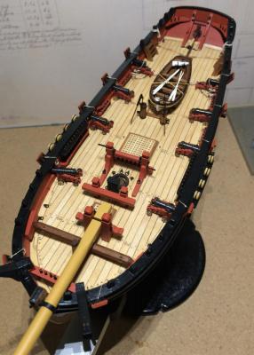
Thank you all. Alistair, I have to agree with Kester in that a boat on the starboard side does only make sense if you tow it astern before going into action (I remember reading about such preparations in Patrick O’Brian’s books). N. Robert Cole thinks that all cutters had to tow their boats (difficult to get them aboard and stow them without making working the boat impossible). But in the same paragraph he writes that the admiralty requested all vessels to hoist their boats in to reduce losses. So I guess cutters lost their boats regularly in heavy weather or had to stow them on deck to prevent that, even if this was difficult and cumbersome to do. As I have not made fast the little boat (14’, in relation to the longer Alert’s 18 footer) to the deck, I will probably show it towed in the end (there is a beautiful example in MSW’s gallery). The most important woman in my life thinks my Sherbourne’s deck too crowded anyway… It will be more crowded at the bow with the furled sails. I’m looking forward to your progress there, Kester. The Alert book shows that the jib is made fast with hooks, so it would have been easy to haul the traveller in and unhook it, leaving only the tackle hooked there and stow the sail elsewhere. The question remains open… A horse of iron, no legs (and not a underpowered car)? Thankfully Cole's model shows an example, which I copied quickly (picture taken from Cole's paper). On my Sherbourne, it would look like this, making the working of the guns beside it almost impossible. I could move back the knight heads a few millimetres and shorten the horse (what a terrible thought), but would it still work like that? I foresee pinrail crisis (part two) anyway in the nearer future. Cole’s belaying points bring Dirk’s windlass arrangement to mind, lucky him. I think they invented engines to get rid of all these problems (but lost the beauty of it on the way). Gregor

- 210 replies
-
- 2
-
-
- Sherbourne
- Cutter
- (and 5 more)
-
Welcome to the fleet! I see you’ve made a good start, keep it up. The Sherbourne is a good choice; hours of pleasure are ahead of you. As for the rigging: I wouldn’t say it’s less complicated; it’s less repetitive, having only one mast. But as I’m finding out now, almost everything is there… (Professionals, please overlook the last remark ), it adds to the fun. Enjoy building, Gregor
-
I have been thinking about sails for a long time now. The decision “no sails” or “furled sails” has not been made yet. Thinking ahead, something more basic came up: How would furled sails be made fast at the bow? The staysail can rest on the bowsprit, I think. But where does the jib go? Out on the bowsprit? Or hauled in and stowed in a bundle on deck inside the bulwark, impeding everything else (my traveller is too small anyway, I have to make a new one)? Or would it be better to take the jib off and stow in under deck? Any suggestion would be greatly appreciated. Gregor
-
I'm glad your health is getting better. I hope to see you back soon. Gregor
-
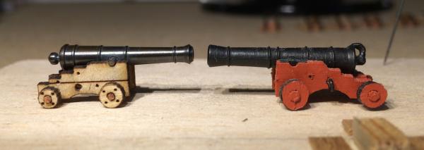
No, Tony, I don’t think the laser beats the classic method at all. It went well with this method, and it was fun being student again, but for a better result there would be a lot of designing to do. The burn marks also forced me to use paint, the wheels should be cut bigger so you can sand down the winter profile… But for the moment I’m quite pleased, the new guns fit in nicely. It was fun to use scrap parts for things like quoin handles: again I used leftover stems from 0.3 mm eyelets and a tiny drop of PVE glue. The eye bolt on the back of the rear axle will be added together with the double block later. Here a few Sunday evening pictures. As you see, I left the wheels unpainted; the plywood can still be seen. I have a cheap excuse for that: I show dowels that hold the parts of the wheels together, after all. Ok, Goodwin’s Alert shows only halves and not three parts… But the pins to prevent the wheels from falling off defeated me utterly – I can live with that. Cheers, Gregor

- 210 replies
-
- 12
-
-
- Sherbourne
- Cutter
- (and 5 more)
-
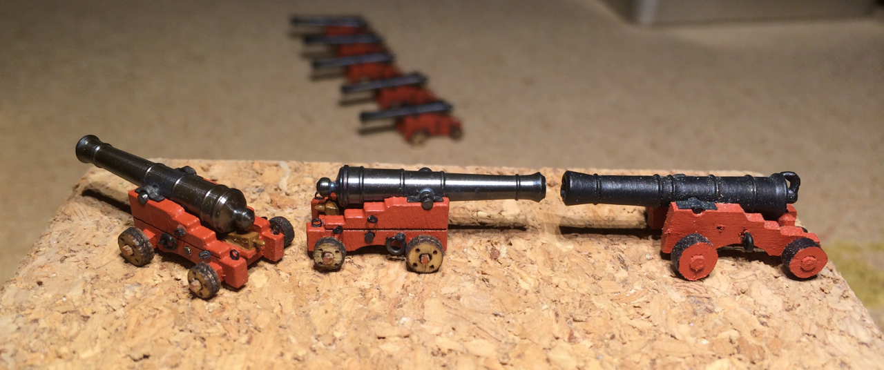
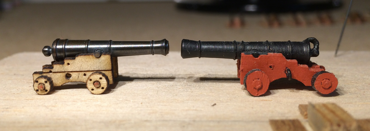
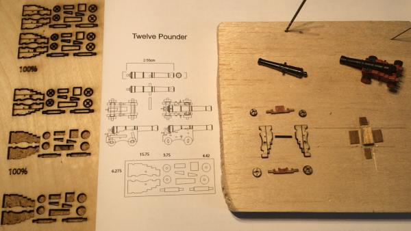
Thank you all – here some news: Finally some progress with the guns! Because I’m still resisting the temptation of buying dust-producing machines like mills and lathes – I usually do the heavy sanding outside of our apartment, peacefully on the roof – I had to look for alternative ways to make new gun carriages. A jeweller’s saw and files didn’t work successfully for me. Then I found out that our local technical university has an open lab policy: You can use their equipment like laser cutters and 3d-printers for a very tiny fee. For preparation I had to download a manual and a template file, and then show an assisting student that I know what I’m doing. Preparing the drawings with Adobe Illustrator was easy for me at home; I’m using this software often. A big help were Chuck’s drawings of a twelve-pounder gun (sadly his smallest guns are six pounders). Once there, it was like printing. That is, you have to tinker with the settings like speed, frequency and heat of the laser. Working with cheap plywood, I saw smoke and flames. But after an hour, my allotted time, I went home with more than enough carriage parts (many of the very small things were lost to the ventilating system because I forgot to draw small bridges…). At home (smells of burning wood and adhesives in my study) I had to admit that drawing is easy, but constructing is more difficult – while I tried to reengineer Chuck’s design I made some mistakes – I started with Chuck’s drawing, hence the layout, and tried to make the parts fit. But simply make something smaller doesn’t work very well; tiny differences in thickness of wood have great impact. In the end I did not use all the parts, sanding, cutting and filing was necessary to make the parts come together. If it were not for the interesting experience with the laser, I’d like to buy the kits from Chuck’s, where my blocks come from. For four-pounders I would suggest a new, simplified design. I recycled the axles from the kit’s guns. The cheeks came out well, also the wheels. In the following picture you can see the limits of this method: my wheels look like winter tyres in this magnification. More time with the laser and better wood would surely produce a better result. The best thing was, the laser could cut and scratch at the same time (red and green lines were prepared in the drawings); this gave me the markings for all the small holes to drill for the eyelets. It was even possible to cut out the holes in the wheels (1 mm). My guns are still four ponders, but I’m quite pleased with them so far. Since the guns were the first things I made when I started in summer 2012, they are proof of some progress. Cheers, Gregor
- 210 replies
-
- 6
-
-
- Sherbourne
- Cutter
- (and 5 more)
-
Hi RMC, Maybe you can improve the method I used: http://modelshipworld.com/index.php?/topic/2288-hmc-sherbourne-by-gregor-–-caldercraft-–-scale-164-1763/?p=156268 Cheers, Gregor
-
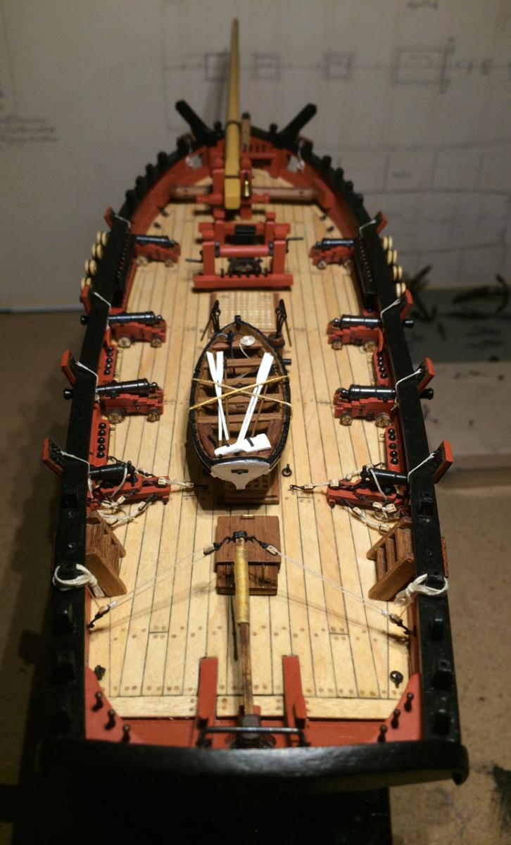
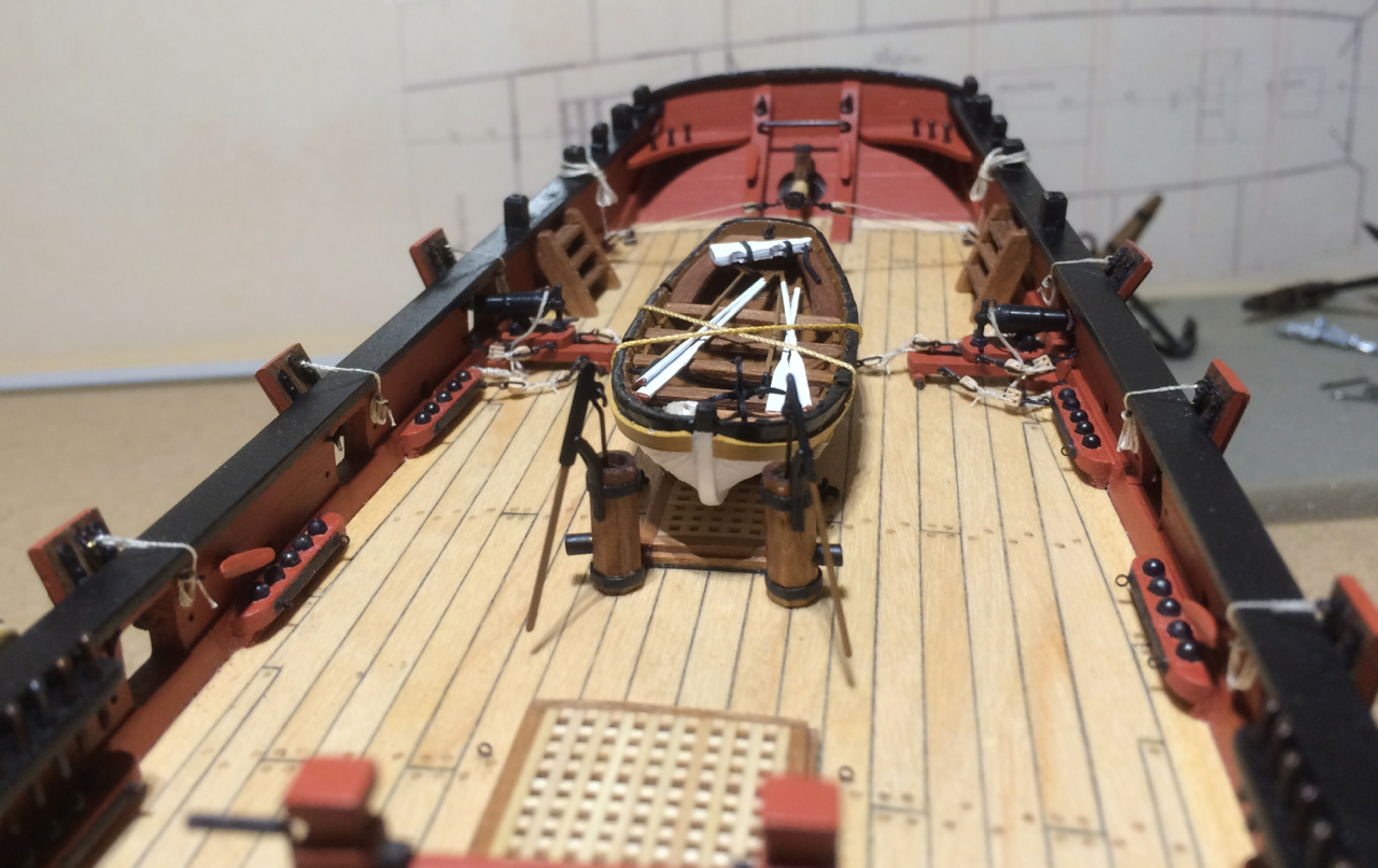
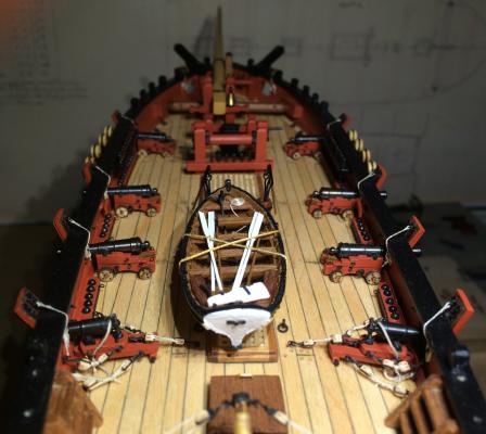
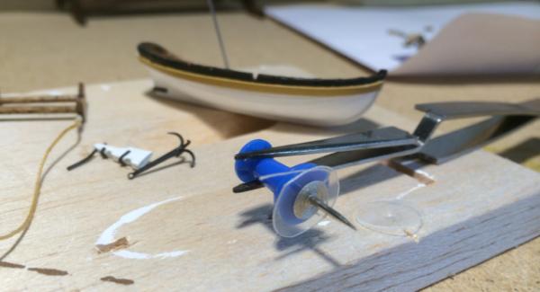
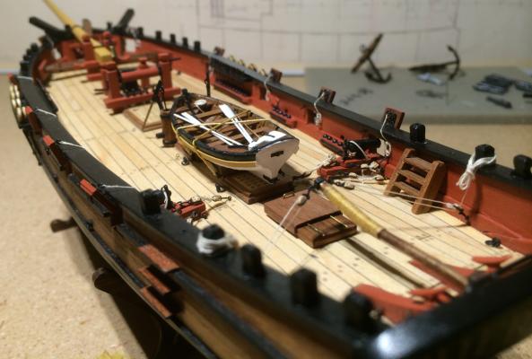
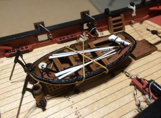
This was a rainy weekend, so I made a jolly boat, bought at the same time as the pumps. Small improvements were made (as well as mistakes). My main inspiration was Blue Ensign’s Pickle log again. Like him, I made a clinker planking out of computer label paper, cut in 3 mm strips. You can hardly see it in the pictures here, and even by eye you have to know what to look for… The best thing I learned: Instead of the splintery walnut strips provided with the kit I used the computer labels also for the ribs and raising planks on the inside and the rubbing strake on the outside – the stickiness of the labels helped a lot. For the ribs I cut strips from a double layer, the planks and strakes from four layers. They are much easier to bend, too. As I will have no rope coils around my guns, here I could make one from 0.1 mm thread. The method is shown in Modeler12’s log. The boat is not tied to the deck, as it probably should be, but only to the chocks. This way I can remove the whole thing if I decide otherwise. The smallest parts I glued on so far are the rudder pintles, made from unused stems of 0.3 mm eyelets. This was real fun. After all is done, I’m beginning to dream about making my very own jolly boat. But I will make the missing guns first. Cheers, Gregor
- 210 replies
-
- 8
-
-
- Sherbourne
- Cutter
- (and 5 more)
-
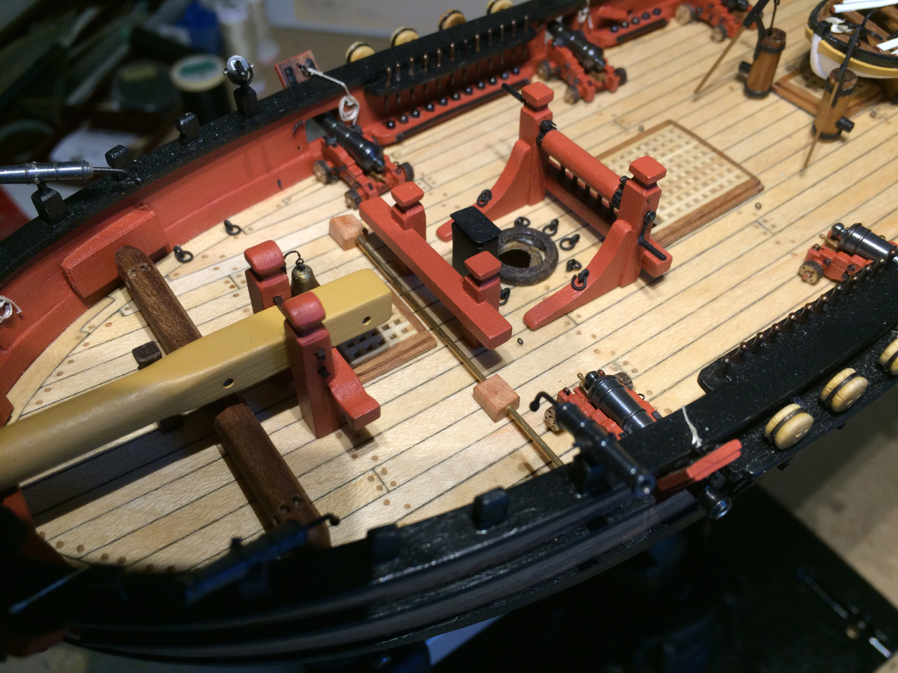
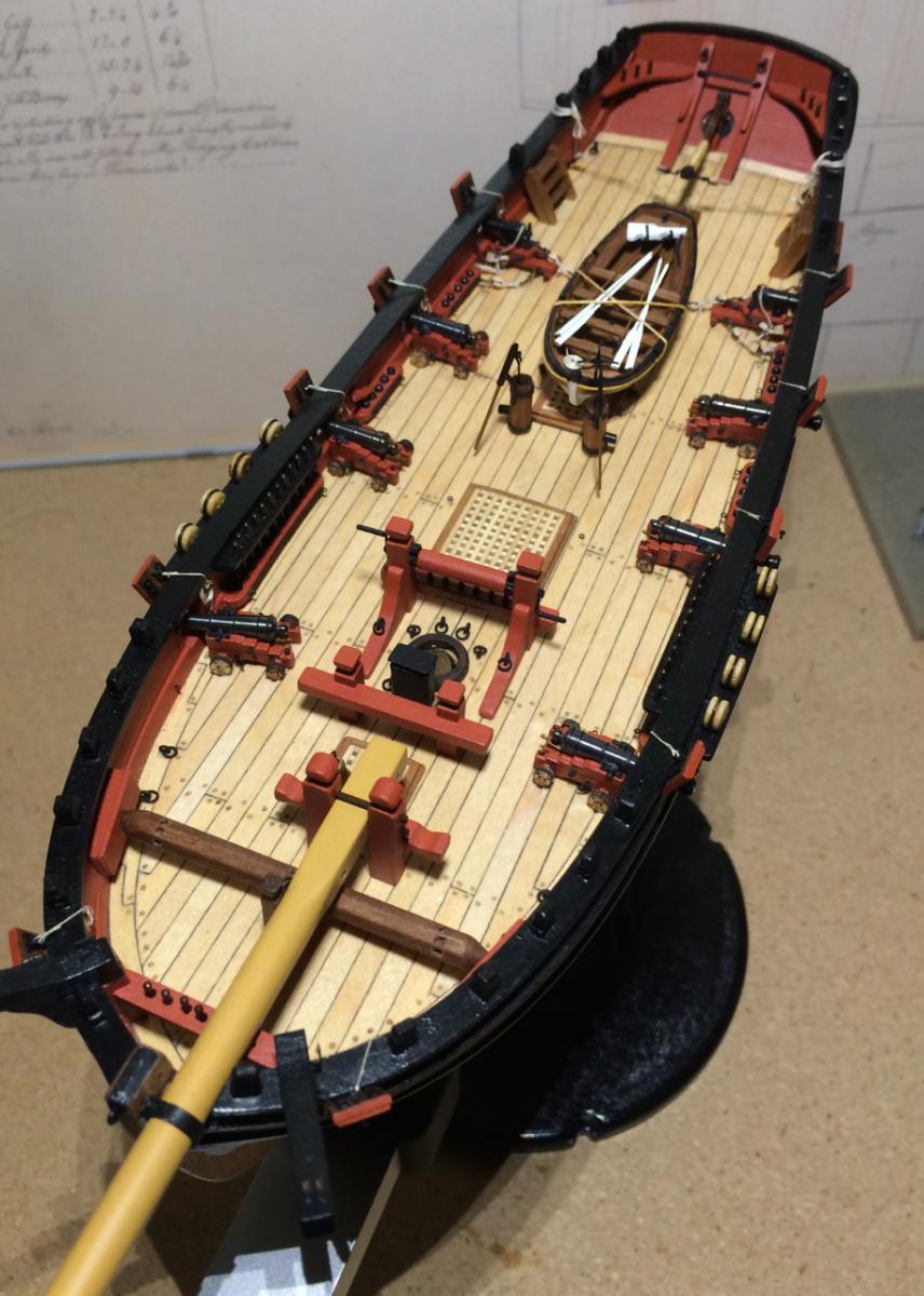
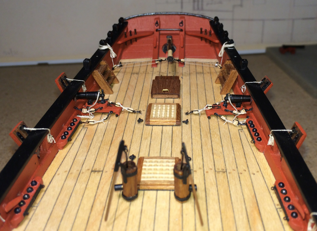
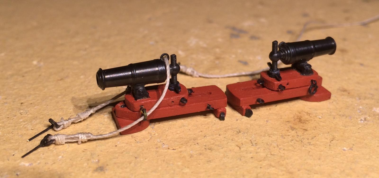
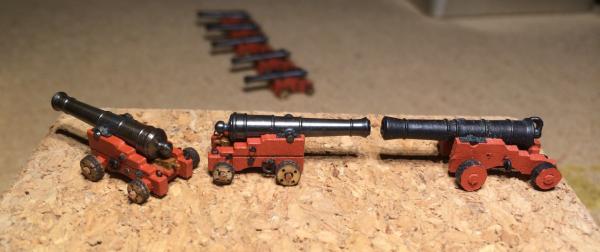
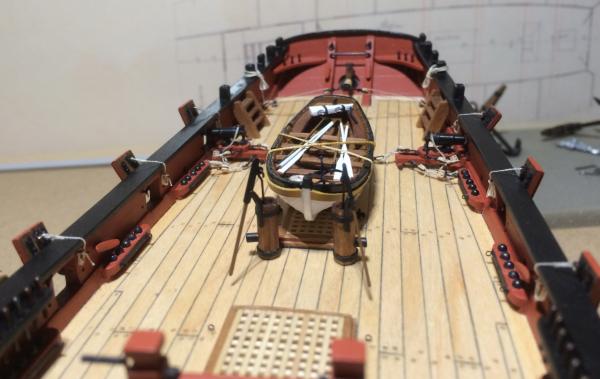
I have completed the rigging of the carronades, I’m now certified insane at home. It was kind of fun, and I’m no longer afraid of rigging the long guns when the time comes … Both carronades got a full set of five tackles, with a single and a double block (2mm from Chuck’s Syren Company) and 0.1 mm thread. They still look quite big beside these 12 pounders. I guess they weren’t used all at the same time. Here they are laid out for inspection. The rope’s ends are not cheesed down; I choose to tie them as shown in many pictures of museum replicas. The stress on the timbers we have discussed lately will have to be compensated with modernised pumps. They come from Caldercraft’s Pickle; I bought them way back when I thought I would never solder anything myself. I like the metal parts that came with the mini-kit, but took a bigger dowel to make the pump case octagonal with a file. Cheers, Gregor
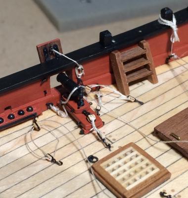

- 210 replies
-
- 7
-
-
- Sherbourne
- Cutter
- (and 5 more)
-
I’m really grateful, Tony, for your log. It shows not only the application of various techniques, but also what can be achieved with an eagerness to learn and explore, and with patience and passion. Congratulations and best wishes, Gregor
-
Jan and Kester, I think you are both totally right, technically and historically. It was a fun project, after all, which I enjoyed very much, together with this discussion. But who knows, maybe my Sherbourne is much stronger than others, breathing fresh mountain air… Gregor
- 210 replies
-
- 4
-
-
- Sherbourne
- Cutter
- (and 5 more)
-
Thanks, Kester, for the special photos of the 'situation' at the lower masthead. These will help much more than abstract plans and diagrams. I like thinking far ahead… Gregor
-
You are right, Tony, a carronade was much lighter than a long gun. According to Tucker's table a 12 pounder carronade used almost double the weight of powder to fire a ball four times the weight of a 3 pounder gun, and did this in a much more efficient way. So you get more bang for the buck. I was trained to fire heavy mortars in the final days of the Cold War, but I wouldn't dare to guess the amount of stress timbers and ropes had to handle. Comparing the construction of a gun carriage to the sled a carronade is mounted on, it seems to me that the carriage is designed to absorb heavier recoils than a carronade sled. But everything I know about firing guns on ships comes from (hugely enjoyable) novels… The cutter Lady Nelson is bigger than the Sherbourne, so I guess an upgrade to 4 pounder guns is reasonable (all the more if pleasing to the eye). But there is also the question as to how many guns there actually were. Several NMM plans give a smaller number of guns than gun ports, many of the cutters of 1763 had six guns, and eight to ten gun ports (see the Pitt as an example). There is no number of guns mentioned in the Sherbourne plans, though. Sadly I have no access to the references given in Wikipedia, which gives the number of six guns (and eight swivel guns). I guess most of our models are slightly over gunned (a male thing, obviously), and Captain Aubrey would only fire a staggered broadside to spare the timbers. My Sherbourne, in her own space-time continuum, will get her six four pounders, too, I promise. And I'm looking forward very much to Tony's new carriages! Gregor
- 210 replies
-
- 1
-
-
- Sherbourne
- Cutter
- (and 5 more)
-
Yes, these are 12-punder carronades, built for my Sherbourne. It was again the question: "What would she look like with a modernised armament?" As a historian I was trained not to dwell too much on "what if" questions. But this being my hobby, and as a big fan of alternate-history and SciFi-literature all I need is a scientific alibi, weak as it may be: The carronade was first produced in 1776 (Spencer C. Tucker 1997), soon much in demand for merchant ships, and accepted in 1779 by the admiralty. The Sherbourne at that time was too weak to have any guns at all, but her successors had a mix of carronades and long guns, therefore while carronades on an early cutter model are not historically accurate, they aren't totally anachronistic, either. The parts in Caldercraft's carronade kit are awfully small (see B.E.'s Pickle log). Besides making them a little bit lower to fit the gun ports, I added a few details, like additional 0.3mm eyebolts. The little wheels were cut from a 1.2mm brass wire; a screw (M1, the smallest I could find, a little too fat) replaced the brass wire provided with the kit; handles and a ring on the barrel were added. Now I see hours of rigging (5 tackles per carronade) ahead of me (see Dirk’s research of carronade rigging). Cheers (don't hit me too hard, please), Gregor


- 210 replies
-
- 6
-
-
- Sherbourne
- Cutter
- (and 5 more)